Article

Design of a 2DoF Ankle Exoskeleton with a Polycentric Structure and a Bi-Directional Tendon-Driven Actuator Controlled Using a PID Neural Network

Department of Mechanical Engineering, Yonsei University, Seoul 03722, Korea
*
Author to whom correspondence should be addressed.
Actuators 2021, 10(1), 9; https://doi.org/10.3390/act10010009
Submission received: 23 November 2020 / Revised: 23 December 2020 / Accepted: 29 December 2020 / Published: 4 January 2021
(This article belongs to the Special Issue Actuators on Soft Exoskeletons)

Abstract

:
Lower limb exoskeleton robots help with walking movements through mechanical force, by identifying the wearer’s walking intention. When the exoskeleton robot is lightweight and comfortable to wear, the stability of walking increases, and energy can be used efficiently. However, because it is difficult to implement the complex anatomical movements of the human body, most are designed simply. Due to this, misalignment between the human and robot movement causes the wearer to feel uncomfortable, and the stability of walking is reduced. In this paper, we developed a two degrees of freedom (2DoF) ankle exoskeleton robot with a subtalar joint and a talocrural joint, applying a four-bar linkage to realize the anatomical movement of a simple 1DoF structure mainly used for ankles. However, bidirectional tendon-driven actuators (BTDAs) do not consider the difference in a length change of both cables due to dorsiflexion (DF) and plantar flexion (PF) during walking, causing misalignment. To solve this problem, a BTDA was developed by considering the length change of both cables. Cable-driven actuators and exoskeleton robot systems create uncertainty. Accordingly, adaptive control was performed with a proportional-integral-differential neural network (PIDNN) controller to minimize system uncertainty.

1. Introduction

An exoskeleton can help the wearer to maintain posture or perform agile movements, by performing the role of assisting or supporting the forces by understanding the intention of the wearer for the desired movements. Additionally, it can play a role in preventing external shocks that may occur, in advance. Wearable systems are being researched in various fields according to the purpose of each field, including the military, industrial, rehabilitation, and medical care fields [1,2,3]. The number of musculoskeletal patients with gait disorders is currently increasing, because the elderly population is increasing. Therefore, many robots to help patients, including wearable robots to help with daily life and rehabilitation robots to recover muscle strength, have been developed [4,5,6]. These robots support daily life by assisting the wearer’s muscle strength and performing rehabilitation training. Research has already shown that walking ability can be improved by wearing an exoskeleton robot for gait rehabilitation [7].
The anatomical axis of the ankle joint is two degrees of freedom (2DoF), consisting of the talocrural joint and the subtalar joint [8]. When walking, the talocrural joint contributes to dorsiflexion, preventing the foot from dragging on the ground and providing a balanced gait pattern through proper rotation of the foot, and plantar flexion, which provides propulsion to move forward. Therefore, the ankle balances the body when walking through the complex rotation of the two joints [9]. However, if the ankle is not functioning properly, such as in patients post-stroke or with hemiplegia, the reduced plantar flexion function during push-off inhibits the contribution to anterior propulsion. Moreover, the reduced dorsiflexion function during the swing increases the risk of falling, due to a narrower foot gap. This decrease in function causes a circumduction gait phenomenon during walking, due to the drop-foot phenomenon [10]. Therefore, due to the circumduction gait, the hip flexural muscle is under excessive burden from the imbalance in walking, which can lead to lower back pain [11,12]. As mentioned above, the ankle rehabilitation technology for solving the ankle function problem can be classified into an exoskeleton robot and a platform-based device. Platform-based devices are mainly developed for the treatment of ankle musculoskeletal and nerve injuries, and exoskeleton robots are more focused on ankle-related gait training [13]. In addition, ankle exoskeleton robots are applied to reduce metabolic cost and electromyography (EMG) by assisting the movement of the ankle [14,15]. The actuator of the ankle exoskeleton is selected for the purpose. In general, series elastic actuator (SEA) is selected when more stability of the system is required [16,17], and artificial muscles and Bowden cables are used to reduce the weight of the system [18,19,20], and electric motors are used when strong torque is required [21]. However, most of the developed lower-limb exoskeleton robots are 1DoF systems that consider only the sagittal plane, which does not coincide with the axis of the ankle. Some are 2DoF systems that consider the sagittal and coronal planes, but without these coinciding with the actual ankle axis [22,23]. Such a system causes misalignment between the robots and humans, and limits the range of motion, causing the wearer to feel uncomfortable and reducing walking stability. In the case of the hip joint and knee exoskeleton robots, studies are being conducted based on anatomical data to minimize misalignment between robots and humans [24,25,26]. However, in the case of the ankle, little research has been conducted. Therefore, this research institute developed a 2DoF ankle exoskeleton robot that matches the anatomical axis of the ankle joint, by establishing a coordinate system based on anatomical data and calculating the spatial formula of the talocrural joint and subtalar joint. This 2DoF ankle exoskeleton robot is capable of dorsiflexion, plantar flexion, inversion, and eversion [27]. In addition, the ankle joint does not rotate in one center while walking; the axis position changes. For example, as shown in Figure 1a, the talocrural joint descends below the existing axis in dorsiflexion and rises upward in plantar flexion [28,29]. For this reason, during dorsiflexion, the orthosis axis is above the ankle axis, the pressure is applied to the anterior side of the leg, and the orthosis moves in the posterior and distal directions [30,31]. Therefore, if the joint change is not considered, the wearer feels uncomfortable due to misalignment, and the balance is broken when walking, reducing stability. Dorsiflexion and plantar flexion of the talocrural joint is similar in motion to the four-bar linkage system, and comfortable walking is possible by following the change in the position of the talocrural joint during dorsiflexion and plantar flexion. As shown in Figure 1b, it can follow the movement of the instantaneous center of rotation (ICR) that moves during dorsiflexion and plantar flexion, thereby increasing stability by reducing misalignment between the human and robot during walking. Accordingly, the developed 2DoF ankle exoskeleton robot was applied with a four-bar linkage system. The structure was designed similarly to the Chebyshev linkage, a type of four-bar linkage.
Unlike other joints in the body, due to its location in the foot, the ankle joint is incredibly weight-bearing; if the actuator is placed near the ankle joint, a much greater load is felt relative to a device situated near the center of the body. Additionally, simply wearing a robot increases the wearer’s metabolic expenditure [32]. Therefore, unlike other joints, a relatively light actuator must be installed, and it is effective to position the actuator in the center of the body to reduce the sensory weight of the actuator. A tendon-driven actuator that can support the ankle movement in the center of the body is currently being developed. Most tendon-driven actuators have been developed as bi-directional tendon-driven actuators that can assist with dorsiflexion and plantar flexion of the ankle with a single motor. However, most bi-directional tendon-driven actuators are designed without considering the difference in length changes of both cables during the gait cycle. This causes unstable movement, resulting in misalignment between the human and robot. For this reason, a tendon-driven actuator that controls dorsiflexion and plantar flexion with two motors has been developed, but in this case, the cost and weight of the actuator are increased. Therefore, by measuring the rotational change of the talocrural joint and subtalar joint during walking, and calculating the length change of both cables according to dorsiflexion and plantar flexion, we developed a bi-directional tendon-driven actuator (BTDA) that can account for differences in the length changes of both cables.
If perturbation occurs in the system parameters, a proportional-integral-differential (PID) controller can only function properly if these changes are small. Therefore, in the case of a linear time-invariant process, a conventional PID controller is suitable, but a system with high nonlinearity needs to change its parameters over time [33]. However, most systems are nonlinear; therefore, it may be difficult to minimize the uncertainty of the existing PID controllers. Likewise, the ankle joint of the developed exoskeleton robot is composed of a four-bar linkage, and the movement of the subtalar joint cannot be completely controlled by controlling the structure of the 2DoF with the talocrural joint and subtalar joint, based on data of the talocrural joint. Thus, mechanical uncertainty arises. In addition, unlike general fixed actuators, the cable is relatively flexible, which causes more mechanical uncertainty. As described above, the uncertainty has multiple causes, and the exact force cannot be delivered to the wearer. Therefore, this study minimizes the uncertainty and achieves better control by applying the PID neural network controller (PIDNN), which enables adaptive control by updating the weight of the gain value of the existing PID controller through an artificial neural network [34,35,36]. The weights are updated through back-propagation.
The rest of this paper is organized as follows: The configuration of the 2DoF ankle exoskeleton robot and a method of estimating the actual ankle angle with a sensor on the ankle joint applied by the four-bar linkage is described in Section 2 [37]. The method of calculating the length change of both cables and the designed BTDA based on the calculated range of motion of the cable is described in Section 3 [38]. The structure of the PID neural network controller and the mathematical theory of back-propagation training are described in Section 4. System verification through the experimental environment setup and experimental results is covered in Section 5, and the results are discussed in Section 6. Finally, the research conclusions are covered in the last section.

2. Mechanical Design of the Polycentric Ankle Joint

A 2DoF ankle exoskeleton robot developed by this research institute was constructed based on Isman’s actual human anatomy measurement data [8,17]. The position of the talocrural joint is at an average of 8 mm in the anterior direction and 3 mm in the distal direction of the distal tip of the fibular malleolus. The calculated talocrural joint and subtalar joint were designed based on Equations (1) and (2). An arbitrary coordinate system was set as the origin at the intersection of the ankle joint and the plane, perpendicular to the ground and including the middle of the foot.
y = z 0.1763
x 1 = y 0.4245 = z + 7.04 2.2452
The x-axis is the line perpendicular to the plane containing the talocrural joint, and the y-axis is the line passing through the origin and perpendicular to the x-axis. The z-axis is a line that passes through the origin and is perpendicular to the ground.
As shown in Figure 2a, the length of l 4 was selected by summing the position change D about the average z-axis of the talocrural joint along with the DF of the ankle and the position change P according to the PF. Therefore, the polycentric structure was designed to match the position change of the talocrural joint and the ICR of the for-bar linkage. Foot length is mostly affected by the length of the metatarsal bones rather than the length of the heel. Therefore, as shown in part C of Figure 2b, the structure was designed around the heel, not the entire sole. l 1 and l 2 are the crank parts of the four-bar linkage, l 3 is the coupler, and l 4 is the ground part. Table 1 shows the length of the link in the polycentric structure.
The ankle has a range of motion of about 50° for dorsiflexion and about 30° for plantar flexion. The range of motion of the ankle depends on the walking speed. When the walking speed is 2 km/h, the average dorsiflexion is about 10° and the plantar flexion is about 20° [39,40]. Accordingly, the developed 2DoF ankle exoskeleton robot was designed to meet the maximum range of motion. The 2DoF ankle structure was designed as shown in Figure 2b. As shown in Figure 2a, the structure of the talocrural joint is composed of a four-bar linkage, which is a polycentric structure.
During dorsiflexion and plantar flexion of the ankle, the polycentric structure moves as shown in Figure 3a. The designed 2DoF ankle exoskeleton robot obtained joint rotation data while walking, through encoders attached to the talocrural joint and subtalar joint. The data in Figure 3b are the rotation data of the ankle joint obtained while walking while wearing an actual exoskeleton robot. Rotation data were obtained when the walking speed was 1km/h, and the range of motion was about 4° for dorsiflexion and about 13° for plantar flexion.
To perform gait training, it is necessary to understand the gait cycle and gait stage. The gait pattern is possible by measuring the torque of the ankle, but most of the patients who need gait training have difficulty in estimating the gait pattern using only the ankle torque because their ankle does not function properly. Therefore, it is possible to accurately estimate the gait pattern; ankle patients can estimate the angle of the ankle only by the movement of the leg by analyzing the correlation between the ankle angle of two degrees of freedom with an inertial measurement unit (IMU) sensor attached to the thigh and shin. Therefore, it is necessary to measure the actual angle of the ankle to analyze the correlation with the IMU sensor. However, as shown in Figure 2a, it is difficult to directly estimate the actual ankle angle due to the complex structure of the ankle joint. Therefore, the encoder was connected to one axis of the polycentric structure and converted to the actual ankle angle. Through this process, the relative angle of the tibia and talus was estimated in the actual human body. This can be calculated by Equations (3) and (4), by analyzing the position of the link using the algebraic method.
θ 5 = 2 atan B + B 2 4 AC · sgn θ 2 2 A
where
K 1 = l 4 l 1   K 2 = l 4 l 3
K 3 = l 1 2 l 2 2 + l 3 2 + l 4 2 2 l 1 l 3
A = cos   θ 2   K 1 K 2 cos   θ 2 + K 3
B = 2 sin   θ 2
C = K 1 K 2 + 1 cos   θ 2 + K 3
sgn   θ 2 = + 1 1 :   :   0 θ 2 < 180 180 θ 2 360
Finally, the relative angle between the tibia and talus can be determined through Equation (4), using θ 3 and θ 2 measured by the encoder. The calculated relative ankle angle was used to estimate the actual ankle angle and control the ankle position.
θ T = α +   θ 2 + θ 5

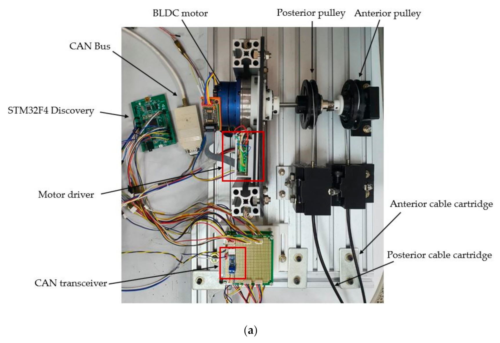
3. Design of the Bi-Directional Tendon-Driven Actuator (BTDA)

The change in the length of the cable can be calculated through the position of the insertion of the cable due to the rotation of the talocrural joint and the subtalar joint during the gait cycle. One end of the cartridge of the cable is connected to the origin (Figure 4), and the range of motion of the cable is from the origin to insertion. The talocrural joint structure is more complex than the subtalar joint structure, therefore the y-axis of the coordinate system was established parallel to the talocrural axis.
Firstly, the insertion of the anterior and posterior cables according to rotation in the talocrural joint and the change in the position of the subtalar axis were calculated using the forward kinematics formula of the 3DoF manipulator.
X n = l 1 cos θ 5 + l 2 cos θ 5 + θ 6 + D n cos θ 5 + θ 6 + B 1 n
Z n = l 1 sin θ 5 + l 2 sin θ 5 + θ 6 + D n sin θ 5 + θ 6 + B 1 n
Here,
B = θ 7 θ 8 θ 9 θ 10
where n is 1~4. X n of Equation (5) is the changed position in S n x on the x-axis in the spatial coordinate system. X 1 and X 2 are points on the subtalar axis. X 3 is the insertion position on the x-axis of the anterior cable, and X 4 is the insertion position on the x-axis of the posterior cable. Z n of Equation (6) is the S n z position on the z-axis. D n is the linear distance from P to point S n . B is a four-by-one matrix that represents the angle between points S n and P. The y-axis of the coordinate system coincides with the talocrural axis, therefore each point on the y-axis according to the rotation is the same as the initial position. Therefore, the formula of the subtalar joint, according to the rotation of the talocrural axis and the insertion position of both cables on the coordinate system, can be calculated by Equations (7)–(9).
S subtalar   =   X 2 X 1   S 2 y S 1 y   Z 2 Z 1
S 3 = X 3   S 3 y   Z 3
S 4 = X 4   S 4 y   Z 4
Equation (7) is the formula of the subtalar joint according to the rotation of the talocrural joint. Equation (8) is the position of the anterior cable according to the rotation of the talocrural axis, and Equation (9) is the position of the posterior cable. Secondly, the change in the position of the insertion of both cables according to the rotation of the subtalar axis can be obtained by using Equation (10), RRM (Rodrigues’ rotation matrix) [41]:
R subtalar = I + sin θ sub K subtalar + 1 cos θ sub K subtalar 2
where
K subtalar = 0 S subtalar z S subtalar y S subtalar z 0 S subtalar x S subtalar y S subtalar x 0
where S subtalar is the normalized vector of the subtalar joint, θ sub is the rotation angle of the subtalar joint, I is a three-by-three unit matrix. Therefore, the length change of the anterior and posterior cables due to the complex rotation of the talocrural joint and the subtalar joint during walking is the same as in Equations (11) and (12).
Anterior   cable   length = R subtalar · S 3
Posterior   cable   length = R subtalar · S 4
As can be seen in Figure 5, the difference between the anterior and posterior cables was calculated to be about 20 mm at maximum. Overall, the length change of the posterior cable is larger than that of the anterior cable. Therefore, the pulley connected to the anterior cable was designed to correspond to the length of the posterior cable. As shown in Figure 6, the BTDA was designed to control the anterior and posterior directions by connecting two pulleys to the shaft on the motor. The anterior cable assists dorsiflexion, and the posterior cable assists plantar flexion.
The pulley connected to the posterior cable in Figure 6a needs a strong torque, because it assists the plantar flexion which provides propulsion when walking. In general, at a walking speed of 2.6 m/s, dorsiflexion generates a torque of 0.3 Nm/kg, and plantar flexion generates a torque of 1.3 Nm/kg [42]. Therefore, to improve the stability by improving the impedance of the system, a series elastic system with higher spring stiffness than the anterior pulley was applied [43]. Therefore, the posterior pulley has three springs with high rigidity, and the anterior pulley has two springs in consideration of the length change of the cable and the size of the pulley. Figure 6b shows a pulley connected to an anterior cable, with a compression spring inserted to solve the relatively long length change in the posterior cable. Therefore, when the anterior cable is rotated in the unwinding direction, the spring is compressed to overcome the difference in length of both cables.

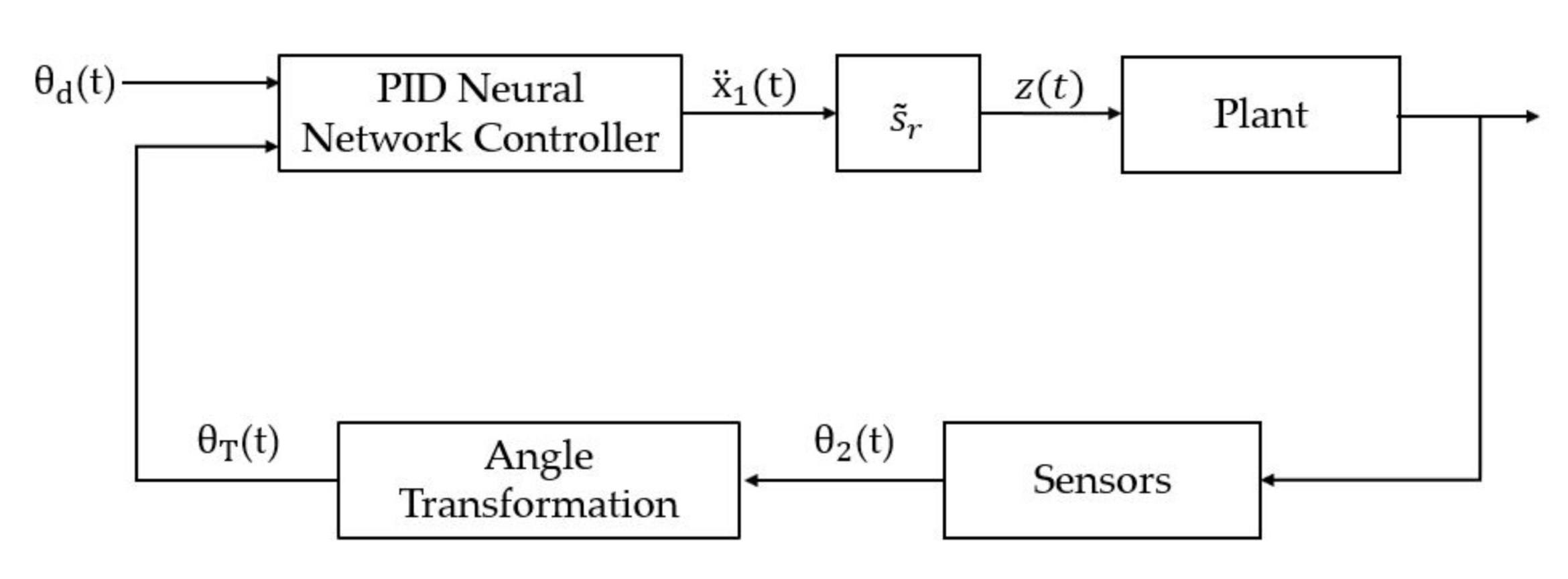
4. Design of the PID Neural Network Controller

To minimize the uncertainty of the exoskeleton robot system, a PID neural network controller was applied. As shown in Figure 7, the PID neural network controller is a controller to which the PID algorithm of an artificial neural network is applied; it consists of three layers. The input layer consists of reference values and system output values. The hidden layer consists of neurons containing PID gains. The output layer computes the signals which the controllers provide to the system. Unlike the PID controller, the PID neural network controller can update weights through back-propagation. In other words, adaptive control is possible because the PID gain is updated.
The input–output functions in the input layer are normalized values, and the output value of the input neuron can be expressed as Equation (13):
x i t =   1 o i t 1 o i t > 1 1 o i t 1 o i t < 1
where i is 1,2, and t is the amount of data. The hidden layer creates neurons that perform the PID algorithm by multiplying the neurons of the input layer and weights. Neurons in the hidden layer can be represented by Equation (14):
o · j t =   j = 1 3 i = 1 2 w ij x i t
where j is 1,2,3, and w ij is the weight between the input layer and the hidden layer. The initial weight of w 1 j   is +1, and w 2 j   is −1. Therefore, o · j t becomes the angular error difference between the reference value and the output value. Thereafter, the angular error values can be obtained by using Equations (15)–(17) to obtain the PID neuron located in the hidden layer.
x · 1 t =   1 o · 1 t 1 o · 1 t > 1 1 o · 1 t 1 o · 1 t < 1
Equation (15) is an equation for obtaining the output value of the P-neuron, and similarly, the output value of the I-neuron and the output value of the D-neuron can be obtained by Equations (16) and (17), respectively.
x · 2 t =   1 x · 2 t 1 + o · 2 t 1 o · 2 t > 1 1 o · 2 t 1 o · 2 t < 1
Here, the output value of the I-neuron can be obtained by adding the input value of the I-neuron from the output value of the previous I-neuron. The output value of the D-neuron can be obtained by subtracting the input value of the previous D-neuron from the input value of the current D-neuron. Next, as shown in Equation (18), the neuron of the output layer can be obtained by multiplying the output value of the hidden layer and the weight of the hidden layer. Therefore, the output value of the output layer can be obtained through Equation (19).
o ¨ 1 t =   i = 1 3 w 3 i x · i t
x ¨ 1 t =   1 o ¨ 1 t 1 o ¨ 1 t > 1 1 o ¨ 1 t 1 o ¨ 1 t < 1
where x ¨ 1 t is the speed of the motor that enters the system, and the input value z t is multiplied by the output value x ¨ 1 t of the output layer and the scale factor s ˜ r to adjust the scale.
After that, the weight was updated using the back-propagation training algorithm according to the error value propagated through the system. The squared error method was used as the error function.
w ij t + 1 =   w ij t   η J w ij
Here,
J =   t = 1 N E t   =   1 N t = 1 N r t y t 2
where r t is the reference value, y t is the system output values, and N is the number of samples. η is the learning rate and serves to adjust the update rate to prevent overshooting of the error slope. The error function for updating the weight of the hidden layer can be expressed as Equation (21) for convenience of calculation.
J w 3 j   2 N t = 1 N r t y t y t y t 1 x ¨ 1 t x ¨ 1 t 1 x · j t
Therefore,
w 3 j t + 1 =   w 3 j t +   η 2 N t = 1 N r t y t y t y t 1 x ¨ 1 t x ¨ 1 t 1 x · j t .
In addition, the weight update in the input layer can also be expressed as Equation (23).
J w ij   t = 1 N r t y t x · ij t x · ij t 1 o · ij t o · ij t 1 w 3 j x i t
Therefore,
w ij t + 1 =   w ij t +   η t = 1 N r t y t x · ij t x · ij t 1 o · ij t o · ij t 1 w 3 j x i t .
The designed PID neural network controller updates the weights by propagating errors according to the ratio of each weight, as shown in Figure 8. Therefore, the following response of the system can be improved by initially adjusting the PID gain and learning rate, thereby improving the control performance. Figure 9 is a schematic of the PID neural network control and includes the contents covered in Section 4.

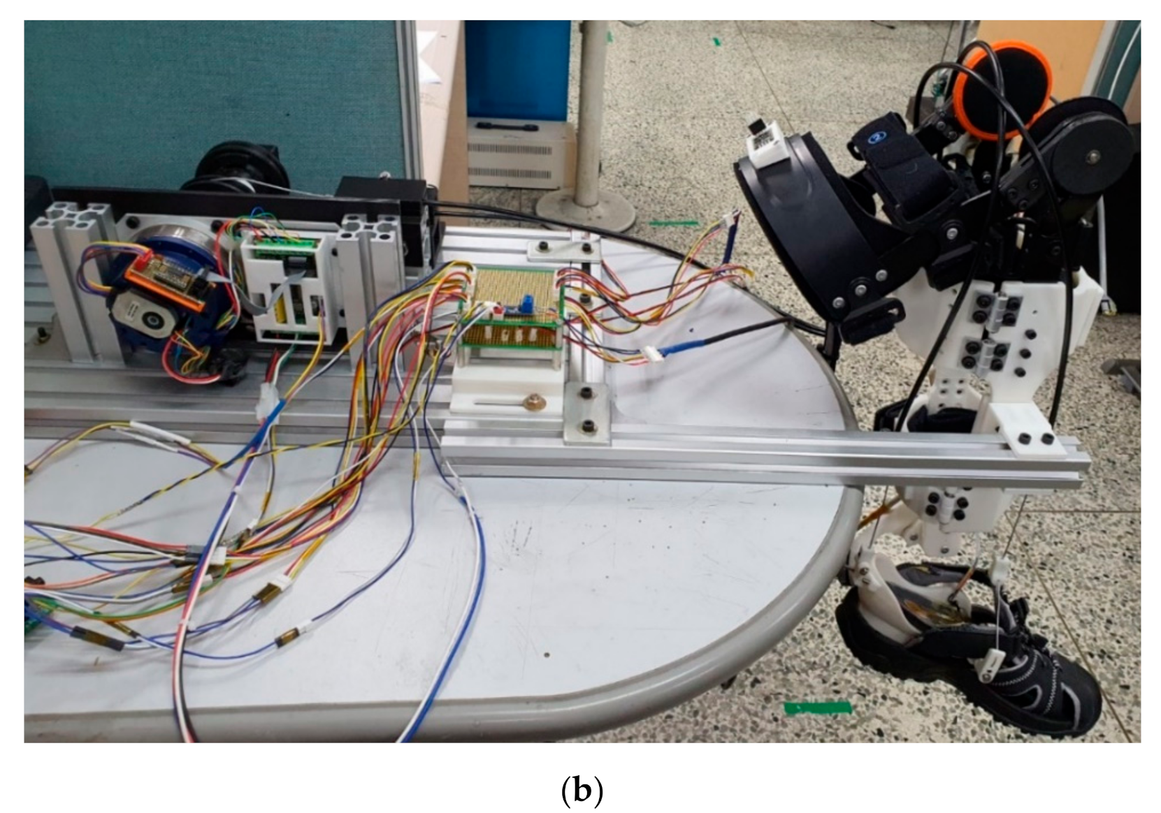
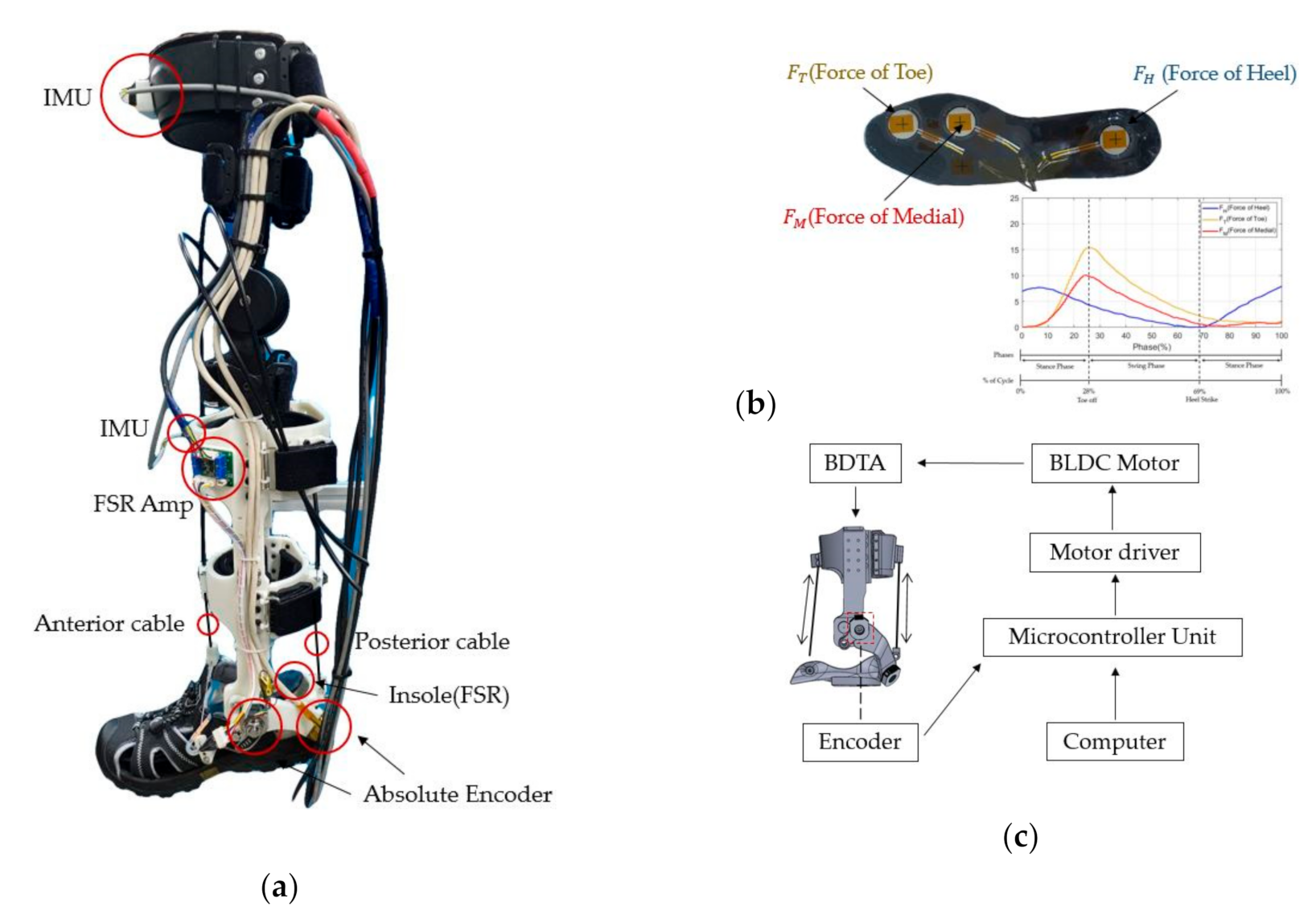
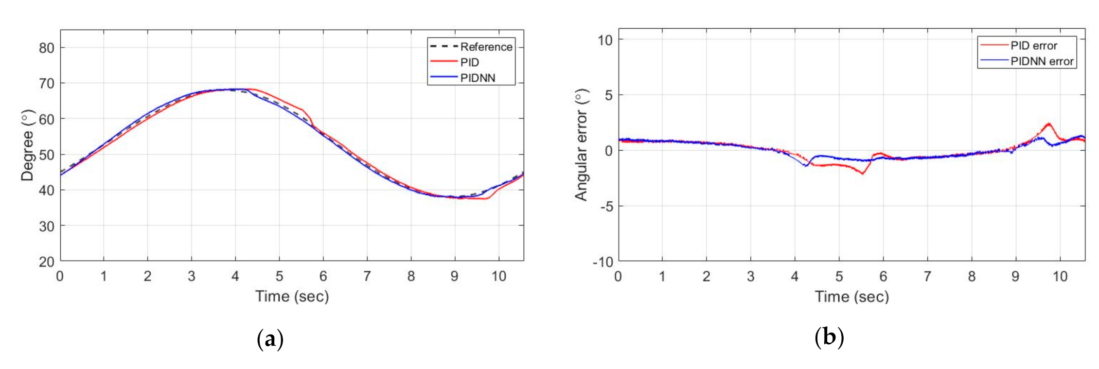
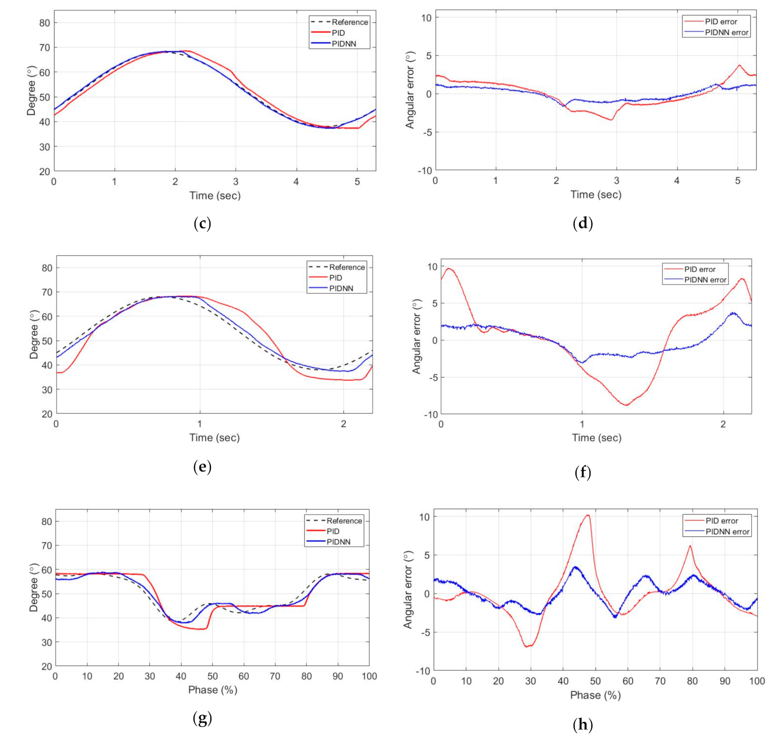
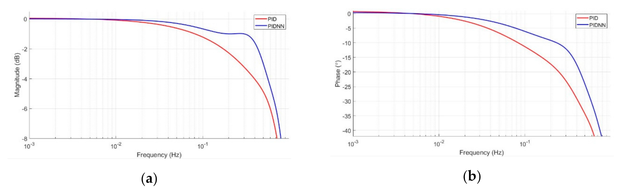
5. Experimental Setting and Results

As shown in Figure 10 and Figure 11, IMU sensors were attached to the center of the shin and thighs of the developed 2DoF ankle exoskeleton robot. The IMU sensor can estimate the angle of rotation of the ankle based on data from the gyroscope and accelerometer while walking. A pressure sensor (force-sensing resistor, FSR), was attached to the insole in the sole part. The three FSR sensors were located at each point in the toe, heel, and medial of the insole, and, when walking, the toe-off point and the heel strike point due to foot pressure could be detected and the walking section could be identified. The anterior cable was connected to the center of the instep, and the posterior cable was connected to the center of the heel. An encoder was attached to each part to measure the rotation angle of the talocrural joint and subtalar joint of the ankle during walking. The actuator included an electric motor (TBM (S) -6013-B, KOLLMORGEN, Tianjin, China), gear reducer (100:1, SHD-20-2SH, Harmonic Drive LLC, San Jose, CA, USA), encoder (AMT 203-V (Absolute), CUI Inc., Gyeonggi-do, Korea), IMU (EBIMU-9DOFV5, E2BOX Inc., Shanghai, China), and motor driver (24V-16A, CUBE-BL2416-SIH, Robocube Tech co., Gyeonggi-do, Korea). The STM32F4 Discovery board communicated with the motor driver via a controller area network (CAN).
The experimental setup was used by attaching an ankle exoskeleton robot to the rigid body, as shown in Figure 10 and Figure 11, to validate the proposed controller. When the input angle of the sinusoidal was given, the angle value of the talocrural joint was set to follow. The sinusoidal angle was set from 38° to 68° in consideration of the angle value of the talocrural joint during walking so that the joint moved at 30°. The micro controller unit (MCU) interrupt time was one millisecond. The motor was set to a maximum of 3000 rpm in consideration of the maximum allowable speed. The input frequency was changed to check the drive capability for angle tracking. Experiments were conducted for frequencies of 0.1 Hz, 0.2 Hz, and 0.4 Hz. In addition, to verify the performance required for rehabilitation, an experiment was conducted on the walking pattern received at a walking speed of 1 km/h on the treadmill. To improve the subsequent response to the controller, gain tuning was performed, and an experiment was conducted with optimal parameters. Table 2 and Table 3 show the PID control and PIDNN control parameter values for each experiment.
As can be seen in Figure 12, the maximum error at the sinusoidal frequency of 0.1 Hz was about 2.5° for PID and 1.3° for the PIDNN. Additionally, at 0.2 Hz, PID was about 4° and the PIDNN was about 1.5°, and at 0.4Hz, PID was about 9.2° and the PIDNN was about 3.6°. As the frequency of sinusoidal increased, the position tracking error of PID gradually increased, but PIDNN showed a relatively stable appearance. In particular, when PID increased from 0.2 Hz to 0.4 Hz, the position tracking error rapidly increased in the rotation section. In addition, in the experiment with the walking pattern of 1 km/h, the PID was about 10.2°, and the PIDNN had an error of about 4°. The error decreased as the learning rate of the PIDNN controller increased from 0.1 to 0.3. However, performance deteriorated above 0.4. Figure 13 is a bode plot obtained by the Fourier curve fitting the magnitude and phase data for each frequency. The point on the talocrural axis of the ankle exoskeleton robot was 61.45 mm from the origin. At that point, the z-axis movement of the talocrural joint moved about 17 mm down for dorsiflexion and 5 mm up for plantar flexion. Therefore, the length of the ground of the polycentric structure was 22.54 mm, so the ICR was designed to move within the same range. Therefore, when the DF and PF of the ankle moved, they followed the axis of the ankle.

6. Discussion

In this paper, a 2DoF ankle exoskeleton robot that matched the actual axis of the ankle was designed, and a polycentric structure was applied to minimize misalignment in the talocrural joint according to the movement of the ankle. The relative angles of the tibia and talus were calculated using an encoder connected to the polycentric structure. At a walking speed of 1 km/h, a range of about 20° was measured for the relative angle. To solve the misalignment caused by the ankle joint not rotating in one center, the change in length of the anterior and posterior cables according to the rotation of the talocrural joint and the subtalar joint was calculated. The length change of the cable was about 20 mm larger for the posterior cable than for the anterior cable. Therefore, the pully connected to the anterior cable was designed to be able to change the length by about 20 mm by inserting a spring, and the pully connected to the posterior cable to provide propulsion when walking was applied with a series elastic system to ensure system stability under strong torque.
PID neural network control was applied to solve the uncertainty of the developed exoskeleton robot. To verify the applied PID neural network controller performance, it was compared with the PID controller. The experimental results showed that the PID neural network reduced errors. As shown in Figure 13, when considering the stability of the system, the cutoff frequency at the −3 dB point was 0.27 Hz for the PID and 0.51 Hz for the PIDNN. Accordingly, in the walking pattern with a frequency of 0.45 Hz, the PID was not satisfied with the stability of the system and indicated that movement may be disturbed. Therefore, it was shown that both the PID and PIDNN were suitable for simple repetitive rehabilitation training with a sinusoidal frequency of about 0.2 Hz, but the PIDNN was more suitable because the PID could not accurately follow a gait pattern in which the ankle movement was rapid. At a frequency of 0.2 Hz, there was no significant difference in performance, but a real person wearing an exoskeleton robot could increase the uncertainty of the system. In this case, a PIDNN could be expected to perform better by using a variable to resolve the system uncertainty due to the error value.
We found that the BTDA system with the PIDNN controller performed differently depending on the designed parameters. The PIDNN controller showed a difference in performance depending on the learning rate, rather than the PID. As the learning rate increased, the errors decreased. However, if the learning rate increased significantly more than a certain value, the system became unstable, and errors increased. Therefore, it is important to determine the appropriate learning rate after finding the optimal PID gain.

7. Conclusions and Future Work

In this paper, we explored the development of mechanisms for exoskeleton robots and the design and control of actuators. Research on misalignment in ankle exoskeleton robots is currently limited. The talocrural joint of the ankle is tilted downward during dorsiflexion and upward during plantar flexion, thereby changing the ICR. This movement is similar to that of the Chebyshev linkage, a four-bar linkage system, which can follow changes in the ICR of the talocrural joint. Therefore, to minimize misalignment and increase the wearer’s stability, we proposed applying a polycentric structure to the ankle structure of an exoskeleton robot. The polycentric structure has difficulty in estimating the actual ankle angle, therefore an encoder was connected to one axis of the polycentric structure to estimate the relative angle of the tibia and talus in the actual human body. The ankle is located under the body, and the BTDA was designed to control the actuator by placing it above the body for the wearer’s stability. The BTDA was designed to address the length change to minimize misalignment due to the difference in length changes of both cables, which is required for bidirectional control. The developed exoskeleton robot controlled the ankle structure of the 2DoF with a four-bar linkage structure with only one axis, thus it could not be fully controlled, resulting in system uncertainty. In addition, mechanical uncertainty arises because the system is controlled with a relatively flexible cable rather than the fixed actuators commonly used in this type of system. To minimize this uncertainty and ensure the wearer’s stability, we applied an artificial neural network-based PID controller. The PIDNN controller showed a difference in performance according to the learning rate than PID. The error decreased as the learning rate increased, but the performance deteriorated above a certain value. Therefore, it was necessary to determine the learning rate after finding the optimum PID gain value. The PID controller system became unstable as the frequency of sinusoidal increased, but the PIDNN controller was relatively stable. The PIDNN controller was designed to solve the parameters and nonlinearities using the mathematical simplicity of the PID controller, and the function of the artificial neural network. Therefore, the developed BTDA is thought to greatly contribute to the development of an ankle exoskeleton robot.
In future, an actuator that is currently being developed for experimentation will be further developed to be worn on the waist. In addition, the ankle exoskeleton robot can help only when the wearer’s intention to walk is identified. Therefore, because it is difficult for ankle patients to infer the angle of the ankle, the three-axis accelerometer data and three-axis gyroscope data are measured with two IMU sensors attached to the 2DoF ankle exoskeleton robot. Based on the measured data, a study that estimates the angle of the ankle in real-time when walking through AI calculation could support further development of this technology.

Author Contributions

T.L. contributed to conceptualization, designed the exoskeleton, actuator, and controller; T.L. and I.K. undertook the writing, formal analysis, investigation, and validation; Y.S.B. performed funding acquisition, project administration, and supervision. All authors have read and agreed to the published version of the manuscript.

Funding

This research received no external funding.

Institutional Review Board Statement

Not applicable.

Informed Consent Statement

Not applicable.

Data Availability Statement

Data is contained within the article.

Conflicts of Interest

The authors declare no conflict of interest.

References

  1. Blank, A.A.; French, J.A.; Pehlivan, A.U.; O’Malley, M.K. Current Trends in Robot-Assisted Upper-Limb Stroke Rehabilitation: Promoting Patient Engagement in Therapy. Curr. Phys. Med. Rehabil. Rep. 2014, 2, 184–195. [Google Scholar] [CrossRef] [PubMed]
  2. Dzahir, M.A.M.; Yamamoto, S.-I. Recent Trends in Lower-Limb Robotic Rehabilitation Orthosis: Control Scheme and Strategy for Pneumatic Muscle Actuated Gait Trainers. Robotics 2014, 3, 120–148. [Google Scholar] [CrossRef] [Green Version]
  3. Veale, A.J.; Xie, S.Q. Towards compliant and wearable robotic orthoses: A review of current and emerging actuator technologies. Med Eng. Phys. 2016, 38, 317–325. [Google Scholar] [CrossRef]
  4. United Nations, Department of Economic and Social A_airs. Available online: https://www.un.org/en/development/desa/population/publications/pdf/ageing/WPA2017_Highlights.pdf (accessed on 4 January 2021).
  5. Pirker, W.; Katzenschlager, R. Gait disorders in adults and the elderly. Wien. Klin. Wochenschr. 2017, 129, 81–95. [Google Scholar] [CrossRef] [PubMed] [Green Version]
  6. Nef, T.; Mihelj, M.; Kiefer, G.; Perndl, C.; Muller, R.; Riener, R. ARMin—Exoskeleton for Arm Therapy in Stroke Patients. In Proceedings of the 2007 IEEE 10th International Conference on Rehabilitation Robotics, Noordwijk, The Netherlands, 13–15 June 2007; pp. 68–74. [Google Scholar]
  7. Visintin, M.; Barbeau, H.; Korner-Bitensky, N.; Mayo, N.E. A New Approach to Retrain Gait in Stroke Patients Through Body Weight Support and Treadmill Stimulation. Stroke 1998, 29, 1122–1128. [Google Scholar] [CrossRef] [Green Version]
  8. Isman, R.E.; Inman, V.T.; Poor, P.M. Anthropometric studies of the human foot and ankle. Bull Prosthet Res. 1969, 11, 129. [Google Scholar]
  9. Brockett, C.L.; Chapman, G.J. Biomechanics of the ankle. Orthop. Trauma 2016, 30, 232–238. [Google Scholar] [CrossRef] [Green Version]
  10. Alexander, N.B.; Goldberg, A. Gait disorders: Search for multiple causes. Clevel. Clin. J. Med. 2005, 72, 586. [Google Scholar] [CrossRef]
  11. Morgenroth, D.C.; Orendurff, M.S.; Shakir, A.; Segal, A.; Shofer, J.; Czerniecki, J.M. The Relationship Between Lumbar Spine Kinematics during Gait and Low-Back Pain in Transfemoral Amputees. Am. J. Phys. Med. Rehabil. 2010, 89, 635–643. [Google Scholar] [CrossRef]
  12. Kerrigan, D.C.; Frates, E.P.; Rogan, S.; Riley, P.O. Hip hiking and circumduction: Quantitative definitions. Am. J. Phys. Med. Rehabil. 2000, 79, 247–252. [Google Scholar] [CrossRef]
  13. Miao, Q.; Zhang, M.; Wang, C.; Li, H. Towards Optimal Platform-Based Robot Design for Ankle Rehabilitation: The State of the Art and Future Prospects. J. Heal. Eng. 2018, 2018, 1–9. [Google Scholar] [CrossRef]
  14. Asbeck, A.T.; De Rossi, S.M.; Holt, K.G.; Walsh, C.J. A biologically inspired soft exosuit for walking assistance. Int. J. Robot. Res. 2015, 34, 744–762. [Google Scholar] [CrossRef]
  15. Galle, S.; Malcolm, P.; Collins, S.H.; De Clercq, D. Reducing the metabolic cost of walking with an ankle exoskeleton: Interaction between actuation timing and power. J. Neuroeng. Rehabil. 2017, 14, 1–16. [Google Scholar] [CrossRef]
  16. Wiggin, M.B.; Sawicki, G.S.; Collins, S.H. An exoskeleton using controlled energy storage and release to aid ankle propulsion. In Proceedings of the 2011 IEEE International Conference on Rehabilitation Robotics, Zurich, Switzerland, 29 June–1 July 2011; pp. 1–5. [Google Scholar]
  17. Van Dijk, W.; Meijneke, C.; Van Der Kooij, H. Evaluation of the Achilles ankle exoskeleton. IEEE Trans. Neural Syst. Rehabil. Eng. 2016, 25, 151–160. [Google Scholar] [CrossRef] [PubMed] [Green Version]
  18. Gordon, K.E.; Ferris, D.P. Learning to walk with a robotic ankle exoskeleton. J. Biomech. 2007, 40, 2636–2644. [Google Scholar] [CrossRef] [PubMed]
  19. Bae, J.; Siviy, C.; Rouleau, M.; Menard, N.; O’Donnell, K.; Geliana, I.; Athanassiu, M.; Ryan, D.; Bibeau, C.; Sloot, L.; et al. A Lightweight and Efficient Portable Soft Exosuit for Paretic Ankle Assistance in Walking After Stroke. In Proceedings of the 2018 IEEE International Conference on Robotics and Automation (ICRA), Brisbane, QLD, Australia, 21–25 May 2018; pp. 2820–2827. [Google Scholar]
  20. Lerner, Z.F.; Harvey, T.A.; Lawson, J.L. A battery-powered ankle exoskeleton improves gait mechanics in a feasibility study of individuals with cerebral palsy. Annals Biomed. Eng. 2019, 47, 1345–1356. [Google Scholar] [CrossRef] [PubMed]
  21. Bartenbach, V.; Gort, M.; Riener, R. Concept and design of a modular lower limb exoskeleton. In Proceedings of the 2016 6th IEEE International Conference on Biomedical Robotics and Biomechatronics (BioRob), Singapore, 26–29 June 2016; pp. 649–654. [Google Scholar]
  22. Hyun, D.J.; Park, H.; Ha, T.; Park, S.; Jung, K. Biomechanical design of an agile, electricity-powered lower-limb exoskeleton for weight-bearing assistance. Robot. Auton. Syst. 2017, 95, 181–195. [Google Scholar] [CrossRef]
  23. Moltedo, M.; Baček, T.; Verstraten, T.; Rodriguez-Guerrero, C.; Vanderborght, B.; Lefeber, D. Powered ankle-foot orthoses: The effects of the assistance on healthy and impaired users while walking. J. NeuroEng. Rehabil. 2018, 15, 86. [Google Scholar] [CrossRef]
  24. Beil, J.; Marquardt, C.; Asfour, T. Self-aligning exoskeleton hip joint: Kinematic design with five revolute, three prismatic and one ball joint. In Proceedings of the 2017 International Conference on Rehabilitation Robotics (ICORR), London, UK, 17–20 July 2017; pp. 1349–1355. [Google Scholar]
  25. Beil, J.; Asfour, T. New mechanism for a 3 DOF exoskeleton hip joint with five revolute and two prismatic joints. In Proceedings of the 2016 6th IEEE International Conference on Biomedical Robotics and Biomechatronics (BioRob), Singapore, 26–29 June 2016; pp. 787–792. [Google Scholar]
  26. Lee, T.; Lee, D.; Song, B.; Baek, Y.S. Design and Control of a Polycentric Knee Exoskeleton Using an Electro-Hydraulic Actuator. Sensors 2019, 20, 211. [Google Scholar] [CrossRef] [Green Version]
  27. Choi, H.S.; Lee, C.H.; Baek, Y.S. Design of a Pneumatic Actuated Ankle-Foot Orthosis which has Talocrural and Subtalar Joint. In Proceedings of the 2019 IEEE 16th International Conference on Rehabilitation Robotics (ICORR), Toronto, ON, Canada, 24–28 June 2019; pp. 276–281. [Google Scholar]
  28. Lundberg, A.; Svensson, O.; Nemeth, G.; Selvik, G. The axis of rotation of the ankle joint. J. Bone Jt. Surgery. Br. Vol. 1989, 71, 94–99. [Google Scholar] [CrossRef]
  29. Lundberg, A. Kinematics of the ankle and foot: In vivo roentgen stereophotogrammetry. Acta Orthop. Scand. 1989, 60, 1–26. [Google Scholar] [CrossRef] [Green Version]
  30. Fatone, S.; Hansen, A.H. A Model to Predict the Effect of Ankle Joint Misalignment on Calf Band Movement in Ankle-Foot Orthoses. Prosthetics Orthot. Int. 2007, 31, 76–87. [Google Scholar] [CrossRef] [PubMed] [Green Version]
  31. Sumiya, T.; Suzuki, Y.; Kasahara, T.; Ogata, H. Instantaneous centers of rotation in dorsi/plantar flexion movements of posterior-type plastic ankle-foot orthoses. J. Rehabil. Res. Dev. 1997, 34, 279. [Google Scholar] [PubMed]
  32. Tzu-wei, P.H.; Kuo, A.D. Mechanics and energetics of load carriage during human walking. J. Exp. Biol. 2014, 217, 605–613. [Google Scholar]
  33. Kumpati, S.N.; Kannan, P. Identification and control of dynamical systems using neural networks. IEEE Trans. Neural Netw. 1990, 1, 4–27. [Google Scholar]
  34. Shu, H.; Pi, Y. PID neural networks for time-delay systems. Comput. Chem. Eng. 2000, 24, 859–862. [Google Scholar] [CrossRef]
  35. Yongquan, Y.; Ying, H.; Bi, Z. A PID neural network controller. In Proceedings of the International Joint Conference on Neural Networks, Portland, OR, USA, 24–27 July 2003; pp. 1933–1938. [Google Scholar]
  36. Kumar, R.; Srivastava, S.; Gupta, J.R. Artificial neural network based PID controller for online control of dynamical systems. In Proceedings of the 2016 IEEE 1st International Conference on Power Electronics, Intelligent Control and Energy Systems (ICPEICES), Delhi, India, 4–6 July 2016; pp. 1–6. [Google Scholar]
  37. Kim, J.-H.; Shim, M.; Ahn, D.H.; Son, B.J.; Kim, S.-Y.; Kim, D.Y.; Baek, Y.S.; Cho, B.-K. Design of a Knee Exoskeleton Using Foot Pressure and Knee Torque Sensors. Int. J. Adv. Robot. Syst. 2015, 12, 112. [Google Scholar] [CrossRef]
  38. Bapat, G.M.; Sujatha, S. A Method for Optimal Synthesis of a Biomimetic Four-Bar Linkage Knee Joint for a Knee-Ankle-Foot Orthosis. J. Biomimetics, Biomater. Biomed. Eng. 2017, 32, 20–28. [Google Scholar] [CrossRef]
  39. Donatelli, R. Normal Biomechanics of the Foot and Ankle. J. Orthop. Sports Phys. Ther. 1985, 7, 91–95. [Google Scholar] [CrossRef]
  40. Murray, M.P.; Drought, A.B.; Kory, R.C. Walking Patterns of Normal Men. IJBS 1964, 46, 335–360. [Google Scholar] [CrossRef]
  41. Piña, E. Rotations with Rodrigues’ vector. Eur. J. Phys. 2011, 32, 1171. [Google Scholar] [CrossRef]
  42. Grimmer, M.; Seyfarth, A. Mimicking human-like leg function in prosthetic limbs. In Neuro-Robotics; Springer: Dordrecht, The Netherlands, 2014; pp. 105–155. [Google Scholar]
  43. Pratt, J.E.; Krupp, B.T. Series elastic actuators for legged robots. In Unmanned Ground Vehicle Technology Vi; International Society for Optics and Photonics: Orlando, FL, USA, 2004; pp. 135–144. [Google Scholar]
Figure 1. Overview of ankle anatomy and four-bar linkage: (a) anatomical structure of the human ankle, and talocrural joint position changes according to dorsiflexion (DF) and plantar flexion (PF); (b) Instantaneous center of rotation (ICR) position change according to the movement of the four-bar linkage.
Actuators 10 00009 g001
Figure 2. Design of the developed two degrees of freedom (2DoF) ankle exoskeleton robot and design of the ankle structure: (a) a 2DoF ankle exoskeleton robot with a polycentric structure in the talocrural joint.; (b) each part is responsible for the function of the ankle. Part A is the tibia, Part B is the talus, and Part C is the sole.
Actuators 10 00009 g002
Figure 3. Ankle structure movement and gait data: (a) polycentric structure movement according to the movement of both cables; (b) the encoder date of the ankle joint obtained during the gait.
Actuators 10 00009 g003
Figure 4. 2DoF ankle exoskeleton showing the location of the cable origin, the insertion points, and the subtalar axis.
Actuators 10 00009 g004
Figure 5. The changes in cable length were calculated based on the rotation angle of the talocrural joint and subtalar joint in Figure 3b. Observing the black line, the posterior cable has a longer length change than the anterior cable.
Actuators 10 00009 g005
Figure 6. Designed bidirectional tendon-driven actuator (BTDA): (a) cable movement direction according to the motor rotation direction; (b) pulley connected to the anterior cable. d is the compressible spring length.
Actuators 10 00009 g006
Figure 7. Structure of the Proportional-Integral-Differential Neural Network (PIDNN) controller.
Actuators 10 00009 g007
Figure 8. Schematic diagram of the PID neural network (PIDNN) controller back-propagation.
Actuators 10 00009 g008
Figure 9. Schematic block diagram of the ankle exoskeleton controller.
Actuators 10 00009 g009
Figure 10. The experimental setup: (a) bi-directional tendon-driven actuator, microcontroller unit, controller area network, brushless direct current motor and motor driver for motor control; (b) The overall experimental setup attached to a rigid body.
Actuators 10 00009 g010aActuators 10 00009 g010b
Figure 11. Overall 2DoF ankle exoskeleton robot: (a) sensor location attached to the exoskeleton robot (encoder, inertial measurement unit (IMU), force-sensing resistor (FSR)); (b) foot sensor for measuring the gait step; (c) a schematic representation of the experimental setup.
Actuators 10 00009 g011
Figure 12. Experimental results of the PID Neural Network control (PIDNN) and PID control: (a,c,e,g) Results of the angular position estimation performance; (b,d,f,h) Results of the angle tracking error. (From top to bottom, 0.1 Hz, 0.2 Hz, 0.4 Hz, walking pattern).
Actuators 10 00009 g012aActuators 10 00009 g012b
Figure 13. Driving capacity as frequency changes: (a) magnitude variation in angle tracking; (b) phase variation in angle tracking.
Actuators 10 00009 g013
Table 1. The parameter values of the polycentric structure.
ParameterSpecification (mm)
l 1 32
l 2 22.54
l 3 32
l 4 22.54
D 17.1
P 5.44
Table 2. Controller parameter at the frequency of each sinusoidal ( η = learning rate).
FrequencyPID GainPIDNN Gain
0.1 Hz K p = 20 ,     K i = 0.001 ,     K d = 0.1 K p = 20 ,     K i = 0.001 ,     K d = 0.1 ,   η = 0.2
0.2 Hz K p = 40 ,     K i = 0.001 ,     K d = 0.1 K p = 40 ,     K i = 0.001 ,     K d = 0.1 ,   η = 0.2
0.4 Hz K p = 80 ,     K i = 0.001 ,     K d = 0.2 K p = 80 ,     K i = 0.001 ,     K d = 0.2 ,   η = 0.3
Table 3. Controller parameter in the walking pattern of 1 km/h ( η = learning rate).
Walking
Pattern
PID GainPIDNN Gain
1 km/h K p = 90 ,     K i = 0.001 ,
  K d = 0.2
K p = 90 ,   K i = 0.001 ,   K d = 0.2 ,
  η = 0.3
Publisher’s Note: MDPI stays neutral with regard to jurisdictional claims in published maps and institutional affiliations.

