1. Introduction
Miniaturized end-effectors or “Microgrippers” located at the end of a robotic arm are primarily designed based on the complexity of the task for which the robot would be used. Different robotic actions that would require different designs include some fundamental manipulation processes such as grasping, placing, pushing, blowing, clamping, cutting, stapling and squeezing. In general, possible concept of end-effector can be obtained from passive and active structures that are designed to handle a set of tasks. In recent years, there is a growing demand to develop MicroElectroMechanical System (MEMS) end-effectors that are capable of handling and manipulating various micrcomponents for microassembly. Such MEMS structures could be potentially adapted for non-conventional endoscopic surgeries that require precision and delicate operations. Electrothermal (E-T) actuation based on asymmetrical thermal expansion has popularly been applied to generate both the large force and deflection using structures such as bent beam and folded beam actuators [
1,
2,
3,
4,
5,
6,
7,
8].
Microstructures based on an array of thermal actuators provide powerful force and wide overall deflection [
9,
10,
11]. A class of new active end-effectors based on an E-T actuation principle was introduced in our earlier work [
7,
11]. The performance of E-T actuators is limited by the maximum operating temperature and thermal stresses [
12,
13,
14]. The coupling of “E-T to structural” is much stronger than the “structural to E-T” coupling. Thus, configuration and loading conditions of a micromachined material can independently determine the temperature profile at steady state.
E-T microstructures can be classified according to their release into three types [
8]; overhanging (
released or totally exposed to ambient), suspended (or the structure is separated
by an air gap from substrate) and attached (or
physically attached to substrate) microstructures. They can be fabricated from different materials using various technologies including Silicon on Insulator, SU8, and MUMPs [
7]. The multi physics simulation of thermal MEMS actuators is often obtained from Finite Element Modeling (FEM) or Finite Element Approximation (FEA). Lerch
et al. have studied the temperature distribution and deflection of a microstructure using a Finite Element (FE) analysis [
12]. Lin and Chiao have used FE simulation to study the E-T response of a line-shape microstructure [
8]. Mankame introduced a comprehensive thermal model for the FE simulation of E-T compliant structure [
2]. However, analytical solutions provide more flexibility and physical insight, and facilitate a designer to explore additional constraints of failure, including potential melting which might be difficult to predict using FEA simulation due to the approximation algorithms used. Also, the analytical thermal models were previously obtained only for a few conditions focusing on low power E-T actuators.
This paper presents comprehensive analytical E-T models that are obtained at a range of control input conditions for different ElectroThermoElastic microstructures. Temperature profiles at steady state of hanging and overhanging line-shape microstructures will be derived for layout combining bent and/or folded beams. Numerical simulations are obtained to support the analytical solutions. The structure of this paper is as follows: we start with practical examples of electrothermoealstic microstructures to motivate the reader with the possible application areas. Then, we introduce a reduced thermal model for the steady state heat conduction equation of a microstructure. Closed form expressions are obtained for configurations under several boundary conditions and power inputs, including suspended to overhanging microstructures. Finally, we compare the analytical solution with simulation results from finite element modeling and experimental findings.
3. Steady-State Thermal Modeling
The microstructures could be fabricated from a single micromachined layer, and they can be modeled as a set of microbeams connected in series and/or parallel. In most fabricated MEMS actuators, microbeams are mostly rectangular bars of different widths and lengths and of uniform heights. The thermal response of (n) sequentially connected microbeams of different widths is sensitive to the air gap between the device and the substrate. Thus, the temperature profile along microbeams in an overhanging microstructure must be treated in a different way to those microstructures which are separated with air gaps.
In general, the temperature variation (
T) along a microstructure (
x) is governed by a nonlinear one dimensional Partial Differential Equation (PDE) with an input energy source from current (
I) whose density along microbeam is (
J =
I/wh) [
6,
7,
13]. A suspended rectangular bar with width
w and height (
h) is kept at a fixed air gap distance relative to the substrate. The rate of heat change per unit area is equal to the heat production per unit volume (
A.dx) per time minus heat losses, or [
7]
Equation (1) is a general 1-D transient heat conduction that combines the nonlinearity of heat conduction coefficient and the effect of radiation heat transfer. Convection coefficients (hcs) and hcu correspond to the thermal convection heat losses off the side wall and the faces of microbeams, respectively. λ is a numeric factor introduced here to describe the heat loss condition. (λ) is equal to one when heat conduction through air gap is considered. However, (λ) is two when microbeams are experiencing convection from all sides with no conduction to other layers, i.e., shape factor (S) is zero. ρd and Cp are material density and specific heat of actuator, respectively. The resistivity of microbeam (ρr) is linearly dependent on temperature. The thermal conductivity of the actuator material (kp(T)) will be later assumed constant. (Tp, Ta and Tb) are constant temperatures of the bottom surface of the substrate, ambient and of a black body, respectively. All are assumed here to be equal to some constant temperature (Ts). The nonlinear radiation term in Equation (1) is proportional to Stefan-Boltzmann constant (σ) and micro-surface emissivity (εe).
The shape factors of the heat conduction (
S) impacts the shape of the element on the excessive heat conduction to the substrate [
8]. A shape factor is defined by the total heat flux out of the line-shape microbeam per unit length divided by heat flux going directly under the width of a microbeam [
6,
8,
15]. It is given by
Few micrometer of air gap can be modeled as a conductive layer with zero Young’s Modulus and infinite electrical resistivity. (RT) is a thermal resistance between the thermal microbeam and the substrate. For microbeam suspended on two sandwiched layers, such as SOI, the thermal resistance is
where (tv) and (ts) are the air gap and substrate thicknesses, respectively. (kv) and (ks) are the thermal conductivity of the air and a substrate, respectively.
The electrical resistivity of microbeam is function of its temperature, and it is assumed to have a linear thermal coefficient (ξ), that is
Thermal conductivity (
kp) of silicon is generally dependent on temperature variation. It is generally approximated in a third order polynomial [
16]
where the non-constant terms add non linearity to the governing equation making the conductive structure to have higher and more sensitivity for temperature change.
Surface heat radiation by convection and radiation in small structures should be considered at high operating temperature, normally above 500 K [
2]. The radiation heat transfer is significant in suspended or separated structures which are experiencing high temperature difference at small gaps range between 1–10 µm [
8,
17]. To simplify Equation (1), the radiation term is dropped. Thermal conductivity is assumed to be temperature independent. The Steady State Heat Equation is obtained by dropping the time partial derivative in Equation (1) and reduces into second order ODE Equation (6a). The Eigen values of its characteristic equation determine the solution profile. In general, for
n serially connected microbeams, the temperature profile is determined by the flowing critical current (
I(i)) or (
β(i)) value, and it is obtained from the roots of the characteristic equation of the ODE
After arranging the eigenvalues and substituting Equations (2), (3), (5) in Equation (6a), we get
This criterion is a property of a microstructure that determines the temperature profile when compared to the current flow I. The subscript (i) refers to the beam number or name in n-serially connected beams.
3.1. Folded or Bent Beam E-T Actuators
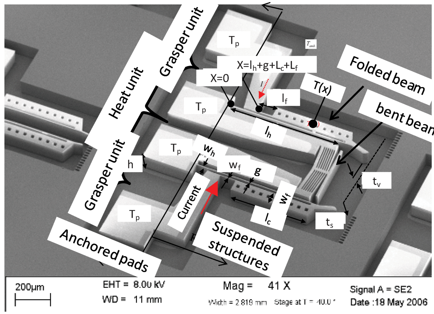
A single layer folded beam actuator in
Figure 2 has three serially connected micobeams(
n =
3). Its temperature distribution (
T(
x)) is continuous; starts from an anchored pad at (
x =
0), passes through a hot arm (
subscript h)
, then through cold arm (
subscript c)
, then flexure arm (
subscript f), and ends up to another anchored pad at (
x =
lh + g + lc + lf). The total number of boundary conditions needed to solve the unknown constants is
2n.
Figure 2.
The E-T actuator comprises a grasping mechanism and a heating element.
Figure 2.
The E-T actuator comprises a grasping mechanism and a heating element.
Case 1. Suspended microstructures with exponential profiles when (Ih, Ic and If < I)
The exponential temperature profiles, which normally take place at considerably low input voltage, have been discussed before and will be reviewed in this paper for completeness [
14]. The temperature profile along the microbeams is defined by an exponential function given that (
βh,
βc, βf > 0);
i.e., the input current is greater than the right hand side in Equation (6) or (
Ih,
Ic and
If < 1). The line-shape temperature profiles along each beam is
where T ∞i = (Tp + Ji2ρ0/βi). The temperature profile along the three connected microbeams is continuous. The unknown are solved from the continuity of temperature profile and heat flow. Applying the boundary conditions into the Steady State Heat Conduction Equation (SSHCE) gives the unknown constants (Cij)
Case 2. Suspended microstructures with mixed profiles when (Ih, If < I and Ic > I)
Mixed temperature profiles normally take place when the width of a cold arm in a folded beam actuator is larger than that of hot and flexure arms. This causes the exponential thermal responses in the hot and flexure arms to drift into a sinusoidal profile as the input current increases beyond the critical values. When (βh, βf < 0 and βc > 0), the temperature profiles of hot and flexure arms are given by
Case 3. Suspended microstructures with sinusoidal profiles when ((Ih, Ic and If) > I)
Sinusoidal response in all of the serially connected microbeams generally occurs at high input current. When (βh, βc, βf < 0) becomes true, the solution becomes
The “bent beam” model can be obtained from “folded beam” model with uniform width of wu. Where the equations derived in the above three cases can be used for “bent beam” given that wu = wh = wc = wf. For microbeams of the same width, the critical condition βh, βc, βf = 0 gives constant temperature profile Th (x) = Tc (x) = Tf (x) = Tp. In this case, the amount of heat generation is equal to the amount of heat lost across a substrate. There are only two cases in “bent beam” microstructures: (i) exponential profile which corresponds to low temperature; or (ii) sinusoidal profile pertaining high temperature response.
3.2. Combined Bent and Folded Beam Actuator
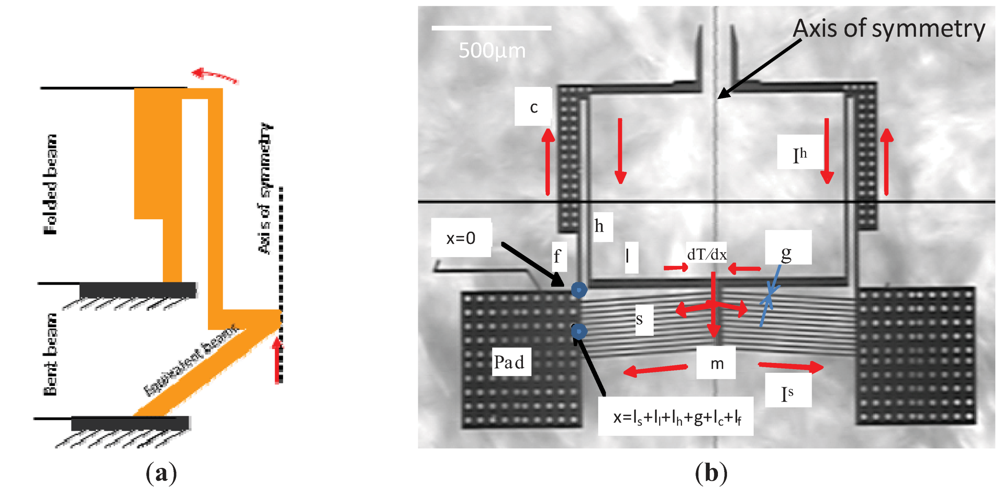
A different class of E-T actuator is obtained when the performances of the bent and folded beam are combined in a single microstructure. The grasper in
Figure 3 has two symmetrical structures with each having a series of connected microbeams. Each side starts from an anchored pad at (
x =
0), passes through bent beams (
subscript s), then a linkage arm (
subscript l), then a hot arm (
subscript h)
, then through a cold arm (
subscript c)
, then aflexure arm (
subscript f), and ends up to same anchored pad at (
x =
ls + ll + lh + g + lc + lf). The (
g) is the gap between the hot and cold arm. The current density across the hot arm, linkage arm, and bent beam causes high thermal expansion as compared to cold arm. Concurrently, the bent beams push the linkage arm forward. Thus, each tip in the grasper bends toward the cold arm with a greater overall all “opening and closing”.
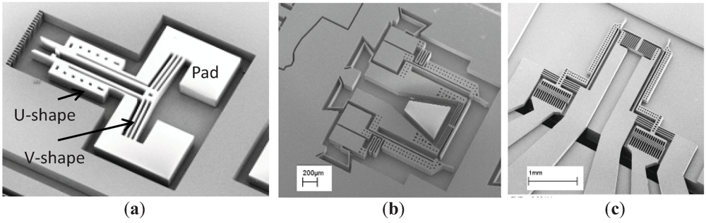
Figure 3.
Micro grasper combining folded and bent beam mechanisms: (a) sketch; (b) E-T actuator fabricated from SOI.
Figure 3.
Micro grasper combining folded and bent beam mechanisms: (a) sketch; (b) E-T actuator fabricated from SOI.
For this class of E-T actuator, the symmetry in the structure and the boundary conditions yield symmetrical temperature distribution about the “Axis of symmetry”, indicated in
Figure 3. The structure across this line is adiabatic where the temperature is at least local maximum. The temperature distribution along beams can be linearly solved in a line shape starting from one pad and ending at the same pad. The temperature’s drop due to the “middle link (
m)” electrical resistance could be neglected because the beam has short length. Thus, the temperatures difference across a parallel set of bent beams is assumed unchanged. It is sufficient to solve for temperature profile about one side of axis of thermal symmetry. The following cases are analogous to the previous discussion:
Case 1. Suspended microstructure with exponential profiles (If, Ic, Ih, Il, Is < I)
We consider E-T actuator whose device structure is suspended with an air gap separating it from the substrate. The temperature profile of a microstructure is governed by exponential steady state when (βf, βc, βh, βl, βs > 0) is hold. The temperature profile along microbeams is continuous, start from pad temperatures at a flexure arm and end up with same pad temperature at the end of bent beams. The temperature profiles are
The current passing through each beam is extracted from circuit analogy network. The current passing through the “folded beam” including flexure, cold, hot and linkage arm is
(Rs) and (Rh) are the overall electrical resistance of folded and bent beams in the microstructure, respectively. I is the total current drawn across the pad due to overall resistance, where I = Ih + Is and Is is the current passing in each one of the (q) bent beams
The electrical resistances are temperature dependent and their average can be simplified into
Thus, the voltage across the pads is
Alternatively, the resistances could be estimated from resistivity calculated at some close average temperature (ρa)
Case 2. Overhanging microstructure operating on ambient
The previous equation from Case 1 is valid for overhanging E-T actuators. The heat is lost to the ambient through natural convection, and the given the following criterion hold
This case is equivalent to the suspended E-T actuators which is described in Case 1 of
Section 3.1, but with large air gap,
i.e., the structure becomes overhanging. In such cases Equation (6b) can be replaced by Equation (17).
Case 3. Sinusoidal profiles
Temperature proliferates along structures in wavy profile. This occurs when one or both of the heat losses (
conduction through substrate or/and convection to ambient) are relatively lower than the generated heat. Subcases includes first, both suspended and overhanging microstructures in Cases 2 and 3 are operating at relatively high input current such that
![Actuators 01 00021 i022]()
. Second, E-T actuators is operating in vacuum with no heat losses where
βi =
![Actuators 01 00021 i024]() ρξ
ρξ and
T∞i =
T − 1/
ξ.
The governing equations yield sinusoidal profiles along all microstructures
Other cases might be obtained for mid-range input power, where the profiles combine exponential and sinusoidal shapes.
4. Simulation and Experimental Results
Finite Difference Method (FDA) and Finite Element Modeling (FEM) are compared with the exact solutions at different power input and boundary conditions. The FDA simulation is used to verify the mathematics of the exact expression with some degree of proximity. But it does not validate the exactness of the physical model. In FDA, the general solution of a rising temperature distribution could be obtained by Forward-Time Centered- Space method (FTCS). For E-T actuators with n-serially connected microstructures, the FDA of Equation (1) without heat radiation term can be written in a discrete format
where (ε = β/ψ0, ε > 0), (ω) and (χ) are integers that refer to the time and the space mesh, respectively. (Δx) and (Δt) are space and time grid resolution, respectively. Equation (19) is a general equation which can solve for any serially connected microstructures. The intermediate B.C’s between different microbeams are automatically embedded in the formula. Also, it can handle non-homogenous material and thickness properties across different microbeams. When an m parallel network of microbeam is introduced, a set of m n-serially connected equations must be solved simultaneously for the unknowns.
A physical model of a bent beam E-T actuator is used for comparison. The model is obtained for device layer fabricated on silicon substrate by deep reactive ion etching (DRIE) process on SOI wafers. The material properties and dimensions for a uniform width device layer are indicated in
Table 1, and listed in
Figure 4, respectively. The steady state temperature profiles for a single suspended bent beam E-T actuator are obtained from FEM, FDA and analytical model. FEM result is obtained from tetrahedral elements with polynomial based on second order expansion series. FEM and FDA are compared against analytical model for low and high power input. In the low power input, the exponential profile preserves the shape until 14 V. As the voltage increases the profile smoothly switches into sinusoidal keeping same profile shape. In both cases, the profiles maintain one local maximum at the beam center as indicated in
Figure 4. The FDA, FEM and Exact methods are all in good agreement for low and medium power input magnitude.
Table 1.
Material properties of SOI actuators.
Table 1.
Material properties of SOI actuators.
| SOI Layers Parameter | Si Device | Si wafer substrate | Air |
|---|
| Density, ρd (Kg/m3) | 2,330 | 2,330 | 0.524 |
| Thermal conductivity, (Wm−1 °C−1) | 100 | 30 | 3.37 × 10⁻² |
| Thermal Expansion, α (10−6 × °C−1) | 3.1 | 3.1 | 1.49 × 10³ |
| Thermal Capacity, Cp (J·Kg−1·°C−1) | 787 | 787 | 1,013 |
| Temperature coefficient, ξ (10−3 × °C−1) | 1.25 | 1.25 | - |
| Electrical resistivity, ρo (Ω·m) | 1.51 × 10⁻⁴ | 2.5 × 10⁻² | 3 × 10¹³ |
| Modulus of Elasticity, E (GPa) | 169 | 169 | - |
| Poison ratio, ν | 0.22 | 0.22 | - |
Figure 4.
Simulations of the temperature profile in a single bent beam.
Figure 4.
Simulations of the temperature profile in a single bent beam.
The steady state temperature profiles in of suspended folded beam actuator are simulated under no heat convection. The material properties and dimensions for a uniform width device layer are indicated in
Table 1, and listed in
Figure 5, respectively.
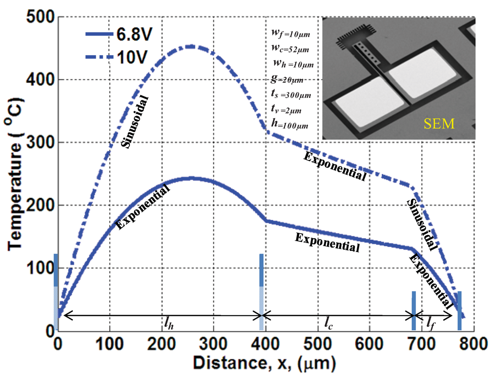
Figure 5 shows variation of temperature profile along beams. At low input power (6.8 V), the steady-state temperatures in all beams are exponentials. Increasing the input power up to 10 V has brought temperature response in thin-beams into sinusoidal. On the other hand, increasing the power input induces higher frequencies with multiple peaks across the microstructure. This type of response might be experimentally observed if the temperature-peaks do not exceed the melting point of the structure. It is worth to mention here that the approximation nature in finite element or finite difference element might not be sufficient to capture high temperature-peak fluctuation along microstructures.
Figure 5.
Simulations of the temperature profile in folded beam actuator.
Figure 5.
Simulations of the temperature profile in folded beam actuator.
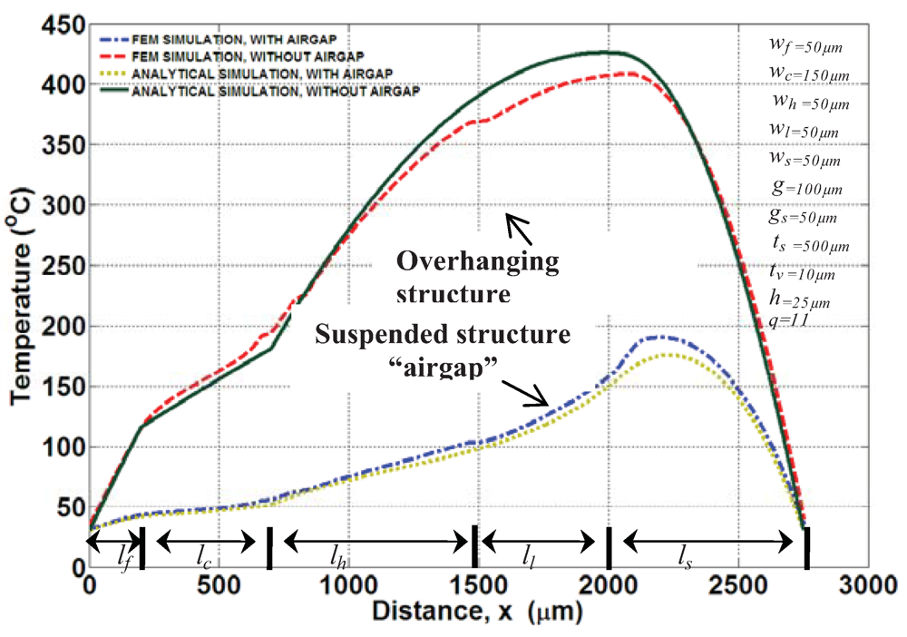
Figure 6.
Simulations of combined bent and folded beam actuator.
Figure 6.
Simulations of combined bent and folded beam actuator.
Examples on the steady state temperature profile of “combined bent beam and folded beams” are simulated for two types of actuators: overhanging and suspended structure similar to configuration in
Figure 3. The simulations are obtained at low power input of 1 V and at vacuum condition,
i.e., without heat convection.
Figure 6 shows the trend of the temperature profile which starts from flexure and ends up at the bent beam. The local maximum temperature is often located at the adiabatic line where the bent beams are connected to the linkage arm. The temperature profiles of suspended actuator have exponential responses along the entire microstructures. This is due to considerable heat loss through the conductive air gap. More increase in the air gap decreases heat loss and may bring the condition in Case 1 into either Case 2 or 3 as described in
Section 3.2. When the air gap is relatively large, the actuator becomes completely governed by sinusoidal profiles with significant increase in temperatures magnitude. We also notice that there is a slight difference between FEM and analytical result. One reason might be related to the averaging of thermal resistance. This has also led to a clear temperature difference between FEM and analytical around adiabatic line.
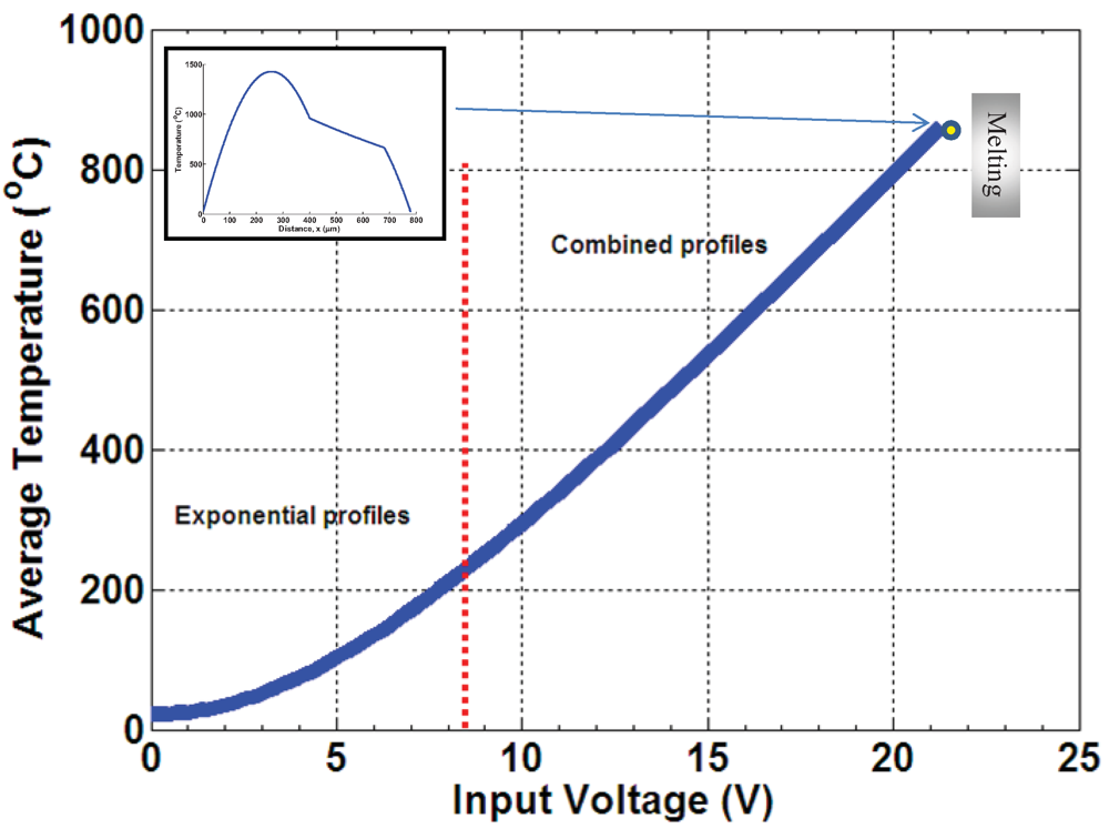
The continuity of the analytical models about the critical currents can be checked from the continuity of the average temperature over a range of input power. The overall average temperature for n-serially connected microbeams, whose length (lk) and temperature profile (Tk(x), lk ≥ x ≥ lk−1), can be lumped into
Figure 7 describes the continuity of temperature profiles over a range of input power for the dimension and materials in
Figure 5 and
Table 1, respectively. The simulation is stopped at average of ~860 °C where the material hypothetically fails due to melting (1,414 °C for silicon).
Figure 7.
Simulation of
![Actuators 01 00021 i023]()
in folded beam from analytical models.
Figure 7.
Simulation of
![Actuators 01 00021 i023]()
in folded beam from analytical models.
At about 8.3 V input, the average temperature is piece-wise smooth. The temperature profiles along the microstructures start to change from “exponential profiles” into “mixed profiles”, where the hot and flexure arms experience sinusoidal profiles while the cold arm maintains an exponential profile.
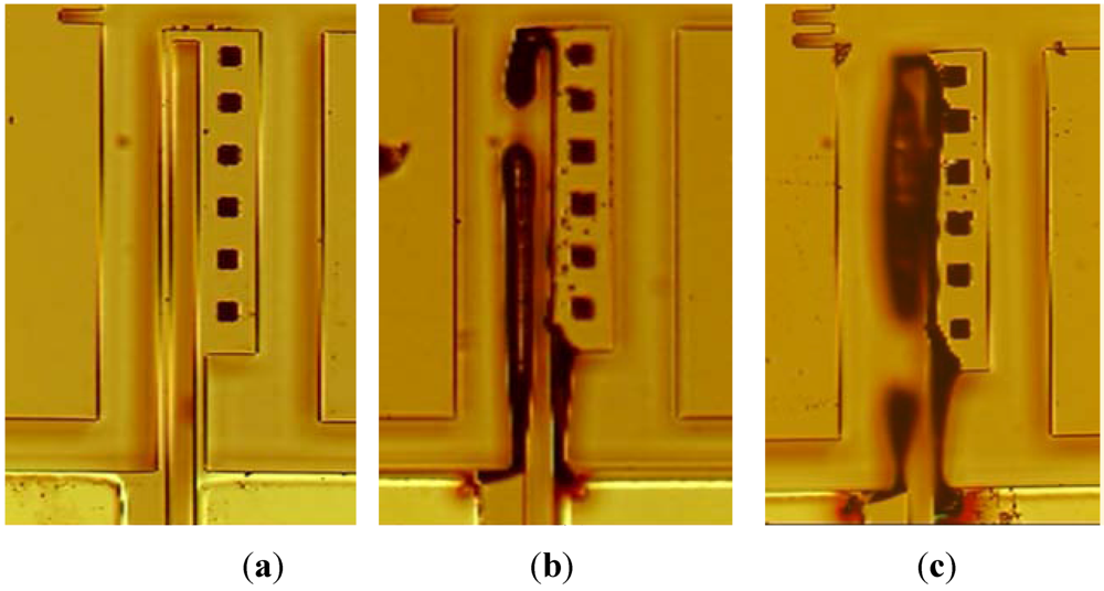
One useful application of the analytical expression is to understand thermal failure. For example, the hot-arm of folded beam E-T actuator in
Figure 5 glows as the power input gets closer to 14 V. Multiple types of structural/thermal failure were captured. FEM and digital image of thermal failure are utilized to differentiate between the stress and melting failures.
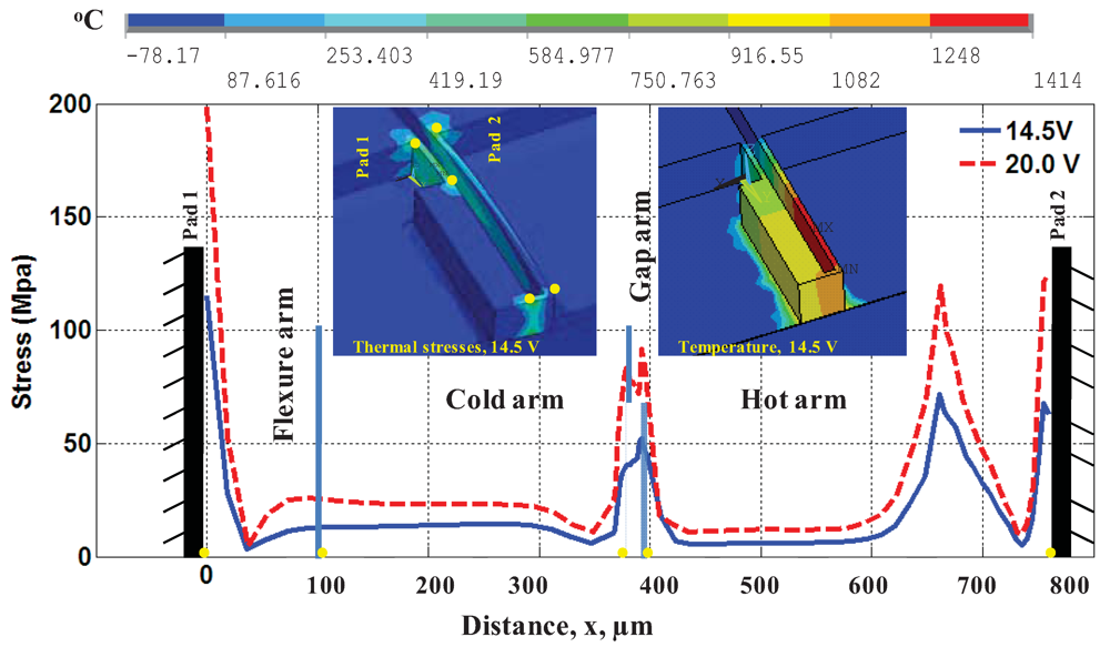
In
Figure 8, the Von-Misses thermal stress and temperature distribution were simulated along the microstructures for inputs 14.5 V and 20 V. The silicon compressive strength is 120 MPa [
13]. The dimensions and properties for the FEM simulation are from
Figure 5, and
Table 1, respectively. The FEM analysis suggests that the thermal stress at 14.5 V may not cause failure at root of flexure arm. However, the melting occurred in the “hot arm” microbeam with a peak temperature of 1,414 °C, as shown
Figure 9(b). On the other hand, the folded beam in
Figure 9(c) has two distinct failures caused by input of 20 V: the first is melting failure due to maximum temperature at hot arm, and the second is thermo structural failures due to stresses around the roots of flexure and hot arms.
Figure 8.
Thermal stress and temperature distribution of folded beam actuator.
Figure 8.
Thermal stress and temperature distribution of folded beam actuator.
Figure 9.
Thermal failure experiments: (a) SOI folded beam; (b) failure on hot arm due to melting at (~14.4 V); (c) multi failures in hot and flexure arms due to (~20 V).
Figure 9.
Thermal failure experiments: (a) SOI folded beam; (b) failure on hot arm due to melting at (~14.4 V); (c) multi failures in hot and flexure arms due to (~20 V).


 . Second, E-T actuators is operating in vacuum with no heat losses where βi =
  ρξ and T∞i =T − 1/ξ.


 in folded beam from analytical models.