Article

The Concept of Demonstrating Non-Existent Architecture Using Light Projection

1
Department of Architectural Design and Engineering Graphics, Faculty of Civil and Environmental Engineering and Architecture, Rzeszow University of Technology, 35-959 Rzeszów, Poland
2
Department of Power Electronics and Power Engineering, The Faculty of Electrical and Computer Engineering, Rzeszow University of Technology, 35-959 Rzeszów, Poland
*
Author to whom correspondence should be addressed.
Arts 2025, 14(2), 35; https://doi.org/10.3390/arts14020035
Submission received: 11 October 2024 / Revised: 3 March 2025 / Accepted: 22 March 2025 / Published: 25 March 2025
(This article belongs to the Special Issue Aesthetics in Contemporary Cities)

Abstract

:
This article covers the subject of illusory exposure of non-existent architectural objects in their original location. The authors believe that this specific conservation method is a way to disseminate knowledge about the past architectural landscape and thus to increase the identity of cities and their inhabitants. The concept refers to augmented reality, but the authors use only analog optical means to visualize the virtual component. The visualization consists of projecting the object onto the walls of buildings and the ground. In order to preserve their intact condition, light projection is used. The image creates the illusion of three-dimensionality if it is perceived from the center of the projection. After a preliminary analysis of the available means of light expression, this article presents the results of this research. In the first stage, a simple geometric model was visualized using various techniques in order to evaluate them and select the optimal one. In the second stage, a virtual visualization of a specific architectural object was created. Its form and location were established based on the analysis of historical iconographic material and reports from archaeological works. The influence of local conditions on the practical possibilities of light projection was taken into account.

1. Introduction

1.1. Illusory Reconstruction In Situ as Information About Unpreserved Architectural Objects

Over the past few decades, views and practices regarding the protection of cultural heritage have undergone significant transformations. The factors responsible for these changes are the spread of the idea of sustainable development and technological progress, especially in the field of digital technologies. The impact of the sustainable development concept is expressed in two dimensions: ecological and social. The first is manifested by a broader consent to change the function of historic buildings and use them for contemporary purposes (Li and Tang 2024), as an expression of concern for limiting the expenditure of energy to replace an existing material substance with a new one. The social aspect concerns shaping social balance by disseminating knowledge about the past of places (Liang et al. 2023). In order to achieve this goal, in addition to protecting the preserved heritage, access to knowledge about those artifacts that have been destroyed is important. Modern technologies help to a large extent, e.g., by allowing for detecting underground locations and shapes, building virtual models, etc. The development of laser scanning allows for recording precise spatial data about buildings in case of their possible destruction in the future (Koszewski et al. 2021). The semantic aspect of heritage is becoming more important nowadays than its material form (Taher Tolou Del et al. 2020). The legibility of meanings in the city space strengthens the urban identity, which is important for shaping the self-identities of residents and their well-being (Mansour et al. 2023).
The most common forms of remembrance in situ of lost architectural heritage are a permanent ruin, an exposed archaeological site and a trace marked in the pavement by a different kind of material. These forms convey information about the location of the building and the dimensions of its plan, but they do not inform about the vertical configuration of the architectural form. In some cases, a mock-up is placed next to it, but it does not provide a representation of the model in its natural scale and against the background of elements that create the contemporary environment. There are several known implementations: in Philadelphia (Artemyeva and Balzannikova 2020), Berlin (Ward 2016) and Siponto (Del Sole 2021), spatial structures were used, precisely marking the volume of the lost object in space, allowing one to see through them to what is beyond. This solution is difficult to apply if the space appropriate for a possible exhibition has been reshaped.
Nowadays, an attractive tool is augmented reality (AR), which allows for the simultaneous perception of real objects and virtual representations of objects that do not exist (Russo 2021). Interest in AR applications in the area of cultural heritage (CH) is growing rapidly. This is noted both in the increase in the number of publications on this topic (Zhang et al. 2024) and in practical implementations (Ramtohul and Khedo 2024). AR applications in the CH area can be classified as indoor and outdoor, based on fixed or mobile devices, and as presenting lost architectural objects or lost social life in a preserved architectural setting. In the vast majority of cases, AR is used in museums, archaeological open-air museums, etc., i.e., in spaces where the activity of people is focused on the reception of CH. The attractiveness and ambiguity of AR felt among people experiencing the same sensations at the same time facilitates interaction (Panhale et al. 2023). Not all these aspects are relevant to the topic of this article.
Taking technical aspects into account, individual solutions have different advantages and disadvantages. Mobile device applications can be based on the function of tracking images perceived by a moving user or tracking the path of his movement. In both cases, they show unreliability due to the insufficient computing power of the devices. Applications in which orientation in space is based on markers are more efficient. However, markers may not be aesthetically desirable and may not be visible in poor lighting or from a distance. Most often, AR is made available via applications for mobile devices equipped with a camera (Quattrini et al. 2016; Panou et al. 2018; Boboc et al. 2019). The image of the virtual object is superimposed on the image of the surroundings recorded by the camera, and both are displayed together on the device’s monitor. Even though the observer is present near the location of the visualized object, he does not perceive the surrounding space directly, but by the image filling a small part of the visual field. Users focus 70% of the time on the device screen instead of interacting with real objects (Ramtohul and Khedo 2024). The situation is different when using Hololens goggles. The image of the virtual object is displayed on the transparent display, while the surrounding reality is viewed with the unaided eye. The image of virtual objects is perceived better indoors than outdoors due to the relative stability of the lighting conditions. While augmented reality is not new, it has not yet become widespread in outdoor applications due to unresolved technical issues (Numan et al. 2023).
The authors focused on researching analog methods of illusory visualization using means that are present and clearly visible in public spaces. The transparent board with a drawing on it is the simplest and practically used means. It provides an observer occupying a specific position in space with the illusory perception of the authentic dimensions and location of an architectural object (Kohlsted 2020; Piekarski et al. 2021). The lack of interference in the developed space is an advantage of this solution. The invisibility of the image for people nearby, but not in front of the board, makes this method somewhat similar to the augmented reality received by a mobile device.
The authors’ intention was to find such a method of illusory reconstruction that would not introduce additional physical elements into the architectural space and would ensure the obvious visibility of the reconstruction. The creation of a drawing using light projection is a way to exclude any interference with the existing matter. The drawback is the limitation of the time of perception of the illusory image to night and evening. It provides the benefit of multiplying and complicating meanings in the same architectural space (Rewers 2005).

1.2. Light as a Means of Enriching Architectural Space

The most common form of using light to enrich architectural space is the illumination of its characteristic elements. Illumination is used to highlight buildings, bridges, fountains, monuments, gardens, etc., at night. Illumination can also achieve other purposes, including showing the appearance of the object alternative to that seen during the day, creating a romantic atmosphere and beautifying the night appearance of a city or street, as well as improving the safety of the object and its surroundings (Żagan 2003; Żagan and Krupiński 2016; Schielke 2019).
In recent years, the number of implementations of illumination projects has been increasing. One reason is the progress in light sources. The development of semiconductor technology and the use of LED sources have provided opportunities that were not available when discharge light sources were used (Baran et al. 2019). The high energy efficiency of LED sources resulted in a reduction in the power necessary to illuminate a specific object. If the illumination of a large architectural object previously required electrical power of 100–200 kW, now, a power of 20–30 kW is sufficient (Żagan and Krupiński 2016). Other advantages of LED sources include easy control of power, luminous flux level and light color, as well as small luminaire dimensions and precise luminous flux distribution (Lasance and Poppe 2014; Acuña et al. 2015; Różowicz et al. 2022). Another factor causing the increase in interest in illumination is the development of graphic computer applications that enable the creation of advanced and multivariant illuminations of architectural objects (Wachta et al. 2019; Krupiński 2021; Krupiński et al. 2021).
Among the methods of illuminating the facade of an architectural building, there are two main illumination methods: flood and spot. Flood lighting involves placing floodlights at a considerable distance from the illuminated object so that the light “floods” a significant area of the facade surface. This method is used to illuminate small objects, e.g., monuments, where the installation of a small number of floodlights makes it possible to illuminate the entire structure of the object. The flood method is justified when the illuminated object is characterized by one direction of observation. If there are several equivalent directions of observation, point illumination is preferred.
The spot method is characterized by the installation of floodlights in close proximity to the illuminated object. The task of each of them is to illuminate a selected zone or detail of the object. This method ensures an unchanging perception of the illuminated object, regardless of the direction of observation. Highlighting selected details, e.g., bas-reliefs, available in the spot method, encourages one to observe the architectural object from a close distance. The spot method allows for highlighting attractive details and hiding those that are less visually interesting. It is more difficult from a technical point of view due to the need to direct a significant number of floodlights. In the case of a large number of floodlights, there is a risk of losing the image integrity of the object. This happens when the light spots formed by individual floodlights do not merge into a whole or the vertical or horizontal division or symmetry of the object is disturbed. For this reason, it is important to use advanced simulation tools to visually evaluate the concept and confirm the consistency of the image at the design stage (Żagan and Krupiński 2016). In certain conditions, obtaining a satisfactory visual effect requires the use of a mixed method, i.e., lighting certain zones in a spot manner and other parts of the object in a flood manner. Figure 1 shows examples of architectural objects whose night lighting was implemented using the above-mentioned illumination methods: flood and spot (Bojda et al. 2015).
The development of semiconductor light sources and the use of LED fixtures for the decorative illumination of objects have made it possible to create dynamic lighting. LED floodlights in RGB technology enable precise control of the color and level of light flux. Advanced control systems and dedicated applications allow for the creation of visual sequences within the illuminated object. The dynamic method of illumination provides the possibility of changing the perception of the object, e.g., by changing its color according to the seasons and distinguishing it from the background of neighboring illuminated objects (Figure 2a).
Another popular technology that is mapping. It allows for changes in the appearance of the object without introducing architectural changes. In mapping technology, the projector displays a static image or animation, e.g., on the wall of a building. Possible special effects include changing color, moving architectural elements or changing shadows. They evoke a subjective feeling of illusion in the recipient, creating a new way of perceiving the object on which the image is displayed. The mapping demonstration is preceded by the design stage, in which a model of the object is created using advanced graphic tools, and then the visual part displayed on the object is designed. Unlike the illumination of facilities for which the lighting installation is permanent, mapping is used mainly for special events and cultural events (Figure 2b).

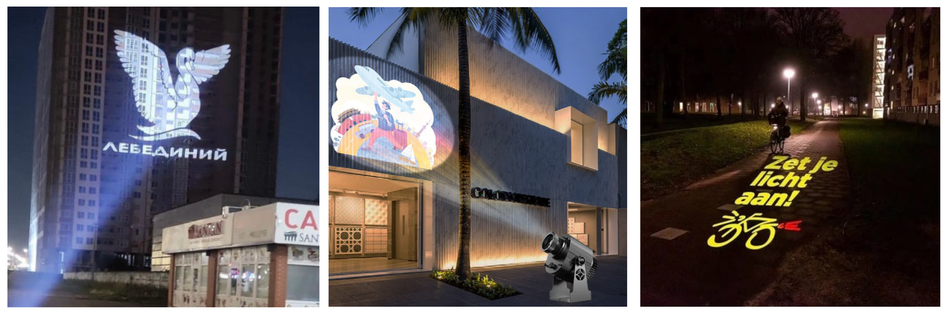
1.3. The Use of Light for Illusory Reconstruction

The perception of visual effects by the observer of illumination lighting or mapping depends on his position, the nature of the illuminated surface and its reflectance. There are three fundamentally different cases of perceiving the final luminance L (1). In the first one (Figure 3a), the surface of a solid body is illuminated, and the light reflectance coefficient ρ remains constant. In the second case (Figure 3b), a surface with a variable reflectance, e.g., water steam or smoke, is used to implement lighting or a light show. In the last case (Figure 3c), the observer looks directly at the light source of a given luminance L. The luminance L on the illuminated surface perceived by the observer’s eye is given by the following formula, where L is the luminance at the point of the illuminated surface, E is the illuminance at the point of the illuminated surface and ρ is the light reflectance coefficient of the illuminated surface.
L = E · ρ π
The lighting methods described in Section 1.2 included radiating a light flux or displaying an animation on a surface with a constant reflectance ρ (Figure 3a), e.g., the wall of a building. Another solution is the projection of light images using an image fluid carrier (Figure 3b) in the form of steam, smoke (Figure 4a) or a curtain of water (Figure 4b). In this case, it becomes difficult to ensure a constant value of the reflection coefficient ρ of the projection surface, which is why the image displayed on a liquid medium usually becomes distorted. Despite their great attractiveness, projections on a liquid medium, unlike projections on solid surfaces, are carried out only during special events or at selected time intervals. This is due to the difficulty of supporting an artificial projection surface, which generates a high cost of producing the show. On the other hand, due to the fact that the projections are addressed to an audience that usually gathers specifically to watch the show, dynamic projections have gained an advantage, as they make a greater impression than static illuminations.
An example of lighting in which the observer focuses directly on the light source (Figure 3c) is a media facade. It consists of a stainless steel mesh with connected busbars containing rows of diodes, usually RGB. The media mesh can be used for decorative lighting of an object, but using control systems and a high density of diodes, it is possible to display dynamic light images. The quality of their perception depends on the pixel resolution, the distance of the observer from the facade and the contrast between the luminance of the light source and the background. Another type of dynamic lighting, in which the observer focuses his eyes directly on the light source, is the lighting of the glass facade surface using controllable linear LED luminaires in RGB technology. They also enable obtaining controlled multi-colored light.
Solutions in which the observer looks directly at light sources may lead to glare. The cause of this phenomenon is usually too high a level of luminance of light sources and their incorrect control. Glare may be dangerous for drivers when illuminated objects are located near main roads and city arteries. The risk of glare does not exist in situations where the image is created as a result of reflection from an artificially created projection surface (Figure 3b).
Another less frequently used lighting technique is the use of a system of optical fibers with side glowing. In this solution, the light beam introduced into the flexible tube “moves” inside the transmission corridor created in the tube, and part of it is radiated outwards through the side walls of the optical fiber. Most often, these types of solutions work well as contour forms. In Warsaw, optical fibers with side glowing were used in an artistic installation that reconstructs a footbridge connecting during the German occupation of two parts of the Jewish ghetto separated by a street, exactly in the place of its original location (Markowski 2022). Yet another method of reminiscing non-existent buildings with light is to use only beams of light. There is a well-known project to commemorate the World Trade Center skyscrapers in New York using light rays directed vertically upwards, which mark, in space, the volume of buildings destroyed in 2001 (Artemyeva and Balzannikova 2020).

2. Plan and Characteristics of This Research

The aim of this study is to find the optimal method of presenting non-existent architecture in a public space where all everyday functions are performed. The aim is to present it in a way that will be naturally perceptual for every user of the space. Digital AR does not meet this condition because it requires the use of an additional means, in practice, most often a smartphone. Even though it is now an inseparable element of handheld equipment, using a smartphone to receive AR requires awareness of this fact and activity that goes beyond the routine behavior of a passer-by. The limited screen size excludes the co-reception of AR and the entire spectrum of stimuli coming from the environment.
Due to all these problems, the authors decided that the optimal method of visualizing the reconstructed architectural object would use light and display a drawing constituting its projection on the physical components of a public space, such as building walls, street pavement, etc. Of course, this method is appropriate mainly for cases when the building illusory reconstructed was located in a space that is currently empty and surrounded by other buildings. This type of projection is called anamorphosis and is known from artistic installations (Empler 2017; Araújo 2020) and applications in theatre scenography (Čučaković and Paunović 2016). Anamorphosis, as a method of projecting onto multiple non-coplanar viewports, provides perception that ensures the illusion of viewing a three-dimensional object from only one specific point, but observers in other locations are intrigued by its presence. Usually, the position of this point is considered as invariant in space. The concept of the light projection of an image from a head-mounted projector has been also considered (Yoshida et al. 2021). In this case, the displayed image is processed in real time to adapt it to the current position in space occupied by the observer. The term anamorphosis is also used to describe another method of illusory visualization of objects, which involves reflecting an appropriately deformed image drawn in the ground in a mirror (Hansford and Collins 2007). Even more broadly, the term refers to any flat drawings that create a three-dimensional impression when viewed only from a precisely defined point (di Paola et al. 2015). This type of anamorphosis is one of the trends in street art (Bartolomei et al. 2020).
The idea of anamorphosis, understood in the first sense described above, is based on the use of perspective projection (Pottmann et al. 2007). The only difference from the classically understood perspective is the use of many differently oriented surfaces on physical objects as viewports instead of one vertical plane. In the experiment conducted, views were constructed using AutoCAD 2024. In the three-dimensional virtual space of the program, the surrounding objects, the reconstructed object and the point that was the center of projection, corresponding to the position of the observer’s eye, were defined. From the center of the projection, straight lines were drawn through the characteristic points of the projected object. Then, the points of intersection with the surfaces of the objects constituting the surroundings were found (Figure 5a). In practice, due to the program’s inability to find common parts of lines and surfaces, both were replaced by solids with imperceptibly small cross-sectional dimensions.
A similar but slightly more complicated procedure was used for experiments involving the creation of a view using light projection. In this case, the observer’s eye and the light source cannot be at the same point. First, in the manner described above, the so-called primary view was established. In the next stage, a secondary view was constructed as a central projection of the primary view on a plane perpendicular to the direction of the light beam projected by the reflector (Figure 5b). The secondary view was constructed in AutoCAD according to the procedure described above for the primary view.
The authors decided to carry out the variant model tests on a simple geometric shape in order to select a light projection method that would be most effective in public spaces. They intended that after collecting experience, a virtual simulation of the reconstruction of a specific architectural object in an actually existing public space would be carried out. For this purpose, the so-called Masonry Gate in Rzeszów was chosen. Because the facility was demolished at a time before the invention of photography, no accurate images of it exist. The precise location and architectural form were determined based on the analysis of reports from historical and archaeological research and available iconographic material. The simulation of the Masonry Gate illusive reconstruction will allow for verification of theoretical analyses and experiments and will serve to interest the owners of this space in the effect, as well as to convince them to agree to the actual implementation.
The authors chose a cube as the object visualized during the preliminary empirical research. The use of an object that is easy to imagine and identical in form was considered a factor facilitating the comparison of the quality of individual types of visualization. Although the goal is an illusory reconstruction in public space, preliminary research was carried out indoors due to the possibility of eliminating the presence and interest of outsiders.
The authors decided that this research would cover the following types of visualization:
  • A drawing mapped on surfaces constituting the viewports of the projection;
  • A drawing displayed on these surfaces.
It was agreed that the order of research would be as presented above, which would enable corrections to be made resulting from the conclusions drawn successively. The position of the cube relative to the ground and wall was subject to additional variations. In addition to the figure located exactly on the ground and external to the wall, cubes partially penetrating the walls and the ground were analyzed.
Light projection can be achieved in two ways: using a projector that displays an image from a computer and using a reflector that illuminates a physical object and displays its shadow on the background. In the first method, in addition to displaying the wireframe model, displaying a model with completed walls is also possible. In the second method, only the wireframe model can be displayed, but it can be viewed as a set of dark lines, constituting the shadows of the openwork projection model, or a set of light lines, constituting streaks of light penetrating through slots cut in the full plate. Due to the necessary consistency of the material outside and inside the projection outline, the displayed lines cannot be continuous; they must be dashed.

3. Description of This Research

3.1. Experimental Research

A cube with an edge length of 1 m was subjected to an illusory representation. The projections of the cube were marked on the floor and wall of the room using 38 mm wide adhesive tape. It was decided to mark all the edges of the cube, i.e., to present its wireframe model. It was felt that not marking the invisible edges would make the experiment more difficult to understand, especially for less prepared recipients. The observer’s position was designated at a distance of 6 m from the wall, being a plane of projection on the line tilted from it by a 40° angle.
First, a cube located entirely in front of the wall of the room, one face of which is contained in a plane parallel to this wall (Figure 6a,b), was visualized. The second test concerned a cube rotated around a vertical axis and partially penetrating the wall of the room (Figure 6c,d). These changes were not found to impair perception. The intuitive restitution of the cube turned out to be obvious. The authors decided that it was not necessary to mark the position of the observer’s eye in space, which they initially intended to mark. A moving observer easily encounters a place from which he perceives the drawing as an image of a cube. The plinth turned out to be a minor problem. Due to its small thickness (10 mm), the plinth was not included in the construction of the drawing. This caused considerable discomfort in perceiving a cube. Finally, a correction of the projection was introduced, which took into account the presence of the plinth.
Two light projection tests were carried out using a projector. In the first one, the room was not darkened, and the image was projected onto the floor and wall. Based on the experience gained during the experiment described above, a place was selected where the wall was without a plinth. Each time, the visualized cube was embedded in the ground, and in the case of the visualization of a surface model, it was also embedded in the wall. In the wireframe image, the portions of the edge above the floor were shown with a thicker line than that used to represent the fragment embedded in the floor (Figure 7a,b). The surface model was visualized in several ways, varying the colors and intensity of lines (Figure 7d–f). The dimensions of the cube and the location of the observer were scaled in a 1:2 ratio, relative to the dimensions of the previous experiment. The projector was located 4.5 m from the wall, on the line located perpendicular to it.
The second test was performed in a darkened room. Both background surfaces—horizontal and vertical—were covered with the same material in the form of cardboard sheets. In the wireframe model, the lines projected on the horizontal plane were thicker and less sharp than the lines projected on the vertical plane (Figure 8a). The surface models (Figure 8b–e) provided a deeper impression of the illusion compared to the models displayed in a non-darkened room (Figure 7d–f). In the authors’ opinion, additional edge highlighting (Figure 8b) enhances the image quality.
The third test involved the use of a reflector to illuminate a physical object casting a shadow. The experiment was conducted in the same setting as the trial described above. In the positive image, due to the need to attach the projected object (Figure 9a), in addition to the cube itself, the mounting element was also displayed (Figure 9b). The negative image (Figure 9d) looked like streaks of light against a dark background that was the shadow of the tile (Figure 9c). In both cases, an analogous effect was observed: the lines displayed on the horizontal plane were thicker and less sharp compared to the lines displayed on the vertical plane. The reason is the different angle of incidence of light rays on each projection plane. Improving this state requires varying the thickness of individual parts of the projected physical object, or, in the method using a projector, the thickness of individual lines in the projected image.

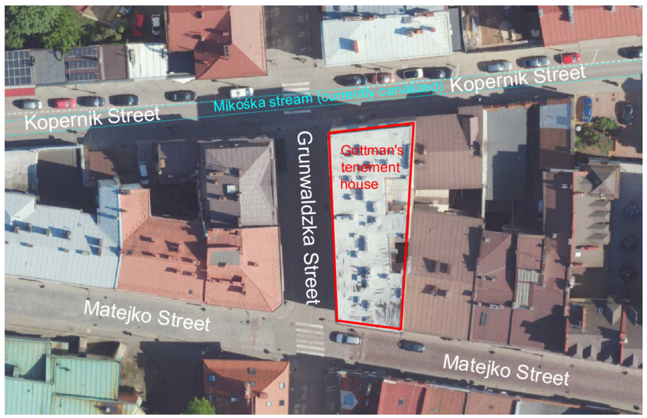
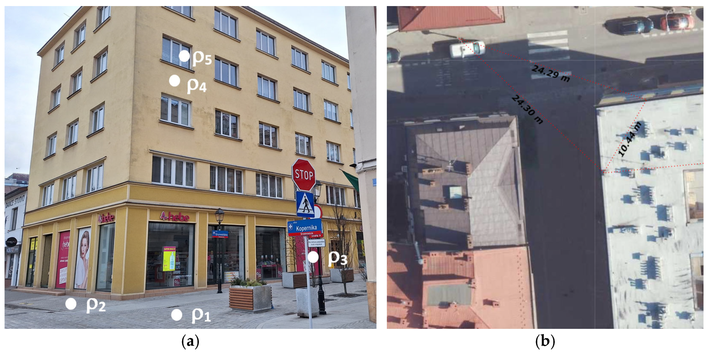
3.2. Simulation of the Light Projection in an Authentic Public Space—“The Masonry Gate” in Rzeszów

3.2.1. The History of the Building and the Place

The object selected for the illusory reconstruction is the Masonry Gate in Rzeszów, also known as the Sandomierska Gate or the Red Gate. General mentions confirming its existence are in archival documents, but there are no factographic or iconographic materials that would provide precise information about its location and spatial form. The gate was probably built at the end of the 16th century or the beginning of the 17th century. It arouses emotions to this day because, according to archival documents, it was a large masonry structure, making it different from the rest of Rzeszów’s fortifications, which were rather earthen and wooden. Several 20th-century researchers addressed the topic of the Masonry Gate in their studies, but suggestions as to its location are not clear. Since the oldest of these studies (Kotula 1958) contains contradictory information, the authors of the newer investigations tend to locate the gate at the intersection of contemporary Grunwaldzka Street and Matejko Street (Bogdanowski 1974) or Grunwaldzka Street and Kopernik Street (Wzorek 1986; Borowiejska-Birkenmajerowa 1994). The latter version is more likely to be attributed to the Mikośka stream, which still flows hidden under Kopernik Street. The waters of it, according to various sources, were, in earlier times, a natural defensive element of Rzeszów from the north.
Nowadays, in the vicinity of the alleged location of the Masonry Gate, there are no clear traces of the urban layout from the times of its existence. The buildings on both sides of Grunwaldzka Street and Kopernik Street date back to the 19th and 20th centuries. One- and two-story buildings dominate. The exception is a four-story residential building with commercial premises on the ground floor, built in 1937, and called Gottman’s tenement house. It constitutes the eastern frontage of Grunwaldzka Street on the entire section between Kopernik Street and Matejko Street. Grunwaldzka Street is closed to car traffic, and on Kopernik Street, one-way traffic is allowed from west to east (Figure 10). Recently, a comprehensive modernization of Grunwaldzka Street was carried out, including the replacement of the pavement and street furniture as well as the implementation of plantings.
The basis for the reconstruction of the location of the Masonry Gate was the results of archaeological research carried out twice over the last 30 years. The conclusions from the research conducted in 1998 (Lubelczyk 1998) are not identical to the conclusions formulated in the research report from 2021 (Drewniak et al. 2021). According to the authors, the latest results are reliable because the archaeological site covered a large area and the conclusions drawn form a logical whole. As for the wall relics discovered during the research, it is difficult to say unequivocally that they are the remains of a gate. Newer cultural layers, including the presence of numerous technical installations, disturb a clear image. The most convincing is the discovery of relics of wooden beams and stone cubes on both sides of the supposed location of the gate. They mark the course of the road and, therefore, the location of the gate through which the road must have passed. These premises show that the axis of the then road deviated in relation to the axis of the current Grunwaldzka Street and moved towards the east (Figure 11a). This theory is confirmed by comments from the period of construction of Gottman’s tenement house about the discovery of old walls in foundation excavations (Kotula 1958). Also, the image of the city from 1762 (Wiedemann 1762) points to the oblique direction of the road in relation to the current axis of Grunwaldzka Street (Figure 11b). Taking into account the sizes of better-preserved relics of city gates, from a similar period and located nearby (e.g., the Krakow Gate in Jarosław), a hypothesis was put forward that the dimensions of the gate were approximately 10 × 10 m in the plan, and, as discovered during the archaeological works, fragments of the walls were considered to be its north-west corner. It was also hypothesized that the road pavement at that time was approximately 2 m below the modern one.
The perspective view of Rzeszów from 1762 became the basis for the reconstruction of the architectural form of the gate. At the time of its preparation, the gate no longer fulfilled its original function. Its current form was probably the result of the modernization. However, the drawing, commonly known as the Wiedemann plan, plays an important role in shaping the identity of Rzeszów and its inhabitants. All the representative buildings presented there have survived to the present day, so the credibility of the Wiedemann plan can be easily assessed. Despite the proven significant inaccuracies in Wiedemann’s presentation of the urban layout of Rzeszów (Piekarski 2023), the assessment of the accuracy of the reproduction of architectural objects is positive.

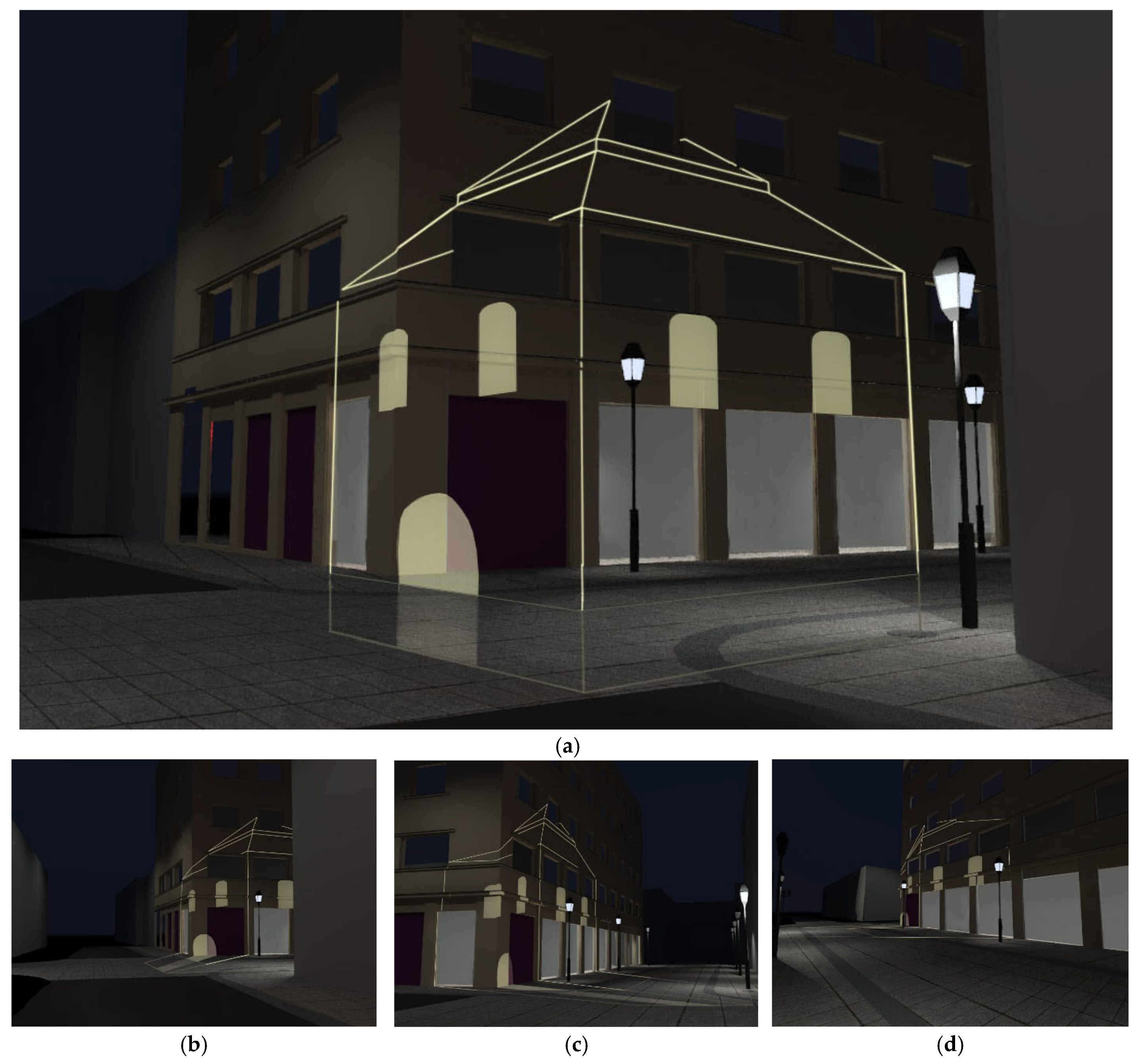
3.2.2. Light Projection Constraints and Design

The authors’ intention was to provide an illusory reconstruction of the Masonry Gate both for the awareness of its past existence and to indicate its exact location based on the conclusions drawn in Section 3.2.1. Due to the probable penetration of the gate into the solid of Gottman’s tenement house and into the ground, the walls of the building and the street surface must be used as the background of the light projection. Gottman’s house creates relatively good conditions as a projection screen. Its modernist form contains a minimum number of details, and the building itself is high enough to take the projection of the gate onto its walls.
Individual surfaces considered as the projection background are characterized by different reflection features—ρ1, ρ2, ρ3, ρ4 and ρ5 (Figure 12a). This applies to quantitative properties—the values of light reflection coefficients from the surface and qualitative ones—identified by the degree of dispersion of the light beam reflected from the material. Quantitative features are related to different color temperatures of materials, such as facade plaster, window panes, advertisements placed in the recesses of exhibition windows, the surface of the sidewalk surrounding the facility and street sections. The second group of qualitative features is related to directional or close-to-directional reflections—window panes, directionally diffuse and Lambert reflections—plasters, sidewalks and road surfaces. The readability of the image displayed on parts of the sidewalk, road and facade will directly depend on the contrast created between the background luminance and the displayed sign. In this sense, the reference (base) background luminance will be the zone of the object with the lowest color temperature (the darkest color of the reflecting surface). Unfortunately, the reconstruction of the street was carried out according to a project developed several years earlier, which did not include the illusory reconstruction of the Masonry Gate. The surfaces constituting the background of the projection are partially obscured by a road sign, a street lamp, one tree planted in the ground and movable plant pots. With the goodwill of the city authorities, all these elements can be easily moved in order to create the right conditions for displaying the image of the Masonry Gate.
Bearing in mind the expectation of a clear display of the sign displayed on the facade, apartment windows and large shop windows should, if possible, be excluded from the planned lighting. The choice of where to place the projector should also depend on this condition. Avoiding directing the light beam towards windows is an additional measure to prevent light immission. Shop windows can be covered with non-transparent advertisements.
A separate issue that needs to be considered is the impact of street lighting on the facades of the facility, the sidewalk surrounding the building and the road sections adjacent to the facility. Modern street lighting affects the surroundings in the lower half-space relative to the mounting height of the luminaire above the street. It is likely that the part of the facade covering the upper floors will not have any light interaction with street lighting. However, taking into account the possibility of the zone lighting of part of the facade covering the ground floor, as well as the sidewalk and street by lanterns mounted close to the facade, a contoured light exposure should be planned. The color temperature of the outline should create a clear contrast with the color temperature of the light sources of street lighting, which is usually in the range of 3000–4000 K. Additionally, it is necessary to consider the possibility of covering part of the lampshade of the street luminaire from the facade side or reducing the luminous flux of a given lantern for the duration of exposure.
Apart from the impact of street lighting, a factor that negatively affects the quality of the projection is the creation of dynamic shadows on the facade from pedestrians moving on the sidewalk. The scale of this phenomenon can be reduced by planning to install the projector at a higher height, with the light beam directed downwards. As for car drivers, favorable circumstances include the lack of car traffic on Grunwaldzka Street and one-way traffic on Kopernik Street, consistent with the expected direction of the light beam. This means that drivers could only be exposed to the light source through their rear-view mirrors. The extent of glare to passers-by and drivers can be reduced by designing the lighting exposure in a contour form rather than a surface form.
A clear contour exposure can be achieved by using LED technology, exploiting dedicated metal matrices with slots allowing part of the light flux to pass towards the illuminated object (Figure 13). Despite the low weight of this type of equipment, ranging from 1.5 to 2 kg, the LED projector is able to produce an image up to 70 m in diameter, located 70 m from the projector. In the case under consideration, the distance from the projector to the facade will be approximately 25 m, and the light spot will have a diameter of approximately 11 m (Figure 12b). The long service life of LED sources and their ability to maintain the light flux over time is an additional advantage in favor of their use. LED projectors available on the lighting market with a power of approximately 70–100 W have a small body size and high IP67 tightness (Figure 14a,b). This equipment is characterized by a long projection range of a readable image with a color temperature of 6000–8000 K, even on a dark facade.
The idea of light exposure provides for the possibility of observing an undistorted contour outline only from one place. This specificity creates a challenge for potential observers in finding the place for proper observation without deforming the contour of the historical object. Care should be taken to ensure that, in addition to guaranteeing the safe installation and power supply of the projector, there is a sufficiently large zone in the sidewalk area where pedestrians can stop so as to observe the projection of the contour of the historical structure on the building’s facade without limiting the flow of traffic of vehicles and other pedestrians.
The creation of a light projection project requires a thorough inventory of the surfaces on which the image will be displayed. If these surfaces are building walls, they are usually not completely flat but full of irregularities in the form of recesses of window and door openings, cornices, pilasters, bay windows, etc. Each inequality affects the shape of the secondary projection (Figure 5b). An inventory of the walls of Gottman’s tenement house, on which the image of the Masonry Gate will be displayed, was made manually, using simple tools such as a laser rangefinder and a measuring tape. It is possible to use 3D scanning for this purpose. This approach would be preferred especially in the case of greater roughness of the facade and the need to take measurements at a higher height. A separate issue is the need to have a place to locate the scanner from which the laser rays would be able to reach all corners of the facade.

4. Results

Based on the inventory of the Gottman building, the virtual three-dimensional model of it was built, and due to the partial marketing nature of the simulation, simplified models of the surrounding buildings were also built. The model of the Masonry Gate was constructed based on the results of archaeological research (Figure 11a) and a drawing from Wiedemann’s plan (Figure 11b). The shape and location of the object are approximate, not only due to a degree of uncertainty in factographic sources but mainly to ensure that the light streaks are displayed as much as possible on the surface of the wall and the pavement and as little as possible on the window panes. For this reason, it was decided to project the wireframe model and refrain from displaying the fragments of lines that would fall on the glass panes (Figure 15a). The sizes and locations of the windows in the gate building were selected so that their projections were within the strip of the facade between the ground-floor shopwindows and the first-floor windows. The gate was placed below the modern street level, which reflects the historical truth and helps to reduce the height of the image displayed on the wall of the building and limit possible nuisance for its inhabitants. The part of the gate embedded in the terrain was distinguished from the part raised above its surface by lines of less intensity, and the product of the pavement with the external surfaces of the gate walls was additionally marked. Due to the fact that the projection would be made on the walls belonging to the frontages of two perpendicular streets, the deformed image of the gate would have the potential to intrigue passers-by coming from different directions (Figure 15b–d).
The virtual light projection scene was built in AutoCAD. After modeling the objects described above, the outline of the gate was projected onto the building walls and the pavement in accordance with the idea presented in Figure 5a. A point at a height of 1.60 m above the northern sidewalk of Kopernik Street was chosen as the center of the projection. Then, a secondary central projection (Figure 5b) was made, taking the position of the reflector as the center of the projection, located 7 m above the sidewalk surface, in the place where the street lamp is located (Figure 12b). The visual effect was achieved by introducing light from a virtual spotlight and placing in front of it a model of a tile with a slot in the shape of a secondary projection (Figure 5b) of the Masonry Gate.
The visibility of the contour presented on the building facade depends on a number of factors (Barfuss et al. 2024). The most important of them are observation distance, detail size, contrast and lighting. For the adopted observation location, the distance from the facade is 24.3 m. The width of the contour line displayed on the facade was assumed to be 5 cm for this distance. According to the principles of visual perception, for good visibility of this line, the lighting intensity should be no less than 120 lx. If we assume an average light reflection coefficient from the facade of 0.5, then according to Lambert’s law, the luminance of the displayed contour line will have a value of 19 cd/m2. Illumination of the facade by lanterns allows for an average luminance on the facade of 6 cd/m2. Therefore, the contrast between the luminance of the contour line and the background of the facade is 3.16. This is a sufficient value to see the contour lines displayed on the facade. Additionally, the contrast is significantly enhanced by the difference in the color temperature of the elevation and the contour line. The adopted small distance of the observation point from the elevation practically completely eliminates the risk of deterioration of the contour visibility caused by haze. The projector proposed for use successfully meets the minimum requirements for the visibility of the line contour displayed on the elevation.

5. Discussion

Highlighting interesting details, architectural objects or places of special historical value requires combining many disciplines and technical solutions, including architecture, lighting technologies and virtual reality, as well as taking into account the protection and conservation of monuments. The development of lighting technologies, especially color LED sources, enables the night-time highlighting of an object through the use of static or dynamic illumination. Virtual reality technology, through the combination of modern multimedia solutions, as well as the observer’s imagination, enables the reconstruction and imaging of objects, such as historical places that existed many centuries ago. Despite many advantages, the above-mentioned technologies are often limited by significant implementation costs, as well as conservation restrictions related to the location and arrangement of, for example, large-size lighting luminaires.
The method presented in this paper is a modern method of visualizing the outline of non-existent historic buildings and, according to the authors, may be an interesting complement to contemporary illumination techniques. The limitations of the possibility of the free application of this technique in practice mainly concern the projection features of a given real object. These are primarily the number and size of windows, the size of the object, enabling the presentation of the entire outline of the historical object, limitations resulting from the risk of light immission to the interiors of inhabited rooms and limitations of the location of the projector and the availability of the observation zone of the projection effect. Without a doubt, they constitute a set of limitations of a smaller or larger rank; nevertheless, the presented example illustrates the effective application of the proposed projection solution.
The proposed projection technique will inspire observers to search for a zone in the vicinity of the projection elevation in which the presented outline will be possible to observe without distortions. According to the authors, this is an effective tool for stimulating the imagination of passers-by, activating their desire to find the most advantageous place to observe the implemented outline projection.

6. Conclusions

The results of practical experiments and computer simulation motivate the authors to intensify their efforts to convince the Rzeszów municipal authorities to implement the light projection of the Masonry Gate. The important factor that favors this initiative is the relatively easy technical implementation of the projection. The costs of purchasing the projector and its installation, use and servicing are low. Mounting the projector on a street lamp is easy and convenient because the lamp is owned by the city, is powered by electricity and allows the projector to be mounted at a high height. An open question is the prospects for supplementing contour projection with animation. Including this element can certainly enhance the attractiveness of the presentation. According to the authors, the animation should take the form of a several-minute sequence, only periodically supplementing the static presentation. These issues may become the subject of further work by the author’s team after the implementation of the static presentation.
In the future, the authors intend to extend their research to the analysis of other methods of the analog presentation of unpreserved architectural heritage in situ. In the field of light projection, experiments for displaying images on wire meshes are planned. This may help, to some extent, where there is a lack of physical surfaces that could constitute projection planes. The authors also plan to research stationary AR devices in which the image of the virtual environment is superimposed on the image of the real environment using only optical devices, excluding electronics and digital technologies. The variety of methods for visualizing non-existent heritage is desirable due to the diversity of spatial situations in individual locations. This would also have a positive impact on the attractiveness of places and the interest of users of public spaces.

Author Contributions

Conceptualization, M.P.; methodology, M.P., K.B. and E.K.; validation, M.P. and E.K.; formal analysis, E.K. and H.W.; investigation, H.W.; data curation, E.K.; writing—original draft preparation, M.P., K.B. and H.W.; writing—review and editing, M.P.; visualization, E.K.; supervision, M.P. All authors have read and agreed to the published version of the manuscript.

Funding

This research received no external funding.

Data Availability Statement

No new data were created or analyzed in this study. Data sharing is not applicable to this article.

Acknowledgments

The authors would like to thank Paweł Kocańda for shedding light on the state of the archaeological research in the considered area and indicating sources describing the results of this research. We would also like to express our thanks for the kindness shown to us by Grzegorz Dąbrowski, representing the owners of the building on which the light projection would be performed. We would like to express our special thanks to Edyta Dawidziak—Municipal Conservator of Monuments in Rzeszów—for organizing a public lecture during which we had the opportunity to present the concept of the light projection of the Masonry Gate to the Mayor of Rzeszów, experts and all interested persons.

Conflicts of Interest

The authors declare no conflicts of interest.

Notes

1
2
See note 1 above.
3

References

  1. Acuña, Paula C., S. Leyre, J. Audenaert, Y. Meuret, G. Deconinck, and P. Hanselaer. 2015. Impact of Geometrical and Optical Parameters on the Performance of a Cylindrical Remote Phosphor LED. IEEE Photonics Journal 7: 1601014. [Google Scholar] [CrossRef]
  2. Araújo, Antonio B. 2020. Anamorphosis Reformed: From Optical Illusions to Immersive Perspectives. In Handbook of the Mathematics of the Arts and Sciences. Edited by Bharath Sriraman. Cham: Springer, pp. 1–68. [Google Scholar] [CrossRef]
  3. Artemyeva, Tatyana, and Ekaterina Balzannikova. 2020. Application of metareconstruction method as a means of marking traces of lost historical buildings. In IOP Conference Series: Materials Science and Engineering. Bristol: IOP Publishing, vol. 775, p. 012005. [Google Scholar] [CrossRef]
  4. Baran, Krzysztof, Marcin Leśko, Henryk Wachta, and Antoni Różowicz. 2019. Thermal Modeling and Simulation of High Power LED Module. In Computational Technologies in Engineering (TKI’2018): Proceedings of the 15th Conference on Computational Technologies in Engineering, Jora Wielka, Poland, 16–19 October 2018. Melville: AIP Publishing, vol. 2078. [Google Scholar] [CrossRef]
  5. Barfuss, Meike, Alexander Rosemann, Dirk Seifert, and Werner Osterhaus. 2024. Lighting Technology. Fundamentals of Illuminating Engineering. Cham: Springer. [Google Scholar] [CrossRef]
  6. Bartolomei, Cristiana, Alfonso Ippolito, Cecilia Mazzoli, and Caterina Morganti. 2020. From anamorphosis to vision: “3D Sidewalk Chalk Art”. Disegnarecon 13. [Google Scholar] [CrossRef]
  7. Boboc, Răzvan Gabriel, Mihai Duguleană, Gheorghe-Daniel Voinea, Cristian-Cezar Postelnicu, Dorin-Mircea Popovici, and Marcello Carrozzino. 2019. Mobile Augmented Reality for Cultural Heritage: Following the Footsteps of Ovid among Different Locations in Europe. Sustainability 11: 1167. [Google Scholar] [CrossRef]
  8. Bogdanowski, Janusz. 1974. Okopy miejskie Rzeszowa i problemy ich konserwacji. In Rzeszowska Teka Konserwatorska. Edited by Barbara Tondos. Rzeszów: Muzeum Okręgowe/Biuro Dokumentacji Zabytków w Rzeszowie. [Google Scholar]
  9. Bojda, Paulina, Lúbomir Beňa, and Henryk Wachta. 2015. Create architectural illumination, taking into account the influence of road lighting. Advances in IT and Electrical Engineering 23: 13–22. [Google Scholar] [CrossRef]
  10. Borowiejska-Birkenmajerowa, Maria. 1994. Rozwój przestrzenny miasta za Mikołaja Spytka Ligęzy. In Dzieje Rzeszowa Tom I. Edited by Feliks Kiryk. Rzeszów: Krajowa Agencja Wydawnicza. [Google Scholar]
  11. Čučaković, Aleksandar, and Marijana Paunović. 2016. Perspective in Stage Design: An Application of Principles of Anamorphosis in Spatial Visualisation. Nexus Network Journal 18: 743–58. [Google Scholar] [CrossRef]
  12. Del Sole, Francesco. 2021. The Architectural Illusion of Edoardo Tresoldi: The Reconstruction of the Basilica of Siponto. Athens Journal of Architecture 7: 257–74. [Google Scholar] [CrossRef]
  13. di Paola, Francesco, Pietro Pedone, Laura Inzerillo, and Cettina Santagati. 2015. Anamorphic Projection: Analogical/Digital Algorithms. Nexus Network Journal 17: 253–85. [Google Scholar] [CrossRef]
  14. Drewniak, Konrad, Mirosław Mazurek, and Anna Okoniewska. 2021. Sprawozdanie z Badań Wykopaliskowych na Ulicy Grunwaldzkiej w Rzeszowie—Stanowisko Nr 17. Rzeszów: Fundacja Rzeszowskiego Ośrodka Archeologicznego. [Google Scholar]
  15. Empler, Tommaso. 2017. Anamorphosis and Contemporaneity. The Design Journal 20: 2858–72. [Google Scholar] [CrossRef]
  16. Hansford, Dianne, and Dan Collins. 2007. Anamorphic 3D Geometry. Computing 79: 211–23. [Google Scholar] [CrossRef]
  17. Kohlsted, Kurt. 2020. Remaking History: Transparent “Plaque” Helps People See into the Distant Past. Available online: https://99percentinvisible.org/article/remaking-history-transparent-plaque-helps-people-see-into-the-distant-past/ (accessed on 21 May 2024).
  18. Koszewski, Krzysztof, Jakub Franczuk, and Karol Argasiński. 2021. Architectural Heritage Virtual Models in Conservation Practice. Journal of Heritage Conservation 68S: 17–25. [Google Scholar] [CrossRef]
  19. Kotula, Franciszek. 1958. Obwarowanie Rzeszowa i rozwój przestrzenny miasta w XVII i XVIII wieku. In Pięć wieków miasta Rzeszowa XIV-XVIII. Edited by Franciszek Błoński. Warszawa: Państwowe Wydawnictwo Naukowe. [Google Scholar]
  20. Krupiński, Rafał. 2021. Simulation and Analysis of Floodlighting Based on 3D Computer Graphics. Energies 14: 1042. [Google Scholar] [CrossRef]
  21. Krupiński, Rafał, Henryk Wachta, Wojciech M. Stabryła, and Cedric Büchner. 2021. Selected Issues on Material Properties of Objects in Computer Simulations of Floodlighting. Energies 14: 5448. [Google Scholar] [CrossRef]
  22. Lasance, Clemens, and Andras Poppe, eds. 2014. Thermal Management for LED Applications. New York: Springer Science. [Google Scholar]
  23. Li, Lanxin, and Yue Tang. 2024. Towards the Contemporary Conservation of Cultural Heritages: An Overview of Their Conservation History. Heritage 7: 175–92. [Google Scholar] [CrossRef]
  24. Liang, Wen, Yahaya Ahmad, and Hazrina Haja Bava Mohidin. 2023. The development of the concept of architectural heritage conservation and its inspiration. Built Heritage 7: 21. [Google Scholar] [CrossRef]
  25. Lubelczyk, Antoni. 1998. Sprawozdanie z nadzoru archeologicznego prowadzonego nad pracami ziemnymi, związanymi z modernizacją sieci energetycznej w Rzeszowie w 1998 r. Manuscript in: District Museum in Rzeszów. [Google Scholar]
  26. Mansour, Hasan Mahmoud, Fernando Brandão Alves, and António Ricardo da Costa. 2023. A Comprehensive Methodological Approach for the Assessment of Urban Identity. Sustainability 15: 13350. [Google Scholar] [CrossRef]
  27. Markowski, Mateusz. 2022. Kładka nad ulicą Chłodną—Najważniejszy Symbol Warszawskiego Getta. Available online: https://www.whitemad.pl/kladka-nad-ulica-chlodna-najwazniejszy-symbol-warszawskiego-getta/ (accessed on 23 May 2024).
  28. Numan, Nels, Ziwen Lu, Benjamin Congdon, Daniele Giunchi, Alexandros Rotsidis, Andreas Lernis, Kyriakos Larmos, Tereza Kourra, Panayiotis Charalambous, Yiorgos Chrysanthou, and et al. 2023. Towards Outdoor Collaborative Mixed Reality: Lessons Learnt from a Prototype System. Paper presented at 2023 IEEE Conference on Virtual Reality and 3D User Interfaces Abstracts and Workshops (VRW), Shanghai, China, March 25–29; pp. 113–18. [Google Scholar] [CrossRef]
  29. Panhale, Tanvi, Derek Bryce, and Eleni Tsougkou. 2023. Augmented reality and experience co-creation in heritage settings. Journal of Marketing Management 39: 470–97. [Google Scholar] [CrossRef]
  30. Panou, Chris, Leonia Ragia, Despoina Dimelli, and Katerina Mania. 2018. An Architecture for Mobile Outdoors Augmented Reality for Cultural Heritage. International Journal of Geo-Information 7: 463. [Google Scholar] [CrossRef]
  31. Piekarski, Maciej. 2023. Topography of the 18th-century Rzeszów and its relics in the contemporary architectural and urban space of the city. Architectus 73: 17–29. [Google Scholar] [CrossRef]
  32. Piekarski, Maciej, Ewa Kulpińska, and Anna Prokop. 2021. Illusory Restitution of Not Preserved Architectural Objects—An Analysis of Methods and a Case Study. Space & Form 47: 83–104. [Google Scholar] [CrossRef]
  33. Pottmann, Helmut, Andreas Asperl, Michael Hofer, and Axel Kilian. 2007. Architectural Geometry. Exton: Bentley Institute Press. [Google Scholar]
  34. Quattrini, Ramona, Roberto Pierdicca, Emanuele Frontoni, and Roberta Barcaglioni. 2016. Virtual Reconstruction of Lost Architectures: From the TLS Survey to AR Visualization. ISPRS International Archives of the Photogrammetry. Remote Sensing and Spatial Information Sciences 41: 383–90. [Google Scholar] [CrossRef]
  35. Ramtohul, Arvind, and Kavi Kumar Khedo. 2024. Augmented reality systems in the cultural heritage domains: A systematic review. Digital Applications in Archeology and Cultural Heritage 32: e00317. [Google Scholar] [CrossRef]
  36. Rewers, Ewa. 2005. Post-Polis: Wstęp do Filozofii Ponowoczesnego Miasta. Kraków: Universitas. [Google Scholar]
  37. Różowicz, Antoni, Henryk Wachta, Krzysztof Baran, Marcin Leśko, and Sebastian Różowicz. 2022. Arrangement of LEDs and Their Impact on Thermal Operating Conditions in High-Power Luminaires. Energies 15: 8142. [Google Scholar] [CrossRef]
  38. Russo, Michele. 2021. AR in the Architecture Domain: State of the Art. Applied Sciences 11: 6800. [Google Scholar] [CrossRef]
  39. Schielke, Thomas. 2019. The language of lighting: Applying semiotics in the evaluation of lighting design. Leukos. 15: 227–48. [Google Scholar] [CrossRef]
  40. Taher Tolou Del, Mohammad Sadegh, Bahram Saleh Sedghpour, and Sina Kamali Tabrizi. 2020. The semantic conservation of architectural heritage: The missing values. Heritage Science 8: 70. [Google Scholar] [CrossRef]
  41. Wachta, Henryk, Krzysztof Baran, and Marcin Leśko. 2019. The Meaning of Qualitative Reflective Features of the Facade in the Design of Illumination of Architectural Objects. AIP Conference Proceedings 2078: 020102. [Google Scholar] [CrossRef]
  42. Ward, Simon. 2016. Urban Memory and Visual Culture in Berlin. Amsterdam: Amsterdam University Press. [Google Scholar]
  43. Wiedemann, K. H. 1762. Perspective View of Rzeszów Made by K.H. Wiedemann in 1762 (source: District Museum in Rzeszów, sign. MRH 2557). [Google Scholar]
  44. Wzorek, Zygmunt. 1986. Rzeszów w wieku osiemnastym. Teka Komisji Urbanistyki i Architektury 20: 147–48. [Google Scholar]
  45. Yoshida, Shogo, Haoran Xie, and Kazunori Miyata. 2021. A wearable augmented reality system with anamorphosis projection. Paper presented at International Workshop on Advanced Imaging Technology (IWAIT) 2021, Online, January 5–6, vol. 11766, pp. 514–19. [Google Scholar] [CrossRef]
  46. Zhang, Jingru, Wan Ahmad Jaafar Wan Yahaya, and Mageswaran Sanmugam. 2024. The impact of Immersive Technologies on Cultural Heritage: A Bibliometric Study of VR, AR and MR Applications. Sustainability 16: 6446. [Google Scholar] [CrossRef]
  47. Żagan, Wojciech. 2003. Iluminacja Obiektów. Warszawa: Oficyna Wydawnicza Politechniki Warszawskiej. [Google Scholar]
  48. Żagan, Wojciech, and Rafał Krupiński. 2016. Teoria i Praktyka Iluminacji Obiektów. Warszawa: Oficyna Wydawnicza Politechniki Warszawskiej. [Google Scholar]
Figure 1. Flood and spot illumination of architectural objects using the (a) flood method—Lubomirski Palace in Rzeszow—and the (b) spot method—historic bank building on 3 Maja Street in Rzeszow.
Arts 14 00035 g001
Figure 2. Application of modern technologies to change the image of an object: (a) dynamic illumination—the Town Hall building in Rzeszow—and (b) mapping on a monument in Rzeszow.
Arts 14 00035 g002
Figure 3. Perception of luminance L by the observer when (a) a surface with a constant reflectance ρ is illuminated, (b) a surface with a variable reflectance ρ is illuminated and (c) the observer looks directly at the light source.
Arts 14 00035 g003
Figure 4. Realization of a multimedia show using an artificial medium as an image carrier in the form of (a) smoke and (b) a water curtain.
Arts 14 00035 g004
Figure 5. The idea of the mapping used in the experiments: (a) direct anamorphosis and (b) indirect anamorphosis using light projection.
Arts 14 00035 g005
Figure 6. Illusory drawings made on the wall and floor using adhesive tape: (a,b) a cube not penetrating the wall; (c,d) a cube penetrating the wall; (a,c) images perceived from the observation point; (b,d) images perceived from points other than the observation point.
Arts 14 00035 g006
Figure 7. Projection of a computer image in a non-darkened room: (a) projection equipment; (b,c) edge model—images perceived from the observation point and from another point; (df) surface models with different colors and different visibility of edges (contrasting color was used to mark the fragments of the cube penetrating into the floor and wall).
Arts 14 00035 g007
Figure 8. Projection of a computer image in a darkened room: (a) edge model; (be) surface models with different colors and different visibility of edges (contrasting color was used to mark fragments of the cube penetrating the ground and wall).
Arts 14 00035 g008
Figure 9. Projection of the shadow of a physical object: (a,b) positive; (c,d) negative; (a,c) general views of experiments; (b,d) shadows.
Arts 14 00035 g009
Figure 10. Situational sketch of the area around the alleged location of the Masonry Gate.
Arts 14 00035 g010
Figure 11. Sources confirming the location and architectural form of the gate: (a) archaeological research report (Drewniak et al. 2021) and (b) Wiedemann’s plan (Wiedemann 1762).
Arts 14 00035 g011
Figure 12. Conditions of planned light exposure: (a) background properties and (b) spatial conditions.
Arts 14 00035 g012
Figure 13. Exemplary results of the illumination of colored graphic signs on facades and a section of a pedestrian and bicycle path implemented on the ground1.
Arts 14 00035 g013
Figure 14. An example of an outdoor LED projector2 (a) with a dedicated metal matrix3 (b).
Arts 14 00035 g014
Figure 15. Virtual visualization of the Masonry Gate in Rzeszów: (a) the illusion of three-dimensionality viewed from one specific point; (bd) views of deformed projections perceived from other random points.
Arts 14 00035 g015
Disclaimer/Publisher’s Note: The statements, opinions and data contained in all publications are solely those of the individual author(s) and contributor(s) and not of MDPI and/or the editor(s). MDPI and/or the editor(s) disclaim responsibility for any injury to people or property resulting from any ideas, methods, instructions or products referred to in the content.

