1. Introduction
Over the years, various methodologies have been developed for shaping building objects in accordance with the current development of design ideas, building materials, as well as technologies. The basic principles of composition in architecture and construction were set by Vitruvius in The Ten Books of Architecture, in the early centuries [
1]. According to them, architecture should be based on a combination of three elements: stability, utility and beauty. Classical architecture was mainly based on the orderly composition of shapes formed mainly on the basis of Platonic solids [
2]. In turn, nonlinear and organic architecture was the result of studying biological organisms, the structure of matter, and the application of this knowledge to design and construction. On the other hand, according to the dominant concepts of modernism, the shaping of structures was based on industrial technologies, functionalism and universal models, as well as modern ways of construction and the use of new materials [
2]. That is why, over the years, the process of shaping building objects has been changing depending on the contemporary canons of beauty, materials, as well as the technological conditions. However, irrespective of these conditions, the process of shaping any building object always has to be adapted to both architectural and structural requirements, which are interrelated. Generally, the shaping process can be defined as the optimization of the building’s shape and form, so that it meets the assumed initial criteria to the greatest extent. This means looking for such shapes and dimensions of the shaped building object, that would allow it to meet the requirements resulting from its purpose, as well as its future use. Requirements of the contemporary design standards for structures, as well as requirements of building law, are comprehensive. They are the set of related conditions regarding reliability, the load-bearing capacity, serviceability, durability, the resistance to exceptional impacts, and harmful impacts on the natural environment and society, etc. [
3,
4,
5,
6,
7,
8].
Due to this fact, the shaping of any architectural/structural spatial system can be considered in various aspects, depending on the designing phase, as well as the nature and complexity of the design task. However, the shaping criteria always result directly from the starting boundary conditions for shaping: The structure’s function, safety requirements, as well as the material and technological solutions.
The shaping phase is the phase preceding all subsequent stages of the design process, which is why it is the most creative phase on the one hand, and on the other hand, has a significant impact on the final form of the object [
9,
10]. Therefore, it very important that as many aspects as possible concerning the future project be considered in the initial phase. It can guarantee the creation of a sensitive, adaptable, and sustainable form, as well as a reliable structure. In addition, the conceptual phase is related to the multi-variant analysis of initial solutions, most often undertaken within a limited time. These conditions require the use of comprehensive tools that define the structural model, as well as accounting for the team and interdisciplinary nature of the designing [
11,
12,
13].
Due to this fact, another factor influencing the way of shaping is the type and availability of design tools, which change with the development of technology [
13,
14,
15]. Especially, during the last twenty years, the advancement of digital technologies has influenced the whole field of engineering design, and digital media have become a convenient means for shaping structures.
Various Computer Aided Design CAD tools enabled not only the creation of two-dimensional documentation [
16], but also the creation of three-dimensional models based on two-dimensional drawings [
17,
18,
19]. Moreover, thanks to the widespread use of digital tools in designing, the boundary between physical and virtual models have blurred. This was mostly caused by the hybridization of several methods and techniques for acquiring the model’s geometry, as well as the development of reverse engineering [
20]. Further, building information modeling (BIM), as a 3D model-based approach, gave architecture and civil engineering possibilities to streamline the design process by improving communication between the participants of the design process.
Especially, the development of the concepts and software enabling smooth modeling, which is digital modeling based on the non-uniform rational B-spline (NURBS) and its application in architecture, resulted in a significant change of the shaping process [
21]. This was caused by the ability to control the geometry of shaped forms on an ongoing basis, enabling the creation of dynamic, parametric and non-linear forms. In turn, flexible geometry initiated the development of parametric and respond forms, which can evolve during shaping. Such possibilities created modern software tools like Computer Aided Three-dimensional Interactive Application CATIA, as well as Rhinoceros 3D and Dynamo, etc. equipped with visual scripting languages, which have revolutionized the shaping process. Today, parametric shaping of building structures allows one to create complex shapes, as well as their fabrication. Virtual spatial models of compound forms are created by means of advanced algorithms, based on parametric equations that designers can adjust for particular circumstances. Specialized computer software can generate original and atypical spatial structures, with mathematical precision and optimization [
22,
23,
24,
25]. Along with this line of thought, the paper discusses a novel algorithmic-aided approach to shaping curvilinear steel bar roof structures with the application of design tools, working in the environment of Rhinoceros 3D.
Curvilinear steel bar structures are defined as spatial structures made of slender members, directly connected bars, which carry loads. Historically, curvilinear steel bar structures, mostly in the form of lattice cylindrical structures, began to be applied in the mid-nineteenth century. However, due to serious difficulties in their calculation and construction because of the repeatable elements, they began to be used on a larger scale only in the 1960s.
However, the inherent properties of steel, such as its high strength-to-weight ratio, make the range of the use of steel bar structures very wide. They can be used as load-bearing structures of various roofs, as well as vertical and horizontal partitions of different topologies, in order to separate the space of various buildings, which also minimizes the visual mass of each structure.
Nowadays, their use is increasing, thanks to advanced technologies. Therefore, more and more curvilinear steel bar structures are created in a great variety of geometric forms and technical solutions, that constitute original and sometimes amazing examples of engineering inventions.
The research presented in this manuscript is focused on the rational parametric shaping of responsive curvilinear steel bar structures of a building, covering over a marketplace. This process is recognized as a process, where the aim is to shape a structure that satisfies a predetermined geometry and functionality, with respect to structural demands, as well as environmental conditions. In this research algorithmicaided shaping curvilinear steel bar structures is done by application of structural model making algorithms.
The algorithmic-aided structural shaping presented in the paper, where both the geometric model and structural analysis are realized by means of algorithms, is a rather new field of research. However, some researchers explore the concept of algorithmic-aided shaping in architecture, engineering and construction [
26,
27,
28,
29].
2. Materials and Methods
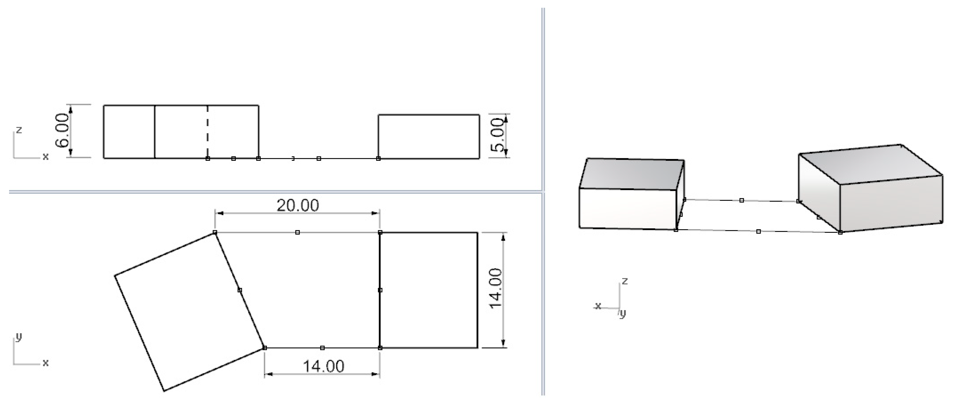
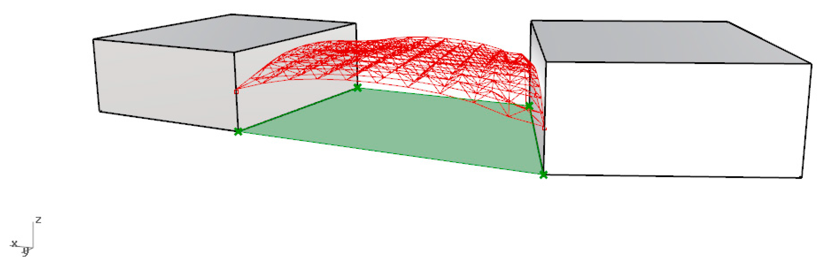
The task was to shape a covering of a marketplace, between two buildings, the orthogonal projection of which, is a rectangular trapeze (
Figure 1). The dimensions of the trapeze were as follows, the lengths of the trapezoid bases: 14 m, 20 m, the length of the trapezoid height: 14 m.
The roof structure was shaped as a curvilinear steel two-layered bar structure. As a roofing material, polycarbonate plastic sheets were used, as well as tubes for structural elements.
In order to obtain the optimal roof structure, the roof shaping was carried out using modern tools for algorithmic-aided design, working in the environment of Rhinoceros 3D (Robert McNeel & Associates). The reason for which the above-mentioned tools were selected, is that they gave the possibility to optimize the model with the assumptions of the various initial criteria.
The approach to algorithmic-aided shaping of curvilinear steel bar structures of the roof proposed in this research, was realized by application of versatile tools: Grasshopper, Karamba 3D, and Ladybug, working in the mentioned modeling software, Rhinoceros 3D. We also used advanced software for structural analysis in order to optimize the bars’ cross sections: Autodesk Robot Structural Analysis Professional 2019 [
30].
In order to generate a parametric model, the educational version of Rhinoceros 5.0 in combination with the parametric tool Grasshopper, was used. Rhinoceros 3D is three-dimensional modeling software, which enables creation of various free form shapes, based on NURBS surfaces. Whereas, its plug-in, Grasshopper, enables the creation of scripts to describe parametric models, which can be modified and visualized in Rhino’s viewport and carefully analyzed. However, Grasshopper’s plug-in, Ladybug, was used for the shadow range analysis.
Integration of geometric shaping and structural analysis was carried out using Karamba 3D. This plugin made it possible to combine parameterized complex geometric forms of various topologies, load calculations and perform finite element analysis, according to Eurocode 3. Karamba 3D is intended to be a fast tool for structural optimization [
31]. It has been used mostly in the early stage of design, although it is not limited to it. However, in the presented research, in order to perform structural analysis of complex curvilinear steel bar structures, the advanced professional software Robot Structural Analysis Professional, was used.
The validation of the functionality of the shaping tools mentioned above, as well as the benefits of their application, were accomplished by implementing them for the shaping and analysis of the responsive curvilinear steel bar structure.
The shaping strategy applied in the research consisted of the shaping of curvilinear steel bar structures by placing the structural nodes on the so-called base surface [
29]. The base surface was a minimal surface obtained as a result of the optimization, or a surface received by the method of form-finding.
3. Results of Shaping a Roof Based on a Minimal Surface
According to mathematical definition, a minimal surface is a surface that locally minimizes its area, which is equivalent to having zero mean curvature. It is a surface with the smallest possible area among all surfaces stretched on given lines.
The application of minimal surfaces in architecture is not new. They are used mostly in the construction of light roof structures. Moreover, due to their characteristics, there is a greater and greater interest in the study of minimal surfaces and their wider use to create innovative architectural objects. Moreover, the application of minimal surfaces brings measurable benefits in structural design since the minimal surfaces exhibit an optimal system of forces and stresses. It is also an important task from an architectural and economic point of view, as the application of minimal surfaces means the use of a minimal area of claddings and the minimization of costs. Due to this fact, the parametric study and optimization were conducted on the examples of spatial lattices, created based on minimal surfaces.
3.1. Shaping Free-Form Roof Due to Optimization of the Minimal Surface
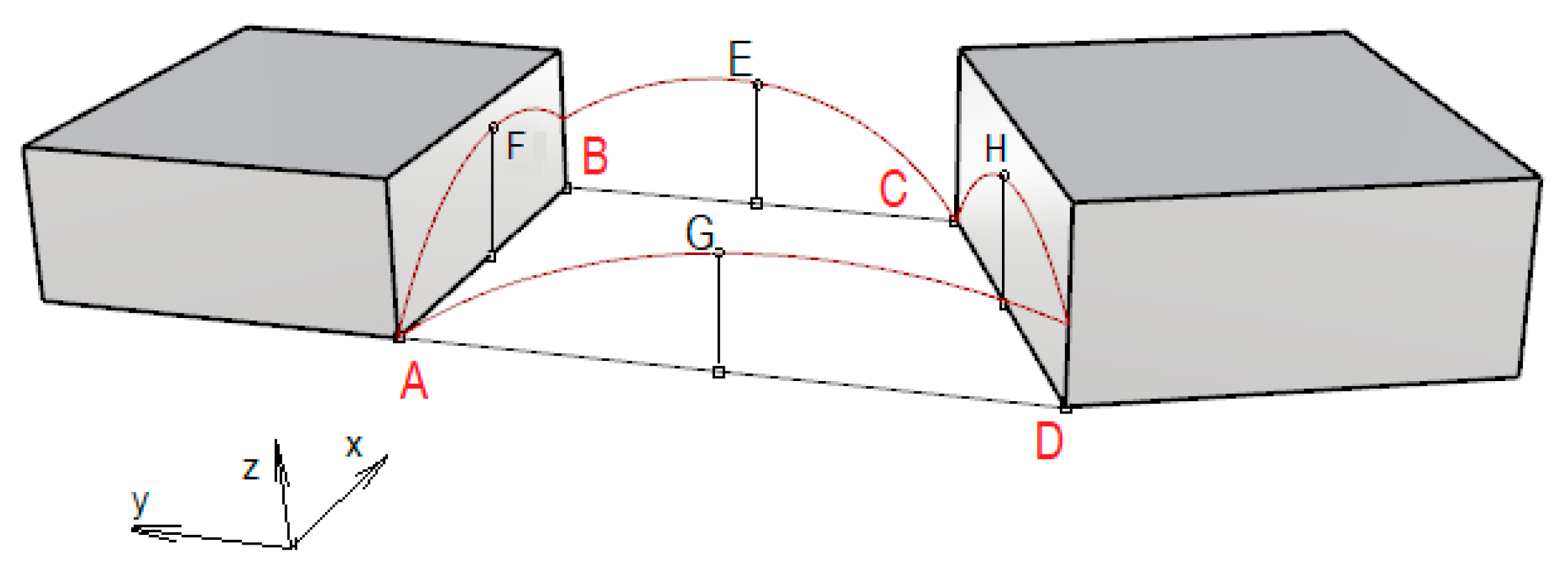
The first step in shaping the roof was formation of a minimal base surface. The minimal surface was determined as a surface stretched on four curved lines lying in vertical planes passing through the sides of the trapeze. Each line was established parametrically by three characteristic points, which could change their positions. Two of the points were the arches’ ends and the third point was an inner point of the arch. The rectangular projections of these points on the horizontal plane were, respectively, the square’s vertices and the centers of the square’s sides (
Figure 2).
The position of characteristic points: A, B, C, D, E, F, G, H, were variables that could take different values, and were defined as local increments of the co-ordinates x, y, z. The intervals of these variables were defined for individual points as follows:
Point A, B, C, D – z: 0.0 m–2.5 m.
Point F, E, G – z: 4.0 m–5.0 m.
Point E: x: 1.0 m–2.0 m (according to direction of axis x).
Point G:
x: 1.0 m–2.0 m (in the opposite direction than the axis
x),
Figure 2.
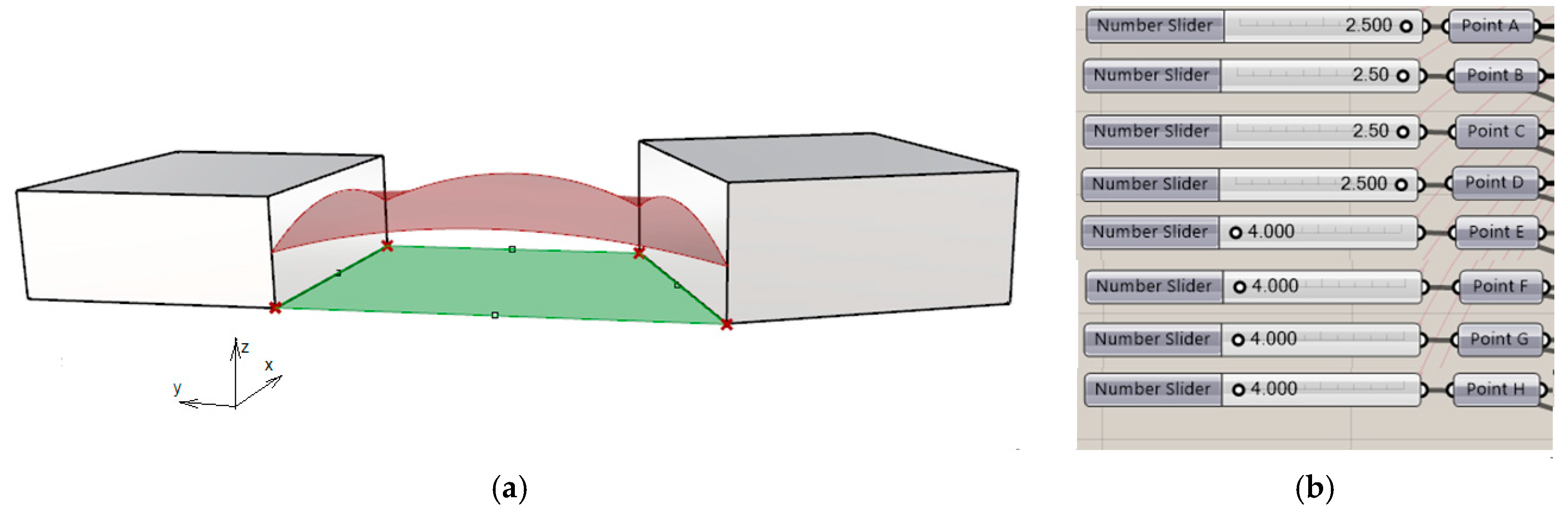
Depending on the adopted variables, we could get different shapes of arcs, and therefore, different shapes of the minimal surfaces defined by them. Consequently, this led to obtaining many alternative base surfaces. Some of them are presented in
Figure 3.
The optimal surface selected from the possible alternatives, was the surface with the smallest area, as it could guarantee the minimum amount of materials used. In order to find such a surface, the optimization process was performed in Grasshopper environment. As the optimization criterion, the minimum surface area was assumed, while the variable parameters were the individual positions of the points. Due to the optimization carried out, a minimal surface area equal to 263.042 m
2 was obtained for the surface, as well as characteristic heights of the points (coordinate
z), presented in
Figure 4. Additionally, both points, E and G, were moved horizontally one meter outside the trapeze bases, according to axis
x.
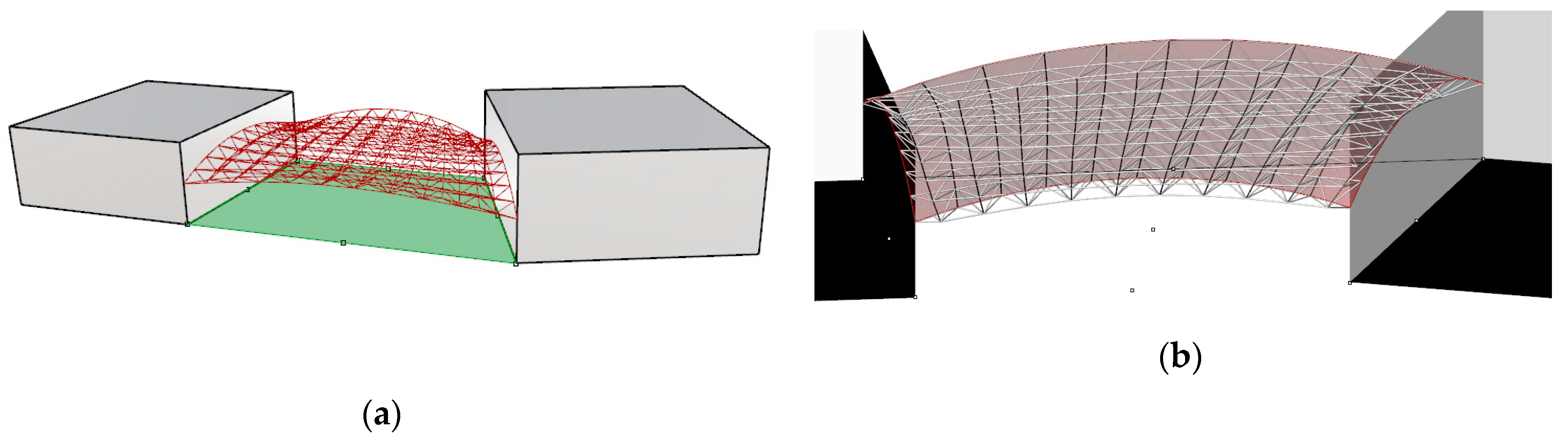
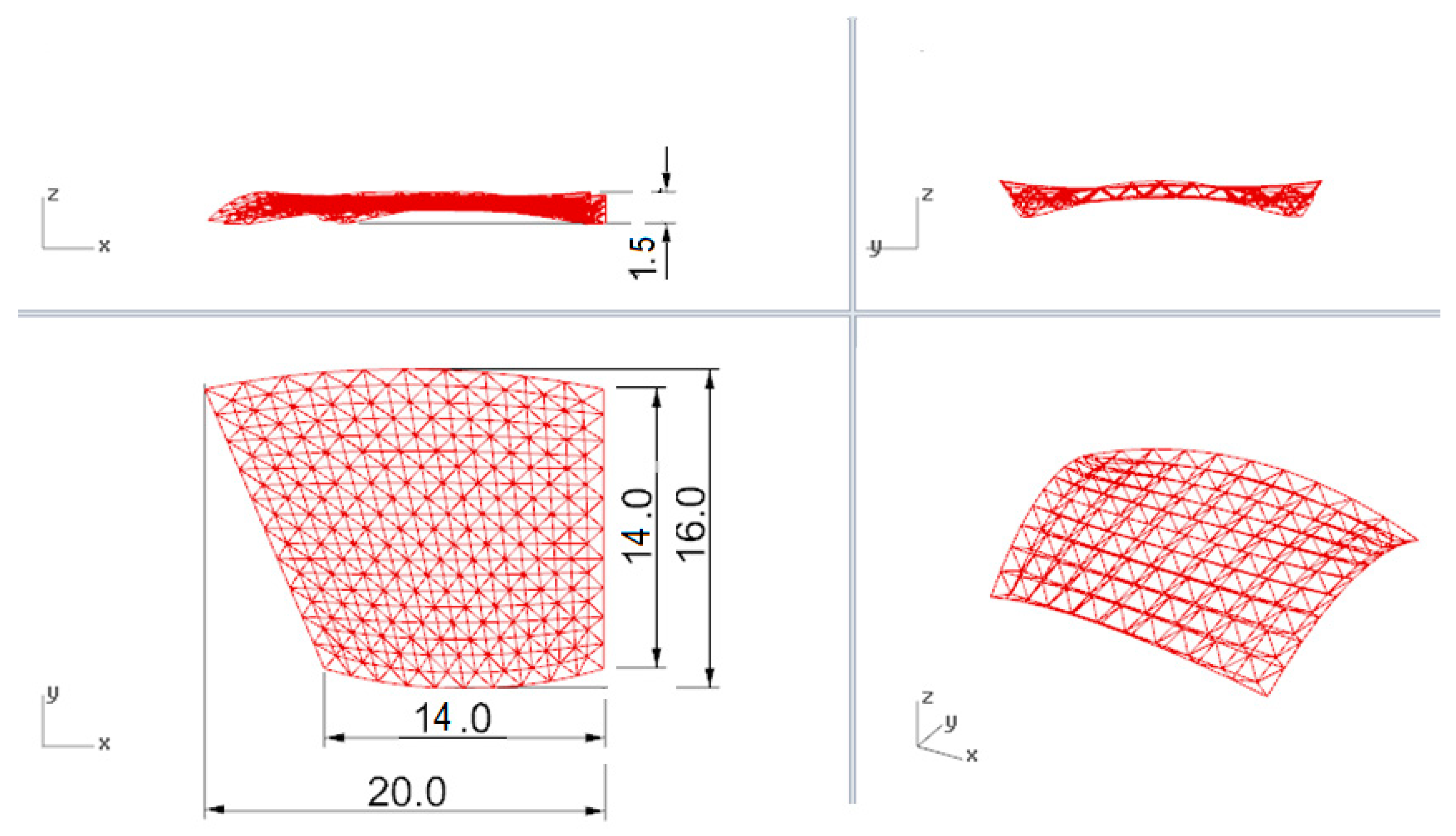
This optimal surface constituted a base surface in order to create the roof’s steel bar structure. The multi-layered grid on this surface was applied in such a way that the structural nodes of the top layer were included in the surface. In order to distribute the nodes, the surface was divided into the same number of segments, equal to ten in the
x and
y directions (
Figure 4 and
Figure 5).
The orthogonal projections with dimensions of the considered structure are shown in
Figure 6.
3.2. Finding the Roof’s Shape by the Form-Finding Method
Another way to shape the minimal base surface and the roof structure is using the so-called form-finding method. Historically, it is an quite an old process, although the tools for the realization of it have been developing over the years. There are two form-finding techniques: the first one it is a method, which uses hanging models to simulate compressive forces; and another one is the method of the minimal energy shapes of soap films. The hanging model method can be applied to simulate the behavior of a family of structures known as funicular structures. Thus, finding the shape of the structure based on the hanging model method means that the form found is adjusted to magnitudes and positions of the forces acting on it. This method is mostly used in order to shape structures, which work mainly in tension and compression.
The form-finding method has become very popular in recent years, mainly as a method for the shaping of free-form structures. Nowadays, due to the development of modern computerized modeling and calculating tools, which give the freedom to explore the design space, it can be realized automatically in various ways [
32]. In the case of parametric shaping structures, form-finding is determined as the process in which parameters are directly controlled in order to find an optimal geometry of a structure, which is to be in static equilibrium with assumed loads. The load used for form-finding is usually the structure’s self-weight, however, they can also be other external loads.
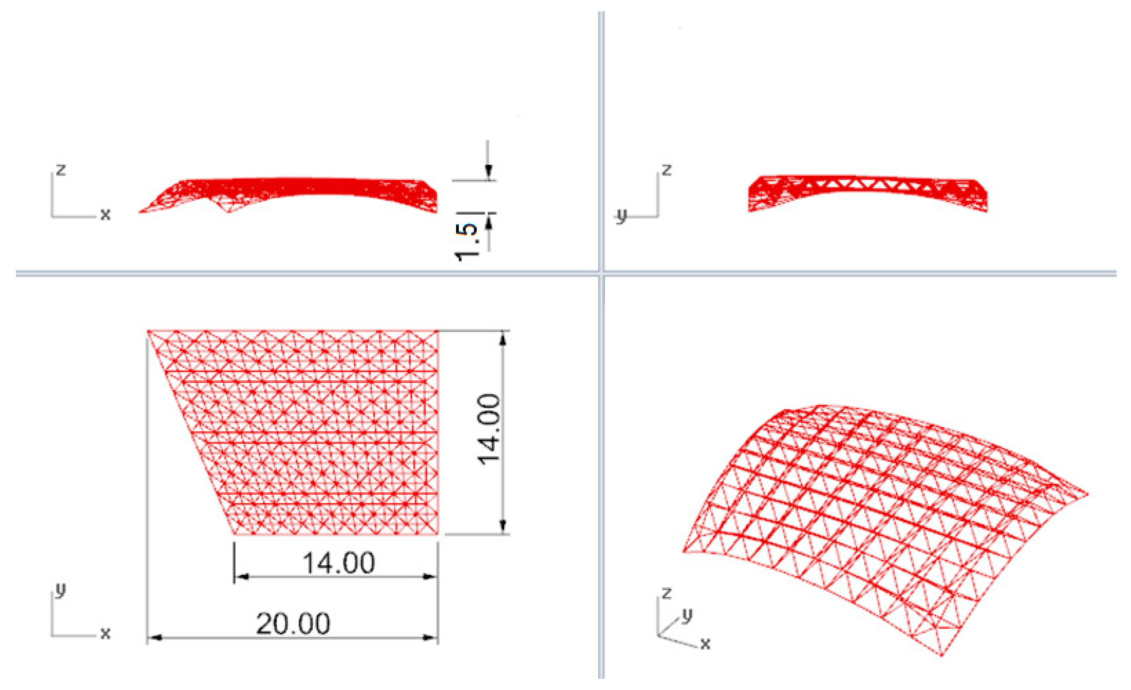
In the considered case, the roof’s base surface was generated as the form found over the trapeze-shaped place, by means of plug-ins working in environment of Rhinoceros 3D. During such a form-finding process, the structural load direction had been inverted in order to achieve a proper arrangement of the shaped structure. The height of the roof during simulation was assumed to be the same as in the previous case, which was 1.5 m. On the generated surface, a two-layered grid structure with the same division along axes x and y, like in the previous case, was applied (
Figure 7). The structure was placed at the same height as the structure presented in
Section 3.1.
The orthogonal projections with dimensions of the obtained structure are shown in
Figure 8.
3.3. Analysis of the Shadow Created by a Set of Connected Buildings
Due to the fact that the function of the shaped roof was not only to provide protection against atmospheric precipitation but also against the sun in the summer period, the shadow produced by the roof, together with the adjacent complex of buildings, was analyzed. The aspect of the construction of the shadow cast by the building complex is presented in [
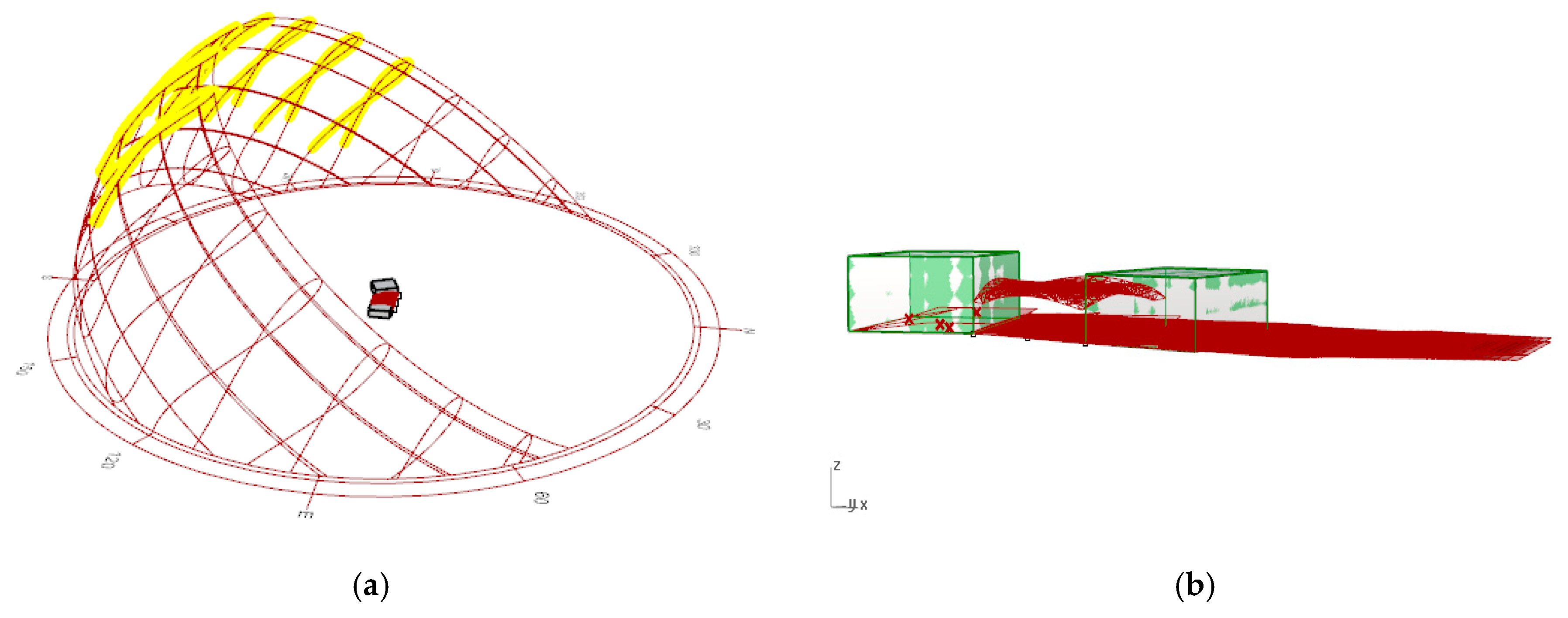
33]. In our research, the analysis was carried out for the period from March to September, during the hours 10 am to 5 pm by Grasshopper’s plug-in, Ladybug. For the analysis, the city of Warsaw was assumed as the location of the building complex and the complex’s position was with respect to the north direction, as shown in
Figure 9. The analysis showed that the complex of buildings with the shaped roof, presented in
Figure 5, produced much more shadow during the considered period, than the complex presented in
Figure 7. The amount of shadow generated in the analyzed period is shown graphically in
Figure 9.
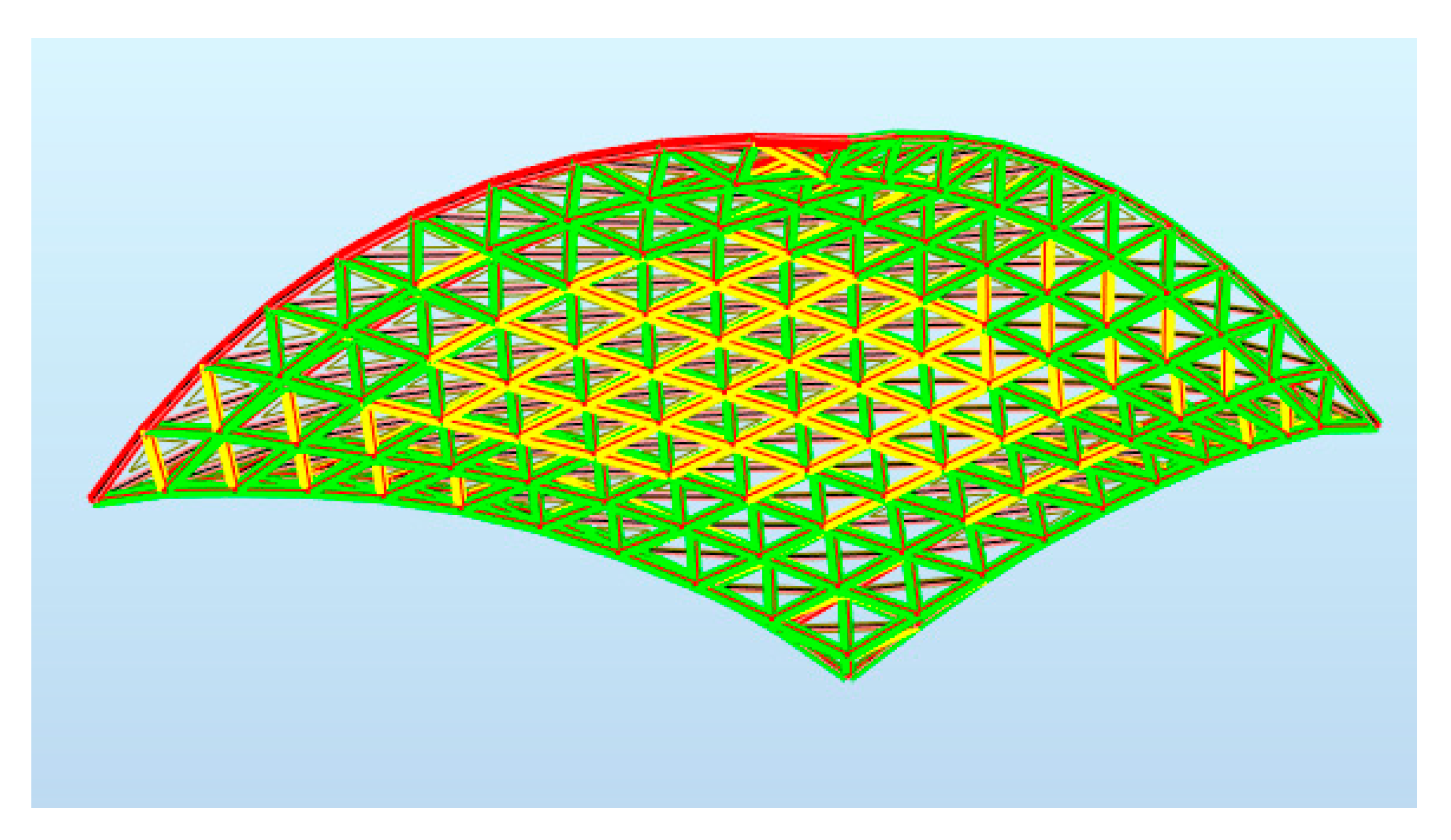
3.4. Optimization of the Structural Members’ Cross Sections
We carried out structural optimization using the Autodesk Robot Structural Analysis Professional 2019 software. The border conditions regarding the wind and snow zones were assumed according to the location of the building objects. Due to the shape of the roof, that is, its mostly flat nature, the snow load was assumed to be the same as for the shed roof. However, due to the roof’s installation, that is, its adherence to adjacent buildings, the possibility of a snow drift has been included in the calculations [
34]. The maps on bars showing the distribution of the axial force
Fx are presented in
Figure 10.
The bars of the structure were divided into three groups for the dimensioning: The top truss bars, the bottom truss bars, and the truss diagonal bars. The structure was optimized assuming as the optimization criterion the mass of the structure. Moreover, the structure was optimized for two cross-sections: circular and square. The results of the optimization are presented in
Table 1.
The considered structure was composed of 221 nodes and 800 members. However, the total mass of the shaped structure was equal to 186,525 kg in the case of members with box hollow cross-sections and 185,621.286, in the case of round tube members. Due to this fact as the most efficient structure, it has been chosen the structure with circular hollow cross-sections as the lighter structure than the structuer with box hollow cross sections.
4. Discussion
The use of Rhino and Grasshopper gave much creative freedom and flexibility in shaping. Due to this fact, it was very convenient to use during the initial design process. In addition, to the advantages of the possibility of the creation of many alternatives of geometric forms by Grasshopper, there was a huge potential for combining parametric shaping with interactive evolutionary optimization.
The conducted research on shaping the roof over the market square, using algorithmic-aided shaping, has shown that a comprehensiveapproach to shaping is possible. Therefore, as early as possible, we could take into account many aspects that affect the future form and work of the structure. These aspects can be conditions regarding the planned function, reliability, load-bearing capacity, resistance to exceptional impacts and natural environment.
Moreover, defining the geometry of the shaped structure by means of the algorithms, gave the possibility of various modifications and obtaining a virtually unlimited number of geometric forms. Especially, in the case of curvilinear steel bar structures, which are characterized by a variety of topologies, this is of great importance. In turn, the creation of a structural model using the Karamba 3D plug-in gave the possibility of an initial verification of the geometry, in relation to the structural requirements, which led to effective shaping.
5. Conclusions
The form of the roof received by algorithmic-aided shaping has been appropriately adapted to environmental conditions, whereas external conditions have caused the adaptability of the structural members of the roof. Moreover, the choice of the minimal surface as the base surface for the design of the roof form brings great benefits. First of all, the amount of cladding needed to make the roof could be reduced. In addition, the use of a minimal surface as the surface for the location of the structural nodes can influence the beneficial arrangement of forces in the structure. Thanks to this, it was possible to reduce the cross-sections of the bars, and hence the mass of the structure. Dimensioning was carried out for two bar cross-sections, which also gave the opportunity to choose the optimal cross section, due to the mass of the structure.
The research presented in the paper shows how using the tools for generative design, the process of shaping curvilinear steel bar structures, could be potentially improved in order to create responsive structural forms that meet both architectural and structural requirements.
Due to the fact that, in the case of bar structures, the unification of structural members is very important, the optimization of this issue will be the subject of further considerations of the author.


