1. Introduction
During sudden earthquakes, extreme ground excitation creates a huge ground acceleration which may cause severe structural damage to multi-story buildings. To avoid such structural damage, the strength capacity of the buildings needs to be increased. However, increasing the strength of a building in both an indefinite and traditional sense poses several logistical and economical challenges. Regions with high seismic activity experience acceleration forces that can exceed gravitational acceleration up to two times. Designing conventional fixed-base (FB) buildings to withstand such level of forces will lead to exorbitant construction costs. Although the earthquake itself cannot be controlled, its effect on the structure can be controlled by minimizing the effect of the motion of the foundation on the structure above using bearing isolation. The isolation system provides additional flexibility and energy dissipation capability by installing between the foundation and superstructure [
1,
2,
3,
4]. The study of Chimamphant and Kasai [
5] presented the comparative response and good performance of base-isolated rather than fixed-base structures. Seismic fragility assessment of asymmetric structures was dealt by Tajammolian et al. [
6] with TCFP bearings under near-field earthquakes. A significant reduction of dynamic loads induced by seismic activity at structural bases were shown due to isolation strategy by Micheli et al. [
7].
Lead rubber bearings, a type of elastomeric bearing introduced a dramatic shift in the thought process behind the design of base isolated (BI) structures [
8]. Several studies examined their ability to act as base isolators during seismic activity and have all explored the seismic performance of lead rubber bearing (LRB)-isolated multi-story buildings [
9,
10,
11,
12,
13,
14]. Moreover, base isolators that incorporate hardening behavior were developed under increased loads and indicated them in practical use case scenarios (moderate earthquake risk sites) up to four story medium-rise buildings [
15,
16]. Such bearing isolation can be a potential alternative to the complex and expensive approaches [
17] to increase the strength of the structural element as it significantly decreases the element forces.
Although the use of isolators may be familiar in different countries of the world, bidirectional earthquake considerations have rarely been investigated for medium-rise to high-rise buildings aimed at checking the performance of varying lead rubber bearing systems. Response spectrum methods have also not been dealt with simultaneously in analyzing the isolated behavior of such buildings. The seismic performance of multi-story buildings can be best evaluated using response spectrum analysis (RSA) which is relatively rapid, concise, and economical when compared to the time history method [
8,
18].
Therefore, this study assessed the viability of using lead rubber bearing devices at the structural base of buildings and the performance of isolated buildings with a fixed building system for varying LRB categories. An initial set of tests developed to examine the viability of incorporating isolators into building design was conducted using equivalent static analyses. Dynamic analysis was also carried out by RSA for different configurations of structures as well. Design parameters for the isolators of this building different number of stories were then evaluated using SAP 2000 (CSI, Berkeley, CA, USA) [
19]. The displacement behavior, shear force, story inertia and story accelerations of FB and BI buildings at different levels were assessed to get an idea of selecting the potential lead rubber bearing system.
2. Materials and Methods
2.1. Configuration of Structures
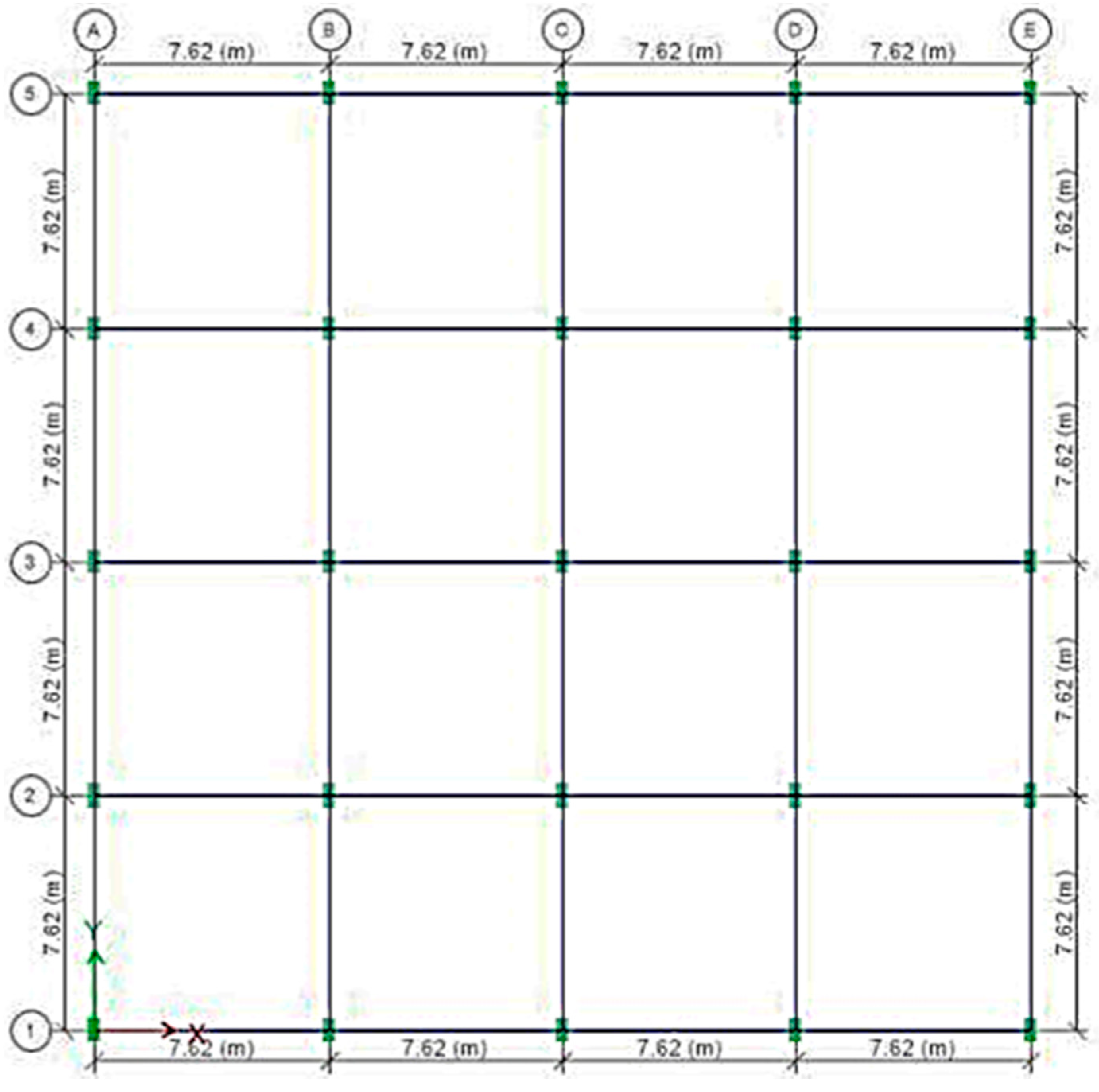
A variation of four moment resisting reinforced concrete frame buildings of four spans @7.62 m centerline to centerline (c/c) bidirectionally having 4, 6, 8 and 10 stories @ 3.05 m c/c were considered. The typical plan areas of the modelled buildings are as shown in
Figure 1. The technical base story had 1.83 m height. Fundamental natural periods of the 4,6,8 and 10 story buildings were assumed to be 0.50, 0.75, 0.80 and 1.00 respectively, which allowed the possibility to use similar isolation systems for all buildings.
Table 1 shows the structural parameters, boundary conditions and loading information of the building models.
The FB buildings were regarded as having fixed support conditions. Base isolators were incorporated and tested against all possible variations of the model building being studied. Each base isolator was assigned in between the foundation of the building and base mass at the bottom and top ensuring all properties in the spring. The structural system considered several assumptions. The superstructure of the building behaves elastically during earthquake excitation. Total structural assemblage is excited by seismic motion in both the horizontal and vertical planes. Base isolators bear vertical loads undergoing no vertical deformation. A bi-linear model was chosen for the LRB as an isolation device.
2.2. Incorporation of Lead Rubber Bearing (LRB)
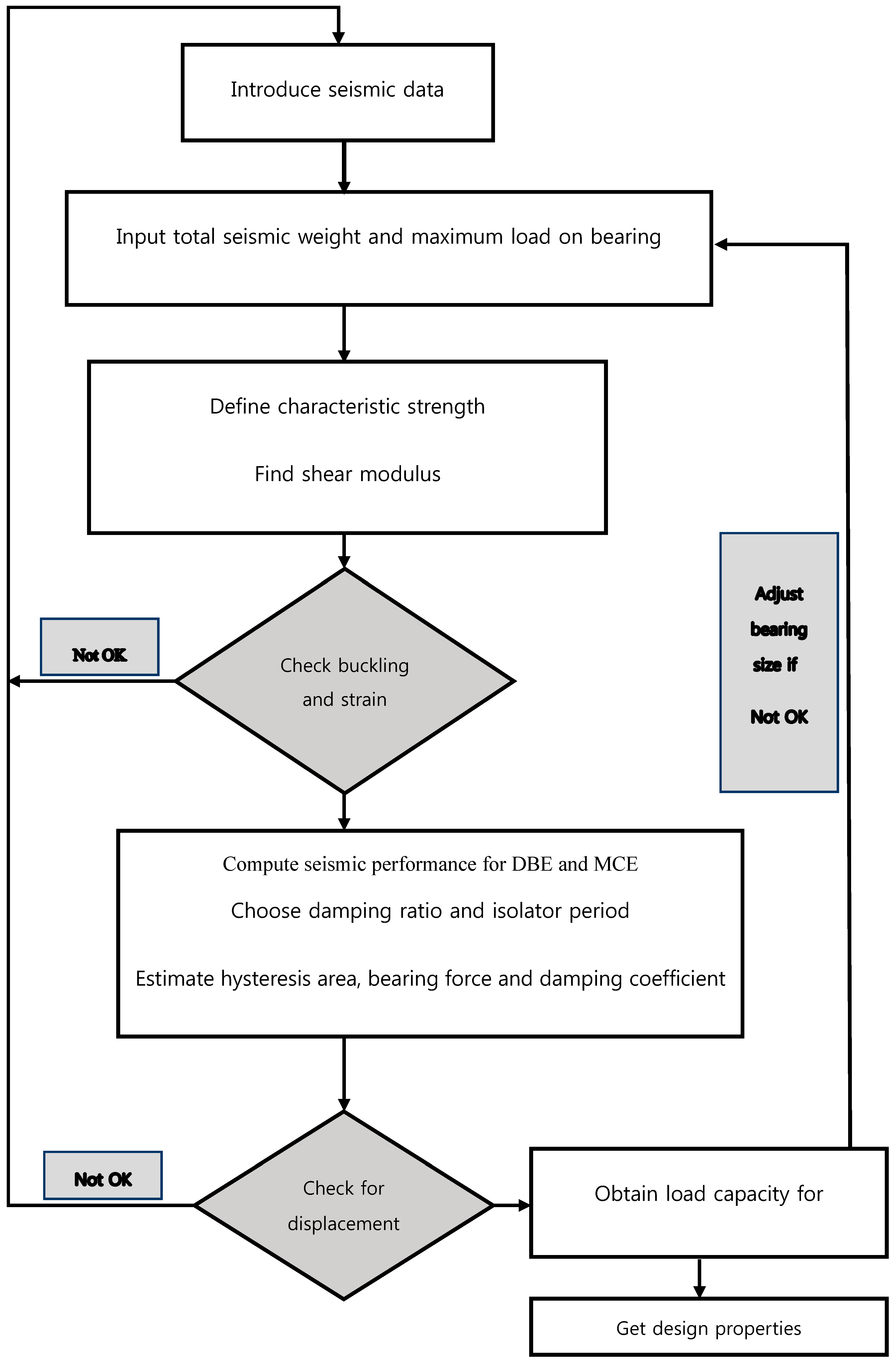
The design of lead rubber bearing isolators were undertaken considering the vertical loads and essential properties. The gradual procedure of designing the LRB device was presented by the flow diagram in
Figure 2. The considerations mentioned in
Table 2 showed the parameters and range of the LRB properties used in this study. The mechanical properties of bearing material included the shear modulus, the elastic modulus, and the material constant and ultimate elongation were dependent on shear modulus [
20].
The iterative progressions were adopted to assess and adjust the varied types and layouts satisfying the design requirement. Isolators were uniquely designed and identified by both plan size and rubber layer configuration plus lead core size. Starting values are selected as per project performance specifications. After assigning stiffness values to the isolators, the isolated structure was analyzed with SAP 2000 (CSI, Berkeley, CA, USA) [
19].
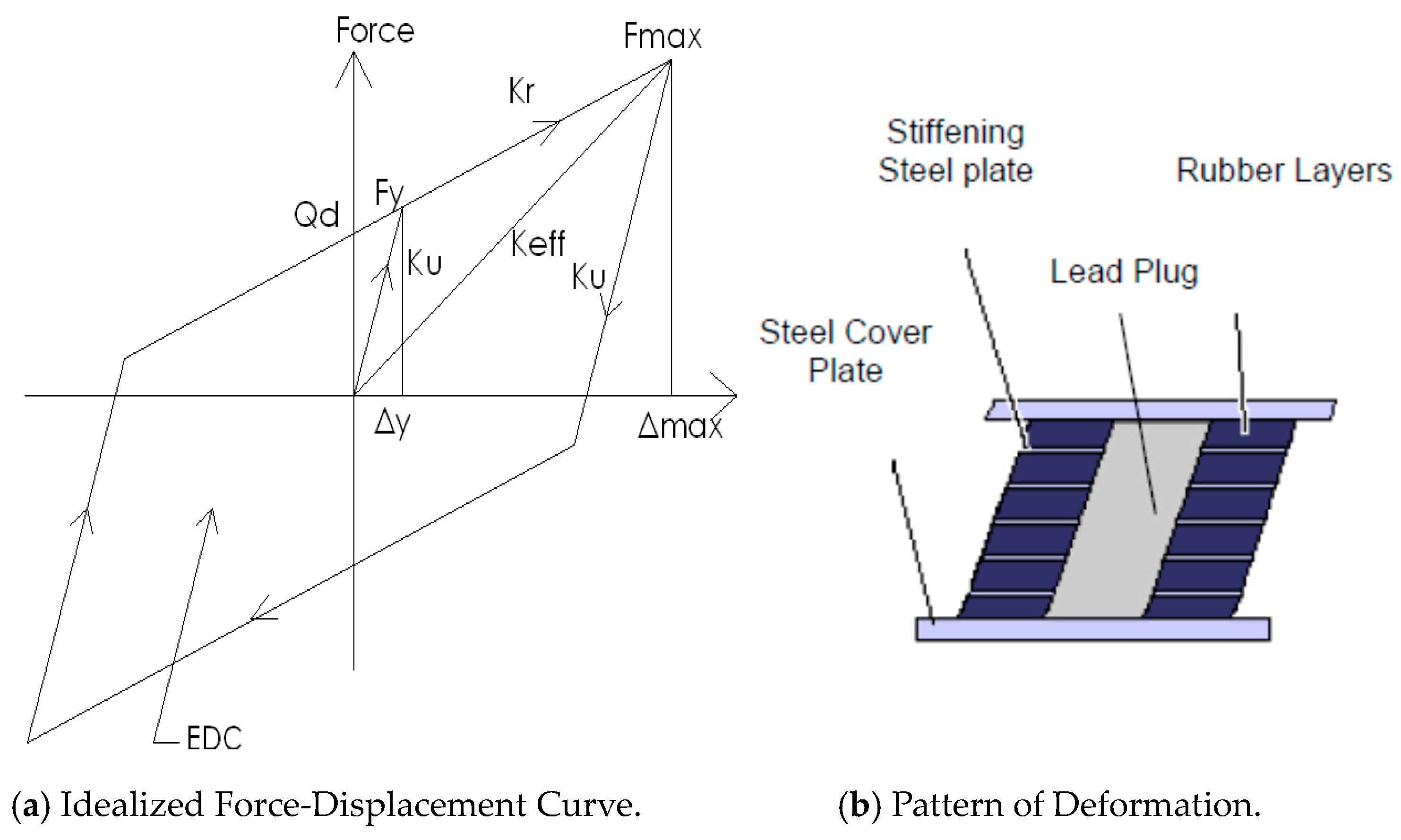
The LRB consists of two steel bearing plates that house a rubber-lead plug-rubber layered interior. LRB deformation behavior was simulated using the bi-linear hysteresis loop mode. The three parameters characterizing this model are as follows: (i) characteristic strength, (ii) post-elastic stiffness, (iii) yield displacement [
21].
Figure 3a depicts an idealized hysteresis for LRB while
Figure 3b demonstrates the LRB deformation behavior when under load. Equation (1) gives the relationship between force intercept at zero displacement and the isolator’s yield strength.
where, yield stress depends on vertical load and lead core confinement. Post-elastic stiffness is given by the following equation:
The elastic (or unloading) stiffness is defined as follows [
22]:
The hysteresis loop area can be found from the following expression:
2.3. Numerical Study
To simulate the behavior of LRB, a total of 12 LRB systems were used in this study. For each system, the elastic stiffness (K
u) and yielded stiffness (K
r) were defined as described in the previous section and as shown in
Figure 3.
Four effective periods of 1.5, 2.0, 2.5 and 3.0 s were used in each LRB system. Besides, three values of Q
d (0.05W, 0.075W and 0.010W) were used. Where, Q
d is defined as the yield level of the LRB corresponding to zero displacement as shown in
Figure 3. The range of the effective damping is from 8% to 37% and depends on Q
d. Table 3 shows a list of LRB system properties used in the evaluation including the hysteresis parameters adopted for modeling.
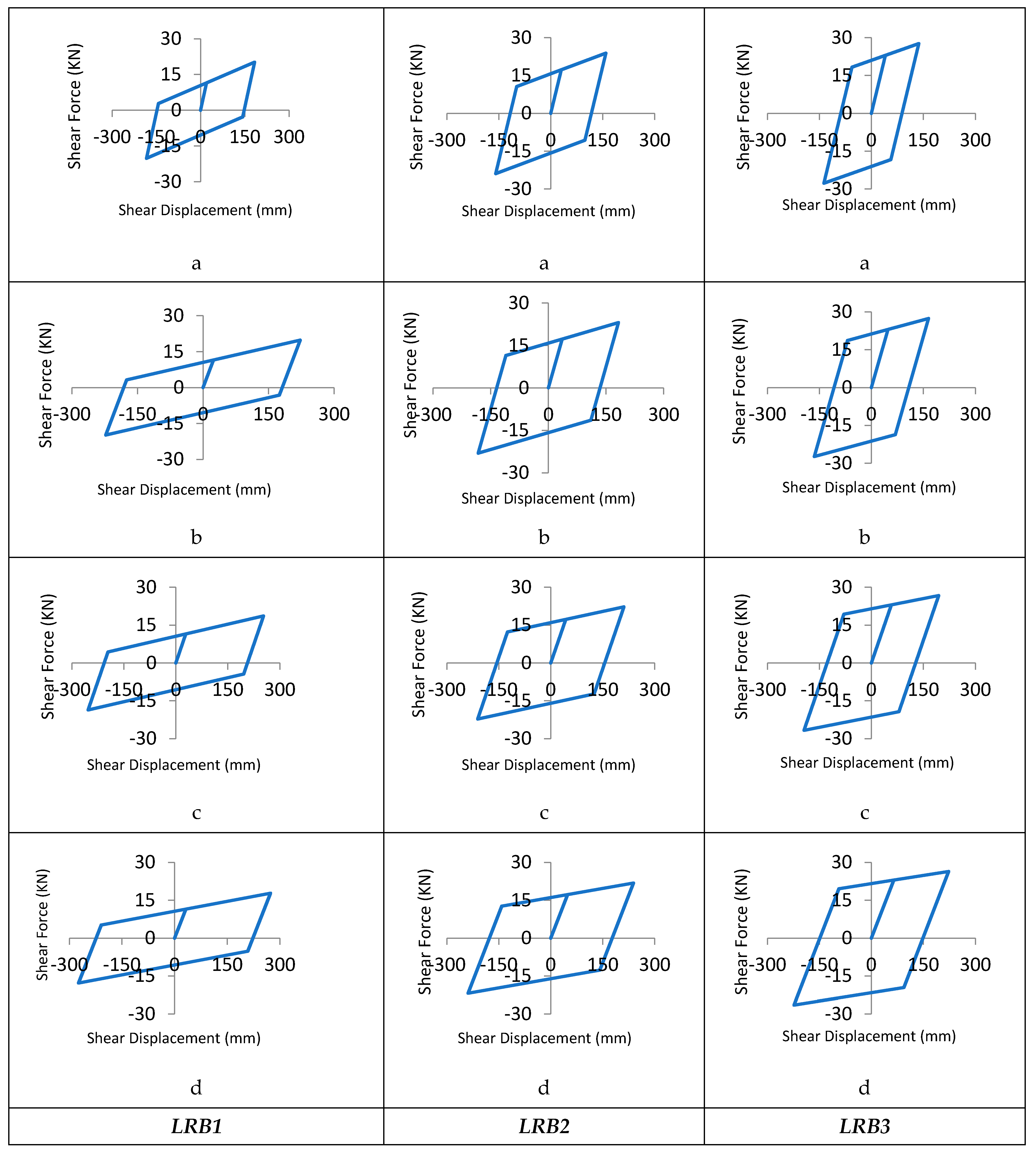
The isolation system was designed with seismic load in consideration choosing the S
3 soil category. Assumptions made for the site include being located in a Z = 0.15 seismic zone within 15 km from a type A fault. Two load levels were used for bi-directional seismic excitations. The first was the design basis earthquake (DBE) used to evaluate the structure and the second was the maximum capable earthquake (MCE) to obtain maximum isolator displacements. Using theses parameters, all the hysteresis curves were estimated and used throughout the design process. As references, the hysteresis curves for 10 story building were given in
Figure 4 because the LRB devices sustained maximum loading for this case. All LRB isolators produced a bi-linear force displacement function that includes measures of elastic stiffness and yielded stiffness.
2.4. Finite Element Method
The evaluation of isolated structures was conducted using two finite element analysis (FEA) methods namely, (1) static analysis and (2) response spectrum analysis. Designing isolator is an iterative process based on initial assumption of the effective stiffness of the LRB and as per the calculated displacement results, the effective stiffness values were then adjusted. For every three-dimensional multi-story building analysis, accelerations and displacements for each level were saved at all stories. Recorded values were then run through the modelling process to obtain isolator displacements and base shears.
In the equivalent static analysis, (i) the seismic lateral loads by selecting for factors such as Z, R and soil profile; (ii) the lateral load for wind with essential coefficients and formulas were determined according to the Uniform Building Code (UBC, 1997) [
24]. Minimum levels for design displacements and forces were obtained by performing static analyses on all seismic isolation designs. This information aids in both preliminary designs of isolation systems and includes information that aids in the design review process when attempting to design for specific circumstances. Furthermore, dynamic analysis is also required to obtain the actual behavior of a structure and a potential technique for that is RSA.
2.4.1. Equation of Motion
The equation for motion of the super structure remain constant across all base isolation systems and is represented as follows:
is the vector of displacements at the slab related to the base mass; is the vector of the base displacements relative to the ground and is the ground acceleration vector.
2.4.2. Response Spectrum Analysis (RSA)
The dynamic analysis method, RSA, has good potential to predict a structural system’s straining actions. Linear analysis equations were transformed into a normal coordinate system and RSA was performed using mode superposition. The complete quadratic combination (CQC) method was used to combine modal values while directional combination was conducted using the SRSS method. In the response spectrum method, the use of the modal superposition technique is only applicable for linear analysis.
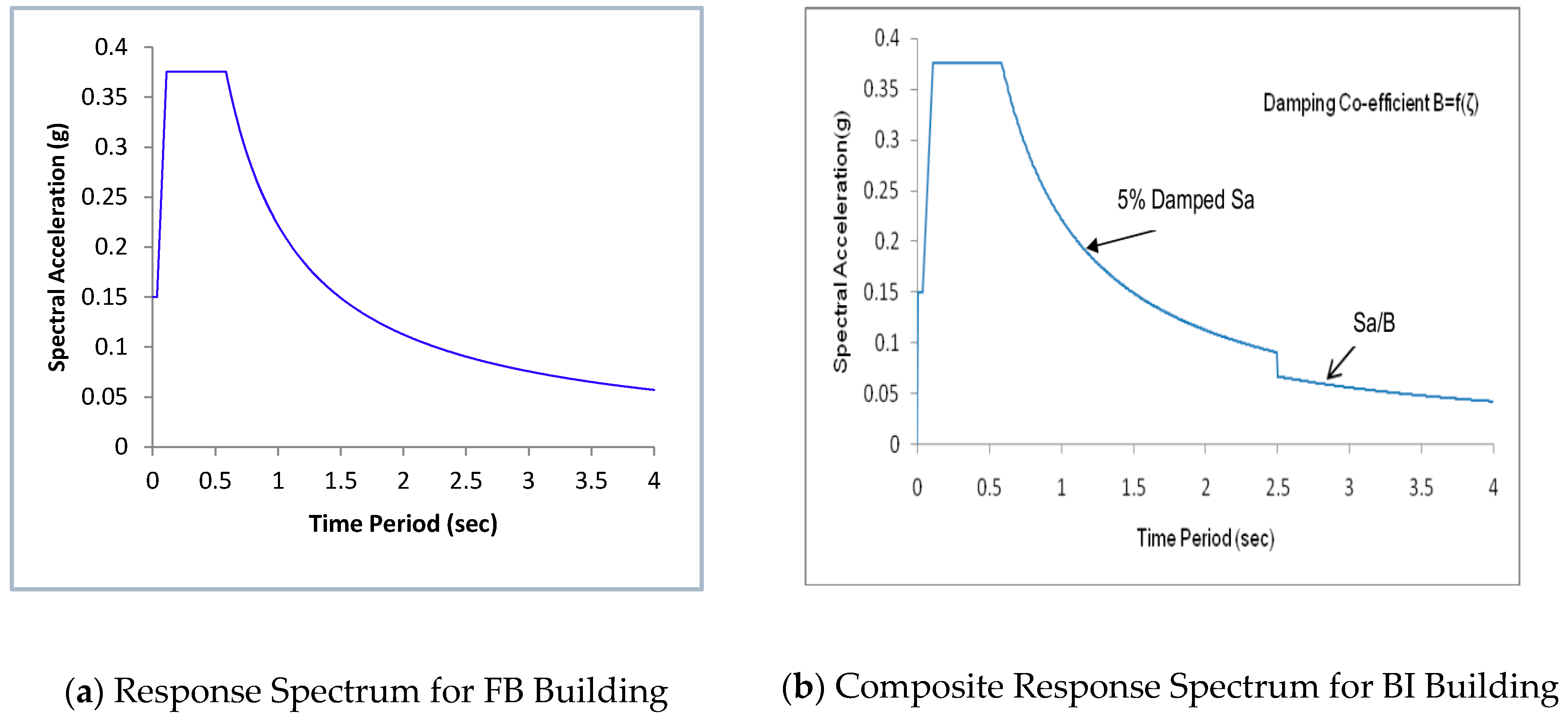
In this investigation, dynamic analyses of FB buildings were carried out by RSA imposing the response spectrum shown in
Figure 5a. However, during the RSA of base isolated buildings, the response spectrum was adjusted to contemplate the damping effect of the isolators using a composite spectrum [
24]. The 5% damped composite spectrum was reduced by the B factor in the isolated modes (
Figure 5).
3. Results and Discussion
The crucial tools to explore the dynamic responses of base-isolated buildings are the design base shear, lateral displacements, story inertia forces and story accelerations. Therefore, such parameters are evaluated to check the structural behavior of selected fixed based and isolated buildings after the verification of the isolation and structural system.
3.1. Verification
The selected structural time period for isolation was less than 1.0 s, which is considered as a suitable value within reasonable limits [
20]. The building site permitted horizontal displacements at the base of more than 200 mm while base shear caused by wind disturbances (lateral loads) was smaller than 10% of the building’s weight as required [
25]. Thus, isolators may serve as alternatives to FB designs when used to stabilize the base of the structures.
Prior to evaluating the isolated structure’s performance two conditions had to be satisfied: (i) isolation bearings had to support required loads, (ii) overall performance of the isolation system had to be satisfactory. The ability of isolation bearings to carry the loads was checked using the factors of safety (FS). As FS exceeded 1.0, the ability of the bearings to safely carry the loads was considered satisfactory. The status of the isolation bearings with the factors of safety are within the recommended limits.
Isolated structure performance under both the DBE and MCE conditions was evaluated. Maximum (top) displacement results were less than the static isolator allowable design displacement of 292.61 mm for an MCE, which indicated a satisfactory performance of the isolator properties.
The elementary structural model using the isolation system have already been published [
8]. Similar building configurations have been chosen for the selected seismic prone building structures with identical environmental conditions for alternate analysis technique. The study extends the investigated as mentioned in detail to find out suitable alternative of lead rubber bearing system to be implemented in the structural base for getting better benefit using more simple response spectrum analysis.
3.2. Design Base Shear
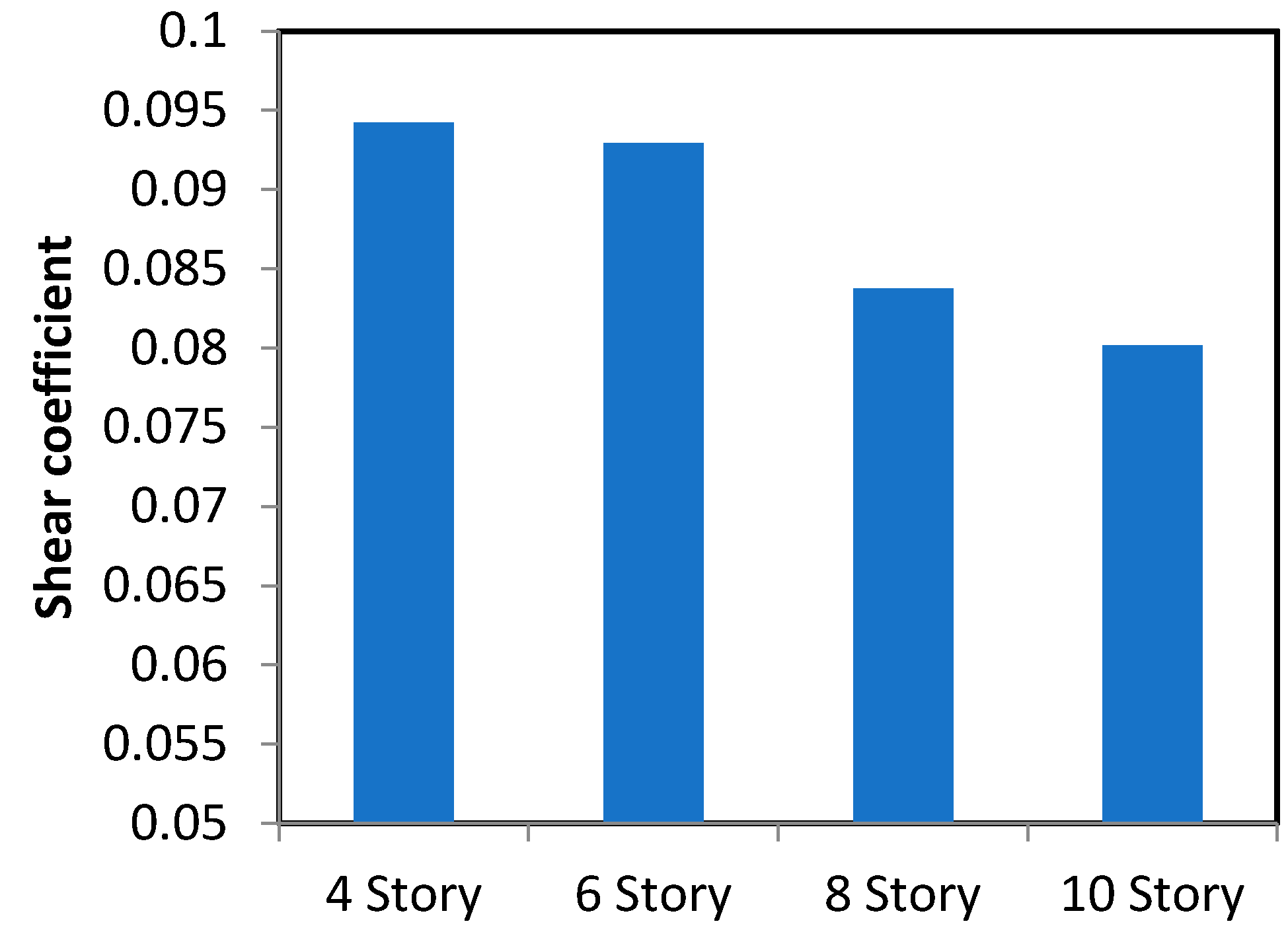
Among the buildings’ performance parameters, the imperative response is the base shear coefficient defined as maximum design base shear normalized by the structure’s weight. The shear force at base reduces more substantially than the FB building design base shear for RSA due to the flexibility offered by bearings. For the 10-story building, the base shear was 2778 kN in an FB building whereas, base shear was reduced to 2303 kN in an LRB isolated building a 17 % reduction of shear.
Figure 6 plots the response spectrum results of base shear coefficients for a variety of LRB type buildings each at a constant period of 1.5 s. This demonstration of building flexibility shows a shear reduction trend of 10–20% for shorter buildings. This data demonstrates that the building period is directly correlated with building flexibility where base shear coefficients inversely correlate with longer building periods. This is due to the structural configuration and hysteresis behavior of the bearings.
3.3. Lateral Displacement
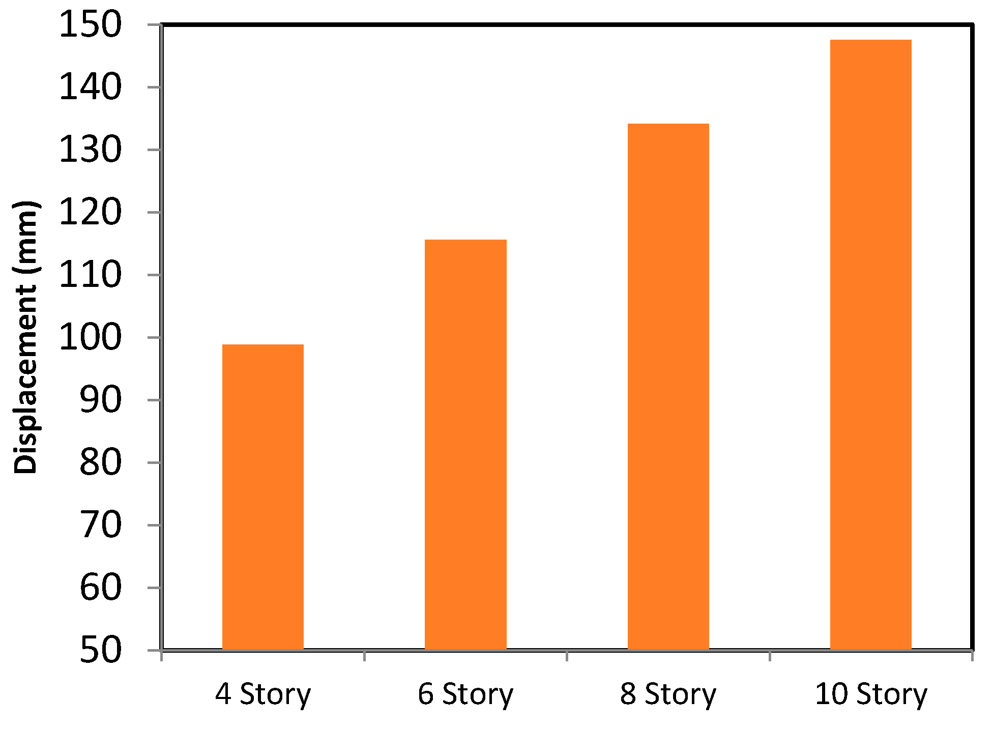
In the case of FB buildings, there is no base displacement but a significant translation at the upper stories. However, BI structures offer almost uniform lateral displacement at base as well as whole upper structure maintaining the displacement within acceptable limits. The trivial relative displacement in the building stories demonstrates that structures can withstand comparatively high seismic tremors in a safe, economic and efficient manner against vulnerable earthquake motion. Obviously, lateral displacement at base for BI buildings indicates the superstructure translation or shift along the structural base.
Figure 7 plots the lateral displacement results based on the maximum values from the response spectrum analyses for lead rubber bearing LRB 1a. The output ensures that there is a significant lateral shift of the superstructure when LRB is inserted whereas FB structures remain in their positions at base level. Results also demonstrate that there is no effect of a structure’s period on lateral shift above the isolator level despite the momentous influence associated with the gradual rising of a building’s elevation.
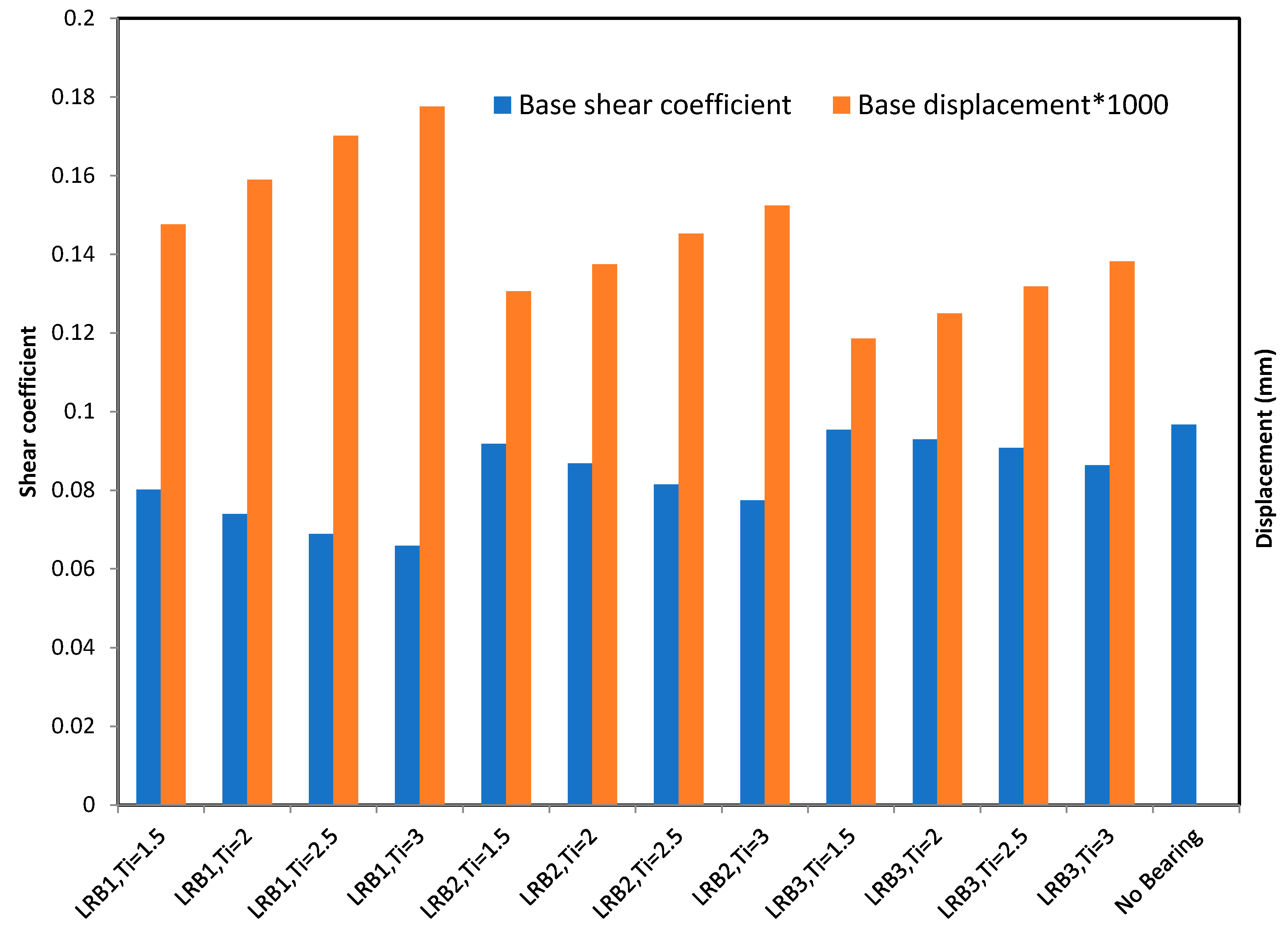
Various kinds of LRB devices have various effects on the displacement and shear force. This is because of different characteristic strengths, isolation periods as well as damping ratios which might alter the behavior of lateral displacement and base shear. Hence, obviously no specific bearing device seems to be feasible to satisfy every possible purpose such as shear control or displacement control. The base shear coefficient and isolator displacement values of the selected 10 story building are shown in
Figure 8 for the 12 considered lead rubber bearing systems aimed at assessing its selection satisfying the design requirements.
It has been observed that the LRB1d results in lower base shear coefficients and it increases with lower isolation period in same characteristic strength. Subsequently, both LRB2 and LRB3 follow such a sequential manner with respective descending isolation period values. In general, it is observed that systems with minimum base shear coefficients have higher displacements. Such behavior confirms the idea that the higher displacement means offering more flexibility of the superstructure which obviously lessens the lateral shear in base. The data also demonstrates that in hysteretic systems when period is increased incrementally, displacement increases and viscous damping decreases. Moreover, LRB3 systems with relatively short isolated periods are the most efficient at controlling isolation system displacements. Similar patterns are observed for LRB2 and LRB1 systems with efficiency decreasing incrementally as period increased, respectively. It is obvious that the high characteristic strength of isolation device controls the superstructure displacement. Most of the systems having minimum displacements have relatively high base shear coefficients and accelerations.
3.4. Story Inertia Force
Inertial forces, as obtained by RSA, are distributed across the longitudinal plane of the structure and are used to define the design shears for each story.
Figure 9 plots distributions of four different building configurations of BI cases with the LRBs each having an isolator effective period that increases sequentially by Ti = 0.5 s. Modal inertia forces are defined as the product of spectral acceleration, participation factor, and mass.
The higher the isolation period of the LRB, the lower the inertial forces of BI buildings. From the story inertia values for different building periods from the selected buildings, it was shown that LRB1 reflects the minimum values for higher isolator periods to larger at lower Ti. These are followed by variations of LRB2 and LRB3 systems.
3.5. Story Acceleration
One factor that plays an important role in diminishing seismic damage to non-structural components is the ability to dampen story accelerations. Therefore, as this indicator, story acceleration is chosen which can be treated as normalized inertia force as well.
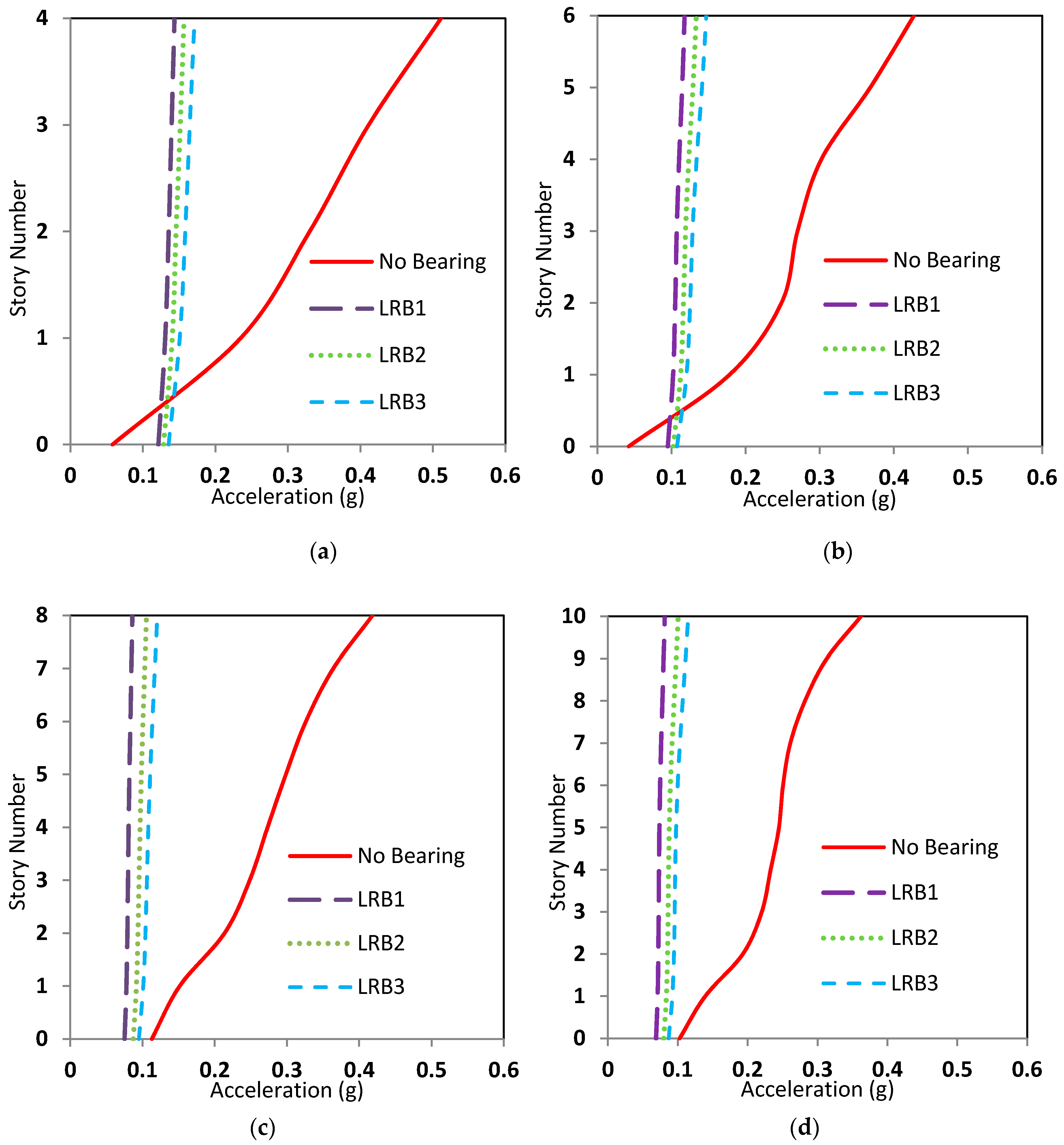
Figure 10 plots the story acceleration distributions for different BI configurations at different isolator effective periods as considered for inertia forces. The distribution of these story accelerations within the height of the structure defines ultimately the lateral forces at each level and the total overturning moments on the structure.
Building accelerations without devices increased almost linearly with height. Values were nearly equal to base level at lower stories while maximum ground acceleration was achieved at the roof of the buildings. Whereas for BI cases, the bottom level maximum accelerations increase towards the top-level maximum acceleration with relatively lower increments. The reduction of story acceleration for response spectrum varies 30% at lower stories to 70% at upper stories.
All plots show the maximum values and include building accelerations with no isolation to serve as a benchmark comparison. For ground level acceleration, an elevation of 0.0 was 0.135 g and varied non-linearly on upper stories for a low-rise building but is identical with trivial deviations from the first level for a higher elevation structure.
Comparatively lower story accelerations are observed for higher elevation buildings because of structural assemblage. The salient behavior represents the fact that the base isolated values in all cases exhibit trivial effects with height which agrees with the target of LRB insertion.
As expected for the story accelerations of the analyzed buildings, the LRB1 executes lower values for higher isolation to upsurge for lower isolation periods. This tendency is followed by variants of LRB2 and LRB3 systems. These story acceleration data confirm the accuracy of story inertia responses as well choosing LRB systems.
4. Conclusions
This exploratory study deals with incorporation of a base isolator and focuses on the performance of isolated buildings with fixed building system using different types of lead rubber bearing devices. The influence of the model type in the aseismic design and the alteration in superstructure behavior by the dynamic response spectrum analysis are identified.
The lateral forces, displacement, story inertia and story accelerations of the superstructure of the seismic-induced buildings are significantly reduced due to lead rubber bearing insertion. Response spectrum analysis showed a 10–20% dampening of base shear. However, a considerable lateral shift of superstructure is offered by isolator flexibility. The RSA inertia forces for isolated buildings remain the same overall whereas the variation is non-linear for non-isolated building. This phenomenon endorses the structural flexibility with safety obtainable by LRB. The story acceleration is zero at base level and linearly increases with story height for fixed building, and for an isolated structure these are largely identical or increase with story height by very little. Reduction of story acceleration for response spectrum varies 30% at lower stories and around 70% at upper stories. The LRB systems with comparatively lower characteristic strength and high isolation periods show most efficiency in controlling base shear. Furthermore, the least story accelerations can be achieved by such LRB with lower characteristic strength and high isolation periods. Similar behavior has been observed for inertial force as well. Thus, the isolators designed to have lower force intercept and higher isolation periods were found to offer better dampening of base shear, story acceleration and story inertia force which results in a decrease of structural and non-structural damage due to seismic activity. It was also observed that lessening base shear coefficients resulted in an increase in isolator displacement. The LRB systems with higher characteristic strength and relatively fewer isolation periods show better productivity to minimize displacements in the bearing face for dropping structural shift. Therefore, if the proper bearing type is chosen as per the design requirement, a potential benefit can be achieved from the LRB isolators for a multi-story building.
Author Contributions
Conceptualization, W.A.A. and A.B.M.S.I.; Methodology, W.A.A. and A.B.M.S.I.; Software, A.B.M.S.I..; Validation, A.B.M.S.I.; Formal Analysis, W.A.A.; Investigation, A.B.M.S.I.; Resources, A.B.M.S.I.; Data Curation, W.A.A.; Writing-Original Draft Preparation, W.A.A. and A.B.M.S.I.; Writing-Review & Editing, W.A.A. and A.B.M.S.I.; Visualization, W.A.A. and A.B.M.S.I.; Supervision, W.A.A. and A.B.M.S.I.; Project Administration, W.A.A. and A.B.M.S.I.
Funding
This research received no external funding.
Acknowledgments
The authors gratefully acknowledge, Deanship of Scientific Research (DSR), Imam Abdulrahman Bin Faisal University (IAU), for successful completion of the study.
Conflicts of Interest
The authors declare no conflict of interest.
Symbols and Abbreviations
| Hysteresis area |
| Lead core area |
| Reduced rubber area |
| Damping matrix |
| DBE | Design basis earthquake |
| Shear modulus of rubber |
| Stiffness matrix |
| Post-elastic stiffness |
| Elastic stiffness |
| Mass matrix |
| MCE | Maximum capable earthquake |
| Characteristic strength |
| Total rubber thickness |
| Earthquake influence coefficient matrix |
| Stress amplitude |
| Maximum applied displacement |
| Yield displacement |
| Yield strength |
References
- Ismail, M.; Rodellar, J.; Ikhouane, F. An innovative isolation device for aseismic design. Eng. Struct. 2010, 32, 1168–1183. [Google Scholar] [CrossRef]
- Ounis, H.M.; Ounis, A. Parameters Influencing the Response of a Base-Isolated Building. Slovak J. Civ. Eng. 2013, 21, 31–42. [Google Scholar] [CrossRef]
- Saha, S.K.; Matsagar, V.A.; Jain, A.K. Reviewing dynamic analysis of base-isolated cylindrical liquid storage tanks under near-fault earthquakes. IES J. Part A Civ. Struct. Eng. 2015, 8, 41–61. [Google Scholar] [CrossRef]
- Islam, A.B.M.S.; Al-Kutti, W.A. Seismic response variation of multistory base-isolated buildings applying lead rubber bearings. Comput. Concr. 2018, 21, 495–504. [Google Scholar]
- Chimamphant, S.; Kasai, K. Comparative response and performance of base-isolated and fixed-base structures. Earthq. Eng. Struct. Dyn. 2016, 45, 5–27. [Google Scholar] [CrossRef]
- Tajammolian, H.; Khoshnoudian, F.; Rezaei Rad, A.; Loghman, V. Seismic Fragility Assessment of Asymmetric Structures Supported on TCFP Bearings Subjected to Near-field Earthquakes. Structures 2018, 13, 66–78. [Google Scholar] [CrossRef]
- Micheli, I.; Cardini, S.; Colaiuda, A.; Turroni, P. Investigation upon the dynamic structural response of a nuclear plant on aseismic isolating devices. Nucl. Eng. Des. 2004, 228, 319–343. [Google Scholar] [CrossRef]
- Islam, A.B.M.S.; Hussain, R.R.; Jumaat, M.Z.; Rahman, M.A. Nonlinear dynamically automated excursions for rubber-steel bearing isolation in multi-storey construction. Autom. Constr. 2013, 30, 265–275. [Google Scholar] [CrossRef]
- Islam, A.B.M.S.; Hussain, R.R.; Jameel, M.; Jumaat, M.Z. Non-linear time domain analysis of base isolated multi-storey building under site specific bi-directional seismic loading. Autom. Constr. 2012, 22, 554–566. [Google Scholar] [CrossRef]
- Islam, A.B.M.S.; Jameel, M.; Jumaat, M.Z.; Rahman, M.M. Optimization in structural altitude for seismic base isolation at medium risk earthquake disaster region. Disaster Adv. 2013, 6, 23–34. [Google Scholar]
- Islam, A.B.M.S.; Hussain, R.R.; Jumaat, M.Z.; Darain, K.M. Implication of rubber-steel bearing nonlinear models on soft storey structures. Comput. Concr. 2014, 13, 603–619. [Google Scholar] [CrossRef]
- Jangid, R.S. Optimum lead-rubber isolation bearings for near-fault motions. Eng. Struct. 2007, 29, 2503–2513. [Google Scholar] [CrossRef]
- Providakis, C.P. Effect of LRB isolators and supplemental viscous dampers on seismic isolated buildings under near-fault excitations. Eng. Struct. 2008, 30, 1187–1198. [Google Scholar] [CrossRef]
- Spyrakos, C.C.; Koutromanos, I.A.; Maniatakis, C.A. Seismic response of base-isolated buildings including soil-structure interaction. Soil Dyn. Earthq. Eng. 2009, 29, 658–668. [Google Scholar] [CrossRef]
- Pocanschi, A.; Phocas, M.C. Earthquake isolator with progressive nonlinear deformability. Eng. Struct. 2007, 29, 2586–2592. [Google Scholar] [CrossRef]
- Rezaei Rad, A.; Banazadeh, M. Probabilistic risk-based performance evaluation of seismically base-isolated steel structures subjected to far-field earthquakes. Buildings 2018, 8, 128. [Google Scholar] [CrossRef]
- Casciati, F.; Hamdaoui, K. Modelling the uncertainty in the response of a base isolator. Probab. Eng. Mech. 2008, 23, 427–437. [Google Scholar] [CrossRef]
- Islam, A.B.M.S.; Jameel, M.; Uddin, M.A.; Jumaat, M.Z. Competent Building Elevation for Incorporating Base Isolation in Aseismic Structure. Procedia Eng. 2012, 50, 882–892. [Google Scholar] [CrossRef]
- Computer & Structures Inc. (CSI). SAP 2000. Linear and Nonlinear Static and Dynamic Analysis of Three-Dimensional Structures; Computer & Structures Inc. (CSI): Berkeley, CA, USA, 2004. [Google Scholar]
- Kelly, T.E.; Robinson, W.H.; Skinner, R.I. Seismic Isolation for Designers and Structural Engineers; Robinson Seismic Ltd.: Wellington, New Zealand, 2006. [Google Scholar]
- Matsagar, V.A.; Jangid, R.S. Influence of isolator characteristics on the response of base-isolated structures. Eng. Struct. 2004, 26, 1735–1749. [Google Scholar] [CrossRef]
- Kilar, V.; Koren, D. Seismic behaviour of asymmetric base isolated structures with various distributions of isolators. Eng. Struct. 2009, 31, 910–921. [Google Scholar] [CrossRef]
- Islam, A.B.M.S.; Jumaat, M.Z.; Hussain, R.R.; Hosen, M.A.; Huda, M.N. Incorporation preference for rubber-steel bearing isolation in retrofitting existing multi storied building. Comput. Concr. 2015, 16, 503–529. [Google Scholar] [CrossRef]
- ICBO. Uniform Building Code; International Conference of Building Officials: Whitter, CA, USA, 1997. [Google Scholar]
- Deb, S. Seismic base isolation-an overview. Curr. Sci. 2004, 87, 1426–1430. [Google Scholar]
© 2019 by the authors. Licensee MDPI, Basel, Switzerland. This article is an open access article distributed under the terms and conditions of the Creative Commons Attribution (CC BY) license (http://creativecommons.org/licenses/by/4.0/).


