Abstract
Engineering of effective photocatalytically active structures is of great importance as it introduces a solution for some existing air pollution problems. This can be practically achieved through the bonding of particulate photocatalysts to the surface of construction materials, such as aggregates, with a suitable stable binding agent. However, the accessibility of the photocatalytically active materials to both the air pollutants and sunlight is an essential issue which must be carefully considered when engineering such structures. Herein, different amounts of commercial TiO2 were supported on the surface of quartz sand, as an example of aggregates, with a layer of silica gel acting as a binder between the photocatalyst and the support. The thus prepared photocatalytically active aggregates were then supported on the surface of mortars to measure their performance for NOx removal. The obtained materials were characterized by electron microscopy (SEM and TEM), Fourier Transform Infrared Spectroscopy (FTIR), X-ray Diffraction (XRD), and UV-vis Absorption Spectroscopy. Very good coverage of the support’s surface with the photocatalyst was successfully achieved as the electron microscopic images showed. FTIR spectroscopy confirmed the chemical bonding, i.e., interfacial Ti–O–Si bonds, between the photocatalyst and the silica layer. The photocatalytic activities of the obtained composites were tested for photocatalytic removal of nitrogen oxides, according to the ISO standard method (ISO 22197-1). The obtained aggregate-exposed mortars have shown up to ca. four times higher photocatalytic performance towards NO removal compared to the sample in which the photocatalyst is mixed with cement, however, the nitrate selectivity can be affected by Ti–O–Si bonding.
1. Introduction
Air pollution is a serious problem which directly affects everyone who lives in populated cities around the world [1]. Incontrovertibly, fossil fuel combustion for energy production and in the transportation sector, together with metallurgical industries, i.e., cementitious and construction industries, are the major sources of most anthropogenically produced pollutants [2]. Common air pollutants that pose risks to human health include nitrogen oxides (NOx; mainly NO and NO2), carbon monoxide (CO), sulfur oxides (SOx), ozone (O3), volatile organic compounds (VOCs), and particulate matter (PM) [3]. Among them, NOx gases have attracted a lot of concern since they cause or worsen serious health hazards for humans, including diseases such as emphysema and bronchitis, and aggravate existing heart disorders. Moreover, NOx gases are responsible for acid rains and smog and contribute to greenhouse warming [4].
Under solar irradiation, some photocatalysts such as TiO2 have the potential to reduce ambient concentrations of NOx from areas in which the concentrations of these pollutants exceed national exposure level guidelines [5]. The light-induced oxidation reactions occur on the surface of irradiated TiO2 in the presence of molecular oxygen and convert the toxic NO gas into nitrate through subsequent oxidation steps, with the intermediate formation of nitrogen dioxide: NO → NO2 → NO3− [6,7,8,9]. The thus formed nitrate (NO3−) on the TiO2 surface can be rinsed and the catalyst can be recovered for further photocatalytic cycles.
Because of their high surface area and their direct contact with urban atmospheres, construction materials are excellent carriers to which photocatalytic materials can be applied for air purification. Recently, photocatalytically active surfaces have established an important commercial as well as technological position in modern construction technologies [10]. Some trials on the application of TiO2 photocatalysts in several concrete applications have already been conducted. Richard Meier’s Dives in Misericordia Church project in Rome [11], the New Road Construction Concepts (NR2C), the Air Quality Innovation Programme (IPL) in the Netherlands, and Photocatalytic Innovative Coverings Applications for Depollution (PICADA) are examples of such trials and projects [5]. These approaches have typically focused on the addition of the photocatalytic materials to the binder phase, where their performance can be strongly influenced by poor dispersibility or occlusion of the added photocatalytic powder [12,13,14]. Moreover, some reported studies address the impact of photocatalyst additions on the practical characteristics of concrete, e.g., workability and durability [15]. Despite our level of understanding of these mechanisms, there have been few innovative solutions to maintain the cement-free photocatalyst performance level over time.
Therefore, engineering photocatalytically active structures in a way that ensures high performance in air purification is of great importance from both environmental and economical perspectives [16,17,18]. The approach suggested in this work is supportive of TiO2-based photocatalysts on aggregate materials such that the photocatalyst is positioned above the surface of the concrete. Placement of such aggregates on the surface of the concrete structure during construction ensures that the photocatalyst will have free access to atmospheric pollutants (particularly NOx), rainwater and illuminating radiation, and be free of agglomeration issues. However, although this approach has been previously reported, efficient binding of photocatalytic material to the support surface is still a challenging issue.
2. Materials and Methods
2.1. Synthesis of TiO2–SiO2–Quartz Composites
Standard quartz sand (Q) was first sieved to obtain a sample with the desired particle size distribution (1–3 mm) before it was washed with deionized water several times and dried at 95 °C. A commercial photocatalyst (CristalACTiV™ PC105, Cristal, Stallingborough, UK) was supported on the obtained Q using a silica-based binder prepared from the precursor tetraethyl orthosilicate (TEOS, Sigma-Aldrich, Schnelldorf, Germany). A TEOS mother solution was prepared by adding the exact amount of TEOS into an ethanol:water:HCl mixture at a TEOS:ethanol:water:HCl molar ratio of 1:3:4:4 × 10⁻³, which was stirred for 10 days at room temperature in a sealed vessel [19]. Then the required volumes of the obtained solution were added to 200 mL of ethanol, in which the required amounts of TiO2 were suspended, to get 0.5, 1, 2.5, 5, and 10 wt % TiO2:Quartz in the final product. These values were chosen because many reports identified the efficacy of TiO2 photocatalysts conventionally mixed into cementitious materials (with TiO2 loadings from 1 to 10 wt % as a fraction of the cement content) [20,21,22]. The molar ratio of TiO2:TEOS was always kept at 1:1. The suspension was then kept gently stirring at room temperature overnight. It was then added dropwise to 40 g of Q with continuous stirring at 80 °C under reduced pressure. The obtained materials were dried at 90 °C overnight followed by heat treatment at 200 °C for 4 h. The thus obtained modified Q samples were then cooled in air, washed with deionized water, dried at 90 °C, and sieved again to collect particles larger than 1 mm in order to separate modified quartz from loosely or non-connected TiO2-binder. The resulting composite samples are denoted QTx where x represents expected TiO2 content. In order to simplify the characterisation, fine powdered Quartz (particles sizes in the range 20–50 µm obtained by ball milling of commercial quartz (Aldrich) and sieving) was also modified with 10 wt % TiO2 following a similar procedure; the obtained sample is denoted FQT.
2.2. Characterization
X-ray diffraction (XRD) patterns were obtained using a PANalytical diffractometer (X’Pert3 Powder, Malvern Panalytical, UK) equipped with a CuKa1 1.54 Å X-ray source. FTIR spectra were recorded using a PerkinElmer Spectrum Two equipped with UATR (Single Reflection Diamond, PerkinElmer, Inc, City, State, USA). UV-vis diffuse reflectance spectra of the samples were recorded using a Cary 60 UV-vis spectrophotometer (Agilent Technology, City, State, USA) equipped with a fibre optic coupler. Barium sulphate was used as a reference in the range of 250 to 600 nm. The resulting reflectance spectra were transformed into apparent absorption spectra by using the Kubelka−Munk function F(R∞) = (1 − R∞)2/2R∞. The amount of TiO2 loaded on the surface of Q was analyzed by X-ray fluorescence spectroscopy (XRF) using Rigaku NexQC. For this purpose, a calibration series of TiO2–SiO2 was prepared by mixing the required amount of TiO2 (PC105) and SiO2 (ball milled commercial quartz) to get a series from 0.1 to 20 wt % TiO2. Morphologies of samples were observed using a scanning electron microscope (SEM, Zeiss EVO MA10, Zeiss, City, State, USA) equipped with an energy dispersive X-ray spectrometer (EDS, Oxford INCA) for elemental composition analyses. The transmission electron microscopy (TEM) was performed on a JEOL-JEM-2000EX microscope operated with an accelerating voltage of 200 kV; images were captured with a Gatan Erlangshen ES500W camera.
2.3. Photocatalytic Performance Test
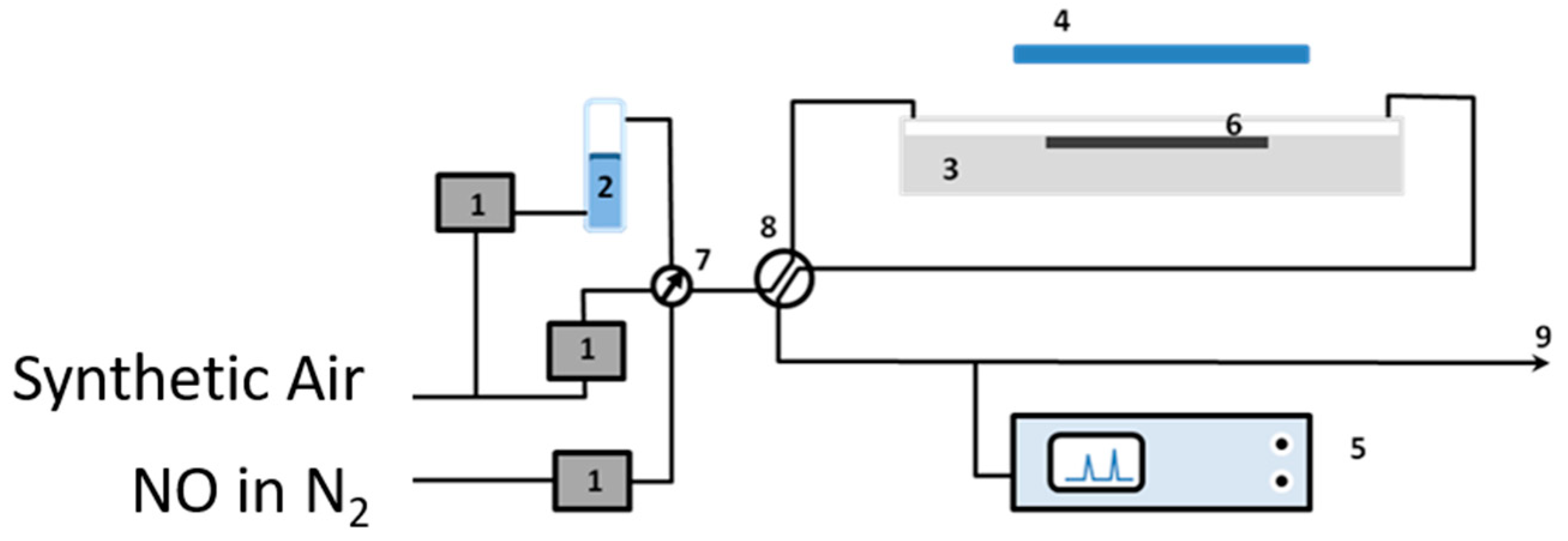
The removal of nitrogen oxides (NOx), as examples of air pollutants, using the obtained quartz sand modified with the photocatalyst was tested to check their efficiency in purification of the polluted air [23]. Figure 1 illustrates the air-purification test set-up which was established for this purpose. The set-up consists of the following (see Figure 1): gas suppliers; i.e., synthetic air and NO in nitrogen (BOC, Guildford, UK), gas flow controllers (Bronkhorst, Newmarket Suffolk, UK) (1), a humidity supplier unit (2), a photocatalytic reactor according to ISO standard design (ISO 22197-1) (3), a UV(A) irradiation source (4), and a NOx analyzer (5). The gas supplies were NO (100 ppm) in N2 and synthetic air (BOC, UK). The required concentration (1000 ppbv), flow rates (5 × 10⁻⁵ m3·s−1), and humidity (ca. 40%, confirmed by a Rotronic hygropalm) were achieved by controlling the flow of each gas by the gas flow controllers (1). The photoreactor was constructed from PMMA (Poly(methyl methacrylate)), covered with borosilicate glass, and was positioned below the output from an SS0.5 kW, 500 W fully reflective solar simulator equipped with a 1.5 AM filter (Sciencetech, London, Ontario, Canada). The irradiation was adjusted to ensure that the test sample (6) received a light intensity of 10 Wm−2 at λ < 420 nm. The light intensity was measured using a broadband thermopile detector (Gentec-EO-XLP12-3S-H2-D0) located exactly where the test sample should be placed. A Thermo Scientific Model 42i-HL High Level NO-NO2-NOx Analyzer (Air Monitors Ltd., Gloucestershire, UK) was used to monitor the concentrations of NO, NO2, and total NOx in the outlet gas flow. Aggregate exposed mortars were prepared by supporting 10 g of bare or TiO2-modified quartz sand on the top of mortars (with top surface area of 64 cm2 and thickness of 15 mm) in order to examine their efficiencies in NOx removal. For comparison, a reference sample was prepared according to the conventional mixing method (CMM) in which TiO2 was first mixed with cement at a 10 wt % ratio. Once prepared, a 2 mm thick layer of the mortar mixture was applied to the top of the pre-made mortar similar to those used to prepare the aggregate exposed mortars.
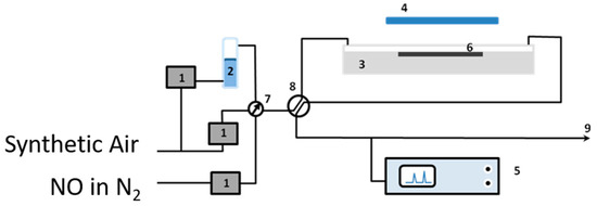
Figure 1.
The photocatalytic testing apparatus: (1) mass flow controllers, (2) humidity supplier, (3) photocatalytic reactor, (4) UV(A) irradiation source, (5) NOx analyzer, (6) test sample, (7) and (8) valves, and (9) gas stream outlet.
3. Results and Discussion
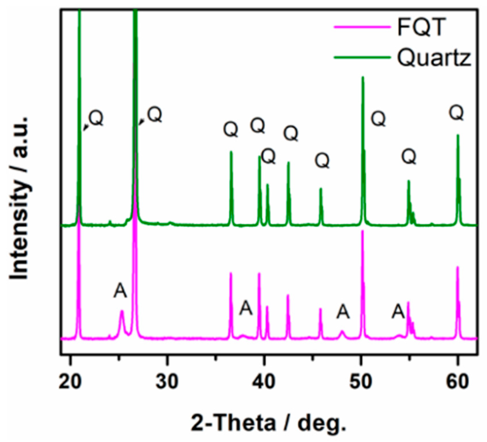
XRD patterns of uncoated quartz sand (Q) and the prepared TiO2–SiO2–Quartz composite (FQT) are shown in Figure 2. The appearance of a clear XRD pattern for anatase TiO2 in FQT sample confirms the successful support of TiO2 on the quartz in FQT.
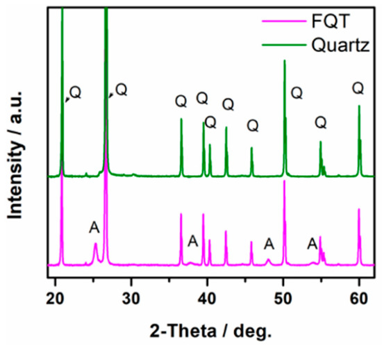
Figure 2.
XRD patterns of bare quartz and TiO2–SiO2–Quartz composite (FQT), Q and A refer to quartz and anatase patterns, respectively.
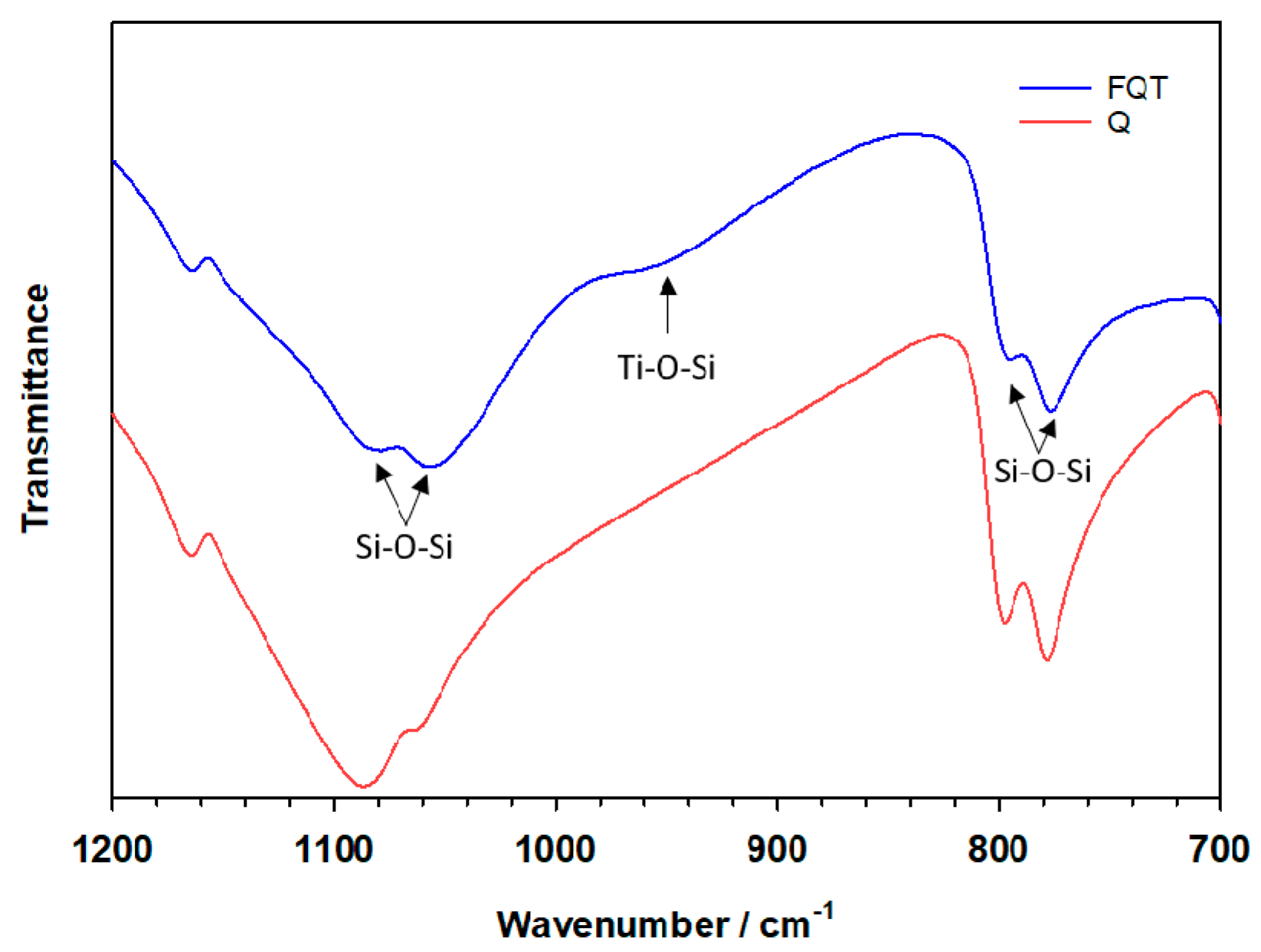
Evidence for the formation of a chemical bond between the TiO2 and SiO2 binding layers can clearly be observed from the FTIR spectrum in the range between 900–960 cm−1 (Figure 3), the absorption being assigned to the stretching vibrational mode of the Ti–O–Si bond. No similar absorption peak due to this mode was observed for SiO2 in the bare Q sample.
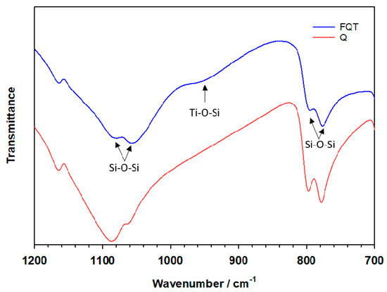
Figure 3.
FTIR spectra of bare quartz (Q) and the TiO2–SiO2–Quartz composite (FQT).
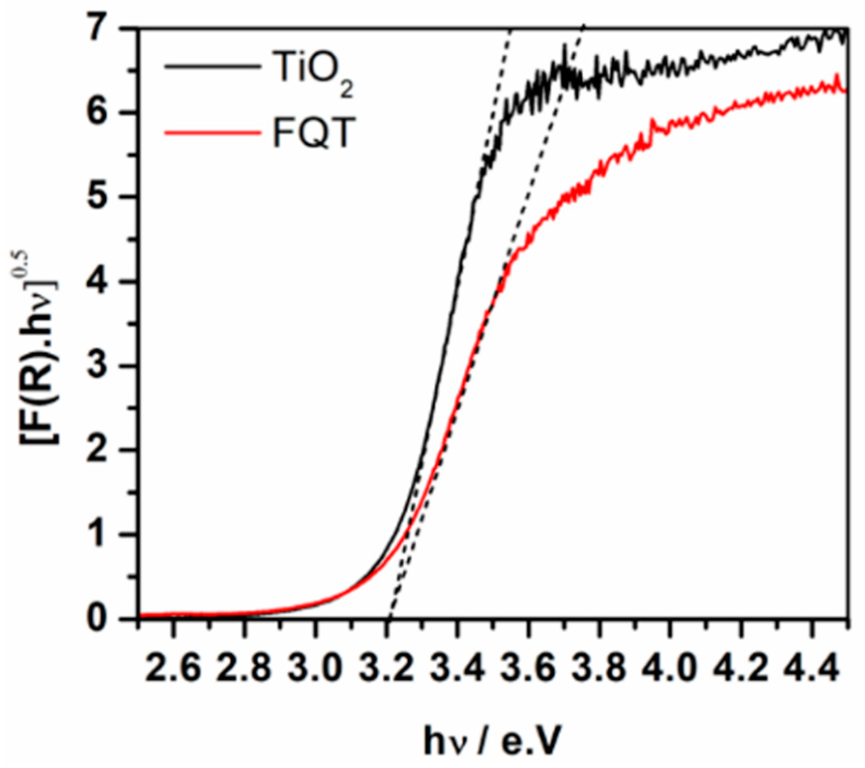
Figure 4 shows the diffuse reflectance UV-vis absorption spectra of free TiO2 and FQT composite samples. Considering TiO2 as an indirect semiconductor, the modified Kubelka–Munk function [F(R∞)hν]1/2 was plotted as a function of the incident photon energy which allowed the determination of the photocatalyst’s band gap. The spectra are additional evidence for the presence of TiO2 in the FQT sample and show that the loading of TiO2, via the herein employed method, on the surface of quartz through a SiO2 binding layer has negligible effect on its band gap.
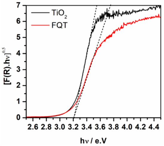
Figure 4.
UV-vis absorption spectra presented as the modified Kubelka–Munk function of free TiO2 and TiO2–SiO2–Quartz composite (FQT).
The amounts of TiO2 loaded on the surface of Q, as recorded by XRF analyses, are summarized in Table 1. As can be seen from this table, the actual amount of TiO2 loaded is lower than the calculated values for all the prepared samples, meaning that some loss of TiO2 occurred during the preparation procedure. However, the lower the loaded amount the lower the TiO2 loss. This indicates a limitation of the modifying layer thickness over which all the extra added amount of TiO2-binder is lost.

Table 1.
Calculated and analyzed loaded amount of TiO2 on quartz via silica gel binder.
The level of coverage of the support (Q) with TiO2 was examined using the SEM-EDS technique. Figure 5 compares the SEM-EDS of bare quartz coated with a silicate layer derived from TEOS in which commercial TiO2 (PC105) is dispersed. The effectiveness of a silicate-based layer on quartz (FQT) for the efficient support of TiO2 can be clearly seen from these SEM images. Very good coverage of TiO2 over the sample is achieved as a result of coating a silicate-based film over the quartz substrate.
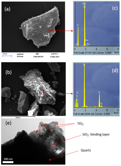
Figure 5.
SEM images for (a) uncoated quartz and (b) TiO2 (commercial PC105) immobilized on quartz via a SiO2 binder formed from tetraethyl orthosilicate (TEOS). EDS of these samples are presented in (c,d), and the TEM image for the same samples in (e).
Although a few areas might be clear of silicate coating, Figure 5 shows that the silicate layer has generally been immobilized nicely on the grains. Consequently, in this case, TiO2, associated with the silicate-based gel phase, is also similarly distributed and is not bonded directly to the quartz surface. This is consistent with the TEM image in Figure 5e. Comparing the EDS analyses (Figure 5c,d) indicates the spreading of TiO2 with the silicate layer.
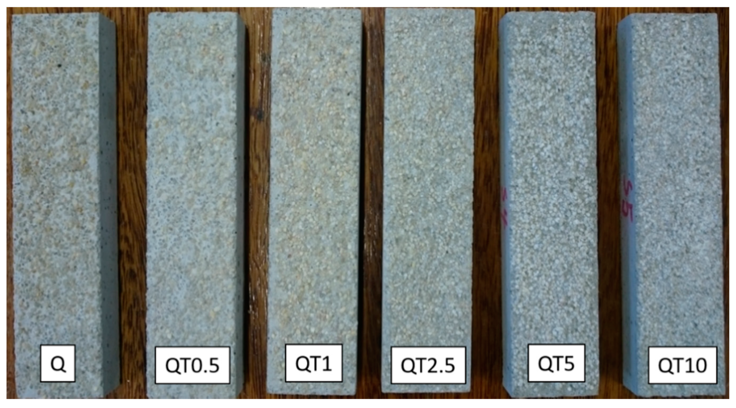
In order to examine the effectiveness of the obtained modified quartz sand samples for the removal of nitrogen oxides from polluted air, aggregate exposed mortars (with top surface areas of 64 cm2) were prepared, on top of which 10 g of bare or TiO2-modified quartz sand were supported. An image of the obtained mortars is presented in Figure 6 which shows a clear change in the color of the quartz sand to a whiter one by increasing the amounts of loaded TiO2.
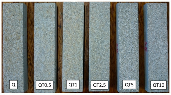
Figure 6.
Images of the prepared aggregate exposed mortars. On the top of each sample, 10 g of bare (Q) or TiO2-modified quartz sand (QTx) were supported.
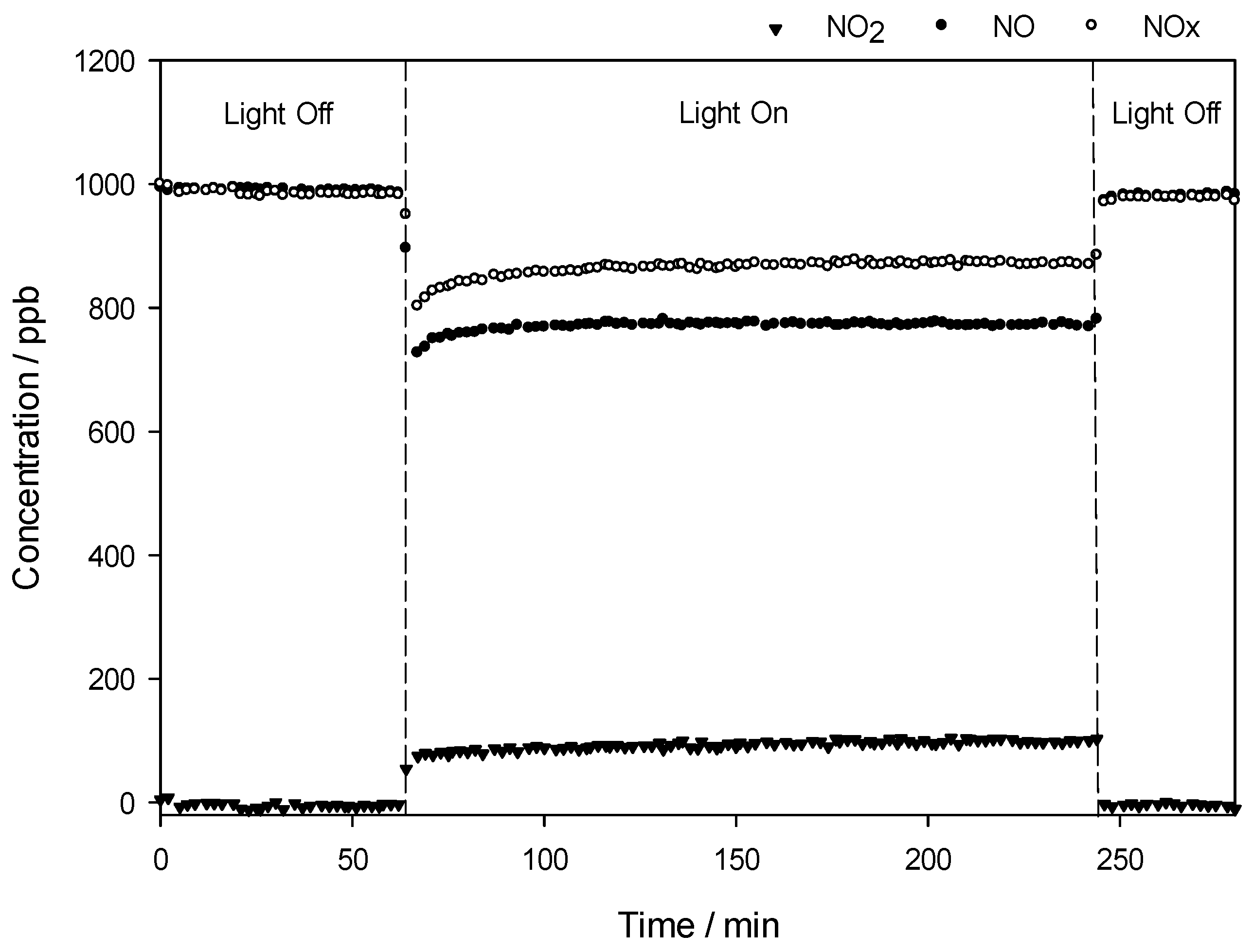
Figure 7 shows an example of the changes in the concentrations of nitrogen oxides, i.e., NO, NOx, and NO2, in the gas stream flows over the QT10 sample in the dark and under irradiation. The concentration of NO is constant at ca. 1000 ppb as long as the light is off. When the light is switched on, the initial NO concentration drops with a simultaneous increase in NO2 concentration, as NO2 is one of the NO oxidation products. Consequently, the concentration of NOx, which reflects the total oxidation of NO to HNO3, is reduced during the illumination time.

Figure 7.
Changes in the concentrations of nitrogen oxides, i.e., NO, NO2, and NOx, as a function of time in the presence of the QT10 sample.
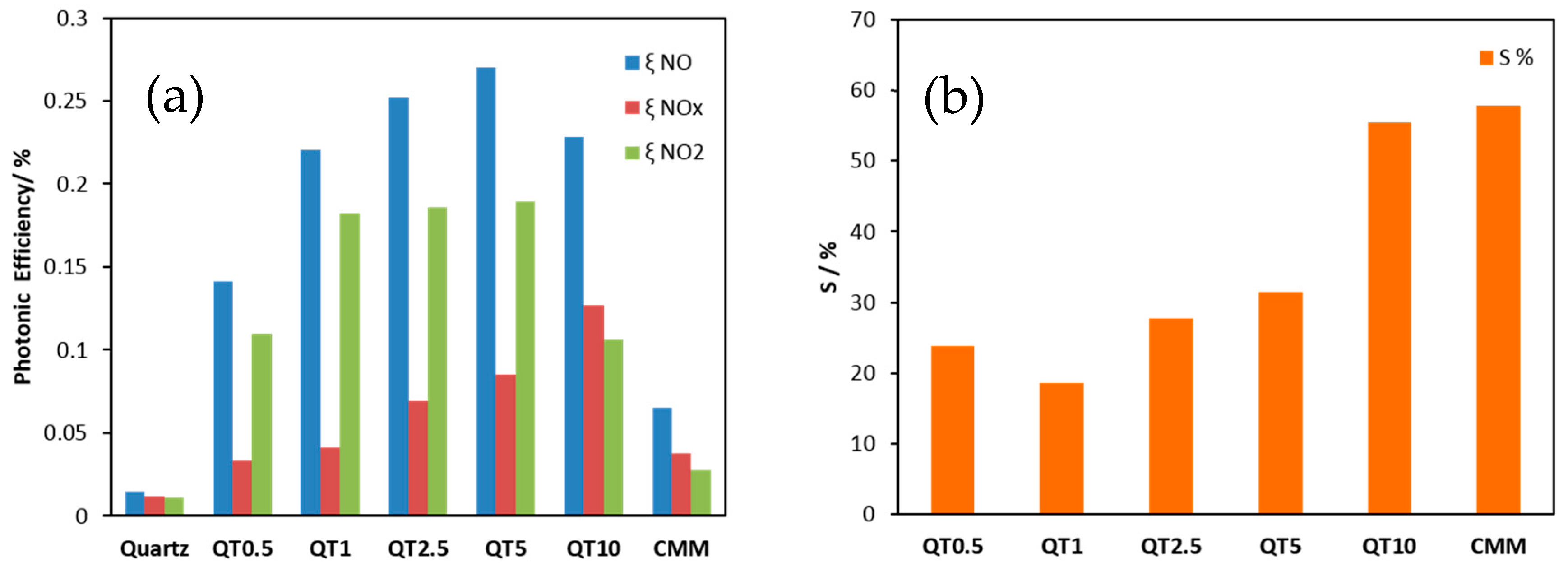
The activities of the obtained samples for De-NOx remediation were determined by measuring the photonic efficiencies (ξ), which is defined as the ratio of the reaction rate (NO and NOx removal as well as NO2 formation) and the incident photon flux [24]. Equation (1) was used to calculate ξ [25], where is the volumetric flow rate, cd the concentration of each of the nitrogen oxide gases recorded under dark conditions, ci the concentration of the same gases recorded under illumination, p the pressure, NA the Avogadro constant, h the Plank constant, c the speed of light, I the incident irradiation intensity, λ the employed wavelength assuming monochromatic light (365 nm), A the irradiated area, R the gas constant, and T the absolute temperature. The obtained results are illustrated in Figure 8a. The results of nitrate selectivity, which was calculated according to Equation (2) employing the obtained ξ NO and ξ NO2, both measured on the same sample, are shown in Figure 8b.
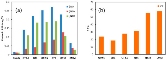
Figure 8.
Photonic efficiencies of the aggregate exposed mortars prepared from bare quartz or TiO2-modified quartz for NO and NOx removal and for NO2 formation (a), and nitrate selectivity recorded for the same samples (b).
As can be seen from Figure 8a, the De-NOx performance (0.14–0.23% ξ NO) is clearly enhanced by supporting the photocatalyst on quartz sand when compared to its performance (0.06% ξ NO) when mixed with cement (CMM). This means that supporting TiO2 on the quartz surface via a silica gel binder ensures a much higher effective surface area which is translated into higher photocatalytic efficiency. It is worth noting that the herein recorded photonic efficiency for NO oxidation measured for TiO2 supported on quartz (the QT5 sample for example) is about 58% of that reported in literature for the highly active bare anatase TiO2 (Hombikat UV100) [25]. Bearing in mind that QT5 had only 2.9% of the TiO2 loaded, a significantly efficient utilization of the valuable photocatalyst is consequently achieved by supported systems. It is also worth mentioning that although the De-NOx performance improves by increasing the amount of photocatalyst loaded from QT1 to QT5, QT1 might be preferred from an economical viewpoint as this sample showed a ξ NO of more than 80% of that measured for QT5 although QT1 had ca. five times less TiO2 compared to QT5. On the other hand, nitrate selectivity (Figure 8b) was also enhanced by increasing the amount of photocatalyst loaded but did not exceed that of CMM. The high selectivity is surely a valuable opportunity and improved by a higher loading amount. This observation can be explained by the fact that the porous silica gel coating presents a support for TiO2 both as TiO2 bonded to the silica gel pore walls (which usually negatively affects the selectivity) but also as TiO2 trapped in the pores. This non-bonded TiO2 offers increased activity and selectivity. Factors which control nitrate selectivity appear to be complex. Relevant variables include TiO2 polymorphism, defect state, availability of water, etc., but the role of substrate binding must also be considered.
4. Conclusions
TiO2 has been successfully loaded on the surface of aggregate, with quartz used as an example, utilizing a silicate-based binder. Aggregate exposed mortars with these photocatalytically active aggregates on the surface have shown an excellent performance at the photocatalytic removal of NO from polluted air. The herein developed aggregate exposed mortars have shown up to ca. four times higher efficiency for NO removal compared with the sample prepared according to the conventional mixing method (CMM). Thus, the herein prepared supported TiO2 aggregates offer much greater utilization efficiency for the valuable photocatalyst and thus correspond to a considerably lower cost of use in photocatalytic concrete.
Author Contributions
Conceptualization, A.H. and D.E.M.; methodology, A.H. and L.Y.; validation, A.H., L.Y. and D.E.M.; formal analysis, A.H.; investigation, A.H.; resources, D.E.M. and F.W.; data curation, A.H.; writing—original draft preparation, A.H.; writing—review and editing, D.E.M., A.E. and Y.A.; visualization, A.H., D.E.M. and A.E.; supervision, D.E.M. and F.W.; project administration, D.E.M.; funding acquisition, D.E.M. and F.W.
Funding
This research was funded by the UK Engineering and Physical Sciences Research Council (Grant Ref: EP/M003299/1) and the Natural Science Foundation of China (No. 51461135005) International Joint Research Project (EPSRC-NSFC). The APC was funded by (GORD).
Acknowledgments
The authors gratefully acknowledge funding from the UK Engineering and Physical Sciences Research Council (Grant Ref: EP/M003299/1) and the Natural Science Foundation of China (No. 51461135005) International Joint Research Project (EPSRC-NSFC). L. Zheng and M. R. Jones from the Division of Civil Engineering, University of Dundee, Dundee, UK are gratefully acknowledged for the preparation of the mortars.
Conflicts of Interest
The authors declare no conflict of interest.
References
- West, J.J.; Cohen, A.; Dentener, F.; Brunekreef, B.; Zhu, T.; Armstrong, B.; Bell, M.L.; Brauer, M.; Carmichael, G.; Costa, D.L.; et al. What We Breathe Impacts Our Health: Improving Understanding of the Link between Air Pollution and Health. Environ. Sci. Technol. 2016, 50, 4895–4904. [Google Scholar] [CrossRef] [PubMed]
- Walton, H.; Dajnak, D.; Beevers, S.; Williams, M.; Watkiss, P.; Hunt, A. Understanding the Health Impacts of Air Pollution in London. King’s College London, 15 July 2015. [Google Scholar]
- WHO. Ambient (Outdoor) Air Quality and Health; WHO: Geneva, Switzerland, 2014. [Google Scholar]
- Abdul-Wahab, S.A.; Chin Fah En, S.; Elkamel, A.; Ahmadi, L.; Yetilmezsoy, K. A review of standards and guidelines set by international bodies for the parameters of indoor air quality. Atmos. Pollut. Res. 2015, 6, 751–757. [Google Scholar] [CrossRef]
- Serpone, N. Heterogeneous Photocatalysis and Prospects of TiO2-Based Photocatalytic DeNOxing the Atmospheric Environment. Catalysts 2018, 8, 553. [Google Scholar] [CrossRef]
- Engel, A.; Große, J.; Dillert, R.; Bahnemann, D.W. The Influence of Irradiance and Humidity on the Photocatalytic Conversion of Nitrogen(II) Oxide. J. Adv. Oxid. Technol. 2015. [Google Scholar] [CrossRef]
- Devahasdin, S.; Fan, C.; Li, K.; Chen, D.H. TiO2photocatalytic oxidation of nitric oxide: Transient behavior and reaction kinetics. J. Photochem. Photobiol. A Chem. 2003, 156, 161–170. [Google Scholar] [CrossRef]
- Maggos, T.; Bartzis, J.G.; Liakou, M.; Gobin, C. Photocatalytic degradation of NOx gases using TiO2-containing paint: A real scale study. J. Hazard. Mater. 2007, 146, 668–673. [Google Scholar] [CrossRef] [PubMed]
- Hüsken, G.; Hunger, M.; Brouwers, H.J.H. Experimental study of photocatalytic concrete products for air purification. Build. Environ. 2009, 44, 2463–2474. [Google Scholar] [CrossRef]
- Ballari, M.M.; Brouwers, H.J.H. Full scale demonstration of air-purifying pavement. J. Hazard. Mater. 2013, 254–255, 406–414. [Google Scholar] [CrossRef] [PubMed]
- Cassar, L. Photocatalysis of cementitious materials: Clean buildings and clean air. MRS Bull. 2004. [CrossRef]
- Folli, A.; Pochard, I.; Nonat, A.; Jakobsen, U.H.; Shepherd, A.M.; Macphee, D.E. Engineering photocatalytic Cements: Understanding TiO2surface chemistry to control and modulate photocatalytic performances. J. Am. Ceram. Soc. 2010, 939, 3360–3369. [Google Scholar] [CrossRef]
- MacPhee, D.E.; Folli, A. Photocatalytic concretes—The interface between photocatalysis and cement chemistry. Cem. Concr. Res. 2016, 85, 48–54. [Google Scholar] [CrossRef]
- Folli, A.; Pade, C.; Hansen, T.B.; De Marco, T.; MacPhee, D.E. TiO2 photocatalysis in cementitious systems: Insights into self-cleaning and depollution chemistry. Cem. Concr. Res. 2012, 42, 539–548. [Google Scholar] [CrossRef]
- Zhang, R.; Cheng, X.; Hou, P.; Ye, Z. Influences of nano-TiO2 on the properties of cement-based materials: Hydration and drying shrinkage. Constr. Build. Mater. 2015, 81, 35–41. [Google Scholar] [CrossRef]
- Yang, L.; Wang, F.; Hakki, A.; Macphee, D.E.; Liu, P.; Hu, S. The influence of zeolites fly ash bead/TiO2 composite material surface morphologies on their adsorption and photocatalytic performance. Appl. Surf. Sci. 2017, 392, 687–696. [Google Scholar] [CrossRef]
- Hakki, A.; Yang, L.; Wang, F.; Macphee, D.E. The Effect of Interfacial Chemical Bonding in TiO2 Composites on Their Photocatalytic NOx Abatement Performance. J. Vis. Exp. 2017, 4. [Google Scholar] [CrossRef]
- Yang, L.; Hakki, A.; Wang, F.; Macphee, D.E. Different Roles of Water in Photocatalytic DeNOx Mechanisms on TiO2: Basis for Engineering Nitrate Selectivity? ACS Appl. Mater. Interfaces 2017, 9, 17034–17041. [Google Scholar] [CrossRef]
- Fateh, R.; Dillert, R.; Bahnemann, D. Preparation and characterization of transparent hydrophilic photocatalytic TiO2/SiO2 thin films on polycarbonate. Langmuir 2013, 29, 3730–3739. [Google Scholar] [CrossRef]
- Hanus, M.J.; Harris, A.T. Nanotechnology innovations for the construction industry. Prog. Mater. Sci. 2013, 58, 1056–1102. [Google Scholar] [CrossRef]
- Lucas, S.S.; Ferreira, V.M.; De Aguiar, J.L.B. Incorporation of titanium dioxide nanoparticles in mortars—Influence of microstructure in the hardened state properties and photocatalytic activity. Cem. Concr. Res. 2013, 43, 112–120. [Google Scholar] [CrossRef]
- Ballari, M.M.; Hunger, M.; Hüsken, G.; Brouwers, H.J.H. NOx photocatalytic degradation employing concrete pavement containing titanium dioxide. Appl. Catal. B Environ. 2010, 95, 245–254. [Google Scholar] [CrossRef]
- ISO. ISO 22197-1: Fine Ceramics (Advanced Ceramics, Advanced Technical Ceramics)—Test Method for air-purification Performance of Semiconducting Photocatalytic Materials—Part 1: Removal of Nitric Oxide; ISO: Geneva, Switzerland, 2007. [Google Scholar]
- Kisch, H.; Bahnemann, D. Best Practice in Photocatalysis: Comparing Rates or Apparent Quantum Yields? J. Phys. Chem. Lett. 2015, 6, 1907–1910. [Google Scholar] [CrossRef] [PubMed]
- Freitag, J.; Domínguez, A.; Niehaus, T.A.; Hülsewig, A.; Dillert, R.; Frauenheim, T.; Bahnemann, D.W. Nitrogen(II) oxide charge transfer complexes on TiO2: A new source for visible-light activity. J. Phys. Chem. C 2015, 119, 4488–4501. [Google Scholar] [CrossRef]

© 2019 by the authors. Licensee MDPI, Basel, Switzerland. This article is an open access article distributed under the terms and conditions of the Creative Commons Attribution (CC BY) license (http://creativecommons.org/licenses/by/4.0/).