A Simple Approach for the Design of Ductile Earthquake-Resisting Frame Structures Counting for P-Delta Effect


Abstract
:1. Introduction
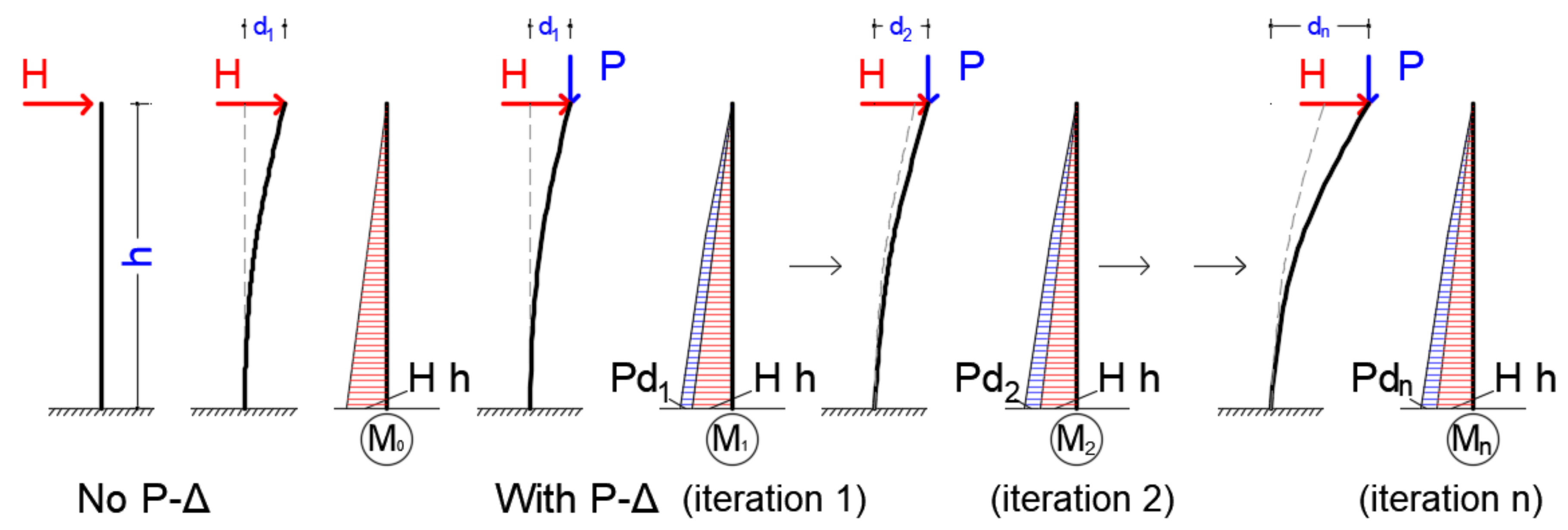
2. The P-Delta Inelastic Analysis
2.1. The SDOF System
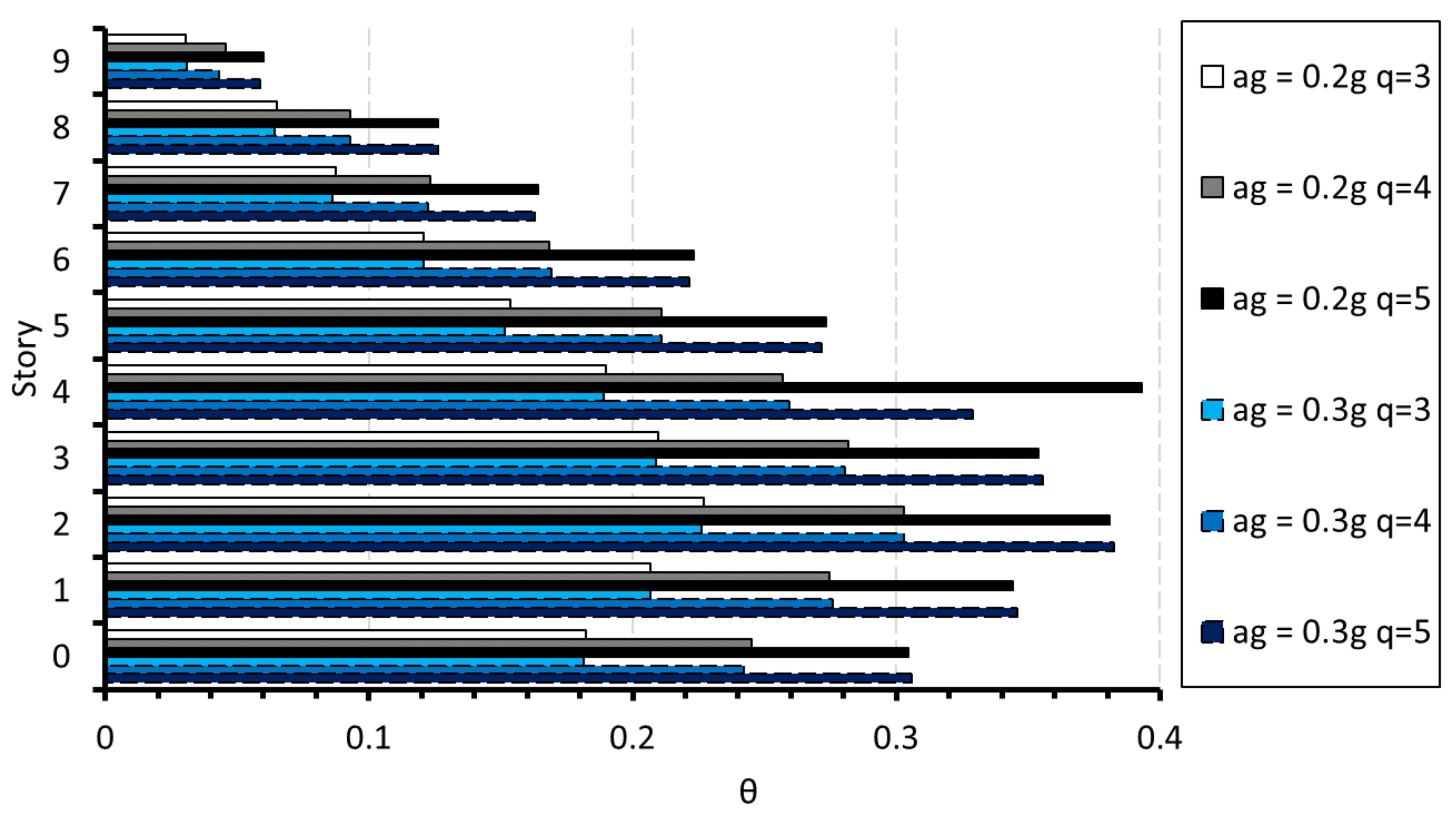
- is the interstory drift sensitivity coefficient or the stability coefficient;
- is the total gravity load above the considered story in the seismic design combination;
- is the design interstory drift, evaluated as the difference of the average lateral displacements at the top and bottom of the story under consideration;
- is the total seismic story shear;
- and is the story height.
- is the displacement of a point of the structural system induced by the seismic design actions;
- is the displacement behavior factor, assumed equal to q unless otherwise specified;
- is the displacement of the same point of the structural system, as determined by a linear analysis based on the design response spectrum.
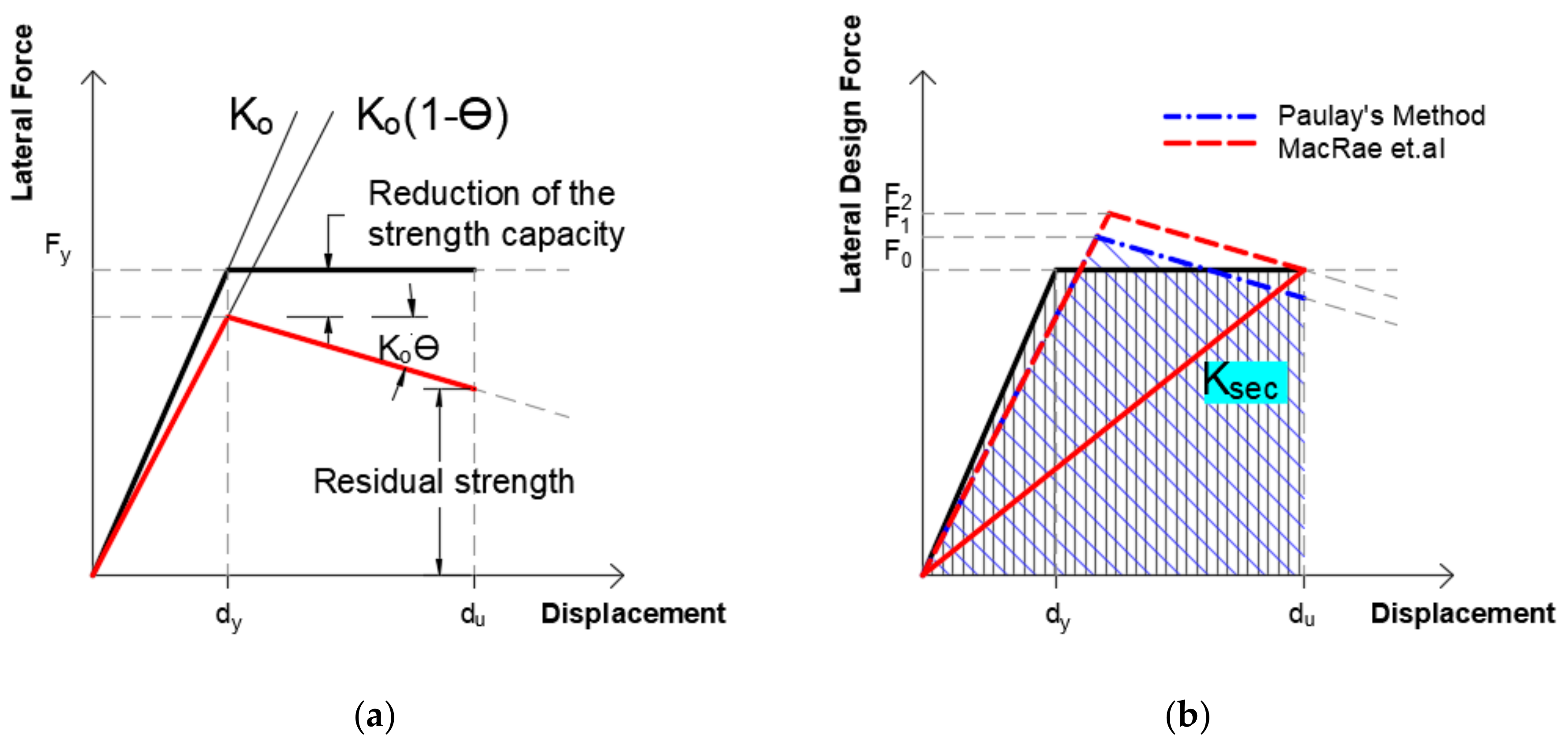
2.2. The P-Delta Effect and the Behavior Factor (q)
- (a)
- Apply simultaneously the lateral and vertical loads and implement the stiffness matrix according to Equation (2).
- (b)
- Apply the vertical loads in the system and use the resulting stiffness matrix in a second step where the lateral loads are then applied. This approach is the key to the here-proposed method.
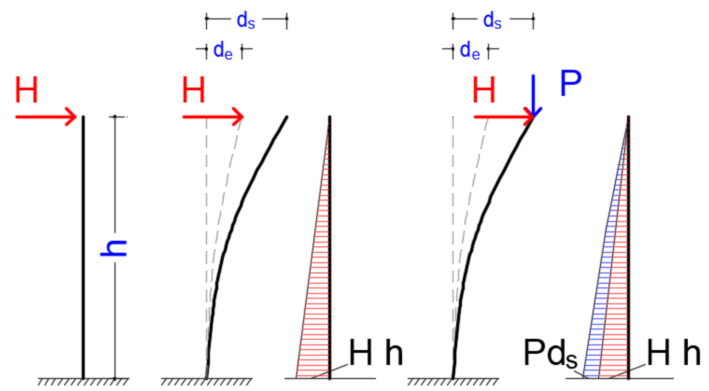
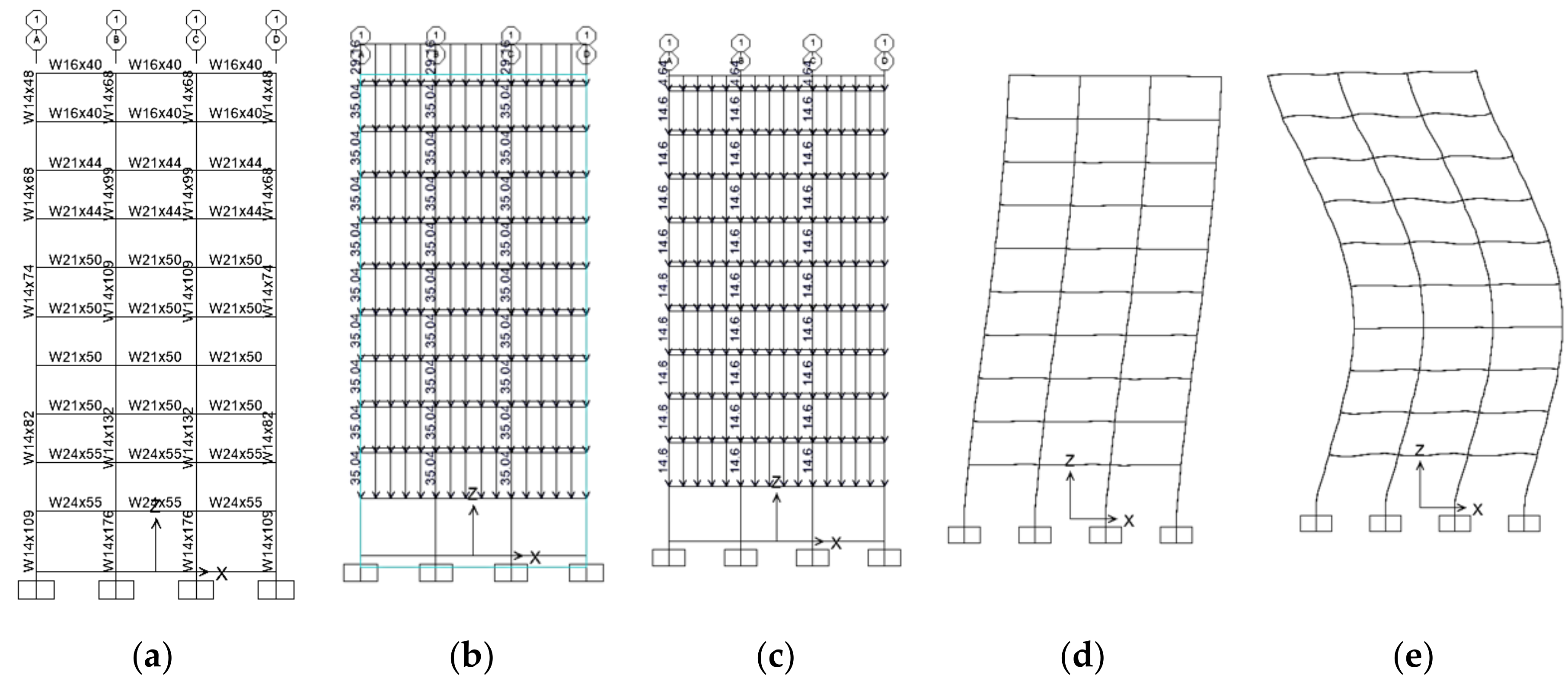
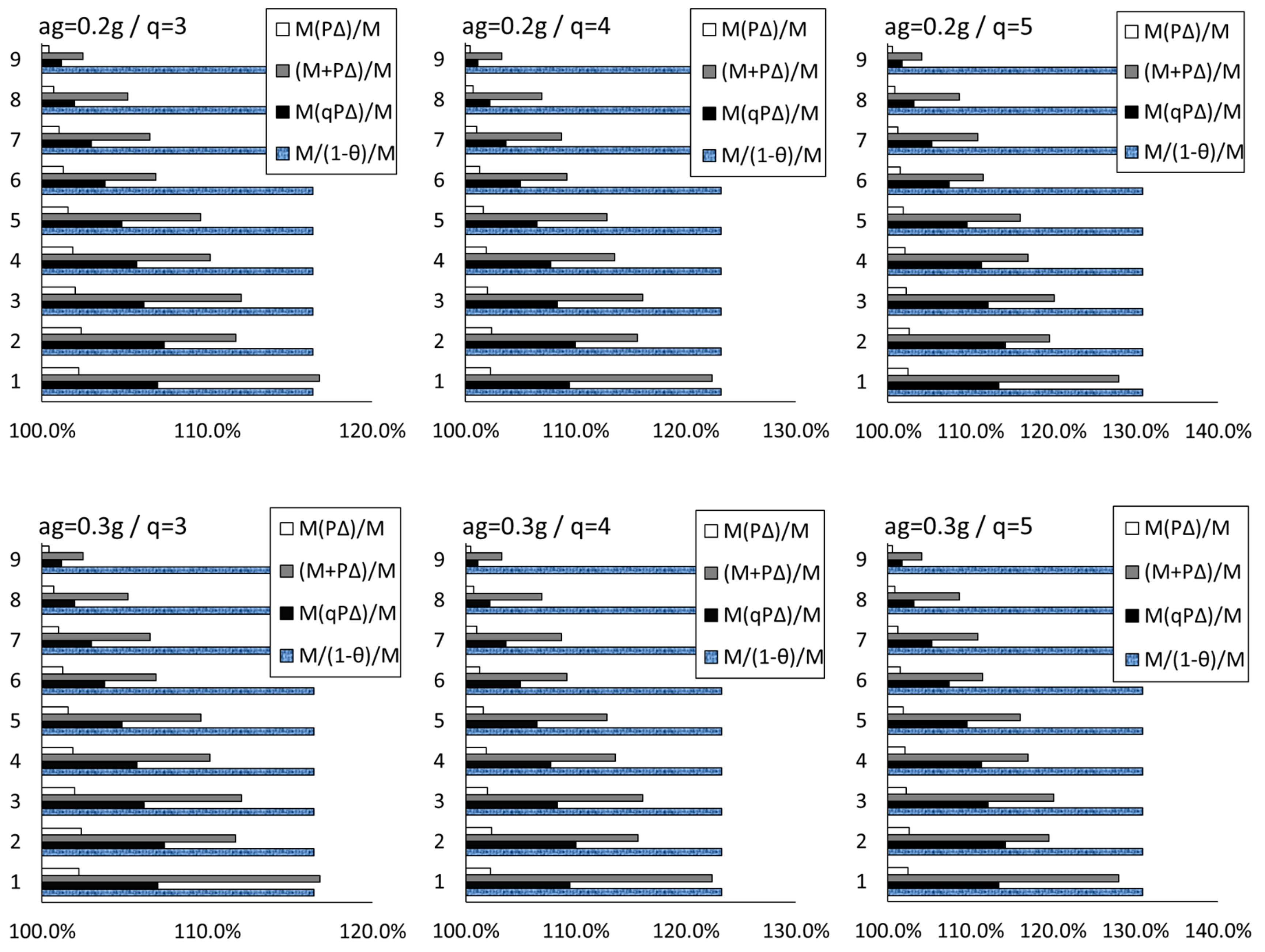
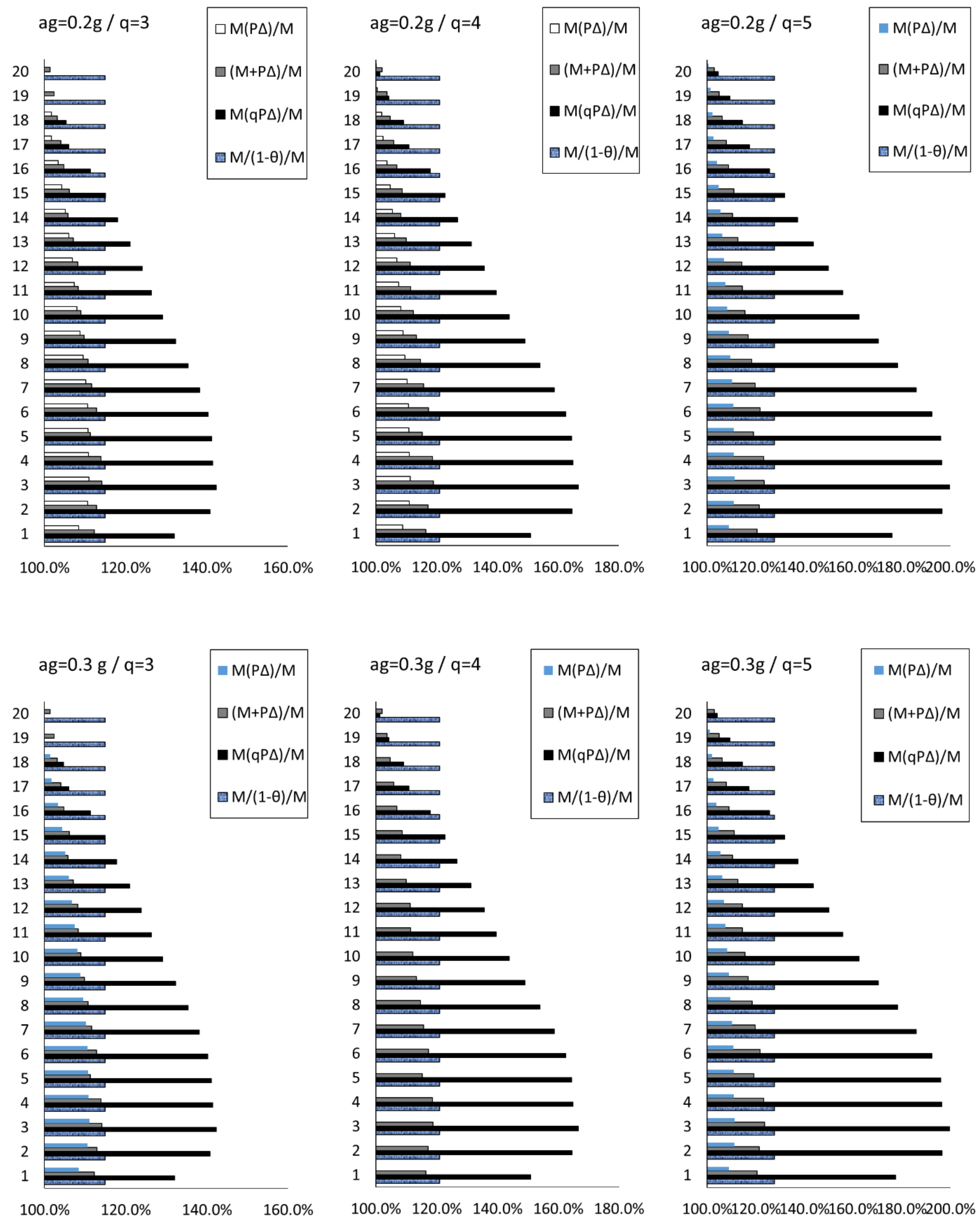
2.3. The P-Delta Effect on MDOF Systems
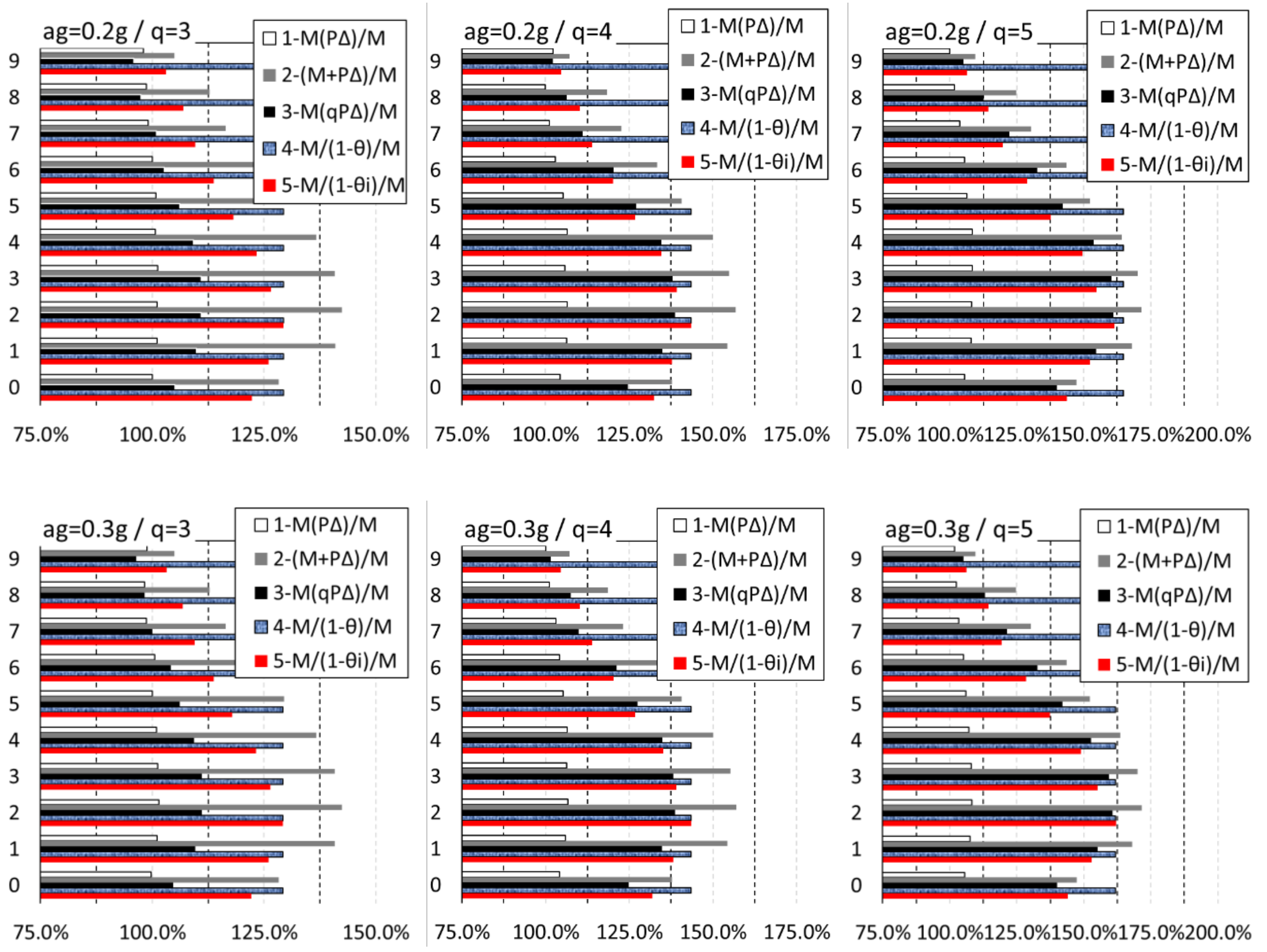
- A simple response spectrum analysis is performed including the geometrical nonlinearities derived from the implementation of a - analysis.
- The deformations derived from simple response spectrum analysis are multiplied with the normal forces and then manually added to the moments obtained from the RS analysis. No moment redistribution is applied here.
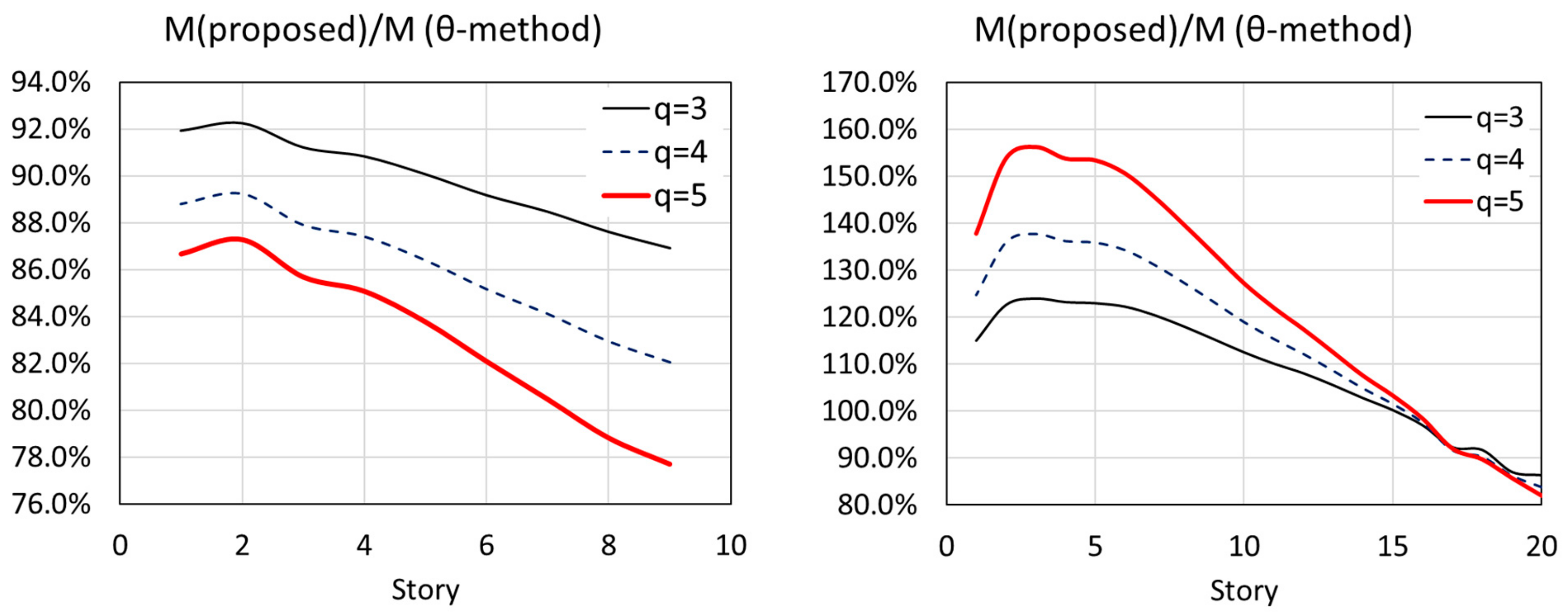
- A simple response spectrum analysis is performed including the nonlinearities derived from - analysis assuming that the structure behaves inelastically, according to the approach presented in Section 2.2 for the SDOF systems. The vertical load in the - forming stiffness matrix process is multiplied with the q factor.
- The results obtained from the response spectrum analysis are amplified by the factor, assuming the maximum value is obtained for the instability coefficients at each story, as is recommended in [29].
- The results obtained from the response spectrum analysis are amplified by the factor, estimated to each story. At present, there is no reference to implement this approach, thenceforth the meaning is only to provide a full picture to the expected amplification effect from the - analysis, comparable here with the physics approach of the second method.
3. The Three-Step Procedure
- Step 1. The inputs for the structural analysis are selected: the peak ground acceleration (PGA) and the behavior factor (q). The selected behavior factor should reflect also the expected ductility of the structure, thenceforth it should neither underestimate nor overestimate such value in order to obtain a realistic design.
- Step 2. Perform a nonlinear analysis considering the geometrical nonlinearity. The vertical forces in this analysis are magnified with the behavior factor in order to consider the amplification of the P-Δ effects as a result of the inelastic displacements. This analysis will be used as a starting point for the application of successive analysis.
- Step 3. Perform linear analysis, Response Spectrum analysis, or equivalent seismic analysis using the stiffness matrix of the previous analysis for the determination of the seismic actions. Many software programs, like SAP2000 [30] or other commercial packages [31,32,33], allow running an analysis using the stiffness matrix of a previous analysis. Hence such a requirement is mandatory for the implementation of the present approach.
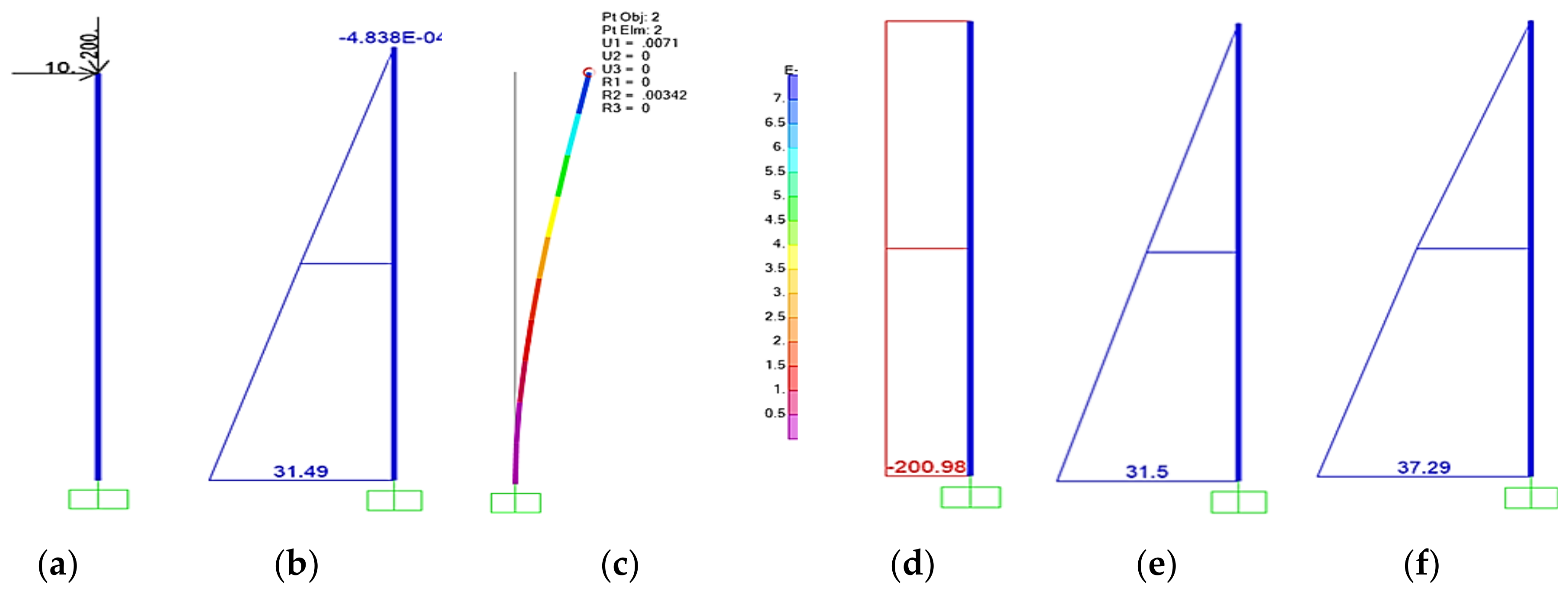
4. Case Studies
5. Conclusions
Author Contributions
Funding
Conflicts of Interest
References
- Fema-356 Prestandard and Commentary for the Seismic Rehabilitation of Buildings; Federal Emergency Management Agency: Washington, DC, USA, 2000.
- Fardis, M.N. Seismic Design, Assessment and Retrofitting of Concrete Buildings; Geotechnical, Geological, and Earthquake Engineering; Springer: Dordrecht, The Netherlands, 2009; Volume 8, ISBN 978-1-4020-9841-3. [Google Scholar]
- DPCM. Linee Guida per la Valutazione e la Riduzione del Rischio Sismico del Patrimonio Culturale con Riferimento alle Norme tecniche per le Costruzioni di cui al Decreto del M.I.T del (2008); Decreto del Presidente del Consiglio dei Ministry: Rome, Italy, 2011.
- Grünthal, G. European Macroseismic Scale 1998; European Center of Geodynamics and Seismilogy: Walferdange, Luxembourg, 1998; Volume 15, ISBN 2879770084. [Google Scholar]
- Gioncu, V.; Mazzolani, F. Ductility of Seismic-Resistant Steel Structures, 1st ed.; CRC Press: Boca Raton, FL, USA, 2002; p. 720. [Google Scholar]
- Chopra, A.K. Dynamics of structures: Theory and Applications to Earthquake Engineering, 4th ed.; Prentice Hall: Upper Saddle River, NJ, USA, 2011; ISBN 013156174X. [Google Scholar]
- Dowrick, D.J. Earthquake Resistant Design and Risk Reduction; John Wiley & Sons, Inc.: Hoboken, NJ, USA, 2009; ISBN 9780470747025. [Google Scholar]
- Williamson, E.B. Evaluation of Damage and P -Δ Effects for Systems Under Earthquake Excitation. J. Struct. Eng. 2003, 129, 1036–1046. [Google Scholar] [CrossRef]
- Montgomery, C.J. Influence of P—Delta effects on seismic design. Can. J. Civ. Eng. 2010, 8, 31–43. [Google Scholar] [CrossRef]
- Fema P-58-1 Seismic Performance Assessment of Buildings—Methodology; Federal Emergency Management Agency: Washington, DC, USA, 2012; Volume 1.
- Gupta, A.; Krawinkler, H. Dynamic P-Delta Effects for Flexible Inelastic Steel Structures. J. Struct. Eng. 2002, 126, 145–154. [Google Scholar] [CrossRef]
- Pettinga, D.; Priestley, N. Accounting for P-Delta effects in structures when using direct displacement-based design. In Proceedings of the 14th World Conference Earthquake Engineering, Beijing, China, 12–17 October 2008; pp. 1–8. [Google Scholar]
- Lignos, D.G.; Putman, C.; Krawinkler, H. Application of simplified analysis procedures for performance-based earthquake evaluation of steel special moment frames. Earthq. Spectra 2015, 31, 1949–1968. [Google Scholar] [CrossRef]
- EC-8-P-1. Eurocode 8: Design of Structures for Earthquake Resistance—Part 1: General Rules, Seismic Actions and Rules for Buildings; European Commission: Brussels, Belgium, 2014. [Google Scholar]
- Kirsch, U. Reanalysis of Structures: A Unified Approach for Linear, Nonlinear, Static and Dynamic Systems; Springer: Dordrecht, The Netherlands, 2010; Volume 151, ISBN 9781402081972. [Google Scholar]
- Shehu, R. The P-Δ-Ductility Effect: Overview the Effect of the Second Order in the Ductil Structures. Eur. Sci. J. 2014, 3, 7881. [Google Scholar]
- MacRae, G.a. P-Δ Effects on Single-Degree-of-Freedom Structures in Earthquakes. Earthq. Spectra 1994, 10, 539. [Google Scholar] [CrossRef]
- Sucuoğlu, H.; Akkar, S.; Halûk, S.; Sinan, A. Basic Earthquake Engineering; Springer: Dordrecht, The Netherlands, 2014; ISBN 9783319010250. [Google Scholar]
- Ministero delle Infrastrutture e dei Trasporti Aggiornamento delle “Norme Tecniche per le Costruzioni”—NTC. Gazzetta Ufficiale 2018, 1–198.
- Priestley, M.J.N. Performance Based Seismic Design; Bulletin of the New Zealand Society for Earthquake Engineering: Wellington, New Zealand, 2000; pp. 325–346. [Google Scholar]
- Vamvatsikos, D.; Kazantzi, A.K.; Aschheim, M.A. Performance-Based Seismic Design: Avant-Garde and Code-Compatible Approaches. ASCE J. 2016, 2, 1–9. [Google Scholar] [CrossRef]
- Aschheim, M.; Montes, E.H. The representation of P-Δ effects using Yield Point Spectra. Eng. Struct. 2003, 25, 1387–1396. [Google Scholar] [CrossRef]
- Black, E.F. Use of stability coefficients for evaluating the P-δ effect in regular steel moment resisting frames. Eng. Struct. 2011, 33, 1205–1216. [Google Scholar] [CrossRef]
- Wilson, E.L. Three-Dimensional Static and Dynamic Analysis of Structures: A Physical Approach with Emphasis on Earthquake Engineering, 3rd ed.; Computers & Structures, Inc.: Berkeley, CA, USA, 2002; ISBN 0923907009. [Google Scholar]
- Paulay, T.; Priestley, M.J.N. Seismic Design of Reinforced Concrete and Masonry Buildings; Wiley & Sons: Hoboken, NJ, USA, 1992; ISBN 9780470172841. [Google Scholar]
- Fajfar, P. A Nonlinear Analysis Method for Performance-Based Seismic Design. Earthq. Spectra 2000, 16, 573–592. [Google Scholar] [CrossRef]
- Clough, R.W.; Penzien, J. Dynamic of Structures, 3rd ed.; McGraw-Hill: New York, NY, USA, 1993. [Google Scholar]
- Anderson, J.C.; Bertero, V.V. Uncertainties in Establishing Design Earthquakes. J. Struct. Eng. 2008, 113, 1709–1724. [Google Scholar] [CrossRef]
- FEMA 450 Nehrp Recommended Provisions for Seismic Regulations for New Buildings and Other Structures; Part 1; Federal Emergency Management Agency: Washington, DC, USA, 2003; p. 338.
- CSI. CSI Analysis Reference Manual; CSI: Walnut Creek, CA, USA, 2015. [Google Scholar]
- Simulia, D.S. Abaqus 6.14 Documentation; Vélizy-Villacoublay: Paris, France, 2014. [Google Scholar]
- Diana, F.E.A. Diana User’s Manual; Release 10.2; Diana Inc.: Delft, The Netherlands, 2017. [Google Scholar]
- ANSYS Inc. Element Reference for ANSYS Mechanical APDL; ANSYS Inc.: Canonsburg, PA, USA, 2012. [Google Scholar]
- Gupta, A.; Krawinkler, H. Seismic Demands for Performance Evaluation of Steel Moment Resisting Frame Structures; Stanford University: Stanford, CA, USA, 1999. [Google Scholar]
- Bernal, D. Instability of buildings during seismic response. Eng. Struct. 1998, 20, 496–502. [Google Scholar] [CrossRef]


| Structure | Period [s] | |
|---|---|---|
| Mode 1 (Present Study) | Range of Mode 1 From [29] | |
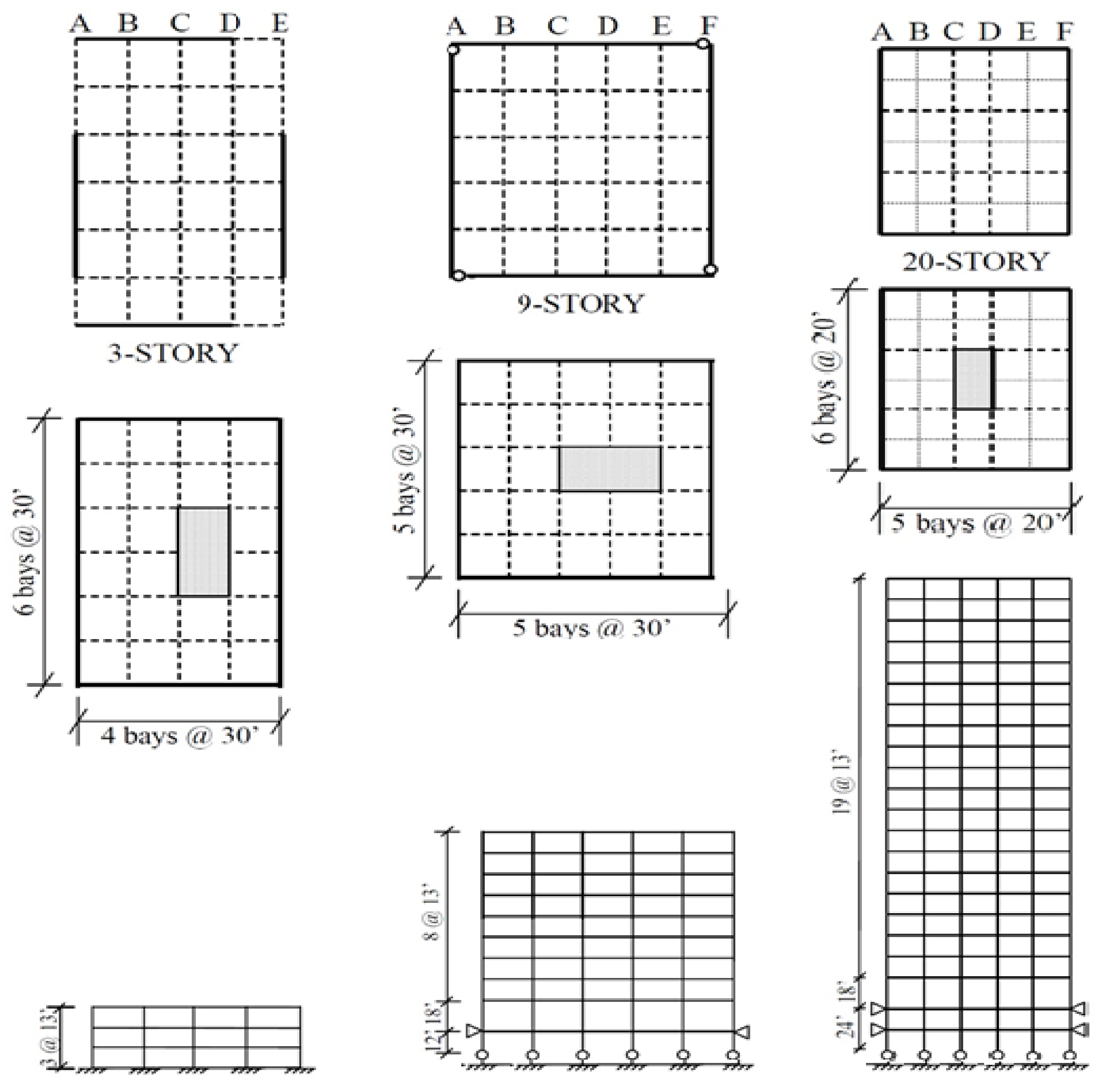
| LA 3-Story | 0.9 s | 0.85–1.03 s |
| LA 9-Story | 2.03 s | 1.97–2.34 s |
| LA 20-Story | 3.65 s | 3.45–3.98 s |
© 2019 by the authors. Licensee MDPI, Basel, Switzerland. This article is an open access article distributed under the terms and conditions of the Creative Commons Attribution (CC BY) license (http://creativecommons.org/licenses/by/4.0/).
Share and Cite
Shehu, R.; Angjeliu, G.; Bilgin, H. A Simple Approach for the Design of Ductile Earthquake-Resisting Frame Structures Counting for P-Delta Effect. Buildings 2019, 9, 216. https://doi.org/10.3390/buildings9100216
Shehu R, Angjeliu G, Bilgin H. A Simple Approach for the Design of Ductile Earthquake-Resisting Frame Structures Counting for P-Delta Effect. Buildings. 2019; 9(10):216. https://doi.org/10.3390/buildings9100216
Chicago/Turabian StyleShehu, Rafael, Grigor Angjeliu, and Huseyin Bilgin. 2019. "A Simple Approach for the Design of Ductile Earthquake-Resisting Frame Structures Counting for P-Delta Effect" Buildings 9, no. 10: 216. https://doi.org/10.3390/buildings9100216
APA StyleShehu, R., Angjeliu, G., & Bilgin, H. (2019). A Simple Approach for the Design of Ductile Earthquake-Resisting Frame Structures Counting for P-Delta Effect. Buildings, 9(10), 216. https://doi.org/10.3390/buildings9100216