
The Effects of Void on Natural Ventilation Performance in Multi-Storey Housing

Abstract
:1. Introduction
2. Method and Procedure
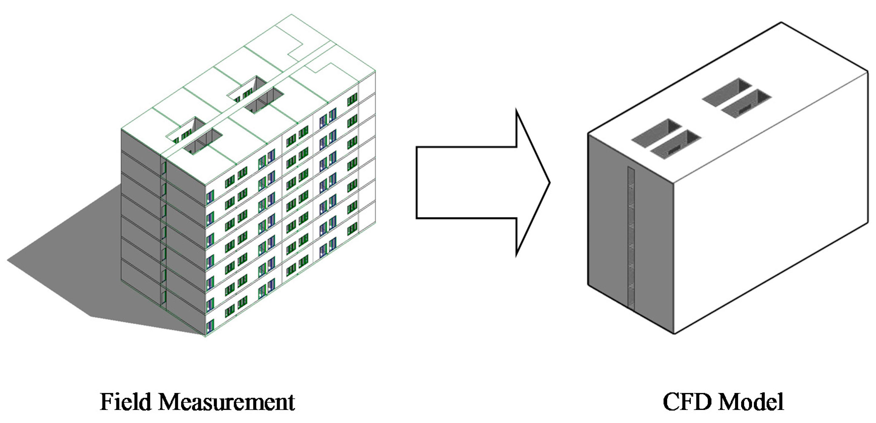
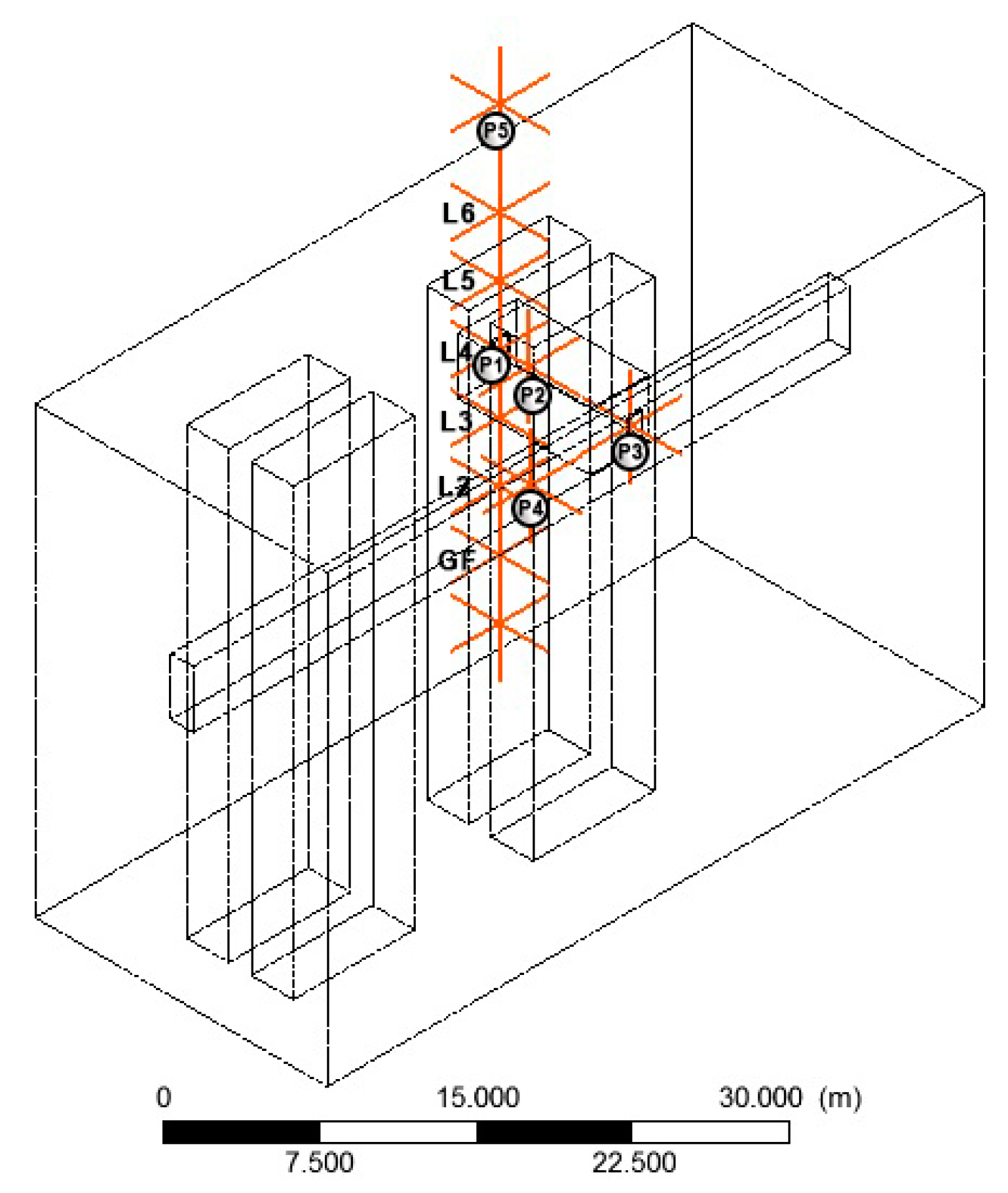
2.1. Field Measurement
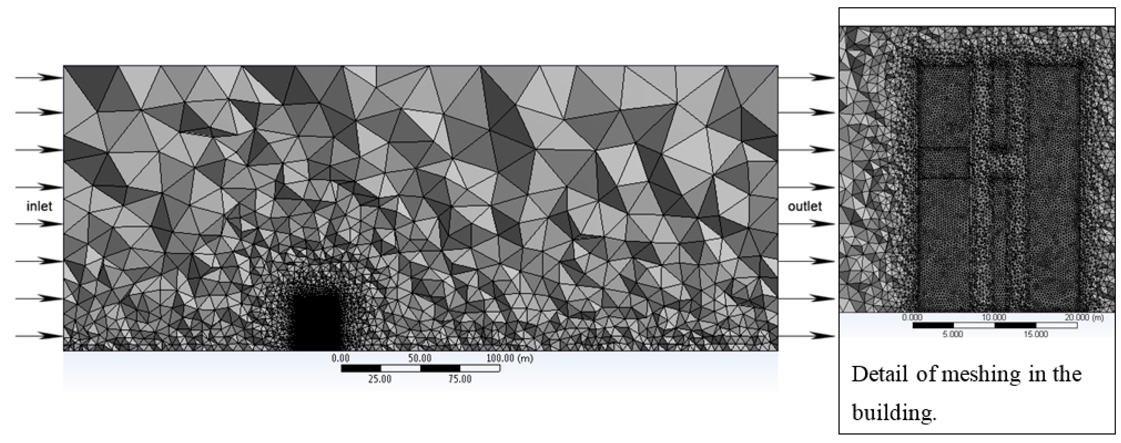
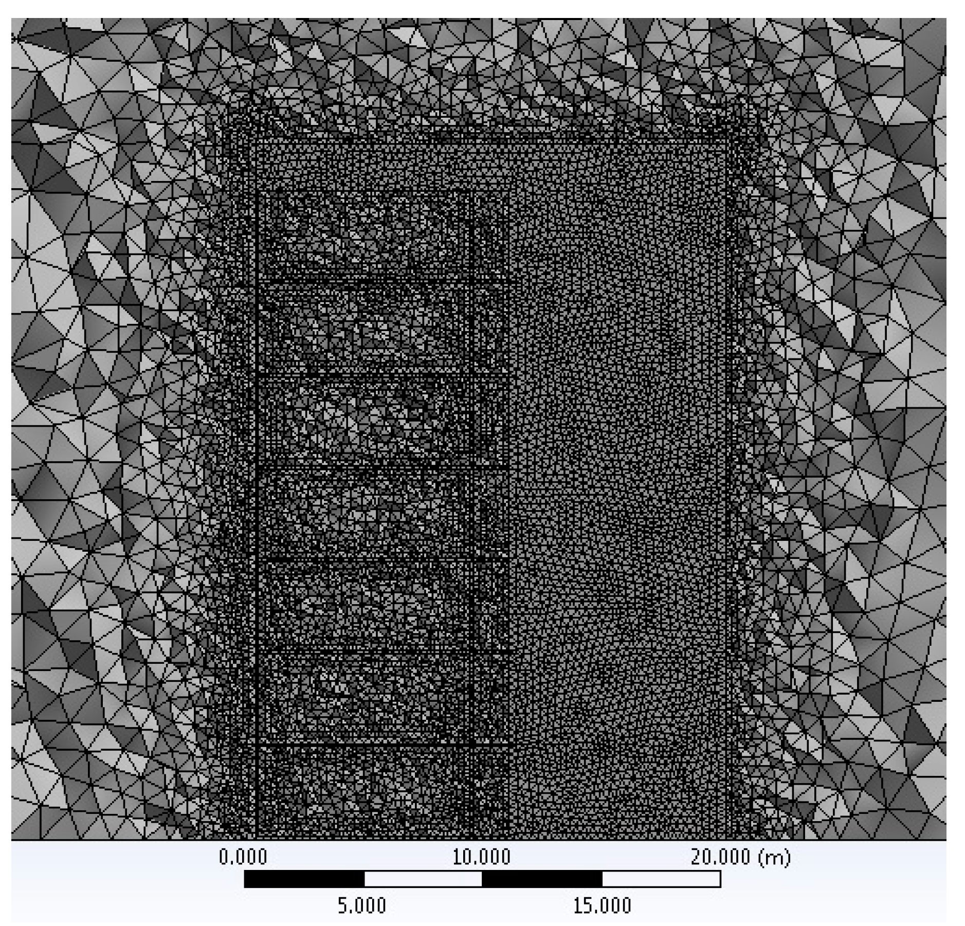
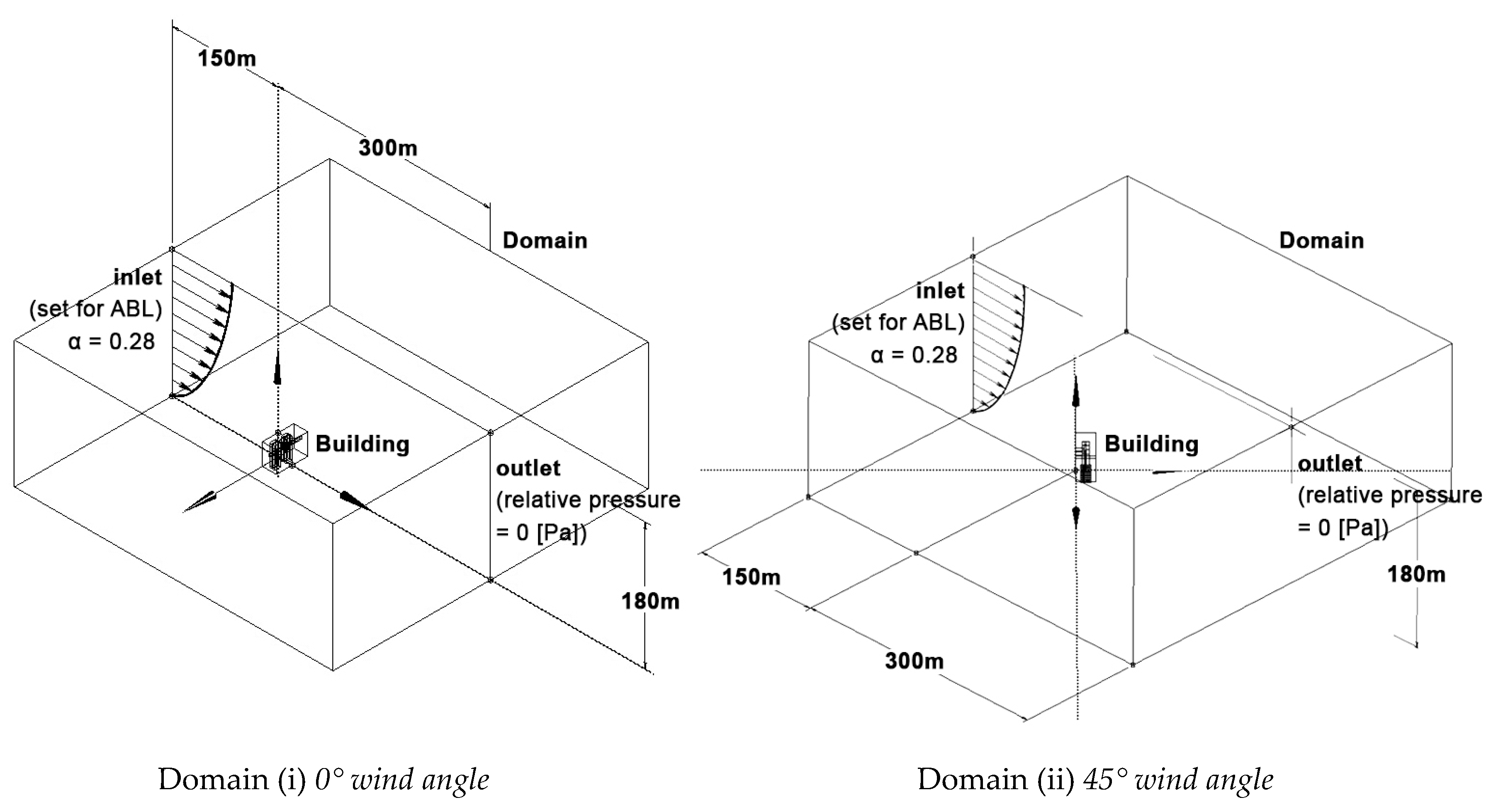
2.2. CFD Model: Geometry, Grid, Boundary Conditions and Solver Setup
3. Results and Findings
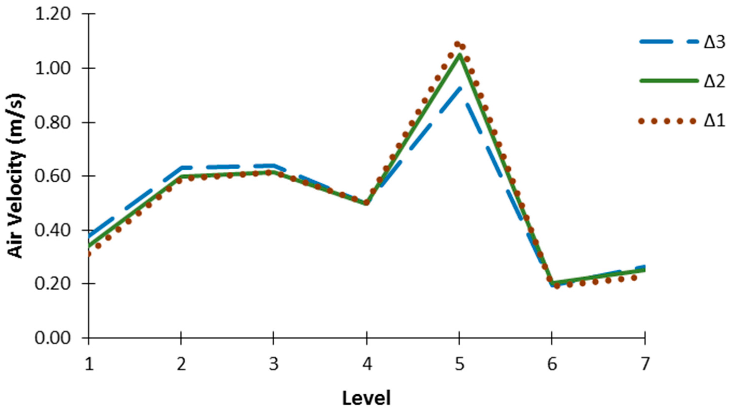
3.1. Mesh Independence Study
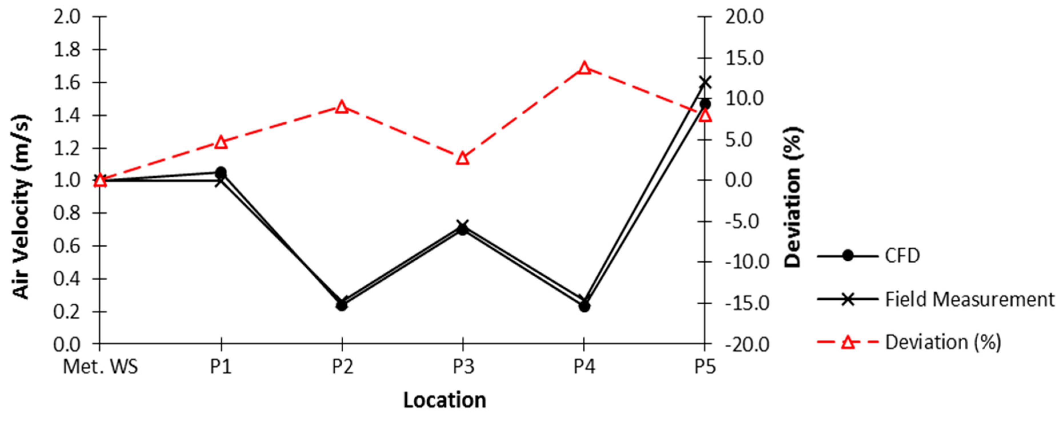
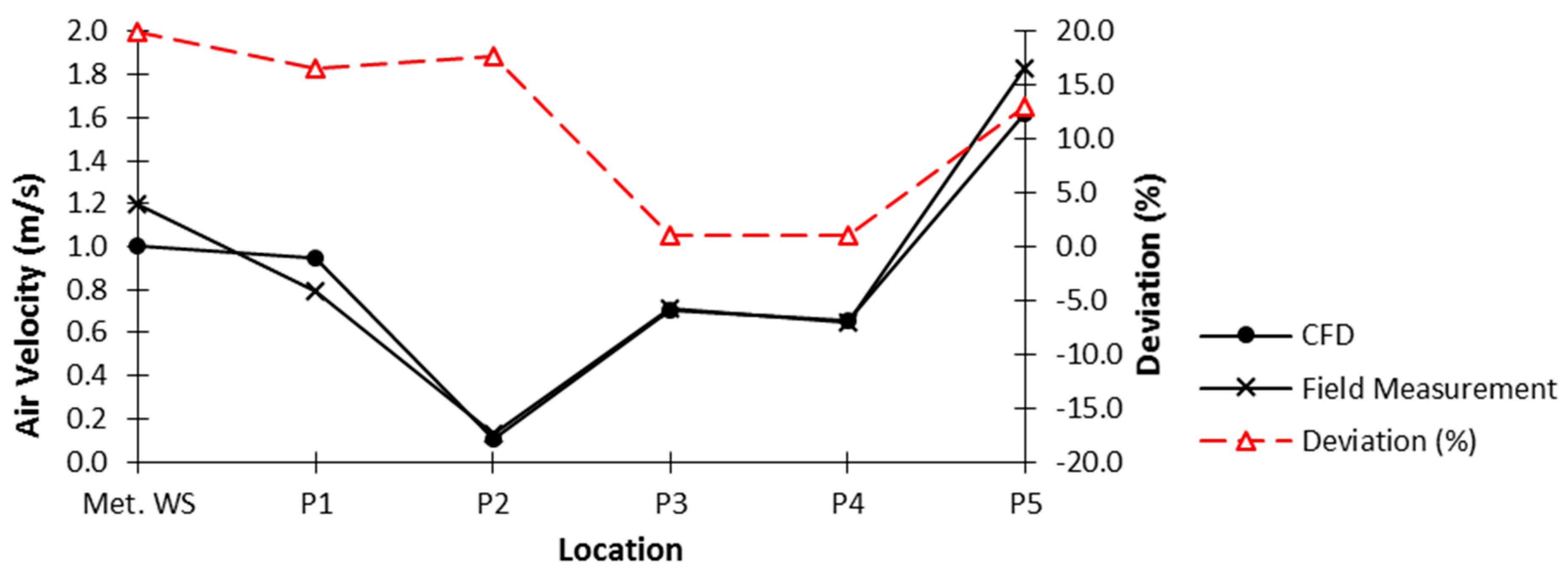
3.2. Validation of CFD Model with Field Measurement Data
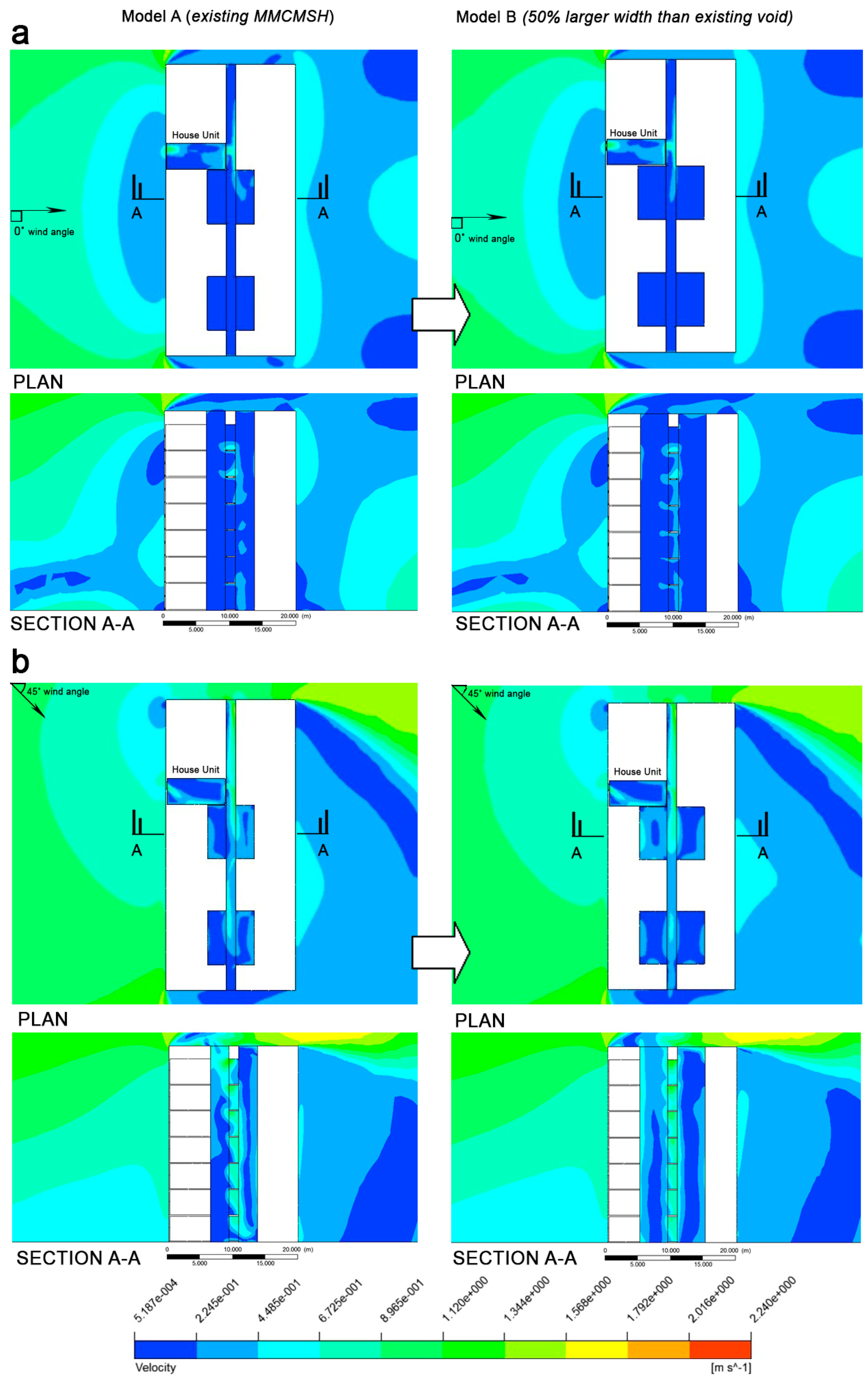
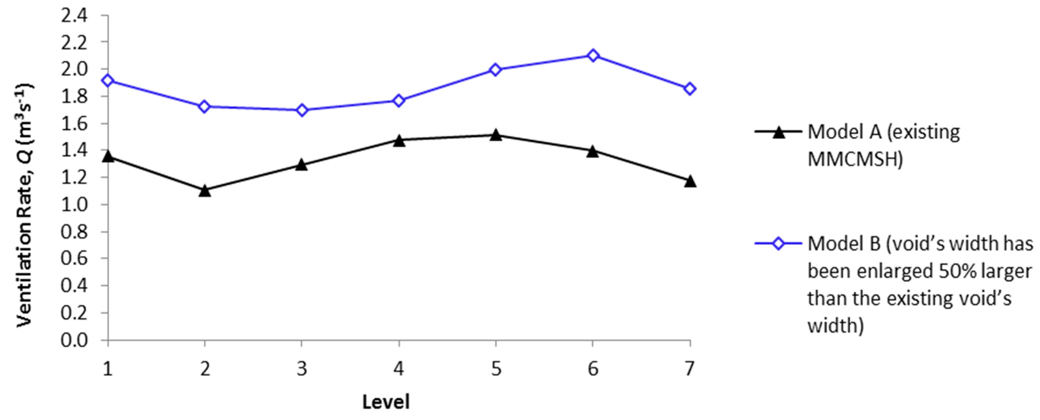
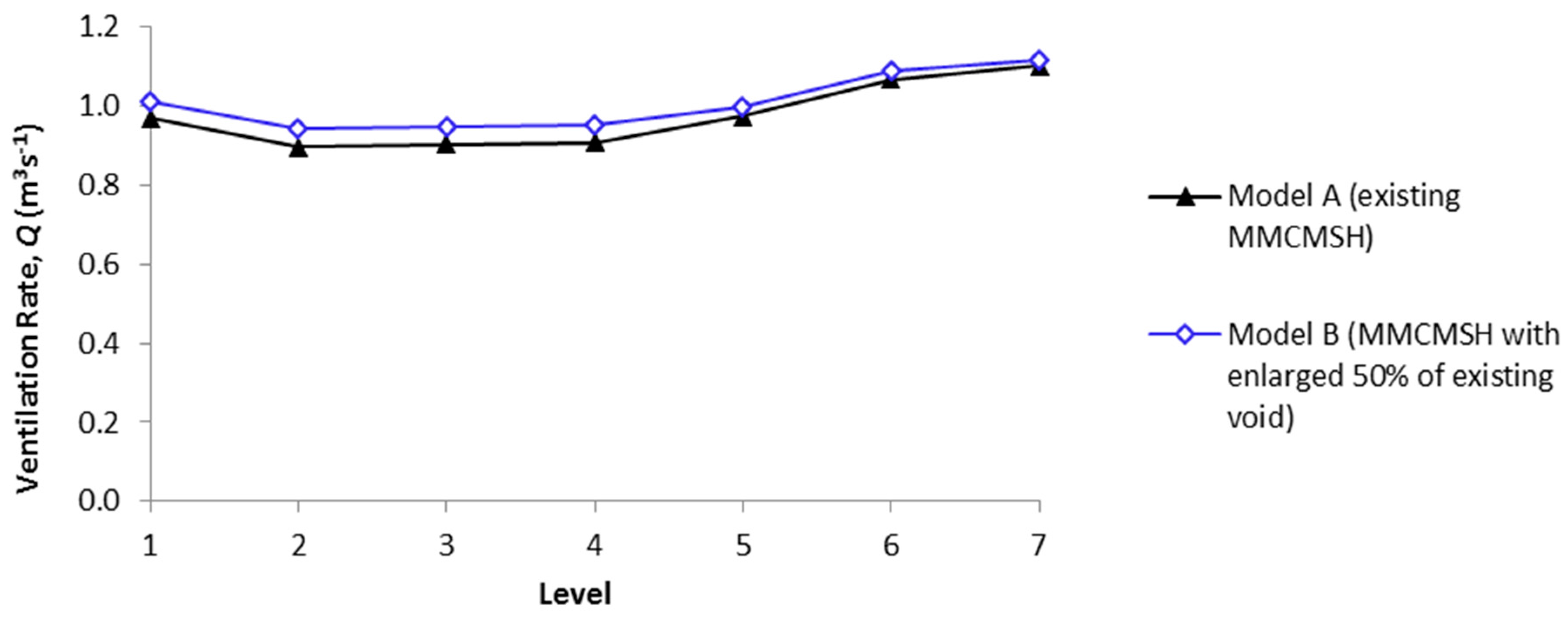
3.3. Natural Ventilation Performance between Two Different Configurations of Voids
4. Discussion
5. Conclusions
Acknowledgments
Author Contributions
Conflicts of Interest
References
- Jamaluddin, A.A.; Hussein, H.; Ariffin, A.R.M.; Keumala, N. A study on different natural ventilation approaches at a residential college building with the internal courtyard arrangement. Energy Build. 2014, 72, 340–352. [Google Scholar] [CrossRef]
- Kim, S.S.; Kang, D.H.; Choi, D.H.; Yeo, M.S.; Kim, K.W. Comparison of strategies to improve indoor air quality at the pre-occupancy stage in new apartment buildings. Build. Environ. 2008, 43, 320–328. [Google Scholar] [CrossRef]
- Prajongsan, P.; Sharples, S. Enhancing natural ventilation, thermal comfort and energy savings in high-rise residential buildings in Bangkok through the use of ventilation shafts. Build. Environ. 2012, 50, 104–113. [Google Scholar] [CrossRef]
- Zhou, C.; Wang, Z.; Chen, Q.; Jiang, Y.; Pei, J. Design optimization and field demonstration of natural ventilation for high-rise residential buildings. Energy Build. 2014, 82, 457–465. [Google Scholar] [CrossRef]
- Ibrahim, A.; Adam, N.M.; Yusoff, W.M.F. Application of Solar Induced Ventilation Prototype in a Single Storey Building in Hot and Humid Climate. In Proceedings of the Conference on Affordable Quality Housing, Putrajaya, Malaysia, 11–13 March 2013; pp. 53–59.
- Allard, F. Natural Ventilation in Buildings: A Design Handbook; James & James (Science Publishers) Ltd.: London, UK, 2002. [Google Scholar]
- Awbi, H. Ventilation Systems: Design and Performance; Taylor & Francis: New York, NY, USA, 2008. [Google Scholar]
- Kim, M.H.; Hwang, J.H. Performance prediction of a hybrid ventilation system in an apartment house. Energy Build. 2009, 41, 579–586. [Google Scholar] [CrossRef]
- Wang, Y.; Zhao, F.Y.; Kuckelkorn, J.; Liu, D.; Liu, J.; Zhang, J.L. Classroom energy efficiency and air environment with displacement natural ventilation in a passive public school building. Energy Build. 2014, 70, 258–270. [Google Scholar] [CrossRef]
- Farea, T.G.; Ossen, D.R.; Alkaff, S.; Kotani, H. CFD modeling for natural ventilation in a lightwell connected to outdoor through horizontal voids. Energy Build. 2015, 86, 502–513. [Google Scholar] [CrossRef]
- Cho, J.; Yoo, C.; Kim, Y. Viability of exterior shading devices for high-rise residential buildings: Case study for cooling energy saving and economic feasibility analysis. Energy Build. 2014, 82, 771–785. [Google Scholar] [CrossRef]
- Dola, K. Reaching a Balance: Does Supply Meet Demand? In Housing News; Housing Research Centre, UPM: Serdang, Malaysia, 2012; pp. 10–11. [Google Scholar]
- Lo, L.J.; Banks, D.; Novoselac, A. Combined wind tunnel and CFD analysis for indoor airflow prediction of wind-driven cross ventilation. Build. Environ. 2013, 60, 12–23. [Google Scholar]
- Tominaga, Y.; Stathopoulos, T. CFD simulation of near-field pollutant dispersion in the urban environment: A review of current modeling techniques. Atmos. Environ. 2013, 79, 716–730. [Google Scholar] [CrossRef]
- Karakatsanis, C.; Bahadori, M.N.; Vickery, B.J. Evaluation of pressure coefficients and estimation of air flow rates in buildings employing wind towers. Sol. Energy 1986, 37, 363–374. [Google Scholar] [CrossRef]
- Montazeri, H. Experimental and numerical study on natural ventilation performance of various multi-opening wind catchers. Build. Environ. 2011, 46, 370–378. [Google Scholar] [CrossRef]
- Van Hooff, T.; Blocken, B.; Aanen, L.; Bronsema, B. A venturi-shaped roof for wind-induced natural ventilation of buildings: Wind tunnel and CFD evaluation of different design configurations. Build. Environ. 2011, 46, 1797–1807. [Google Scholar] [CrossRef]
- Perén, J.I.; van Hooff, T.; Leite, B.C.C.; Blocken, B. CFD simulation of wind-driven upward cross ventilation and its enhancement in long buildings: Impact of single-span versus double-span leeward sawtooth roof and opening ratio. Build. Environ. 2016, 96, 142–156. [Google Scholar] [CrossRef]
- Etheridge, D. Natural Ventilation of Buildings: Theory, Measurement and Design; John Wiley & Sons, Ltd.: London, UK, 2012. [Google Scholar]
- Moosavi, L.; Mahyuddin, N.; Ghafar, N.A.; Ismail, M.A. Thermal performance of atria: An overview of natural ventilation effective designs. Renew. Sustain. Energy Rev. 2014, 34, 654–670. [Google Scholar] [CrossRef]
- Ray, S.D.; Gong, N.W.; Glicksman, L.R.; Paradiso, J.A. Experimental characterization of full-scale naturally ventilated atrium and validation of CFD simulations. Energy Build. 2014, 69, 285–291. [Google Scholar] [CrossRef]
- Kotani, H.; Satoh, R.; Yamanaka, T. Natural ventilation of light well in high-rise apartment building. Energy Build. 2003, 35, 427–434. [Google Scholar] [CrossRef]
- Ismail, A.M. Wind-Driven Natural Ventilation in High-Rise Office Buildings with Special Reference to the Hot-Humid Climate of Malaysia. Ph.D. Thesis, The Welsh School of Architecture, University of Wales College of Cardiff, Wales, UK, 1996. [Google Scholar]
- Murakami, S.; Kato, S.; Ooka, R.; Shiraishi, Y. Design of a porous-type residential building model with low environmental load in hot and humid Asia. Energy Build. 2004, 36, 1181–1189. [Google Scholar] [CrossRef]
- Hirano, T.; Kato, S.; Murakami, S.; Ikaga, T.; Shiraishi, Y. A study on a porous residential building model in hot and humid regions: Part 1—The natural ventilation performance and the cooling load reduction effect of the building model. Build. Environ. 2006, 41, 21–32. [Google Scholar] [CrossRef]
- Sadafi, N.; Salleh, E.; Haw, L.C.; Jaafar, Z. Evaluating thermal effects of internal courtyard in a tropical terrace house by computational simulation. Energy Build. 2011, 43, 887–893. [Google Scholar] [CrossRef]
- Kurabuchi, T.; Nagai, T. A two-node heat and mass transfer network model for long-term simulation of void space of high-rise apartment houses equipped with gas-fired boilers. In Proceedings of the 11th International IBPSA Conference, Glasgow, Scotland, 27–30 July 2009; pp. 434–441.
- Hussain, S.; Oosthuizen, P.H.; Kalendar, A. Evaluation of various turbulence models for the prediction of the airflow and temperature distributions in atria. Energy Build. 2013, 48, 18–28. [Google Scholar] [CrossRef]
- Hussain, S.; Oosthuizen, P.H. Numerical investigations of buoyancy-driven natural ventilation in a simple three-storey atrium building and thermal comfort evaluation. Appl. Therm. Eng. 2013, 57, 133–146. [Google Scholar] [CrossRef]
- Hussain, S.; Oosthuizen, P.H. Numerical investigations of buoyancy-driven natural ventilation in a simple atrium building and its effect on the thermal comfort conditions. Appl. Therm. Eng. 2012, 40, 358–372. [Google Scholar] [CrossRef]
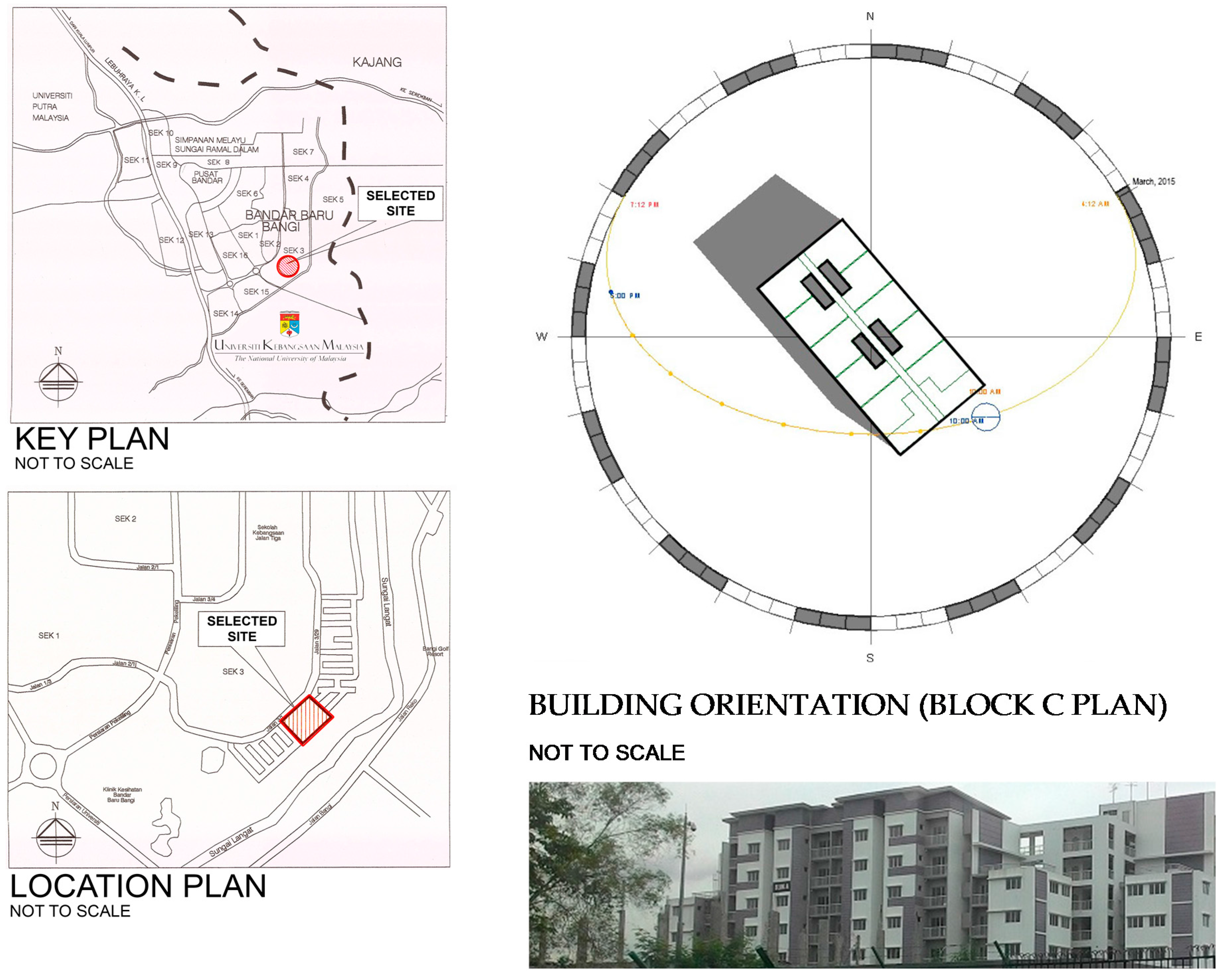
- PKNS. Rumah Pangsapuri Jenis Mampu Milik (Multi-Storey Affordable House), Seksyen 3, Bandar Baru; Bangi, B.P., Selatan, P.W., Eds.; PKNS (Perbadanan Kemajuan Negeri Selangor/Selangor State Development Corporation): Selangor, Malaysia, 2015. [Google Scholar]
- Mohamed, M.F.; King, S.; Behnia, M.; Prasad, D. The Effects of Balconies on the Natural Ventilation Performance of Cross-Ventilated High-Rise Buildings. J. Green Build. 2013, 9, 145–160. [Google Scholar] [CrossRef]
- Moonen, P.; Defraeye, T.; Dorer, V.; Blocken, B.; Carmeliet, J. Urban Physics: Effect of the micro-climate on comfort, health and energy demand. Front. Arch. Res. 2012, 1, 197–228. [Google Scholar] [CrossRef]
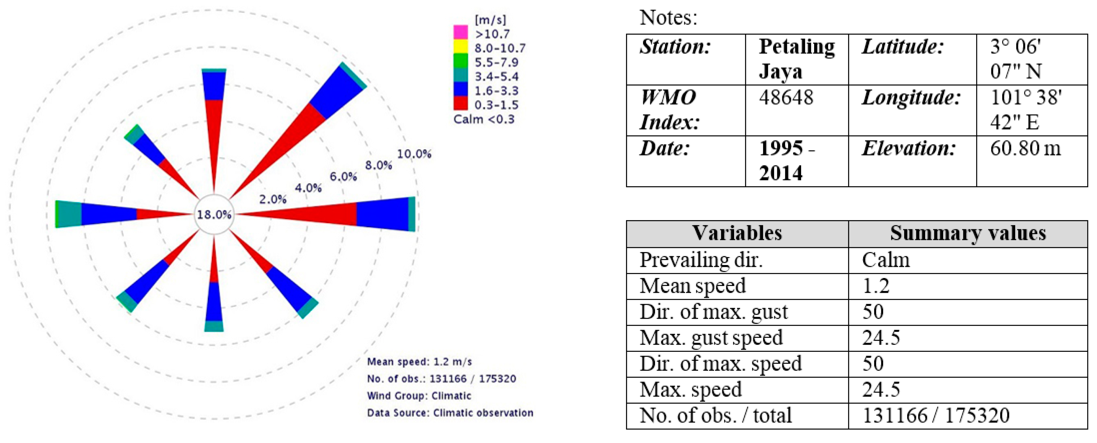
- Malaysian Meteorological Department, Annual Wind Rose (1995–2014); Malaysian Meteorological Department: Petaling Jaya, Malaysia, 2015.
- Malaysian Meteorological Department, Records of Maximum Surface Wind (2011–2015) & Hourly Mean Surface Wind for Month (March–April 2015); Malaysian Meteorological Department: Petaling Jaya, Malaysia, 2015.
- Tominaga, Y.; Mochida, A.; Yoshie, R.; Kataoka, H.; Nozu, T.; Yoshikawa, M.; Shirasawa, T. AIJ guidelines for practical applications of CFD to pedestrian wind environment around buildings. J. Wind Eng. Ind. Aerodyn. 2008, 96, 1749–1761. [Google Scholar] [CrossRef]
- Kwon, D.K.; Kareem, A. Comparative study of major international wind codes and standards for wind effects on tall buildings. Eng. Struct. 2013, 51, 23–35. [Google Scholar] [CrossRef]
- MS1553: 2002, Code of Practice on Wind Loading for Building Structure (Malaysian Standard); Department of Standards Malaysia (DSM) (Ed.) SIRIM Berhad: Putrajaya, Malaysia, 2010; pp. 22–24.
- Mendis, P.; Ngo, T.; Haritos, N.; Hira, A.; Samali, B.; Cheung, J. Wind Loading on Tall Buildings. Electron. J. Struct. Eng. 2007, 3, 41–54. [Google Scholar]
- Hajdukiewicz, M.; Geron, M.; Keane, M.M. Calibrated CFD simulation to evaluate thermal comfort in a highly-glazed naturally ventilated room. Build. Environ. 2013, 70, 73–89. [Google Scholar] [CrossRef]
- Mohamed, M.F.; King, S.; Behnia, M.; Prasad, D. Coupled Outdoor and Indoor Airflow Prediction for Buildings Using Computational Fluid Dynamics (CFD). Buildings 2013, 3, 399–421. [Google Scholar] [CrossRef]
- Ghiaus, C.; Allard, F. Natural Ventilation in the Urban Environment: Assessment and Design; Bath Press: Bath, UK, 2005. [Google Scholar]
- Atkinson, J.; Chartier, Y.; Silva, C.L.P.; Jensen, P.; Li, Y.; Seto, W.H. Natural Ventilation for Infection Control in Health-Care Settings; World Health Organization: Geneva, Switzerland, 2009. [Google Scholar]
- Uniform Building by-Laws 1984 [G.N. 5178/85]. In Third Schedule (By-law 41); International Law Book Services: Petaling Jaya, Malaysia, 2013.
- ANSYS. ANSYS Training Manual; ANSYS Inc.: Canonsburg, PA, USA, 2009. [Google Scholar]
- Celik, I.B.; Ghia, U.; Roache, P.J.; Freitas, C.J.; Coleman, H.; Raad, P.E. Procedure for Estimation and Reporting of Uncertainty Due to Discretization in CFD Applications. J. Fluids Eng. 2008, 130, 1–4. [Google Scholar]
- Eca, L.; Hoekstra, M. Discretization Uncertainty Estimation based on a Least Squares version of the Grid Convergence Index. In 2nd Workshop on CFD Uncertainty Analysis; Instituto Superior Tecnico: Lisbon, Portugal, 2006; pp. 1–27. [Google Scholar]
- Yusoff, W.F.M. Roof Solar Collector and Vertical Stack For Enhancing Indoor Ventilation of Single-Storey Shophouse in Malaysia. Ph.D. Thesis, Universiti Putra Malaysia, Serdang, Selangor, Malaysia, 2012. [Google Scholar]
- Tanasi´c, N.; Jankes, G.; Skista, H. CFD analysis and airflow measurements to approach large industrial halls energy efficiency: A case study of a cardboard mill hall. Energy Build. 2011, 43, 1200–1206. [Google Scholar] [CrossRef]
- Meroney, R.N. CFD Prediction of Airflow in Buildings for Natural Ventilation. In Proceedings of the 11th Americas Conference on Wind Engineering, San Juan, Puerto Rico, 22–26 June 2009.
- Perén, J.I.; van Hooff, T.; Leite, B.C.C.; Blocken, B. CFD analysis of cross-ventilation of a generic isolated building with asymmetric opening positions: Impact of roof angle and opening location. Build. Environ. 2015, 85, 263–276. [Google Scholar] [CrossRef]
- Ramponi, R.; Blocken, B. CFD simulation of cross-ventilation flow for different isolated building configurations: Validation with wind tunnel measurements and analysis of physical and numerical diffusion effects. J. Wind Eng. Ind. Aerodyn. 2012, 104–106, 408–418. [Google Scholar] [CrossRef]
- Ramponi, R.; Blocken, B. CFD simulation of cross-ventilation for a generic isolated building: Impact of computational parameters. Build. Environ. 2012, 53, 34–48. [Google Scholar] [CrossRef]
- Blocken, B.; Stathopoulos, T.; Carmeliet, J. CFD simulation of the atmospheric boundary layer: Wall function problems. Atmos. Environ. 2007, 41, 238–252. [Google Scholar] [CrossRef]
- Staudt, K. Determination of the Atmospheric Boundary Layer Height in Complex Terrain during SALSA 2005. Ph.D. Thesis, Department of Micrometeorology, University of Bayreuth, Bayreuth, Germany, 2006. [Google Scholar]
- Cochran, B.C. The Influence of Atmospheric Turbulence on the Kinetic Energy Available During Small Wind Turbine Power Performance Testing; CEDER-CIEMAT: Soria, Spain, 2002. [Google Scholar]


| No. | Label | Equipment | Location | Parameter | Accuracy |
|---|---|---|---|---|---|
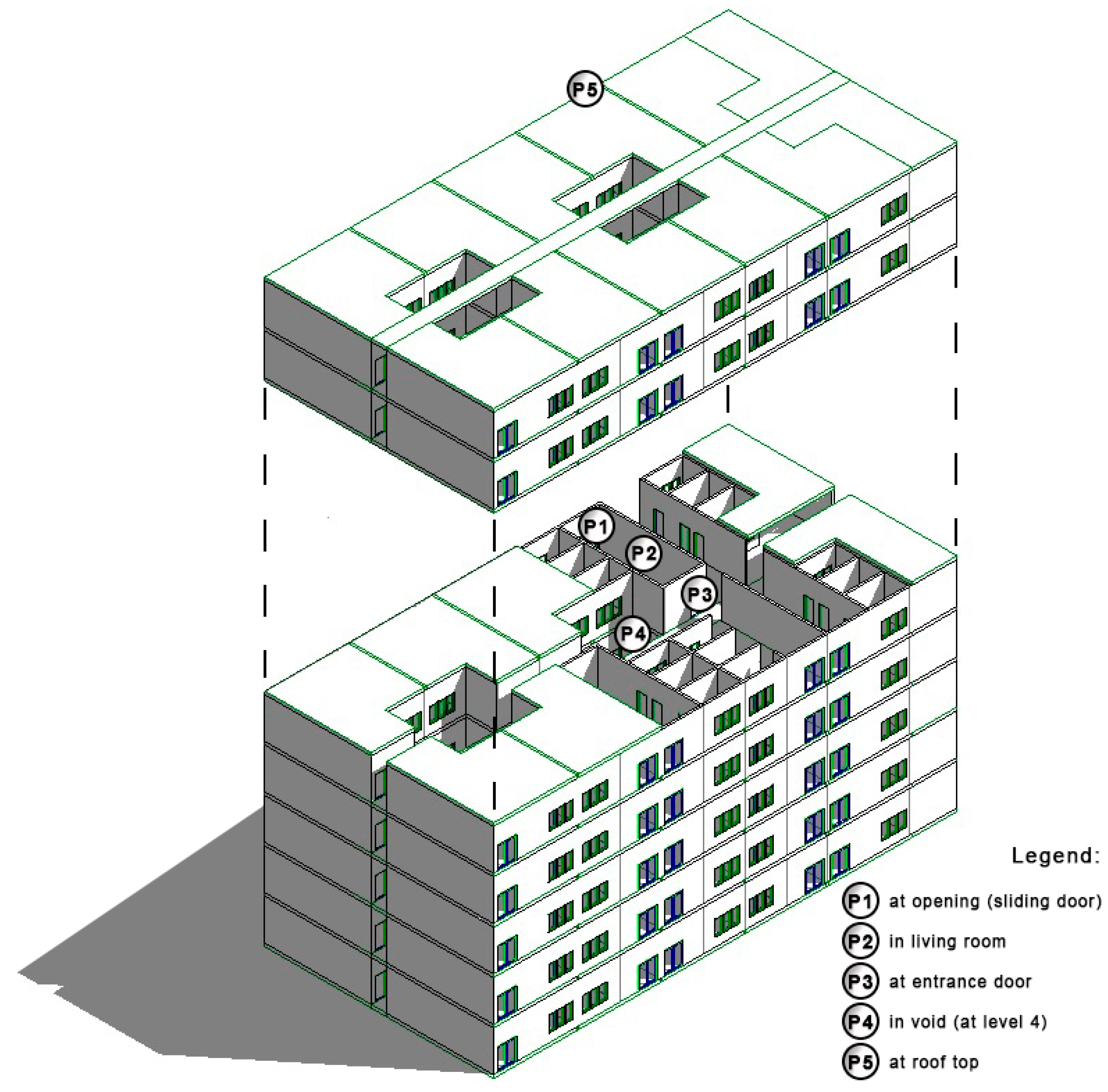
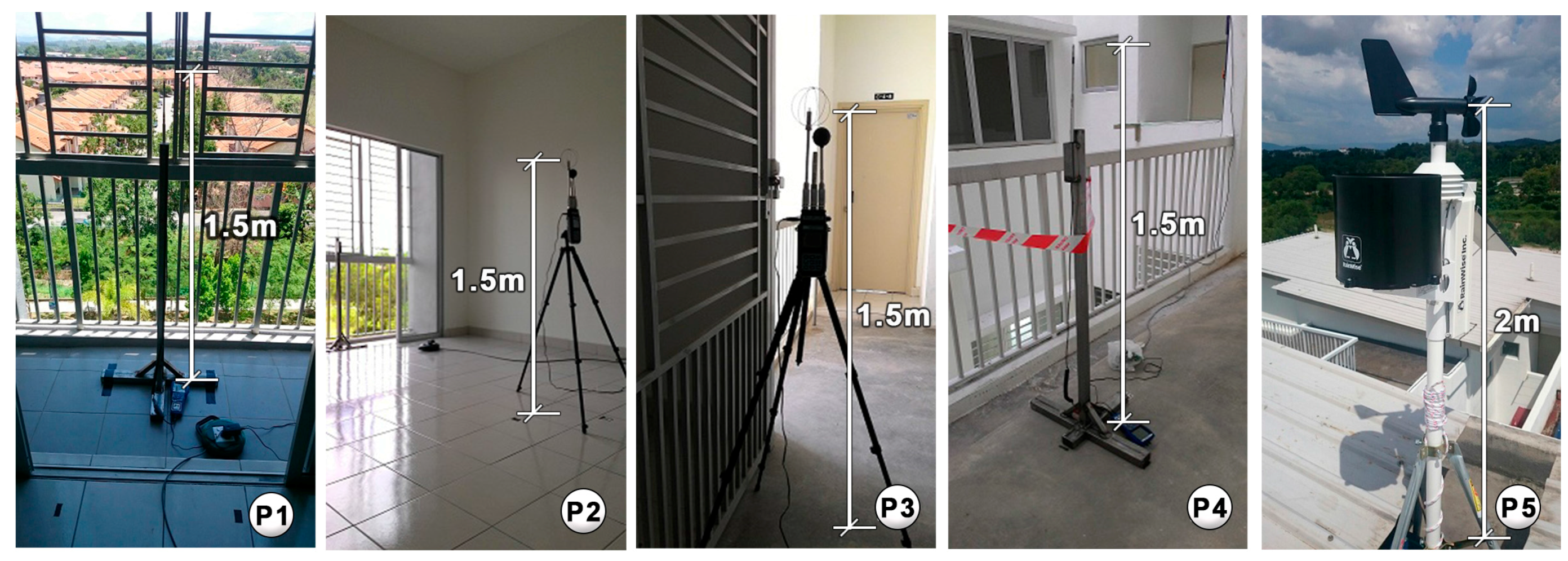
| 1. | P1 | Air Velocity Meter (Velocicalc® Model 9565) | Inlet OP (opening—at sliding door) | Air Velocity | ±0.02 m/s |
| 2. | P2 | Thermal Comfort Meter (DeltaOhm PMV AP3203) | Living (in living room) | Air Velocity | ±0.01 m/s |
| 3. | P3 | Thermal Comfort Meter (DeltaOhm PMV AP3203) | Outlet OP (opening—at entrance door) | Air Velocity | ±0.01 m/s |
| 4. | P4 | Air Velocity Meter (Velocicalc® Model 9565) | Void L4 (in void at level 4) | Air Velocity | ±0.02 m/s |
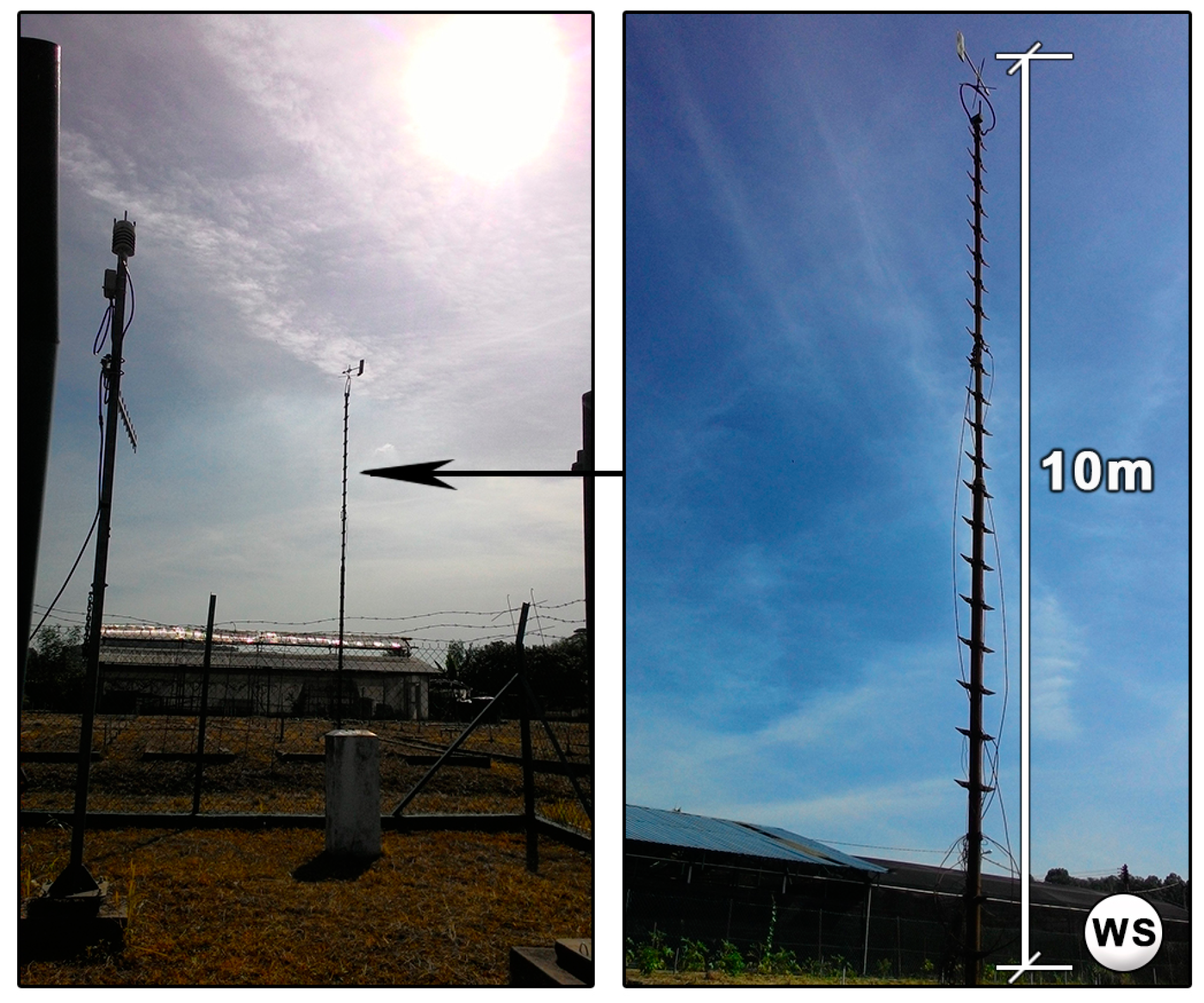
| 5. | P5 | Weather Station (WS) RainWise Inc. BioClear | Roof top (at roof top) | Wind Speed | ±0.10 m/s |
| Boundary | Type | Details | |
|---|---|---|---|
| Surface facing to NE | Inlet | Mass and momentum | Turbulence |
| Normal speed, | Medium (Intensity = 5%) | ||
| Surface facing to SW | Outlet | Average Static Pressure, Prelative = 0 (Pa) Pres. Profile Blend = 0.05 Average over whole outlet | |
| Surface facing to SE | Wall | No slip wall | |
| Surface facing to NW | Wall | No slip wall | |
| Building surfaces | Wall | No slip wall | |
| Ground surface | Wall | No slip wall | |
| Settings | Details |
|---|---|
| Advection Scheme | Specified Blend Factor = 0.75 |
| Turbulence Numerics | High Resolution |
| Convergence Control | Min. Iteration = 1 |
| Max. Iteration = 1000 | |
| Physical Timescale Control = 500 (s) | |
| Convergence Criteria | Residual Type = RMS |
| Residual Target = 0.0001 |
| ∆3 | ∆2 | ∆1 | r32 | r21 |
|---|---|---|---|---|
| 71 727 | 2 723 337 | 6 581 327 | 1.56 | 1.34 |
| Sensor Location | CFD | R | Convergence Type | E32 | E21 | Measure | Measurement Accuracy (±) | ||
|---|---|---|---|---|---|---|---|---|---|
| ∆3 | ∆2 | ∆1 | |||||||
| P1 | 0.92 | 1.05 | 1.11 | 0.44 | Monotonic conv. | 0.12 | 0.05 | 1.00 | 0.05 |
| P2 | 0.56 | 0.24 | 0.24 | −0.01 | Oscillatory conv. | 0.97 | 0.01 | 0.26 | 0.02 |
| P3 | 0.73 | 0.70 | 0.73 | −1.28 | Oscillatory diverg. | n/a | n/a | 0.72 | 0.02 |
| P4 | 0.22 | 0.23 | 0.16 | −6.68 | Oscillatory diverg. | n/a | n/a | 0.27 | 0.04 |
| P5 | 1.47 | 1.47 | 1.46 | −3.66 | Oscillatory diverg. | n/a | n/a | 1.60 | 0.13 |
| No. | Location | CFD | Field Measurement | Deviation (%) |
|---|---|---|---|---|
| 1 | Met. WS | 0.99 | 1.00 | 0.14 |
| 2 | P1 | 1.05 | 1.00 | 4.83 |
| 3 | P2 | 0.24 | 0.26 | 9.06 |
| 4 | P3 | 0.70 | 0.72 | 2.75 |
| 5 | P4 | 0.23 | 0.27 | 13.86 |
| 6 | P5 | 1.47 | 1.60 | 8.00 |
| Average: | 6.44 |
| No. | Location | CFD | Field Measurement | Deviation (%) |
|---|---|---|---|---|
| 1 | Met. WS | 1.00 | 1.20 | 19.94 |
| 2 | P1 | 0.95 | 0.79 | 16.67 |
| 3 | P2 | 0.11 | 0.13 | 17.73 |
| 4 | P3 | 0.70 | 0.71 | 1.05 |
| 5 | P4 | 0.66 | 0.65 | 1.12 |
| 6 | P5 | 1.62 | 1.83 | 13.07 |
| Average: | 11.60 |
© 2016 by the authors; licensee MDPI, Basel, Switzerland. This article is an open access article distributed under the terms and conditions of the Creative Commons Attribution (CC-BY) license (http://creativecommons.org/licenses/by/4.0/).
Share and Cite
Muhsin, F.; Mohammad Yusoff, W.F.; Mohamed, M.F.; Sapian, A.R. The Effects of Void on Natural Ventilation Performance in Multi-Storey Housing. Buildings 2016, 6, 35. https://doi.org/10.3390/buildings6030035
Muhsin F, Mohammad Yusoff WF, Mohamed MF, Sapian AR. The Effects of Void on Natural Ventilation Performance in Multi-Storey Housing. Buildings. 2016; 6(3):35. https://doi.org/10.3390/buildings6030035
Chicago/Turabian StyleMuhsin, Fakhriah, Wardah Fatimah Mohammad Yusoff, Mohd Farid Mohamed, and Abdul Razak Sapian. 2016. "The Effects of Void on Natural Ventilation Performance in Multi-Storey Housing" Buildings 6, no. 3: 35. https://doi.org/10.3390/buildings6030035
APA StyleMuhsin, F., Mohammad Yusoff, W. F., Mohamed, M. F., & Sapian, A. R. (2016). The Effects of Void on Natural Ventilation Performance in Multi-Storey Housing. Buildings, 6(3), 35. https://doi.org/10.3390/buildings6030035