1. Introduction
Computer-aided design (CAD) techniques have been in use by the construction industry since the early 1980s. The next paradigm shift was the introduction of building information modelling (BIM) in the field of architecture, engineering and construction (AEC) in the mid-1990s [
1].
BIM is a methodology enabled by a set of software tools and processes for facilitating the creation and use of the digital representation of the physical and functional characteristics of a facility [
2]. In terms of software, BIM introduces exchangeable information formats,
i.e., International Foundation Classes (IFC), for modelling and visualizing building entities in 3D. In terms of processes, BIM facilitates the conveyance of building information from the design phase throughout the building life cycle, supporting cost management, construction management and facility management [
3].
Thus, research on BIM as a methodology has been focused on the following two areas: (i) development of software tools and techniques for creating and evaluating new BIM artefacts that arise as building designs and technologies evolve; and (ii) the application and usage of BIM processes across the life-cycle of a building from pre-construction design to post-construction facility management.
Recent rapid advances in information and communication technologies (ICT) have led to their pervasive use across industry sectors, including building construction. An upcoming and important aspect of ICT use that we anticipate to take a central stage is the construction and management of emerging smart built environments (SBEs). Here, “smart built environment” refers to a built environment that has been embedded with smart objects, such as sensors and actuators, with computing and communication capabilities, making the environment sufficiently ‘smart’ to interact intelligently with and support their human users in their day-to-day activities [
4].
In a smart building, the human users refer not only to the building occupants, but also to the building’s owners/managers. The former are typically concerned with how a smart building could improve personal safety, comfort and productivity, while the latter are more concerned with how a smart building could better support their operation and management of the building. In addition, as buildings are a major source of energy consumption, accounting for 40% of primary energy consumption in most countries [
5], SBE will be expected to harness its new technological capabilities to achieve an unprecedented level of energy efficiency.
Therefore, constructing SBEs can have a set of requirements and procedures not defined or typically considered in traditional construction settings. Although there has been research conducted on various aspects of SBEs, very little attention has been focused on the role and application of BIM in the pre- and post-construction processes of SBEs.
Therefore, in this paper, we investigate how BIM can contribute to the pre-construction design and post-construction management phases of SBE. The rest of the paper is organized as follow: in
Section 2, we review related works. In
Section 3, we introduce the general challenges and the opportunities for BIM in SBE. In
Section 4, BIM is first extended in the building design phase to provide material/device profiling and an information exchange interface for sensors, smart meters and DERs. In
Section 5, a facility management tool is developed to provide advanced energy management functions based on BIM produced in the previous phase. Finally,
Section 6 concludes the paper.
2. Literature Review
In this section, we review the state-of-the-art on the design and management of smart built environments, as well as related BIM applications.
2.1. Design and Management of SBE
The design and management of SBE generally focus on two aspects: service and sensing. The service refers to that provided by SBE to support users in their daily lives. The authors in [
6] discuss the service life cycle and design principles for a management framework to effectively manage autonomous and adaptive services in smart spaces. In [
7], a smart shadow system was proposed to provide home users with real-world services, defined as services that affect the real world by changing the user’s environmental factors, such as air conditioning and lighting, and to dynamically detect and resolve service conflicts.
On the other hand, some design approaches consider sensing as one essential component of SBE. The authors in [
8] utilize a logic-based modelling language TCOZ (Timed Communicating Object Z) to describe constraints of the sensor imposed by its environmental conditions or relations with other sensors and its sensing pattern, such as periodic or conditional sensing. The sensor-based model was then applied to the design of smart spaces. In [
9], ECA (event, condition, action) rules are introduced for describing home-based sensor-driven services, which can often cause a chain reaction,
i.e., one service may generate an outcome that automatically triggers another service. Therefore, a method is proposed to detect such service chains and the possible conflicts among these services.
3. Utilizing BIM in Smart Built Environments
As mentioned before, a variety of smart objects will be ubiquitously and transparently installed in SBE to perform actions, such as sensing and control. These smart objects may interact with each other and with the environment and the environment users. The communication can be carried by either wireless (e.g., ZigBee, 802.11a/b/g/n) or wired (e.g., Ethernet, power line) information networks.
3.1. General Challenges
A number of questions arise when considering the life cycle of a smart built environment. First is how the smart objects are embedded in the environment. From the aspect of sensors, the physical location and the surrounding settings can significantly affect their ability to carry out specific tasks, e.g., ambient light or occupancy sensing. From the aspect of the information network, whether a wireless sensor network (WSN) or wired Ethernet is deployed, it should be designed to offer the smart objects an excellent level of communication.
Second is how the smart objects interact with the environment. The smart objects are situated in a specific surrounding to carry out their tasks and often require the input of space data, such as building floor plans. Furthermore, in carrying their tasks, the confluence of the actions by different smart objects may involve affecting a common set of environment factors, the impact of which should be studied and understood within a spatial context. Last, but not least, when conducting a building performance analysis, such as an energy efficiency analysis of the SBE, not only the information from sensors/meters is vital, but the building architectural/geometry data are also indispensable.
Third is the maintenance of such smart objects in a building’s post-construction phase. In building management, it is common for facility managers to complain about either incomplete or inaccurate (not up-to-date) documentation [
18]. To maintain a smart built environment that is more complicated than traditional structures, more building design and construction data will need to be documented and conveyed to the facility managers. In the event that the company that designed and constructed the building is no longer in business, building management can continue to function properly provided that the documented information is both comprehensive and reliable.
3.2. Introducing BIM in Smart Built Environments
BIM hosts the collaborative architectural information and provides the semantic knowledge of the building. With the emergence of smart built environment technology, BIM should be further developed to be capable of seamlessly integrating smart objects in building design, verifying the SBE design and feeding smart objects with relevant building-related information.
Designing SBE with BIM is both advantageous and convenient. Firstly, designers of SBE can utilize the building knowledge of BIM for planning the layouts of sensors, tags, actuators and meters. The performance of smart objects can be verified against known constraints and their layouts optimized for the best functional performance. Secondly, BIM also serves as a data repository for the physical information of smart objects. For maintenance and asset tracking in the building post-construction phase, the hardware information of smart objects can be recorded, and their installation locations can be documented and visualized in 3D.
On the other hand, BIM provides a perfect ontology database for SBE. Smart objects may be designed and manufactured by different vendors. The data they provide may vary in structure, and they may communicate using different protocols. Middleware is a popular approach to addressing such issues with heterogeneous smart objects [
19]. With the introduction of BIM, each smart object can be profiled through its information exchange interface. Because BIM is standard compliant, the middleware can extract data formats of smart objects and other building information for viewing as an ontology database.
3.3. Energy Management in Smart Built Environments
Energy management is an important part of facility management. In SBEs, energy management can be enhanced through smart objects, such as temperature, occupancy and ambient light sensors, that provide data for estimating the building’s energy requirements, understanding the building’s energy usage patterns and decision-making by building control systems to achieve a balance between a building’s energy efficiency and the comfort level of its occupants.
As awareness of energy efficiency grows within the building industry, the trend of deploying various sensors in the buildings will only become more common in energy management practice. Furthermore, with the introduction of a smart grid, buildings have an active role in the power system, as they exchange electrical power information with the power grid via their smart meters [
20]. Sub-metering systems are also important to achieve energy awareness for building management, as they can provide high-resolution monitoring data down to the individual appliance level.
Another significant aspect that challenges energy management today is the penetration of DERs, such as photovoltaic (PV) panels and micro wind turbines. With on-site DERs, the role of building changes from a pure energy consumer to both an energy producer and consumer (or “prosumer”) [
21]. Correspondingly, the role of SBE is also extended to include the tasks of performing energy generation forecast, load scheduling, storing and feeding energy back to the grid. The monitoring and control of DERs is therefore vital for energy management in SBEs.
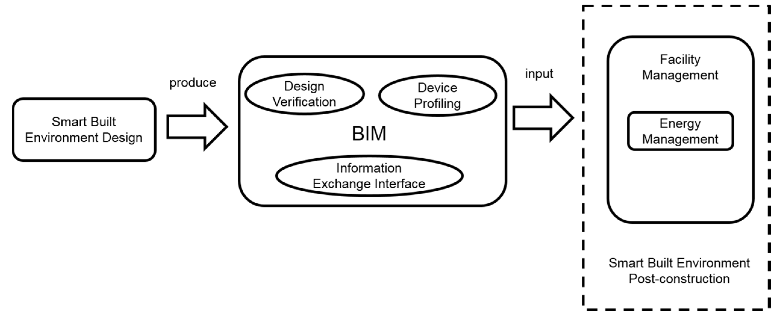
In essence, smart meters and DERs can be viewed as real-time information objects, which are a type of smart object that can be embedded in the BIM design of SBE, and the energy management system can benefit from the profiling capability of BIM, as shown in
Figure 1.
Figure 1.
Role of building information modelling (BIM) in smart built environments.
Figure 1.
Role of building information modelling (BIM) in smart built environments.
4. Designing Smart Built Environment with BIM
As discussed in the previous section, BIM has the potential to support the entire life-cycle of the SBE. Therefore, we started by investigating how existing BIM platforms can be further developed to better support the design of SBE. To date, the most popular BIM software is the Revit suite from Autodesk and Archicad from Graphisoft. In this work, we have conducted our SBE design in BIM with Revit, but similar work can be conducted as well in Archicad.
4.1. Embedding Smart Objects in BIM
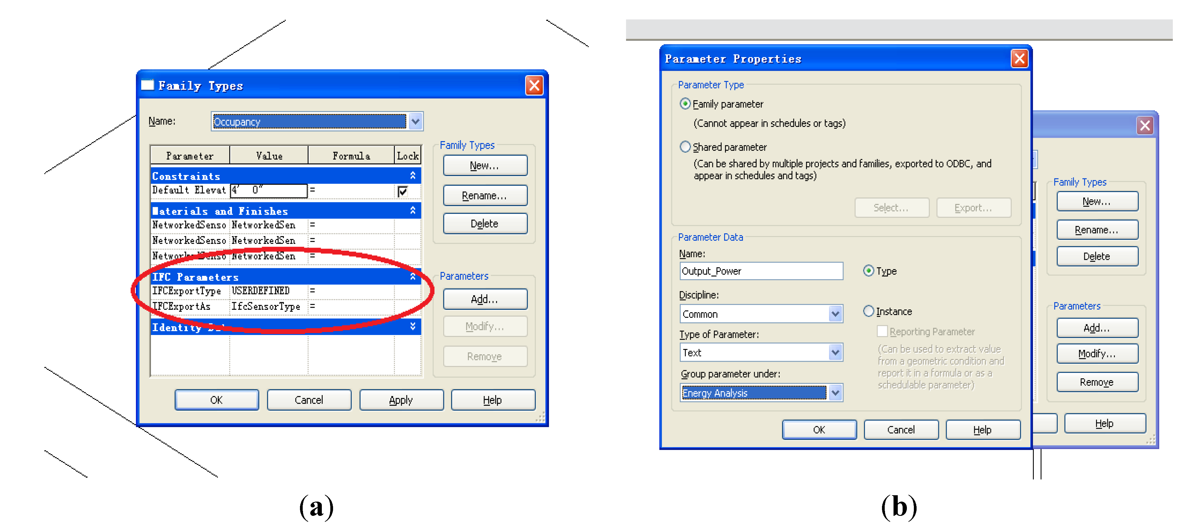
The intention is to profile smart objects with Revit during the SBE design phase. The produced BIM model with smart objects should be correctly exported as an International Foundation Class (IFC) file, so that other BIM tools can parse the information. We adopted three methods for the profiling: IFC shared parameter, family property parameter and the mark tag. The work in [
20] demonstrated how sensors can be modelled in Revit, and we took a similar approach, which uses the IFC shared parameter field to indicate the sensor type in IFC, as shown in
Figure 2a. For actuators, new properties can be added to the building element that is being controlled by the actuator. Therefore, new BIM artefacts, such as a smart window (e.g., capable of self-actuating to adjust its light transmission properties), can be created using the original window family with added actuator properties.
The IFC shared parameter enables the new smart object family to be a compatible type in BIM, i.e., exportable and parsable in IFC format. However, to fully model an SBE design, we have to provide additional information. For that purpose, we utilize the family property parameters for a type of smart object and mark tag for an individual smart object.
Figure 2.
(a) Extending BIM design using the “IFC shared parameter”; (b) Adding new parameter properties in Revit.
Figure 2.
(a) Extending BIM design using the “IFC shared parameter”; (b) Adding new parameter properties in Revit.
4.1.3. Identification and Service Mapping
Finally, to map a smart object from BIM to an individual real-world device, the mark tag in BIM is used. The BIM software, which parses the produced BIM file, reads the mark tag for the smart object and determines additional runtime information, e.g., the Internet Protocol (IP) address, of the device from a database. This tag is also used to map a smart object to a service descriptor file, which will be detailed in the next section.
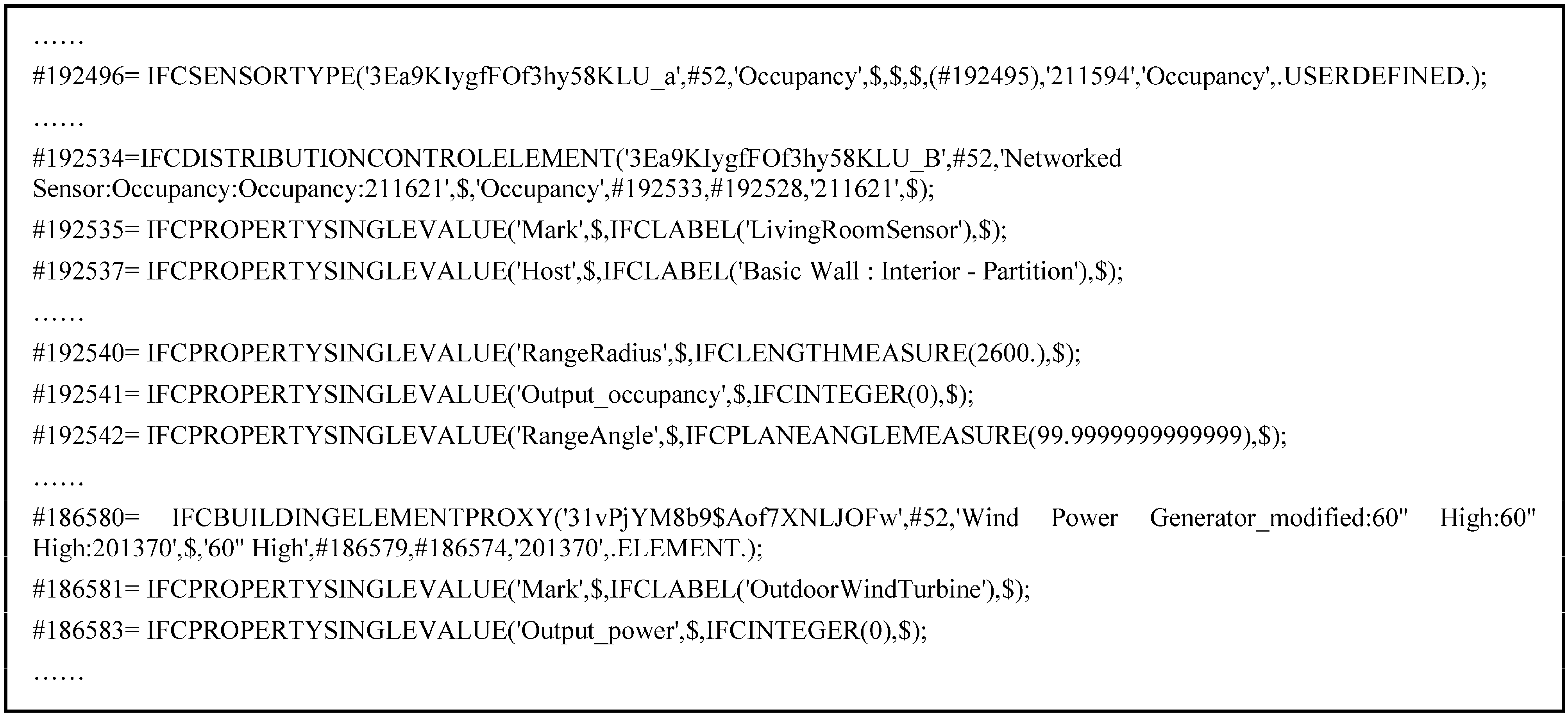
Using Revit, we created an SBE design, which is modelled as a smart house with sensors, actuators, smart meters, PV panel and wind turbine. After completing the BIM design, a BIM file in IFC format is generated, as shown in
Figure 4.
Figure 4.
Code segment of the BIM IFC file.
Figure 4.
Code segment of the BIM IFC file.
4.2. Design Verification Framework for SBE
Recall that SBE serves to enhance the building’s efficiency, security and comfort of its human occupants by being aware of the state of the environment and performing autonomous intelligent actions. Such actions performed by the SBE can be viewed as provisioning a type of service to the building owner or occupants. In literature, these services are also referred to as real-world services (RWS) [
7]. Designing a set of adaptive RWS with various smart objects could become an integral part of future SBE design.
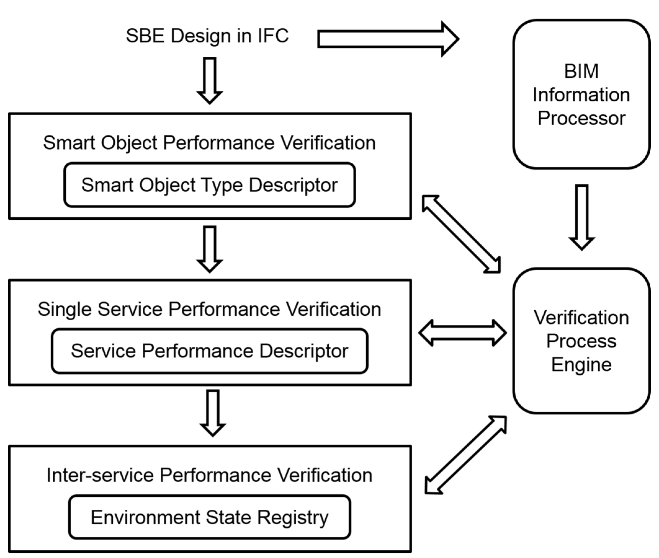
During the design phase of SBE, uncertainties may arise that could affect the service integrity and performance. For example, there could be doubts about whether the sensors are placed in the best locations to execute their tasks or whether there are conflicting objectives/requirements between different services. If such uncertainties can be verified during the design phase of the SBE, it may reduce the amount of rework necessary after the building is built. Furthermore, it can be useful for as-built verification, e.g., when new smart objects and services are to be introduced to an already constructed SBE. With this motivation, we propose an SBE design verification framework with BIM, as outlined in
Figure 5.
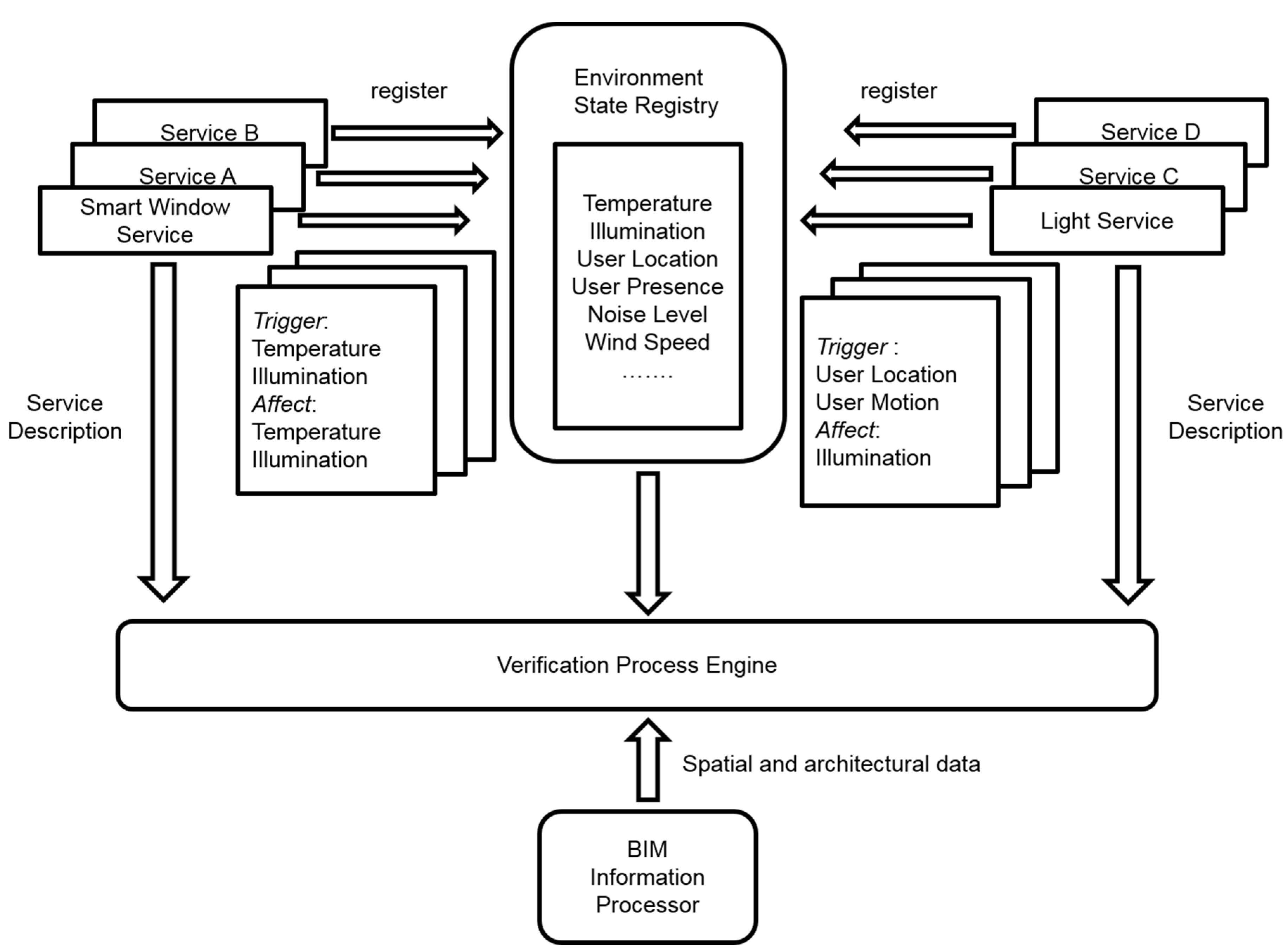
In this framework, a three-layer verification is adopted to verify the SBE design. The three layers are: smart object, single service and inter-service performance verification. The input to the framework is the BIM file produced as discussed in
Section 4.1 (in IFC format), which contains the design information of the building and associated smart objects. The performance verification criteria are modelled using XML, which are detailed in the following sections.
Figure 5.
Design verification framework for smart built environments (SBEs) with BIM.
Figure 5.
Design verification framework for smart built environments (SBEs) with BIM.
5. Integrating BIM in Post-Construction Facility Management
The BIM file generated from Revit and validated using the verification framework in the previous section is an output from the SBE designer or architect during the building design phase. In the post-construction facility management phase, the building manager can apply the information in this BIM file to perform day-to-day building management, including energy management.
To parse the BIM file and read the profiled information, there are two possible options for the design of this research. The first is to extend Revit using a native software development kit (SDK) to perform the energy management task. The second is to develop a standalone BIM tool as a separate energy management engine. After much contemplation, we decided to go with the second option, as we believe that building managers will be more familiar with using a building management system (BMS) for their everyday work than with Revit, which is intended as a computer-aided design (CAD) tool for building designers and architects.
Therefore, we opted for the second option, and a stand-alone BIM tool for energy management has been developed. We developed the tool using the extensible building information modelling [
23] toolkit, which provides IFC parsing and 3D presentation utilities.
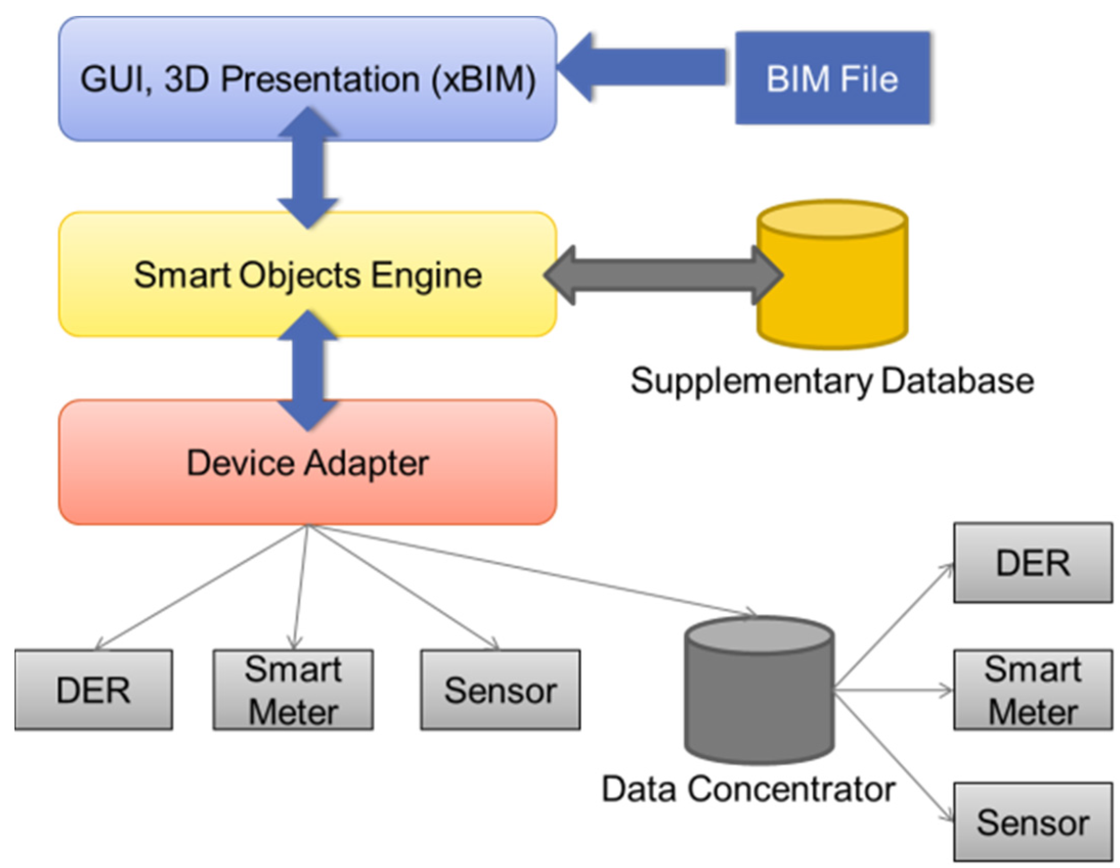
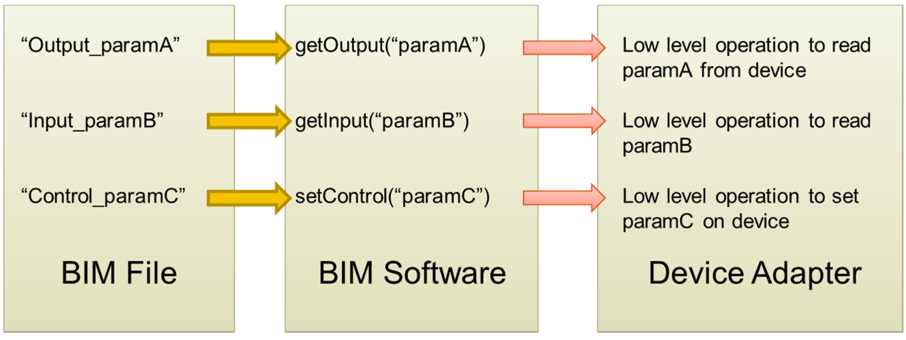
As different smart objects may have different data input/output interfaces, the properties parameter specified in our BIM design in the previous section provides a convenient way for the BIM tool to handle such low-level operations. An adapter layer is designed in this research to process the requests from BIM software, which parses the IFC file and demands data exchange for the smart object. The mapping/parsing operation is illustrated in
Figure 8. The software architecture for our developed BIM tool is shown in
Figure 9.
Figure 8.
Mapping from the BIM file to the software information interface programming.
Figure 8.
Mapping from the BIM file to the software information interface programming.
Figure 9.
BIM-based energy management platform software architecture. DER, distributed energy resource.
Figure 9.
BIM-based energy management platform software architecture. DER, distributed energy resource.
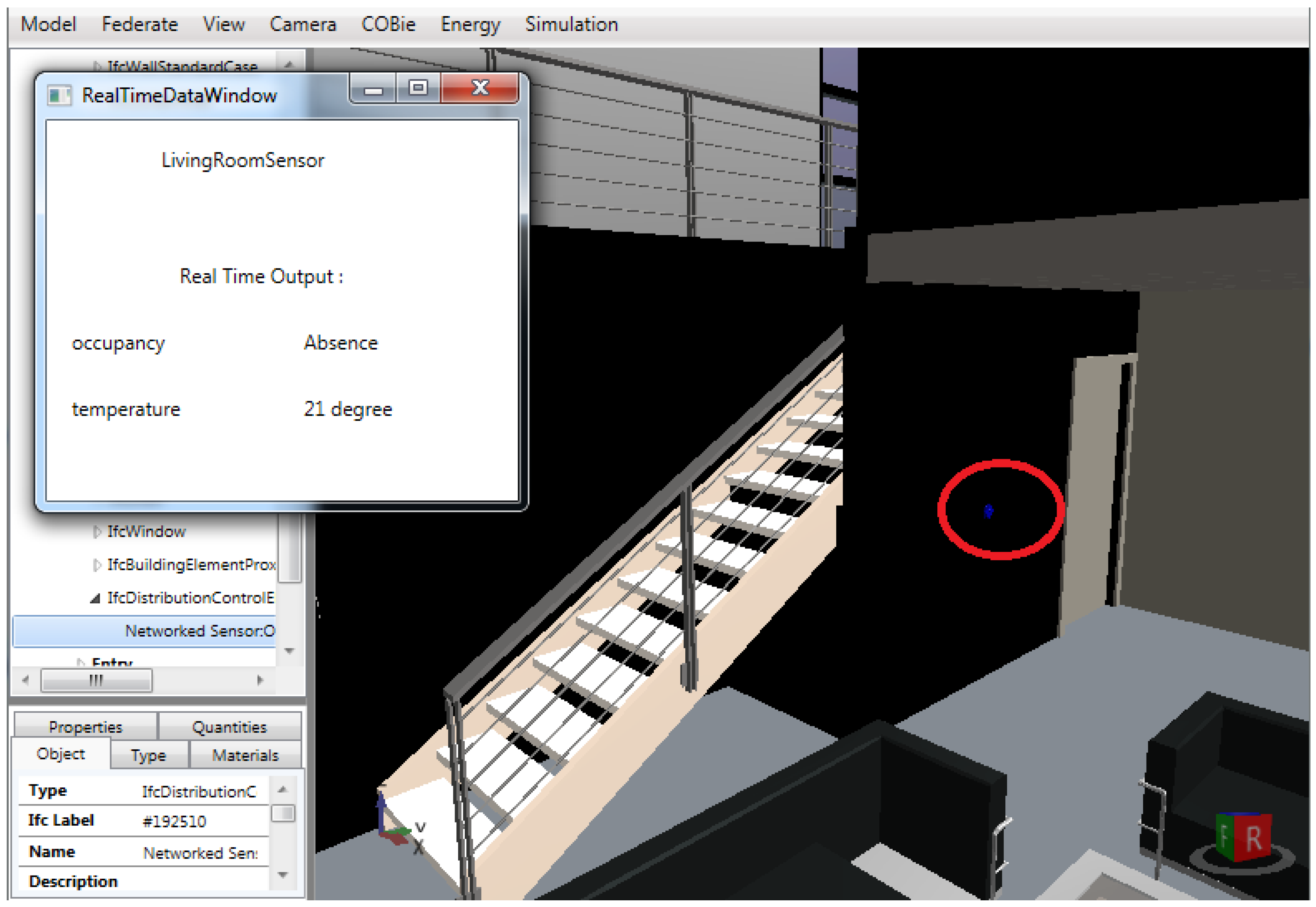
Real-time data from the DERs, smart meters and sensors are collected and stored in a database.
Figure 10 shows an instance of the real-time monitoring data from a living room sensor displayed to the user,
i.e., home owner or building manager.
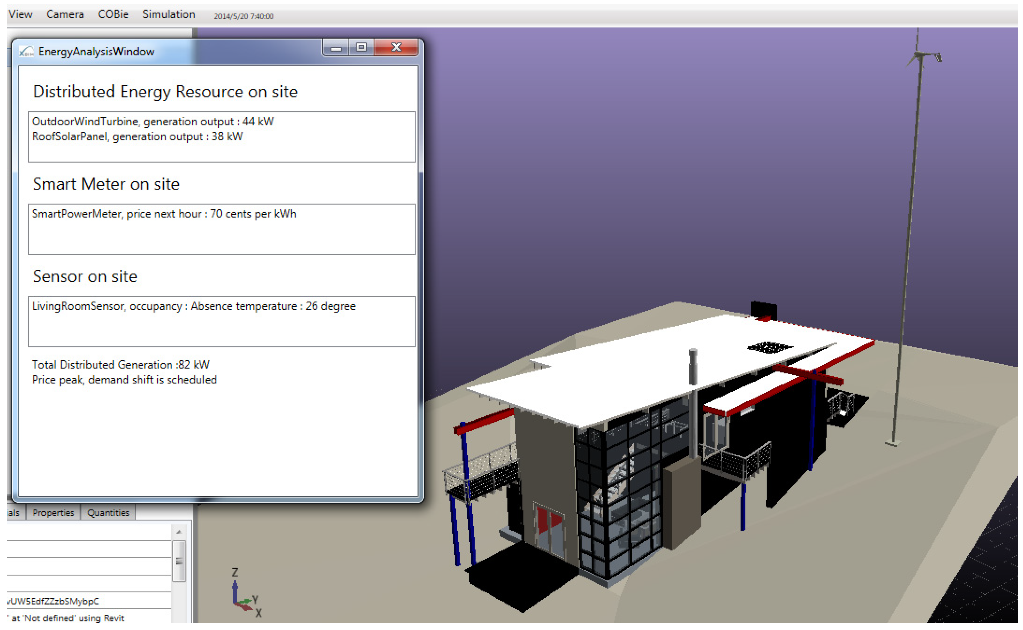
With real-time data from the smart objects, energy management and analysis in BIM software are facilitated and achieved. Real-time generation data of on-site DERs show the current energy production capacity and indicate how many loads can be supplied off the power grid. Weather, temperature, building and occupant data from sensors form a view of the present and future energy generation/consumption, as shown in
Figure 11. The pricing information from the smart meter allows the building to perform demand response actions in coordination with the power grid.
Figure 10.
Real-time monitoring data display to the user.
Figure 10.
Real-time monitoring data display to the user.
Figure 11.
Energy analysis functionality in smart built environment.
Figure 11.
Energy analysis functionality in smart built environment.
In our BIM tool, we demonstrated the energy management functionality through a simulation of demand shifting. When the real-time pricing information from the smart meter reaches a user-defined threshold, the software triggers the demand shift process and transmits control commands to the energy-consuming appliances.
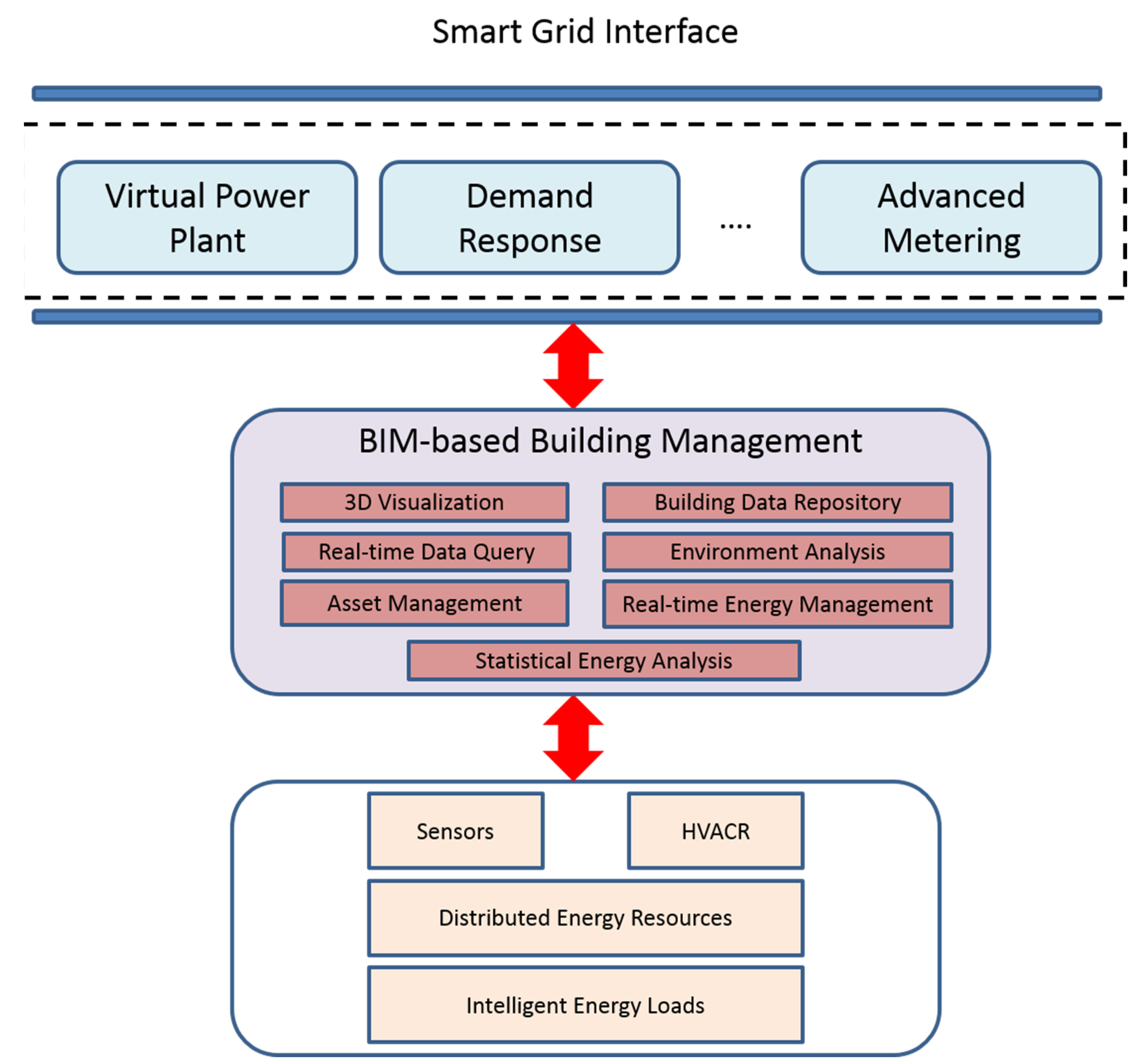
As future work, we are working towards an advanced BIM-based building management platform for smart buildings to host smart grid services and applications, such as virtual power plant and demand response, as shown in
Figure 12.
Figure 12.
Proposed BIM-based building management for a smart grid.
Figure 12.
Proposed BIM-based building management for a smart grid.
6. Conclusions
In this paper, the findings and experiences gained from an investigation into how BIM can be developed and utilized for smart built environments are reported. Our work covers the investigation of BIM-based methodologies for pre-construction design and verification and post-construction facility management of smart built environments in the smart grid era. A basic, but functional, prototype of a smart house energy management system using Revit and the xBIM toolkit was also implemented and successfully demonstrated. We are currently extending our work to develop BIM software tools for automated management of BACnet-compliant HVACR (Heating, Ventilating, Air Conditioning and Refrigeration) systems and investigating the information fusion and decision system of smart grid applications for future smart-powered buildings.
Acknowledgments
This work has been supported in part by a research assistantship grant from Auckland University of Technology for Jianchao Zhang. The authors would also like to thank Andrew Douglas for facilitating the access to the software resources used in this research.
Author Contributions
The topic and scope of this research were originally defined in a research proposal by Boon-Chong Seet and Tek Tjing Lie on BIM for smart-powered buildings. Jianchao Zhang conducted the research and implemented the proposed solutions under the supervision of Boon-Chong Seet and Tek Tjing Lie, who contributed their expertise on smart environments and smart grids, respectively. The paper was drafted by Jianchao Zhang and revised by Boon-Chong Seet.
Conflicts of Interest
The authors declare no conflict of interest.
References
- Sabol, L. Building Information Modelling and Facility Management. In Proceedings of the IFMA World Workplace, Dallas, TX, USA, 15–17 October 2008.
- Teicholz, P. BIM for Facility Managers; John Wiley & Sons: Hoboken, NJ, USA, 2013; p. 332. [Google Scholar]
- Talebi, S. Rethinking the Project Development Process through Use of BIM. In Proceedings of the 2nd BIM International Conference on Challenges to Overcome, Lisbon, Portugal, 9–10 October 2014.
- Nakashima, H.; Aghajan, H.K.; Augusto, J.C. Handbook of Ambient Intelligence and Smart Environments; Springer: New York, NY, USA, 2010; p. 1293. [Google Scholar]
- International Energy Agency. Sustainable Buildings. Available online: http://www.iea.org/topics/energyefficiency/subtopics/sustainablebuildings/ (accessed on 30 November 2014).
- Van der Meer, S.; Jennings, B.; Barrett, K.; Carroll, R. Design Principles for Smart Space Management. In Proceedings of the 1st International Workshop on Managing Ubiquitous Communications and Services (MUCS), M-Zones Whitepaper, Waterford, Ireland, 11 December 2003.
- Umakoshi, K.; Kambayashi, T.; Yoshida, M.; Takemoto, M.; Matsuo, M. S^3: Smart Shadow System for Real World Service and Its Evaluation with Users. In Proceedings of the IEEE/IPSJ 11th International Symposium on Applications and the Internet (SAINT), Munich, Germany, 18–21 July 2011.
- Dong, J.S.; Feng, Y.; Sun, J. Sensor Based Designs for Smart Space; Technical Report; Computer Science Department, National University of Singapore: Singapore, 2004. [Google Scholar]
- Inada, T.; Igaki, H.; Ikegami, K. Detecting service chains and feature interactions in sensor-driven home network services. Sensors 2012, 12, 8447–8464. [Google Scholar] [CrossRef] [PubMed]
- Guinard, A.; McGibney, A.; Pesch, D. A Wireless Sensor Network Design Tool to Support Building Energy Management. In Proceedings of the First ACM Workshop on Embedded Sensing Systems for Energy-Efficiency in Buildings, Berkeley, CA, USA, 4–6 November 2009.
- Jeng, T. Toward a ubiquitous smart space design framework. J. Inf. Sci. Eng. 2009, 25, 675–686. [Google Scholar]
- Bhatt, M.; Dylla, F.; Hois, J. Spatio-Terminological Inference for the Design of Ambient Environments. In Spatial Information Theory; Springer: Berlin, Germany, 2009; pp. 371–391. [Google Scholar]
- Becerik-Gerber, B.; Jazizadeh, F.; Li, N.; Calis, G. Application areas and data requirements for BIM-enabled facilities management. J. Constr. Eng. Manag. 2011, 138, 431–442. [Google Scholar] [CrossRef]
- Attar, R.; Hailemariam, E.; Glueck, M.; Tessier, A.; McCrae, J.; Khan, A. BIM-Based Building Performance Monitor. In Proceedings of the SimAUD Conference, Symposium on Simulation for Architecture and Urban Design, Orlando, FL, USA, 12–15 April 2010.
- Onuma. Onuma System. Available online: http://onuma.com/products/OnumaPlanningSystem.php (accessed on 30 November 2014).
- Lavelle, M.R.; Onuma, K. Virtual Real Time Information System: Moving to Cloud-Based Building Management. Available online: http://www.lavelleenergy.com/index.php/component/content/article/all-buildings/86-virtual-realtime-information-system (accessed on 30 November 2014).
- Arnold, G.W. Challenges and opportunities in smart grid: A position article. Proc. IEEE 2011, 99, 922–927. [Google Scholar] [CrossRef]
- East, B. Construction-Operations Building Information Exchange (COBie). Available online: http://www.wbdg.org/resources/cobie.php (accessed on 30 November 2014).
- Park, S.O.; Park, J.H.; Jeong, Y.S. An efficient dynamic integration middleware for cyber-physical systems in mobile environments. Mob. Netw. Appl. 2013, 18, 110–115. [Google Scholar] [CrossRef]
- Autodesk. Placing Sensors in the Revit Model. Available online: http://www.digital210king.org/blog.php?p=30 (accessed 30 November 2014).
- Resendes, S.; Carreira, P.; Santos, A.C. Conflict detection and resolution in home and building automation systems: A literature review. J. Ambient Intell. Humaniz. Comput. 2014, 5, 699–715. [Google Scholar] [CrossRef]
- Marza, A.O.; Avram, I.M.; Tamovan, I.G. An Analysis of Target Materials Influence on Optical Sensors Performance. In Proceedings of the IEEE International Conference and Exposition on Electrical and Power Engineering (EPE), 25–27 October 2012; pp. 85–87.
- The xBIM Toolkit. Available online: http://xbim.codeplex.com/ (accessed on 30 November 2014).
© 2015 by the authors; licensee MDPI, Basel, Switzerland. This article is an open access article distributed under the terms and conditions of the Creative Commons Attribution license (http://creativecommons.org/licenses/by/4.0/).


