1. Introduction
Curved surface shell structures can be used to create very useful, lightweight, rigid structural forms. This paper looks at just one technique of producing shell structures, utilising bent strips of sheet material such as steel plate or plywood, joined together into rigid tubes or shells.
Sheet materials can only be bent/curved in particular ways, essentially limited to the surfaces of cylinders and cones, or combinations of various sized cylinders and cones (i.e., surfaces with zero Gaussian curvature).
What is not generally practical is deforming sheet materials into doubly-curved spherical (synclastic) or saddle-shaped/twisted (anticlastic) shapes, as these require plastic deformation possible only by applying large forces and/or heat.
So what we need is what are called developable surfaces, or rather, shapes that can be assembled from more than one developable surface. A developable surface is a shape that can be formed by simple bending of a sheet material without any twisting or other plastic deformation of the material.
At first glance it is not entirely obvious how complex shapes can be created that consist of more than one developable surface. This paper introduces five related techniques for generating such surfaces that allow a vast variety of previously impractical shapes to be produced.
Most approaches to this problem to date have been to generate doubly-curved shapes with tools such as NURBS patches and then attempt to find developable surfaces that approximate these shapes. This paper introduces a productive technique that works by limiting the range of doubly-curved shapes to a subset that can be simply broken down into developable surfaces. This limitation is that the surfaces are rulings between pairs of carefully constructed splines rather than free-form NURBS patches.
2. Previous Work
Developable surfaces are a powerful geometrical technique for assembling curved structures from sheet materials, perhaps best known through the practice of the architect Frank Gehry [
1] and the curved cladding systems used in their buildings.
The computer scientist Dr. David Huffman was a pioneer of techniques for curved folding of sheet materials to result in developable curved surfaces. Note that although fascinating mathematically, the requirement for both sides of the fold to belong to the same planar sheet is not that interesting for large scale structural design. There have been developments of these techniques [
2] using computer simulations to devise quite intricate and beautiful three dimensional shapes.
Other useful techniques are a subdivision approach to devise curved developable surfaces from coarse planar quadrilateral meshes [
3], a technique for fitting developable singly curved strips to arbitrary free-form surfaces [
4], and fitting small single and double curved panels to arbitrary free-form surfaces [
5]. The textbook
Architectural Geometry [
6] contains a general summary of many of these techniques.
A technique with many similarities to those described in this paper is the process of Schlaich, Bergermann and Partners for the creation of
scale-trans-surfaces, described by Shelden [
1]. Here a
directrix line is used to loft a
generatrix line, with a
scaling law applied to modify the curve along the loft. This produces surfaces equivalent to method four below, somewhat complicated by the need for the
scaling law abstraction.
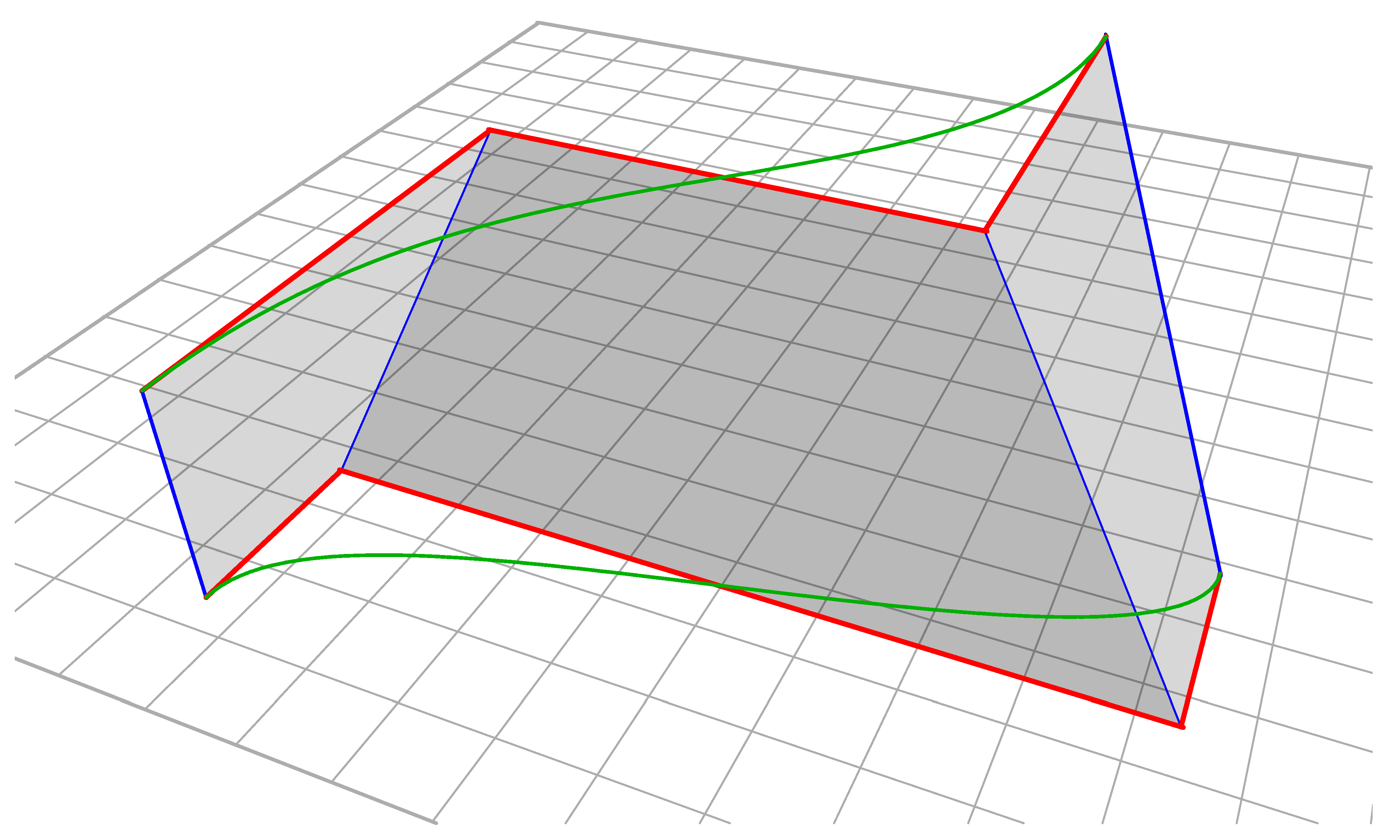
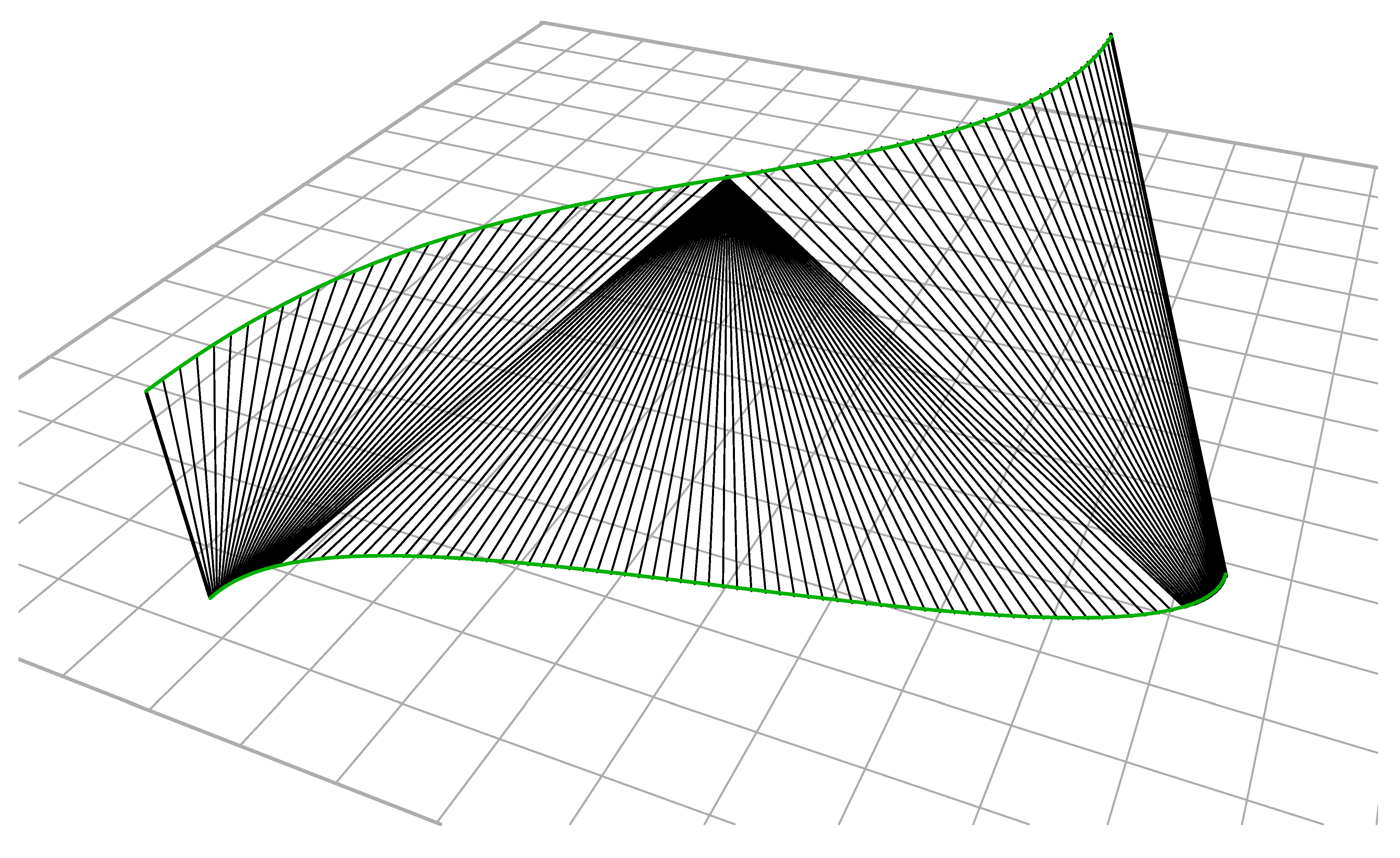
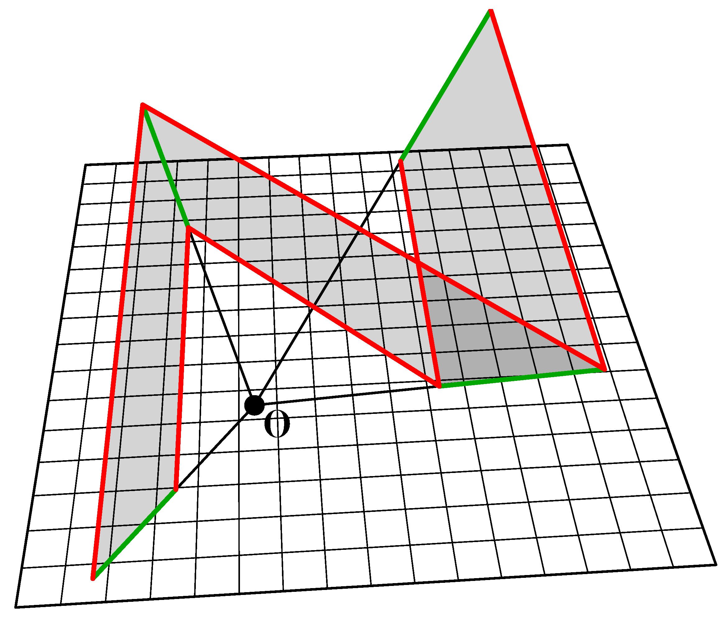
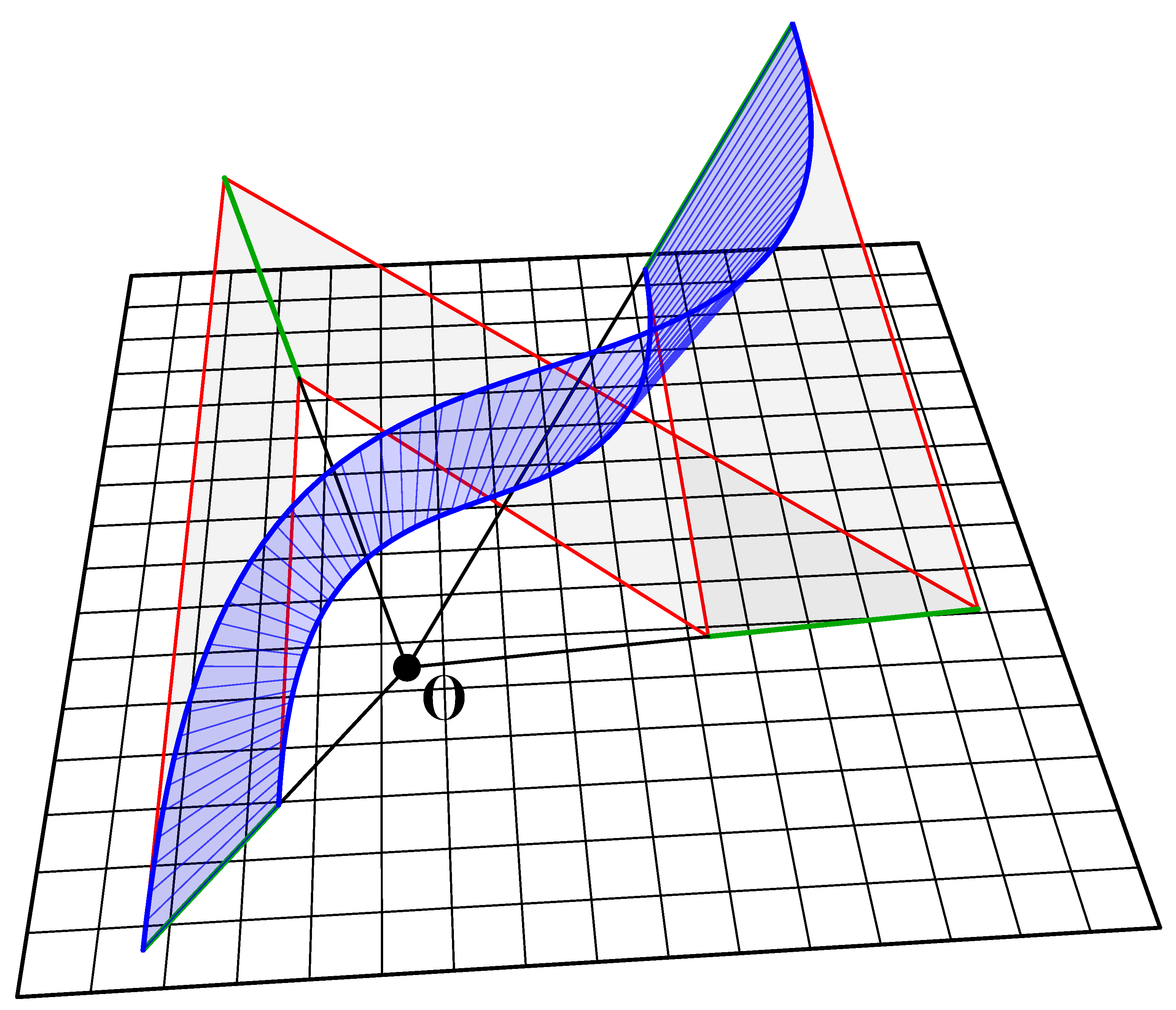
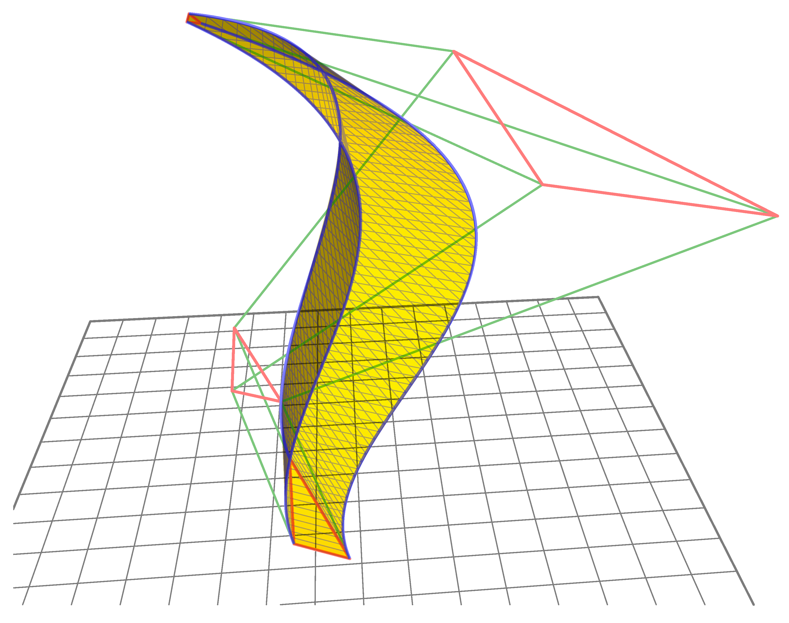
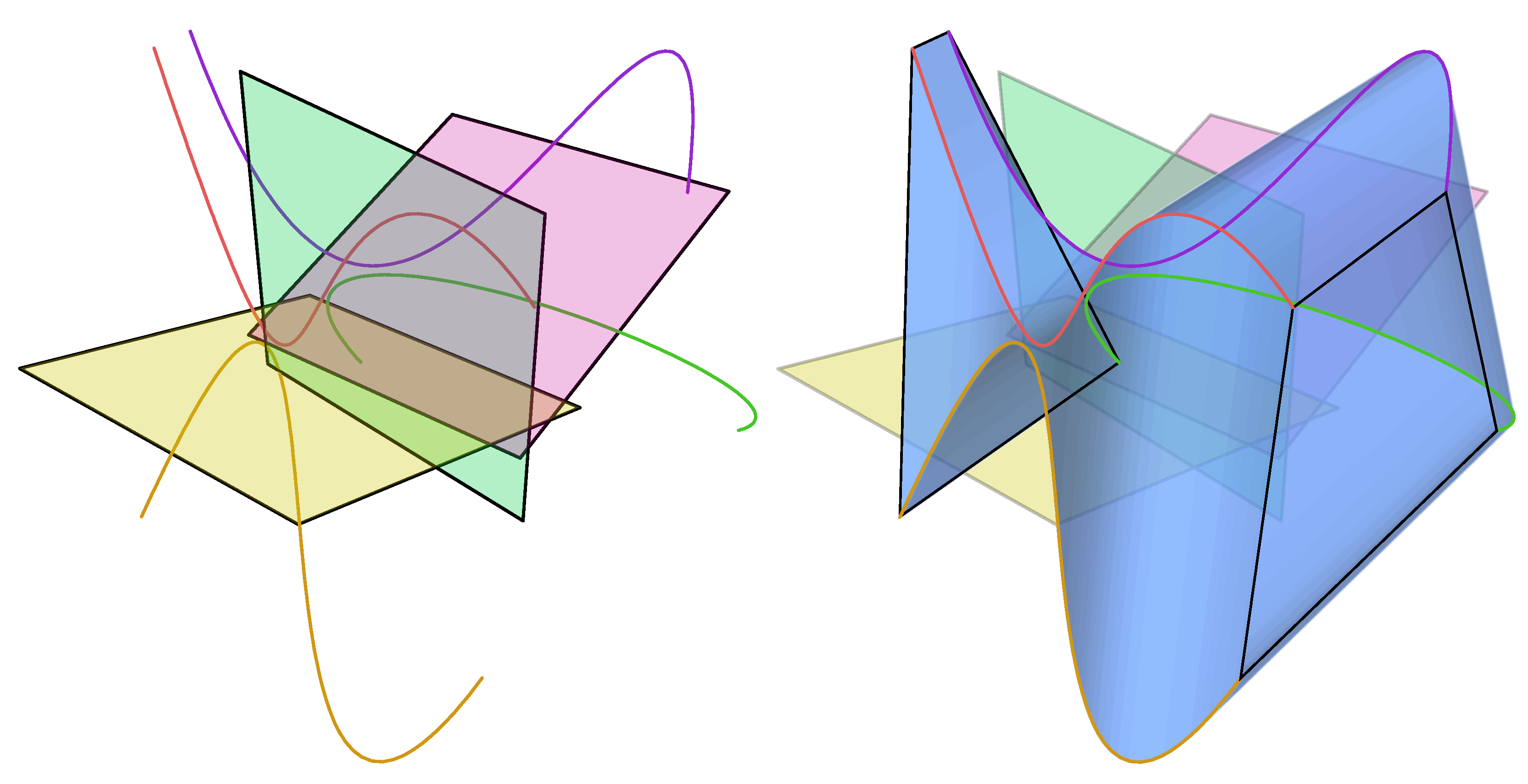
The method for creating developable surfaces explored here is to rule a surface between two splines; however, not all pairs of splines have a practical developable solution. One method of forcing a developable solution is to construct splines using the edges of a series of linked planar quadrilaterals. So long as each quadrilateral is planar, the established theory, as described by Shelden, is that a developable surface can be generated between them. However, even with these constraints, a simple three quadrilateral geometry can be constructed that can only be developed by introducing ugly singularities (
Figure 2).
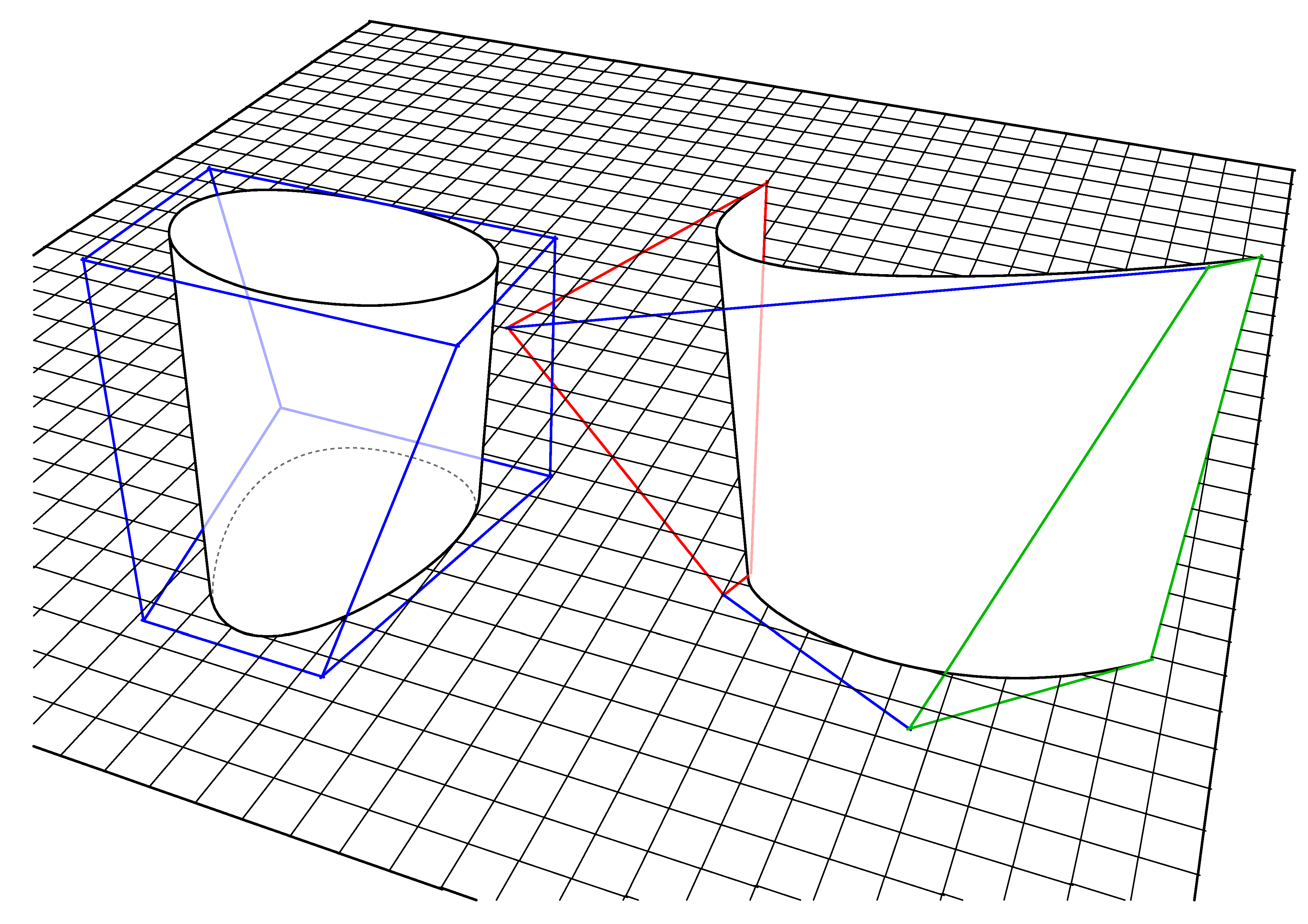
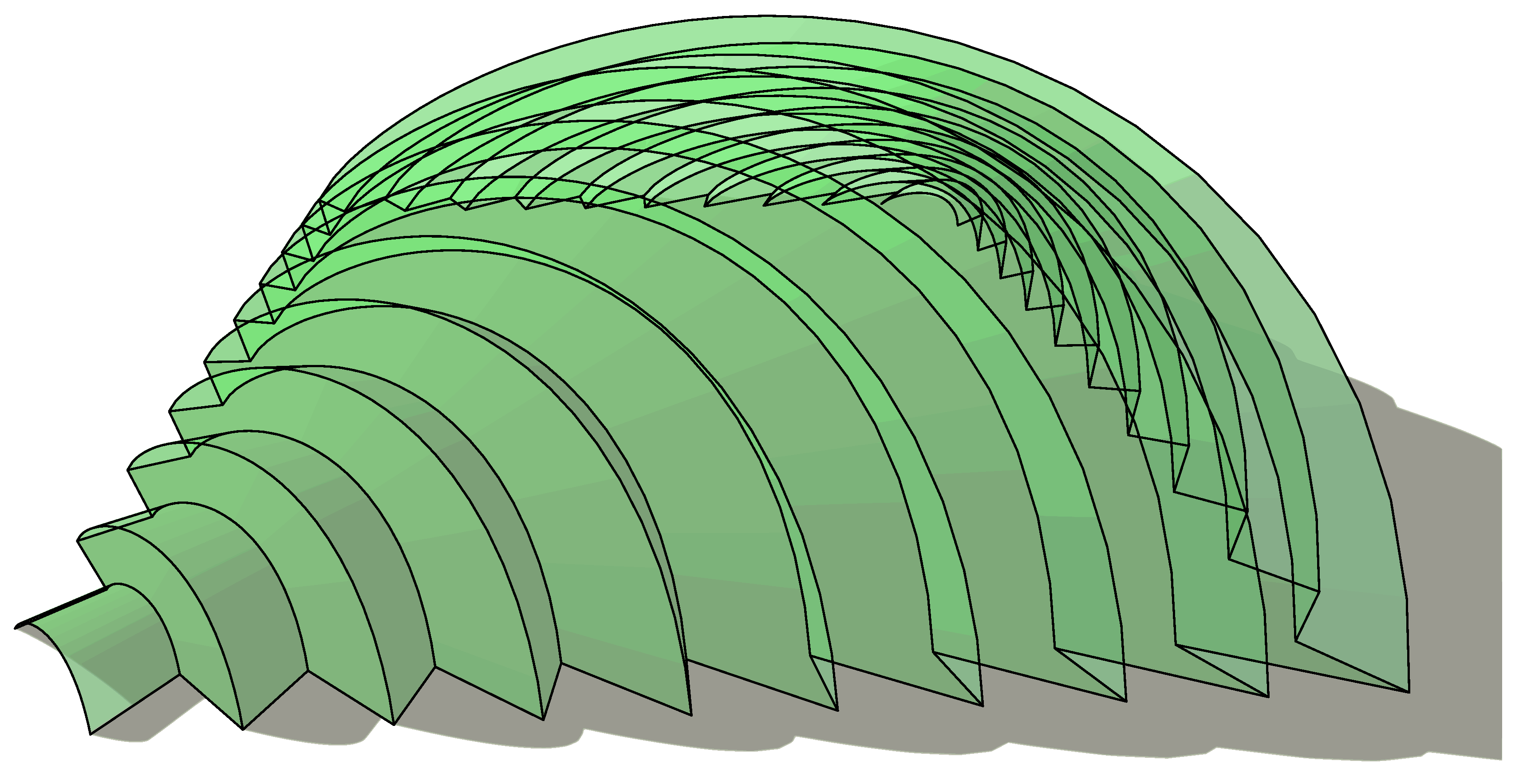
A more general form of this theory is that many, but not all, pairs of splines can be ruled if the
end quadrilaterals are planar. The subset of these splines that are also convex ‘C’ shaped rather than ‘S’ shaped can
always be developed, as can all ‘O’ shaped closed splines that are continuously convex, see
Figure 3 and
Figure 4.
Figure 1.
Two ‘S’ shaped splines constructed using edges of three connected planar quadrilaterals. Note that the two splines are not in the same plane and indeed that they need not even be planar.
Figure 1.
Two ‘S’ shaped splines constructed using edges of three connected planar quadrilaterals. Note that the two splines are not in the same plane and indeed that they need not even be planar.
Figure 2.
Attempting to create a developable surface from two ‘S’ shaped splines above, this surface can only be made developable by introducing the radial singularity shown at the top-middle.
Figure 2.
Attempting to create a developable surface from two ‘S’ shaped splines above, this surface can only be made developable by introducing the radial singularity shown at the top-middle.
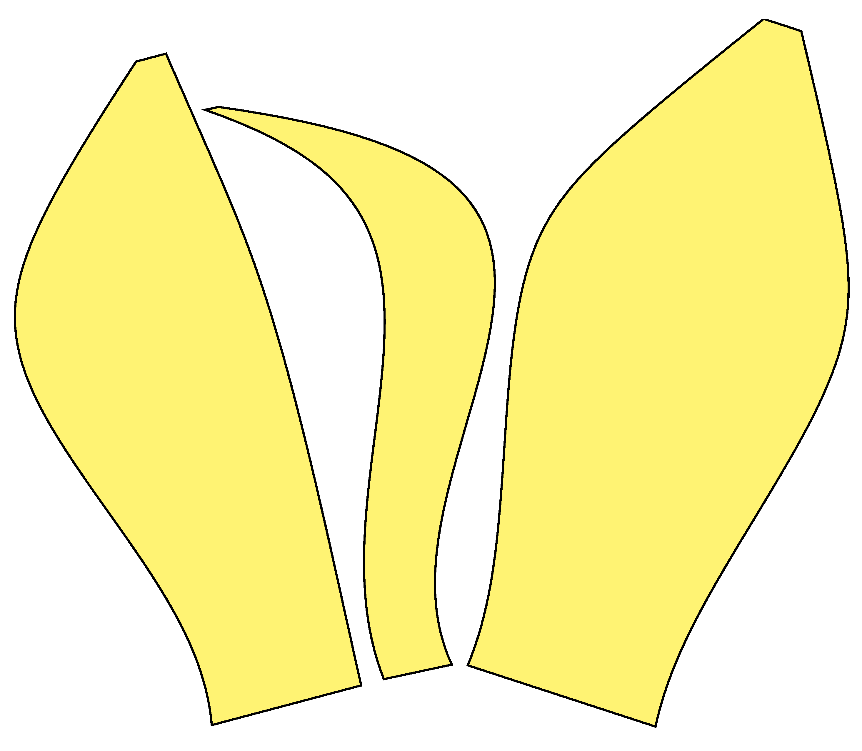
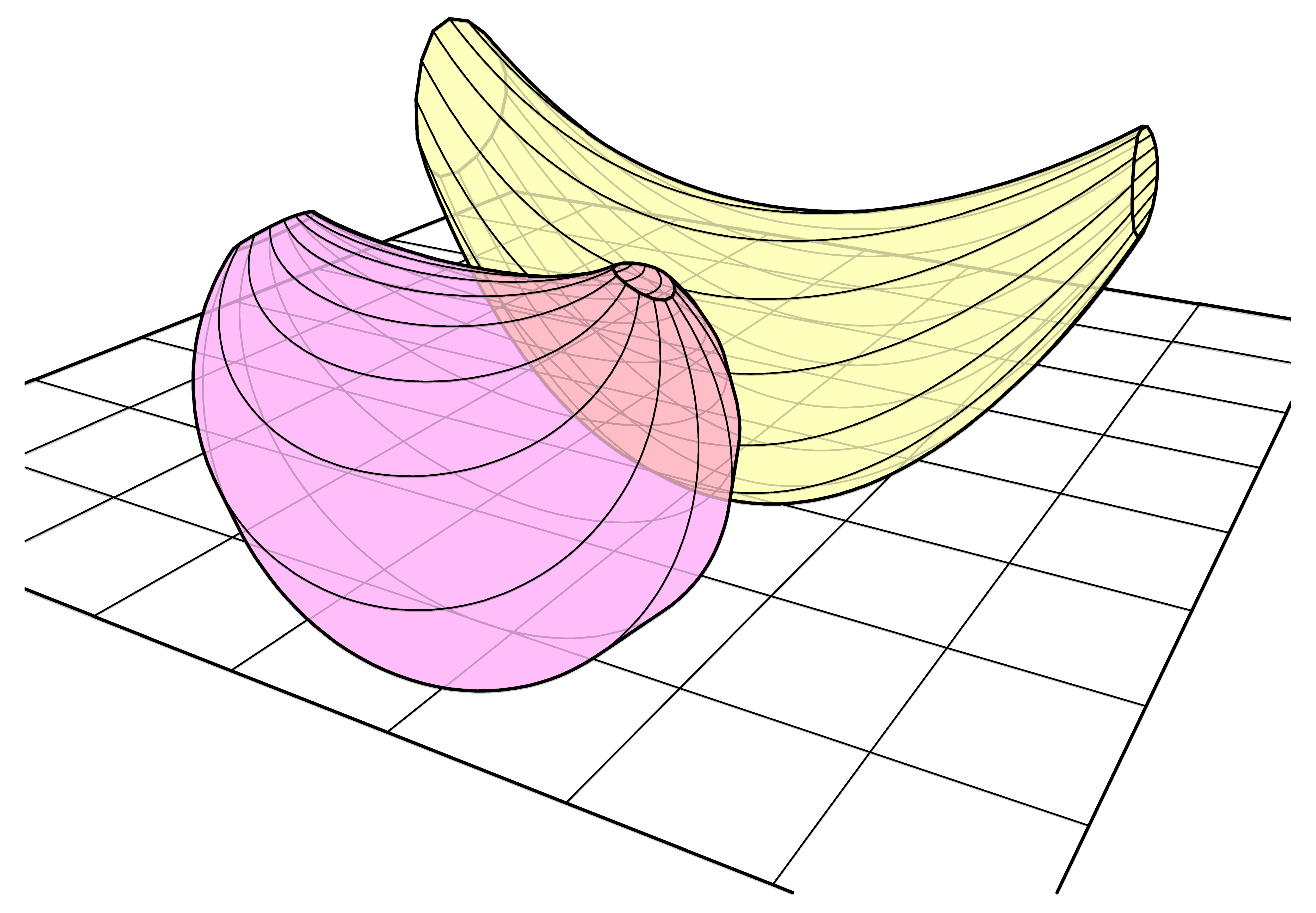
Figure 3.
‘C’ and ‘O’ shaped simple developable surfaces and their construction. The red and green quadrilaterals are each planar, however none of the blue quadrilaterals need to be planar in order to generate developable surfaces.
Figure 3.
‘C’ and ‘O’ shaped simple developable surfaces and their construction. The red and green quadrilaterals are each planar, however none of the blue quadrilaterals need to be planar in order to generate developable surfaces.
Figure 4.
‘C’ and ‘O’ shaped simple developable surfaces unrolled. Note that the ruling lines are irregular. They are neither radial nor parallel, but change direction constantly along the length.
Figure 4.
‘C’ and ‘O’ shaped simple developable surfaces unrolled. Note that the ruling lines are irregular. They are neither radial nor parallel, but change direction constantly along the length.
3. Triangles and Quadrilaterals
Typically, a developable surface is represented as a series of very slender triangles or planar quadrilaterals. The process of developing the surface is simply to measure each triangle/quadrilateral in turn and to redraw them on a two dimensional surface. This process is quite time-consuming, so it is usually performed in software.
Of course with a little bit of effort it is possible to demonstrate that any surface can be trivially deconstructed to triangles, but not all triangular surfaces are usefully developable. A series of alternating left-right triangles may only be developable by introducing creases. An example would be a simple corkscrew shape—this is of no use if we want a smooth surface. A series of left-left triangles produces a cone shape. This is nicely developable but the apex of the cone where all triangles meet is practically impossible to roll from a sheet material.
In practice, the only shapes that are usefully developable are those consisting of a series of planar quadrilaterals that share one or both of the following properties.
These two properties are central to the following five related methods.
4. Method One
Principle: Ruling between two edges that have a simple scale (homothetic) transformation relationship generates conical surfaces consisting of planar quadrilaterals with both parallel edges and intersecting creases.
For example, take a single line in three dimensional space, create a copy and scale it any amount, draw a quadrilateral between these two lines, as with
Figure 5.
Note that:
This quadrilateral is planar.
This quadrilateral has two parallel edges.
This quadrilateral has two edges that intersect at the origin of the scale transformation.
Figure 5.
Two parallel homothetic lines (red), scale origin, two radial edges (green) and resulting planar quadrilateral.
Figure 5.
Two parallel homothetic lines (red), scale origin, two radial edges (green) and resulting planar quadrilateral.
Now let us take a ‘polyline’ that consists of more than one segment, copy and scale as before, and draw quadrilaterals between each of the segments, as with
Figure 6. Note that the polyline does not itself need to be planar.
Figure 6.
Parallel homothetic polylines (red), scale origin, radial edges (green) and resulting three planar quadrilaterals.
Figure 6.
Parallel homothetic polylines (red), scale origin, radial edges (green) and resulting three planar quadrilaterals.
Note again that:
All quadrilaterals are planar.
Each quadrilateral has two parallel edges.
All remaining edges intersect at the origin of the scale transformation.
This is a developable surface.
Now the interesting bit, we draw two 3D Bezier splines of the same type and weight using the ‘polylines’ from before as guides,
Figure 7. Note that although they appear ‘curved’, in practice these ‘spline curves’ are just two identical but scaled polylines consisting of many straight lines. Filling the space between with quadrilaterals produces a developable curved surface. These surfaces constructed between
homothetic splines have been dubbed ‘scale-trans surfaces’ by Schlaich, Bergermann and Partners engineers [
1], though note that the primary curves do not actually need to be planar for the generated surface to be developable.
Figure 7.
Developable ruled surface between two homothetic spline curves.
Figure 7.
Developable ruled surface between two homothetic spline curves.
This surface is somewhat useful, but as a structural form it has no rigidity, so it has no strength unless the edges are supported.
The next step is to add a third scaled, but otherwise identical, homothetic curve. Note that it is possible to generate three ruled surfaces connecting these three edges, where each of these surfaces is in turn developable,
Figure 8. Moreover, together these three surfaces form a rigid tube with the curvature actually stiffening the walls.
Figure 8.
Three developable ruled surfaces between three homothetic spline curves.
Figure 8.
Three developable ruled surfaces between three homothetic spline curves.
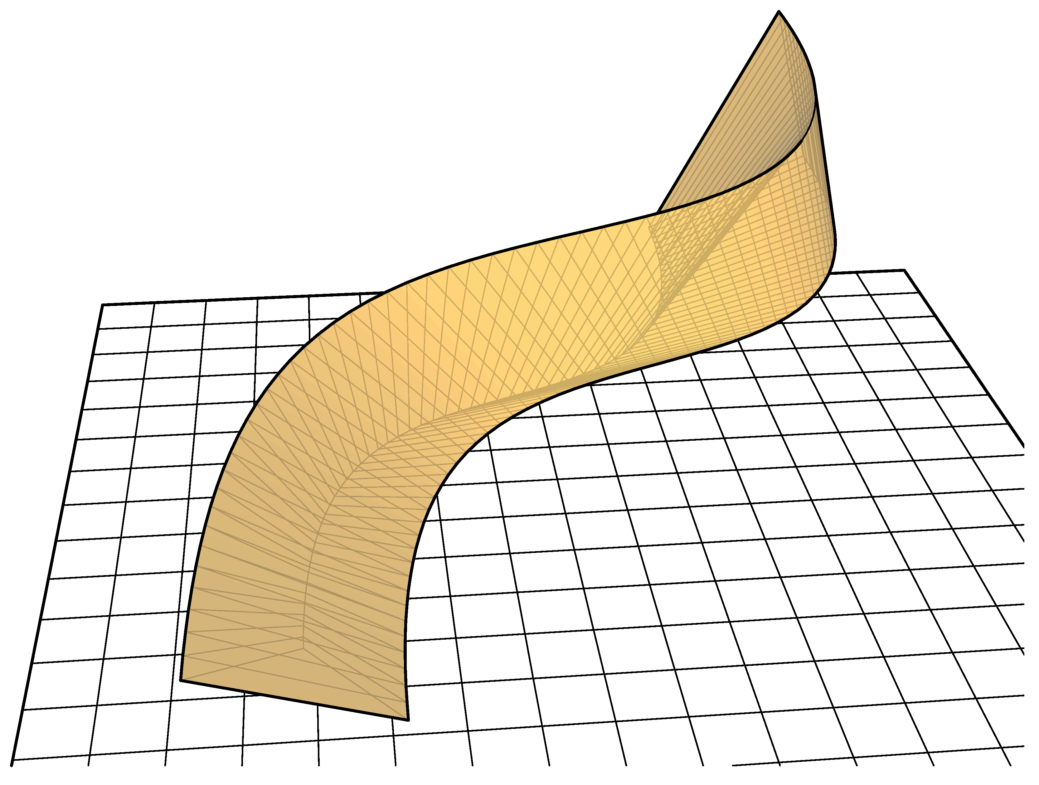
Figure 9.
Rigid tube consisting of three ruled surfaces between homothetic spline curves.
Figure 9.
Rigid tube consisting of three ruled surfaces between homothetic spline curves.
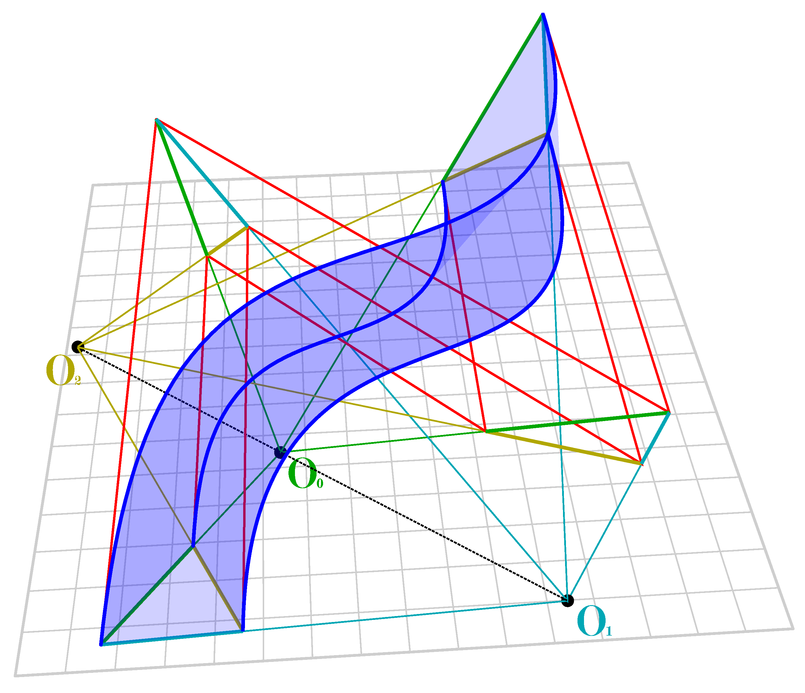
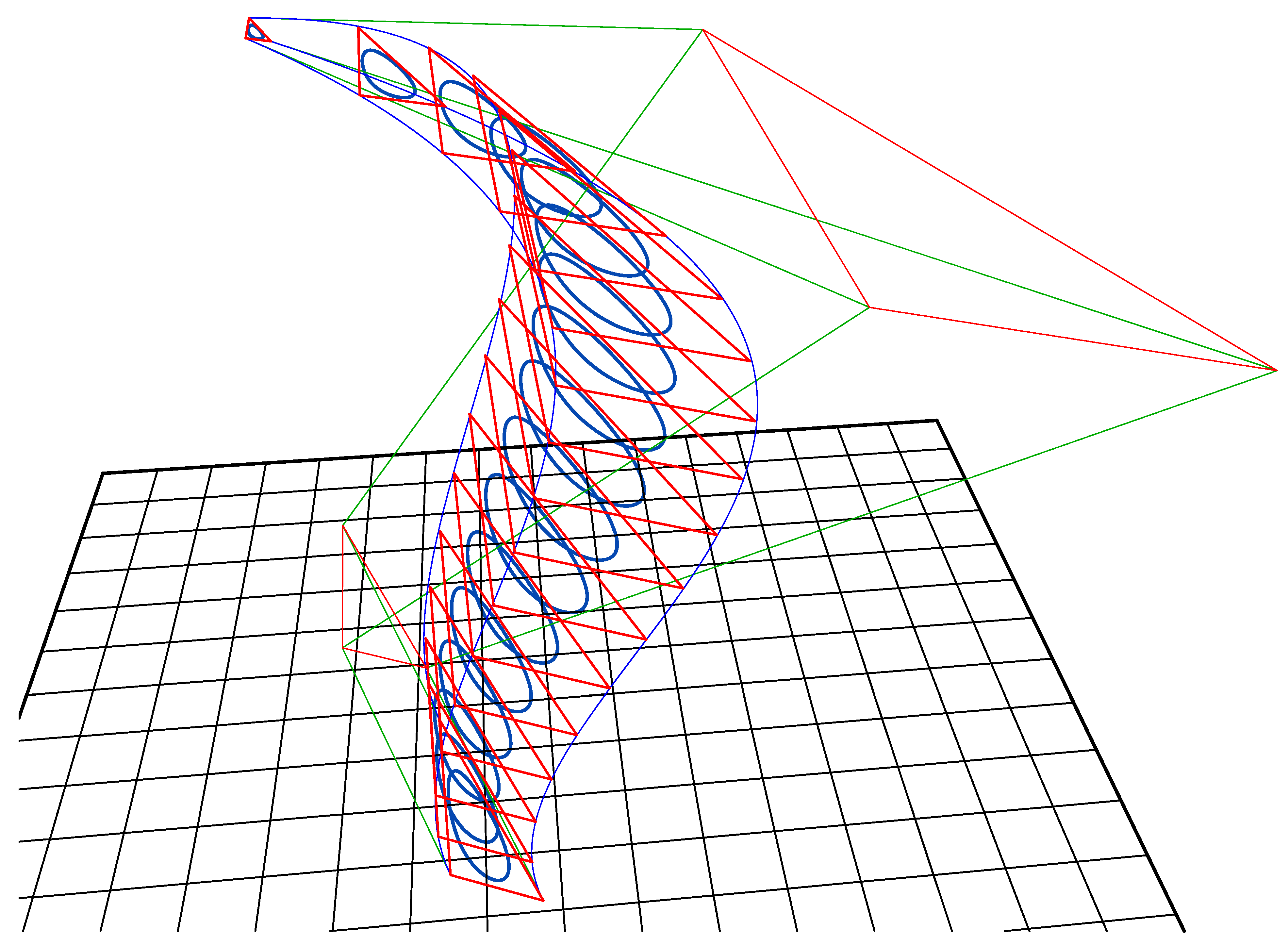
Note that the three origins O0, O1 and O2 of the three scale transformations form a straight line. This is important later when creating secondary shapes based on more than three primary surfaces where the origin-points need to be co-linear in order to generate planar crease lines, see method three below.
Note that with these ruled surfaces, the spacing of the quadrilaterals can be either equally spaced along the length, or can be based on the spline interpolation interval—which are otherwise generally not equivalent for any pair of spline curves. For the other methods (methods two, three and four) care must be taken not to equally rule the quadrilaterals along the length, as this cannot be guaranteed to generate developable surfaces.
Three edges can be used to generate a stiff tube (
Figure 9 and
Figure 10). Tubes can also be generated with more than three edges. See method four below for a technique to generate properly doubly-curved tubes and other shapes from more than three edges.
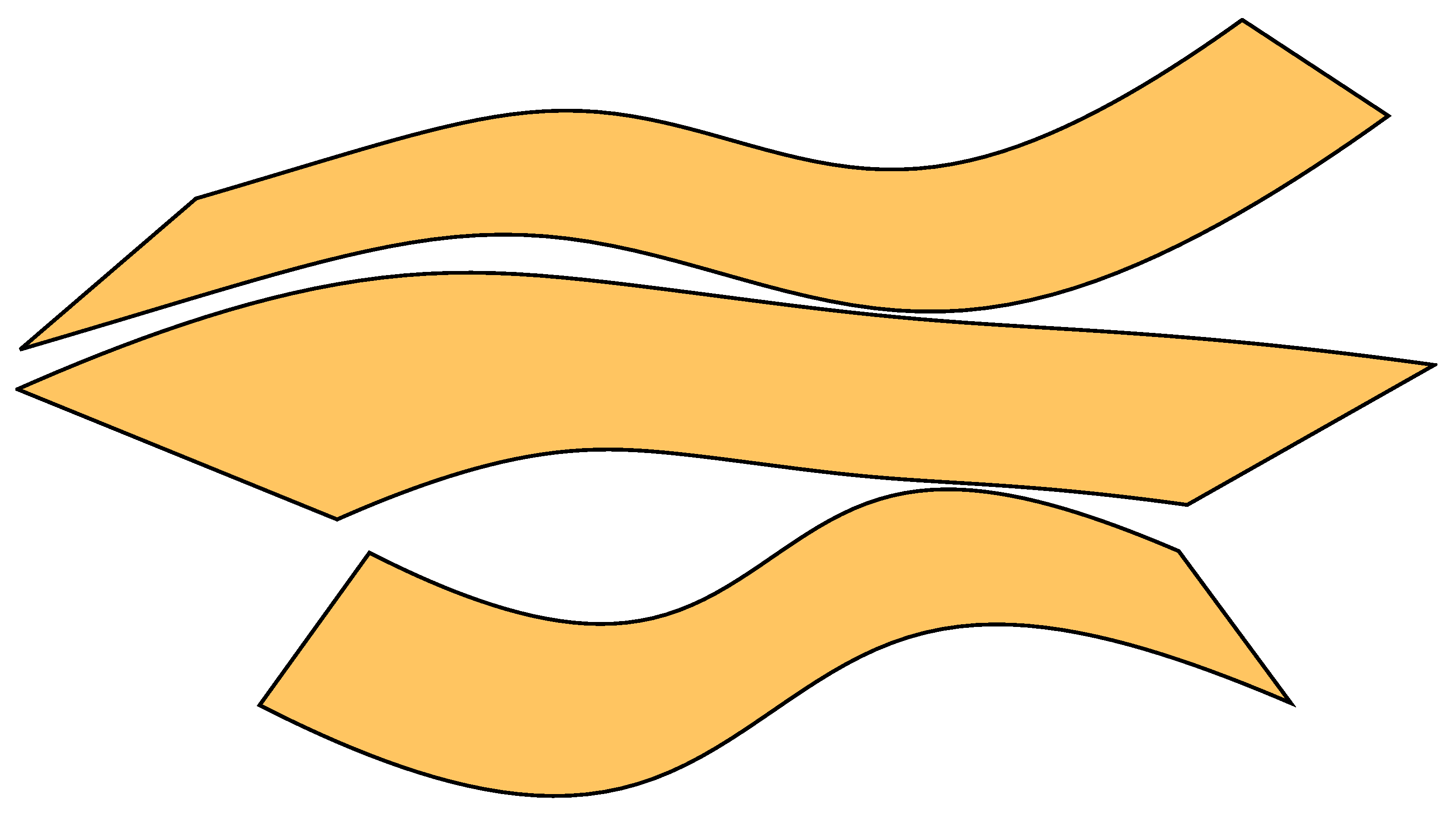
Figure 10.
Unrolled developed cutting pattern for rigid tube shown in
Figure 9.
Figure 10.
Unrolled developed cutting pattern for rigid tube shown in
Figure 9.
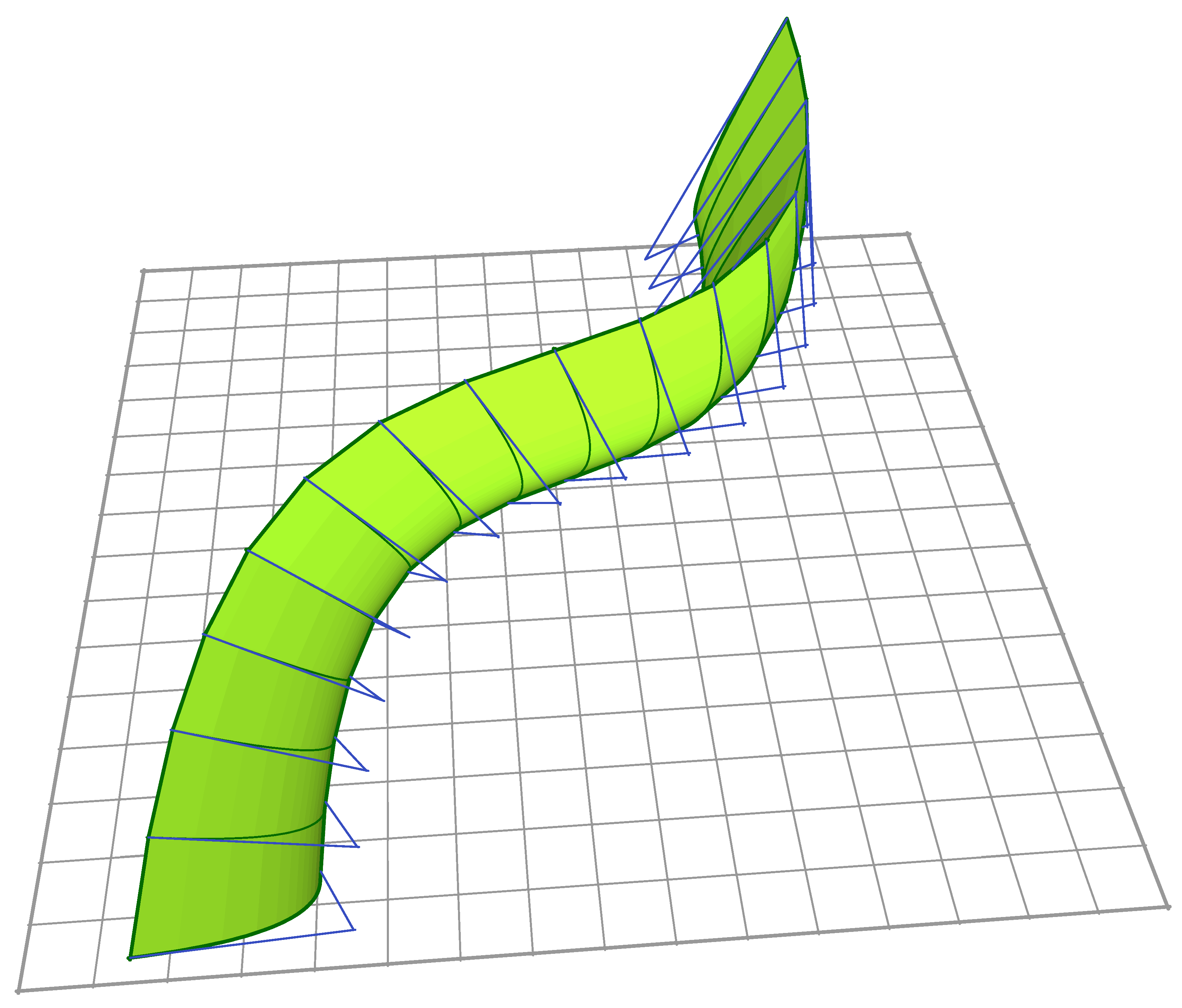
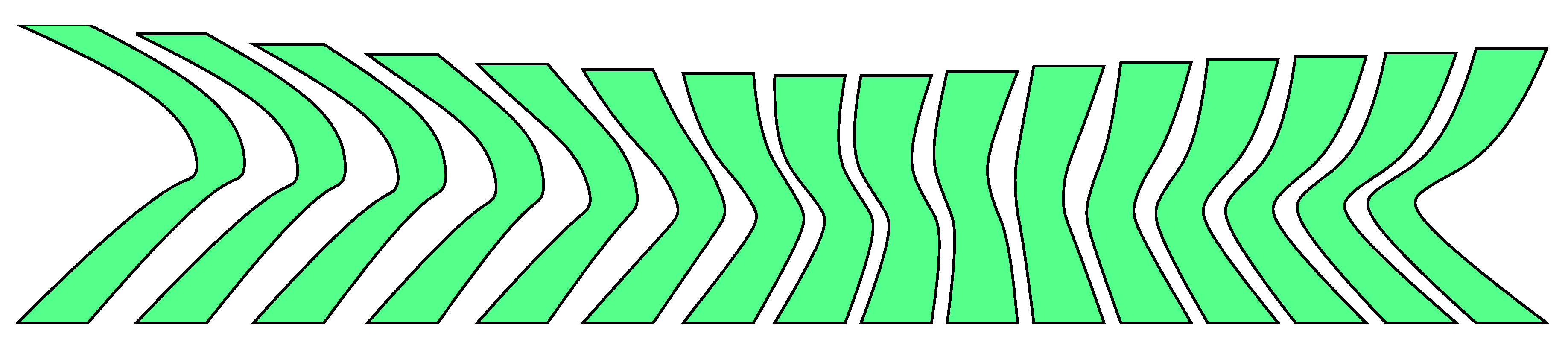
Alternatively, corrugated shells can be generated instead of doubly curved surfaces by alternating smaller and larger scaled versions of the primary shape and ruling between them (
Figure 11).
Figure 11.
A corrugated form of method one.
Figure 11.
A corrugated form of method one.
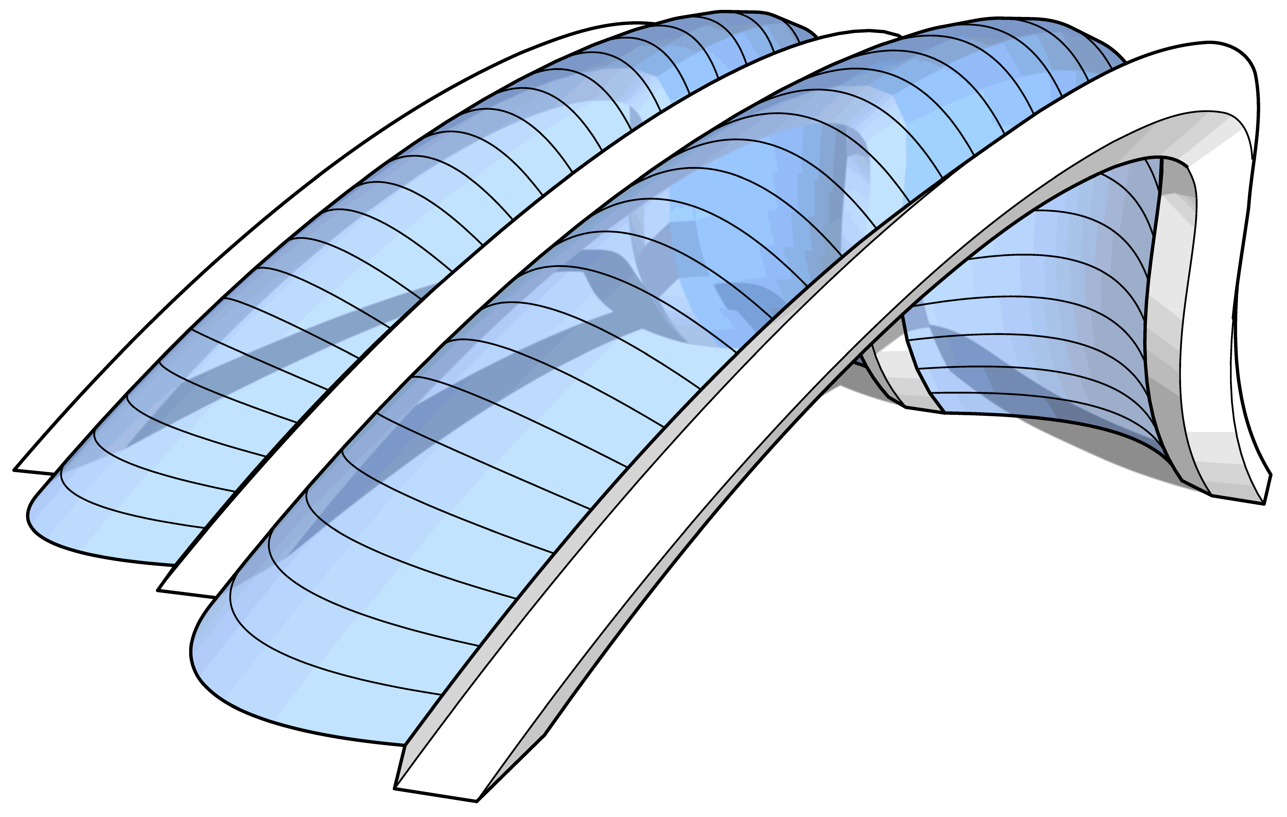
5. Method Two
Principle: Ruling between two edges where the ends form parallel lines generates cylindrical surfaces consisting of planar quadrilaterals with both parallel creases and intersecting edges.
This is an alternative to method one for generating primary singly curved shell surfaces. The results are closely related to the secondary surfaces generated by method three and have similar properties.
Imagine a series of polylines with a scale relationship as with method one, but instead of using these lines to generate a surface directly, add spline curves of the same type and weight using the nodes of these lines perpendicular to the primary polylines, a similar technique to that used in method three.
Figure 12.
Scaled homothetic polylines (red) and splines drawn between nodes (blue).
Figure 12.
Scaled homothetic polylines (red) and splines drawn between nodes (blue).
Unlike method one, none of these splines are scaled homothetic copies of each other. However they have a separate very useful property—any pair of these splines is coincident in two dimensions, with variation in only the third dimension. Taking a plane perpendicular to the construction lines connecting each pair of splines, and projecting those splines onto that plane, the splines will be coincident. This is because the interpolated coordinates of a spline are independent for each orthogonal direction regardless of any rotation of the coordinate space.
This means that we can draw a ruled surface between any two secondary splines and form a cylindrical developable surface, i.e., all quadrilaterals in this surface have parallel edges. Note that cylindrical developable surfaces are more straightforward to shape in the workshop than conical surfaces.
Figure 13.
Ruled surfaces between splines drawn between homothetic polylines.
Figure 13.
Ruled surfaces between splines drawn between homothetic polylines.
Figure 14.
Developed surfaces created using method two, note that the ends of each panel are parallel.
Figure 14.
Developed surfaces created using method two, note that the ends of each panel are parallel.
The other important consideration is that it is not possible to rule this surface by equally spacing along the spline length, since the spline has variation in the third dimension and so does not have a simple relationship between length and the subdivision interpolation points, as would be the case with homothetic splines. The ruling needs to be constructed using the spline subdivision interpolation points, since with these the two dimensional location in the perpendicular plane is independent of any additional variation outside the plane.
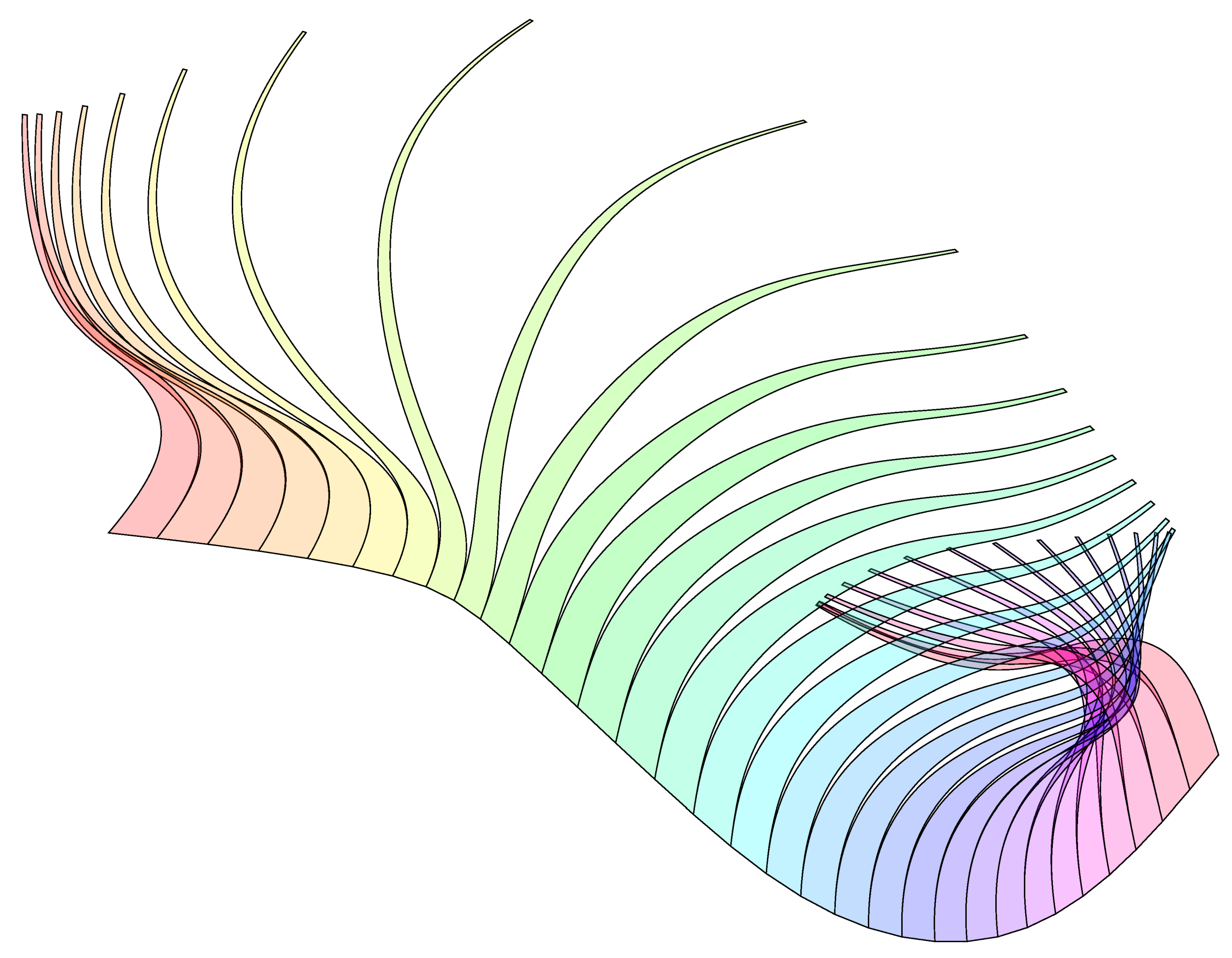
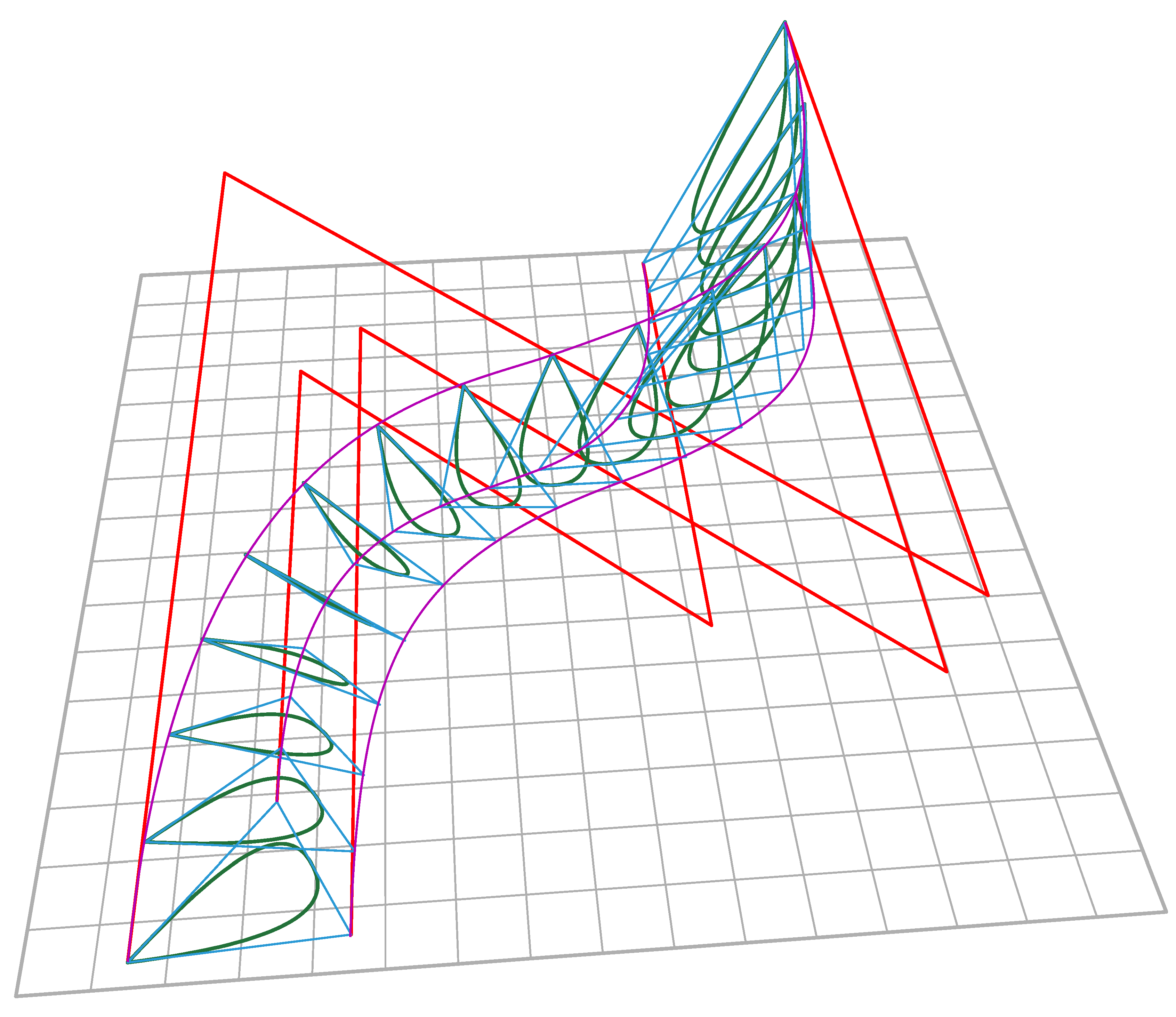
6. Method Three
Principle: ruling between splines constructed on primary conical surface geometry created by method one produces secondary cylindrical geometry as described in method two.
This method utilises a multi-surface shape generated by method one and uses it to generate a series of secondary surfaces, each of which fully developable. The resulting compound surface is effectively doubly-curved and forms a rigid shell.
So take a surface generated using the first technique, either with quadrilaterals ruled by equal subdivision or with quadrilaterals ruled by spline interpolation, though the first ruling type produces aesthetically better shapes. Use the ruled edges to draw a secondary set of splines perpendicular to the splines created in the first instance (
Figure 15).
Figure 15.
Homothetic splines (magenta) and their regular division into secondary geometry (blue). These create a secondary set of splines (green).
Figure 15.
Homothetic splines (magenta) and their regular division into secondary geometry (blue). These create a secondary set of splines (green).
Note that none of these secondary splines are scaled copies of each other as with method one above, but they are coincident in two dimensions since the control points are placed on parallel lines.
This means we can rule developable surfaces between them so long as we use the spline interpolation points for the ruling. The surfaces as shown in
Figure 16 and
Figure 17 are cylindrical developable surfaces as described in method two.
Figure 16.
Developable surfaces created from geometry shown above, using method three.
Figure 16.
Developable surfaces created from geometry shown above, using method three.
Figure 17.
Developed surfaces created using method three.
Figure 17.
Developed surfaces created using method three.
Note that with three primary splines these secondary splines will be planar, whereas with more than three primary splines the secondary splines will only be planar if the origin-points of the initial scale transformations are co-linear. If the secondary splines are planar, then these can be used for internal/external baffles/bulkheads if additional structural stiffening is required.
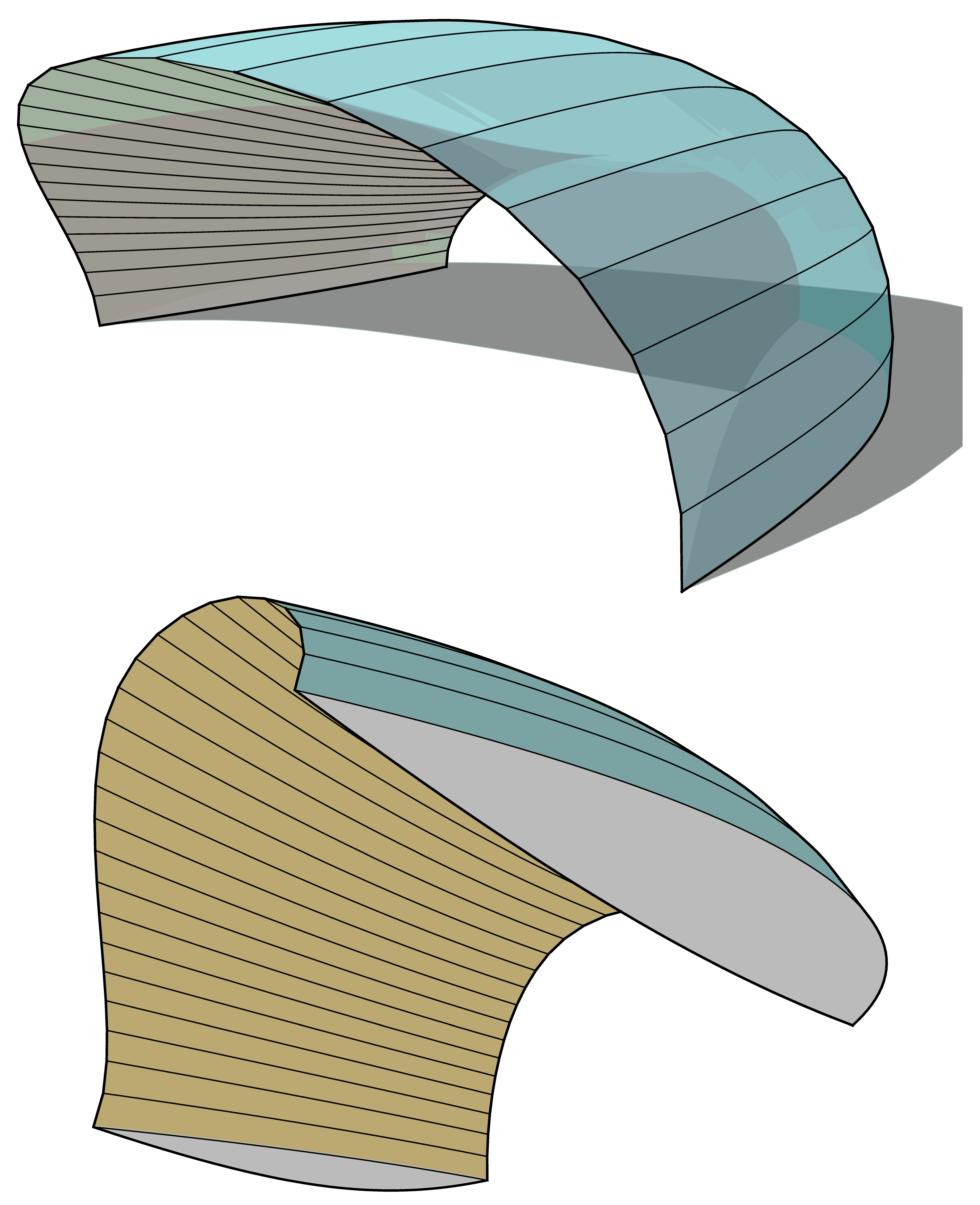
7. Method Four
Principle: ruling between primary cylindrical surface geometry created by method two produces secondary conical surfaces as described in method one.
Take a multi-surface shape generated by method two, use the ruled edges to draw secondary splines perpendicular to the splines created in the first instance (
Figure 18).
Figure 18.
A primary geometry as created in method two, see
Figure 13, with homothetic lines from the surface (red) used as construction for a secondary set of homothetic splines.
Figure 18.
A primary geometry as created in method two, see
Figure 13, with homothetic lines from the surface (red) used as construction for a secondary set of homothetic splines.
Note that each of these secondary splines
are homothetic scaled copies of each other, as with method one, so it is possible to rule between them and create conical developable surfaces, see
Figure 19 and
Figure 20, as described in method one. This is a ‘scale-trans’ surface as defined by Schlaich, Bergermann and Partners.
Note that with triangular initial polylines, the secondary splines will each be planar. However if baffles/bulkheads are required for stiffening, and if polylines with more than three nodes are used, then these initial polylines need to be planar in order for the secondary splines to be planar too.
Figure 19.
Developable surfaces generated by ruling between the secondary homothetic splines already created, see
Figure 18.
Figure 19.
Developable surfaces generated by ruling between the secondary homothetic splines already created, see
Figure 18.
Figure 20.
Developed surface created with method four. This is the 3D shape shown in
Figure 19.
Figure 20.
Developed surface created with method four. This is the 3D shape shown in
Figure 19.
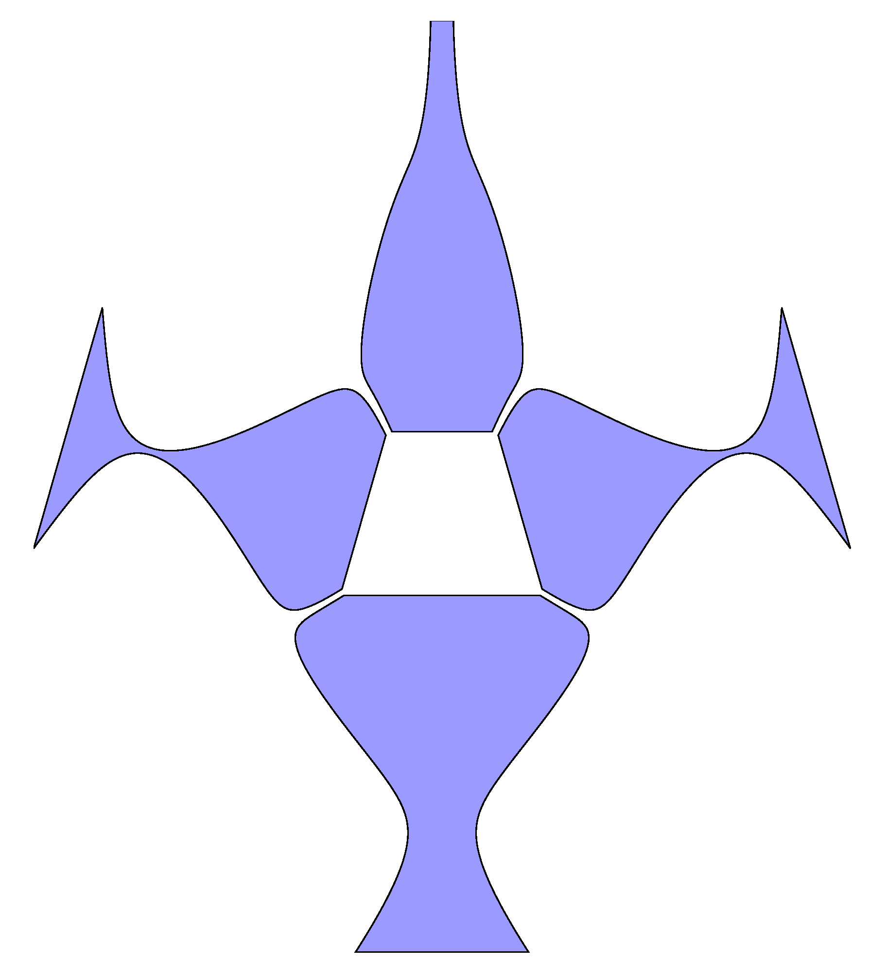
8. Method Five
In addition to scale and translation mapping, reflection mapping of splines can be used to create developable surfaces. These produce surfaces that are similar to method two,
i.e., quadrilaterals have parallel creases (
Figure 21). However it is not possible to simply generate secondary developable surfaces from the geometry created using this method, although for many ‘C’ and ‘O’ shaped sections there will be a developable solution as shown above in
Figure 3 and
Figure 4.
Figure 21.
Four reflection mapped splines, three mirror planes, and the generated developable surfaces.
Figure 21.
Four reflection mapped splines, three mirror planes, and the generated developable surfaces.
The developed surfaces created using this technique are symmetrical. Note also that the ends of each ‘panel’ are parallel, see
Figure 22.
Figure 22.
The developed developable surfaces created using method five.
Figure 22.
The developed developable surfaces created using method five.
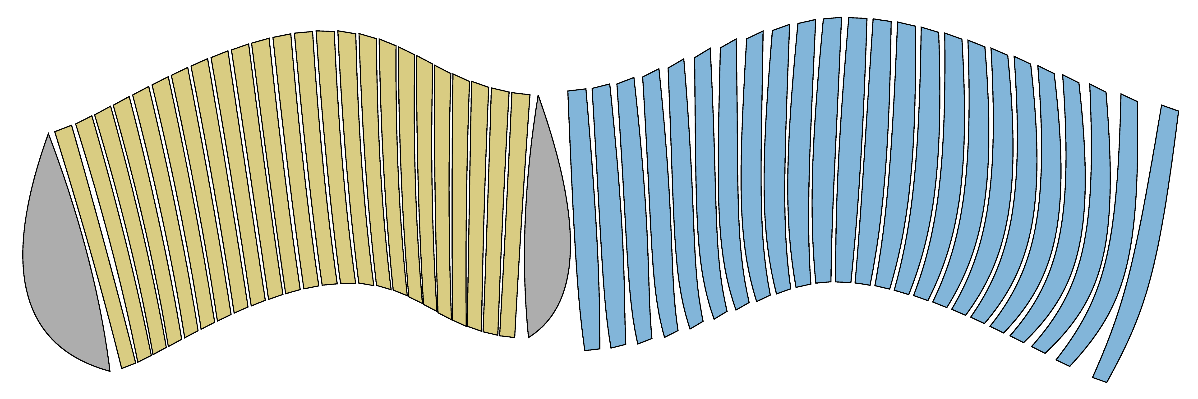
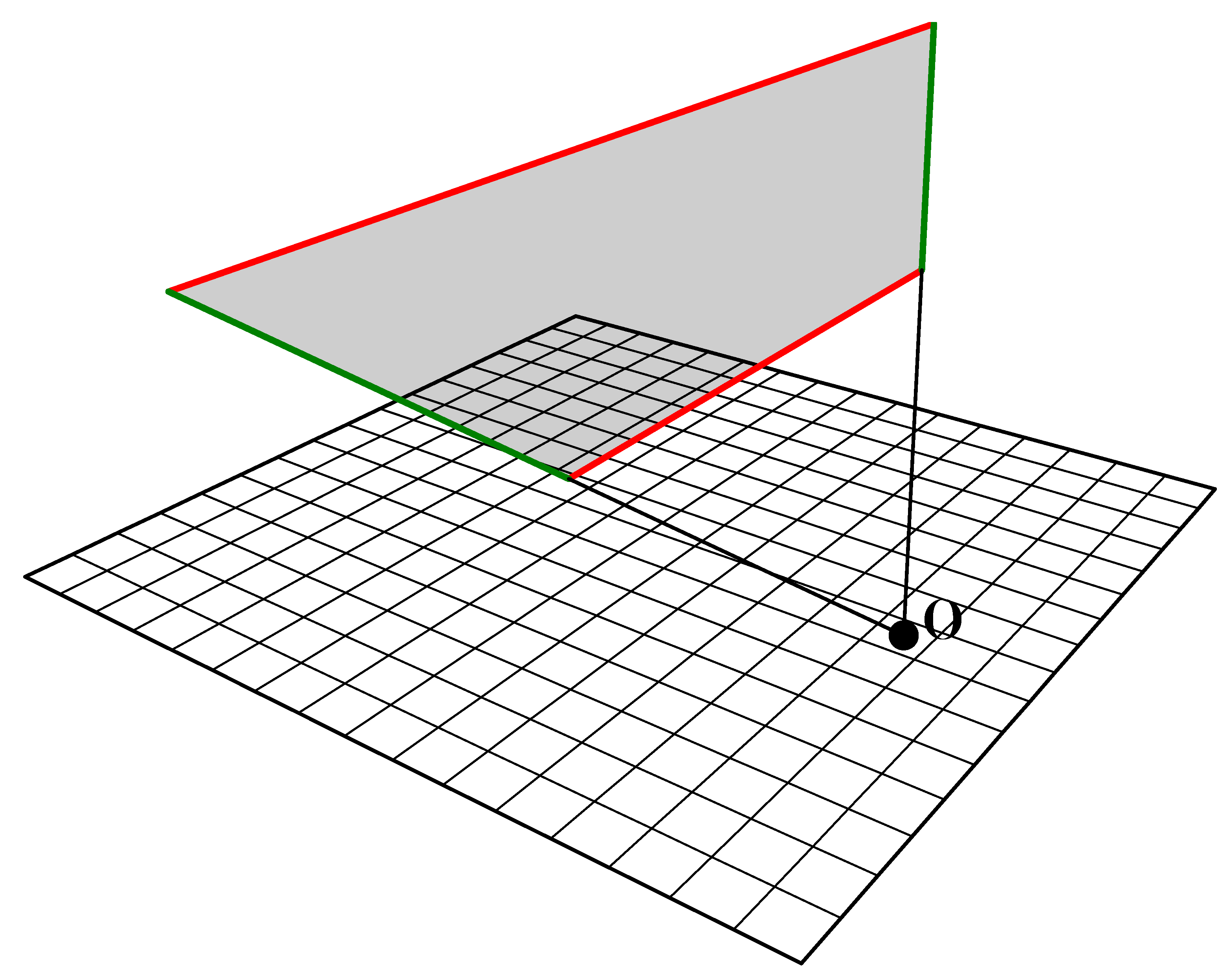
9. Homography
Any developable surface when transformed using a plane-preserving or collineated mapping will also be developable. It should be self-evident that a rotation or scale transformation of a developable surface will also be developable. It is also true that a shear or anisotropic scale transformation of an already developable surface will also be developable, though this is not so evident at first.
However these affine mappings are not that interesting since they can be trivially performed on the nodes of the original spline generation curves using standard CAD tools.
Of more interest is the observation that any
perspective homography transformation of an existing developable surface will also be developable. Most spline curves, e.g., Bezier, are invariant under perspective transformation, so it is not strictly necessary to perform the homography after the creation of the developable surface. However since some of the techniques above rely on the generation of equally spaced meshes, these require that the homography step be taken after the creation of surface meshes, see
Figure 23 for an example and
Figure 24 for the developed surfaces.
In detail, for the matrix of 3D coordinates in the surface model, the following homograpy needs to be performed:
The variable a can be any scalar value. Each x1, y1, z1 component then needs to be divided by w1:
The resulting mesh can then be further manipulated with anisotropic scale or shear transformations.
As a great number of homography transformations can be performed with wildly differing results, parameter fitting techniques can be used to obtain an optimised shape where the requirements are not purely artistic.
Note that planes that are parallel before transformation may not be parallel after the homography, and edges that were parallel before transformation will likely be radial after the homography.
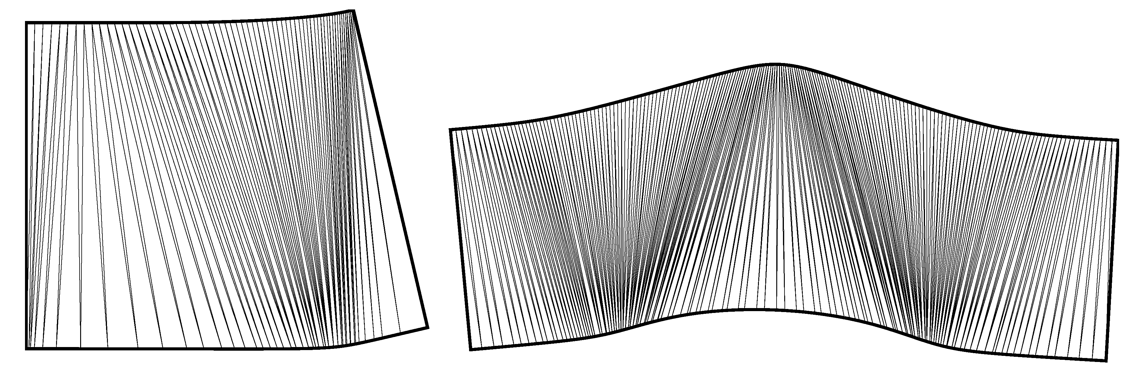
Figure 23.
Developed surfaces before and after a perspective homography transformation. The rear shape was created using method three. The transformed developable surface at the front is not possible to create directly through any of the five methods discussed previously.
Figure 23.
Developed surfaces before and after a perspective homography transformation. The rear shape was created using method three. The transformed developable surface at the front is not possible to create directly through any of the five methods discussed previously.
Figure 24.
Developed surfaces before and after a perspective homography transformation. The outline on the right is the untransformed shape developed, and the outline on the left is the developed version of the transformed shape.
Figure 24.
Developed surfaces before and after a perspective homography transformation. The outline on the right is the untransformed shape developed, and the outline on the left is the developed version of the transformed shape.
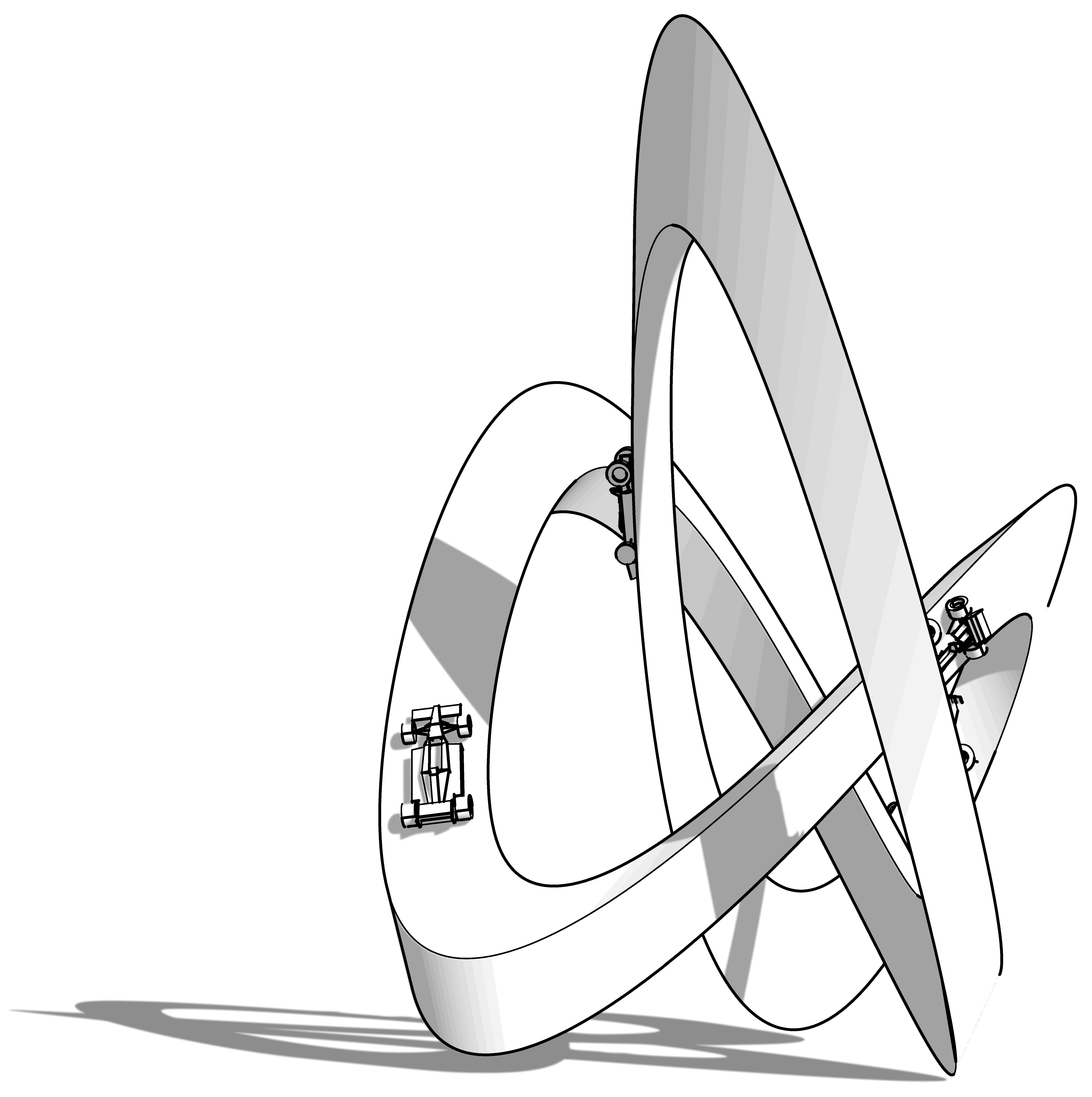
10. Built Work
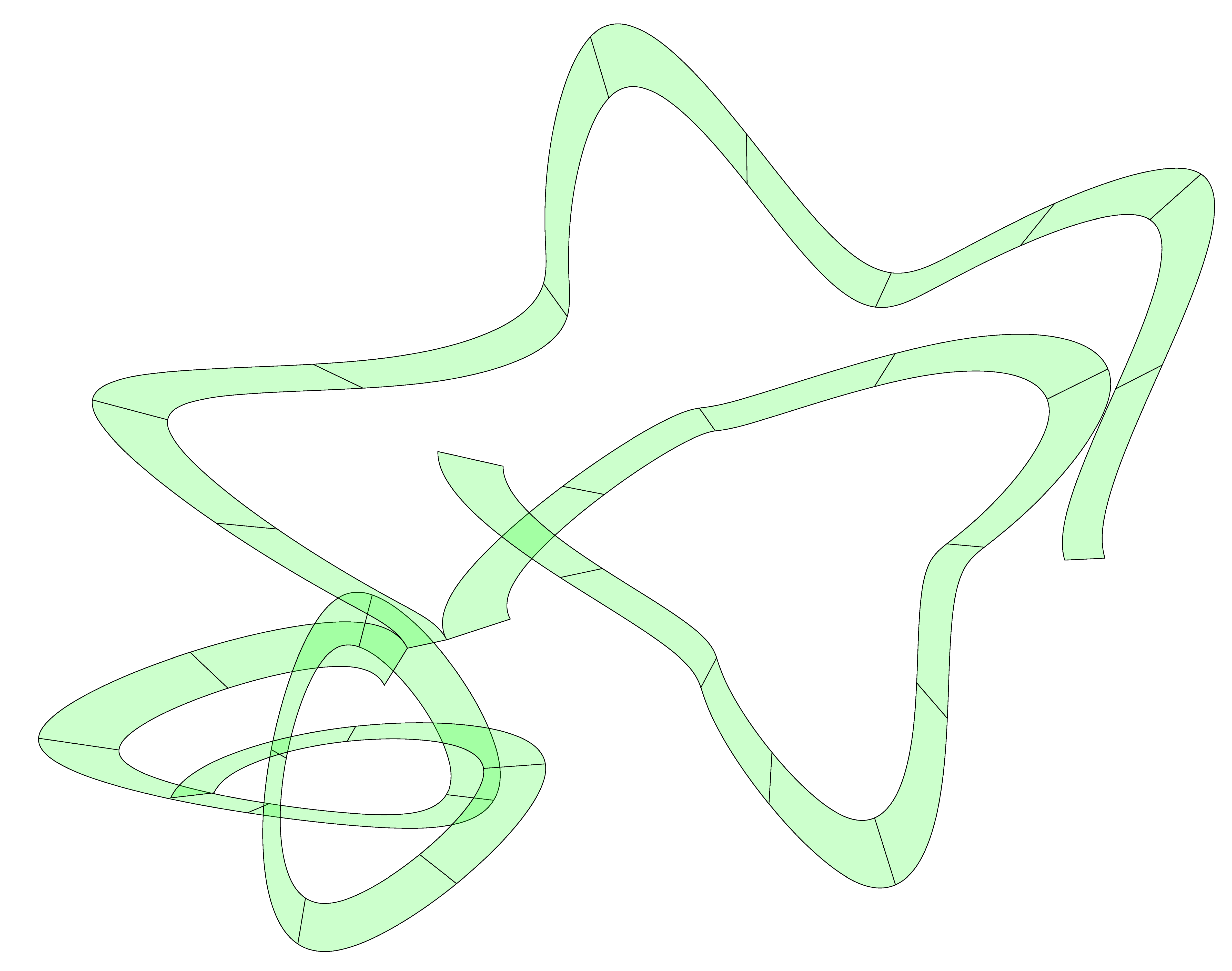
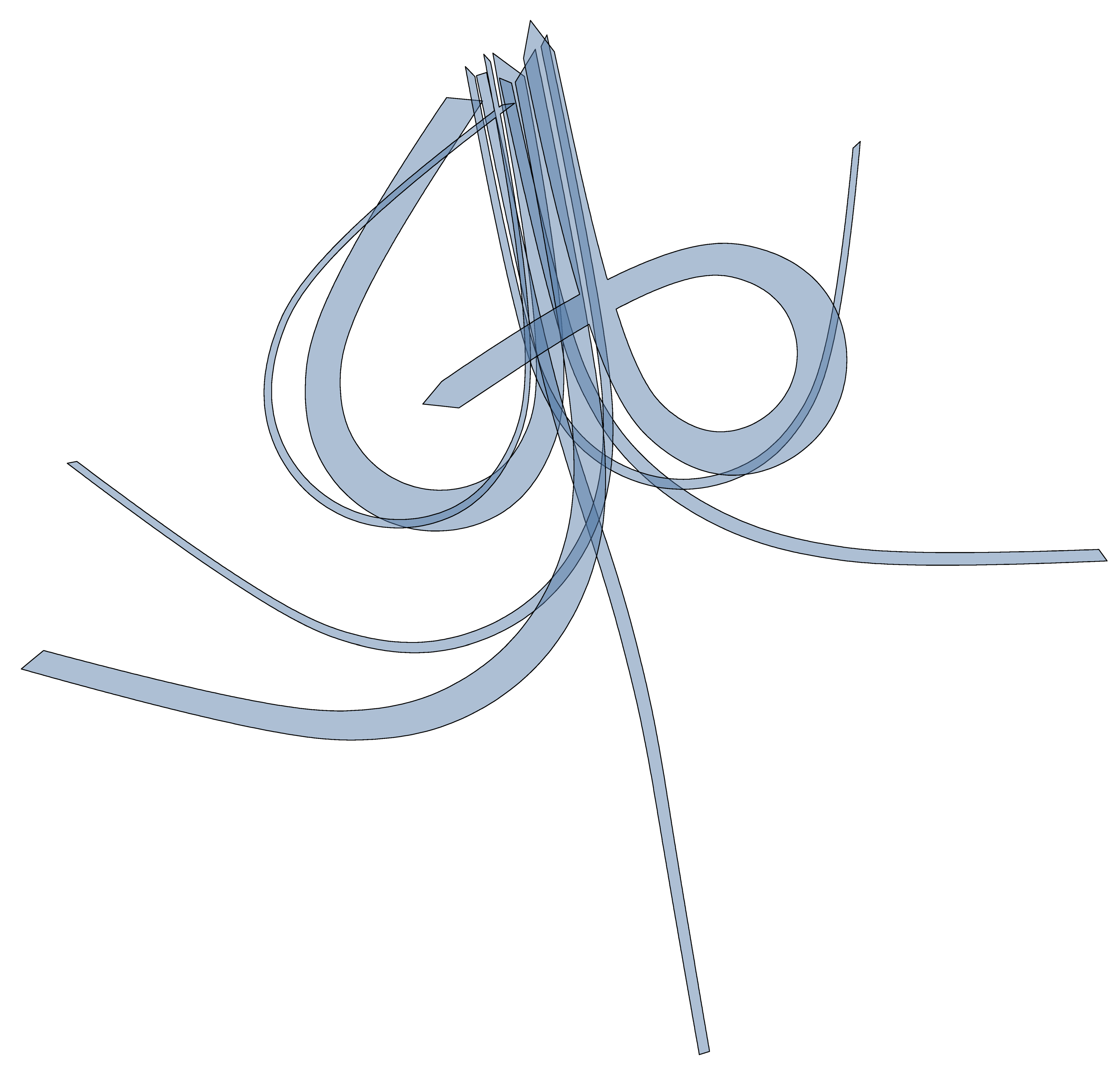
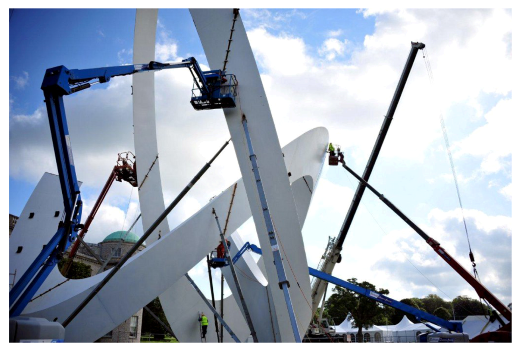
The Lotus sculpture for the 2012 Goodwood Festival of Speed, designed by the author in conjunction with the artist Gerry Judah, provides a good example of these techniques in action.
The structure has a method one geometry and the defining line is a closed spline in the form of a trefoil knot. Homothetic variants of this spline were used to generate a triangular prismatic manifold shell. The triangular cross-section combined with the continuous curvature of the three developable surfaces provided an extremely lightweight and rigid thin-shell structure.
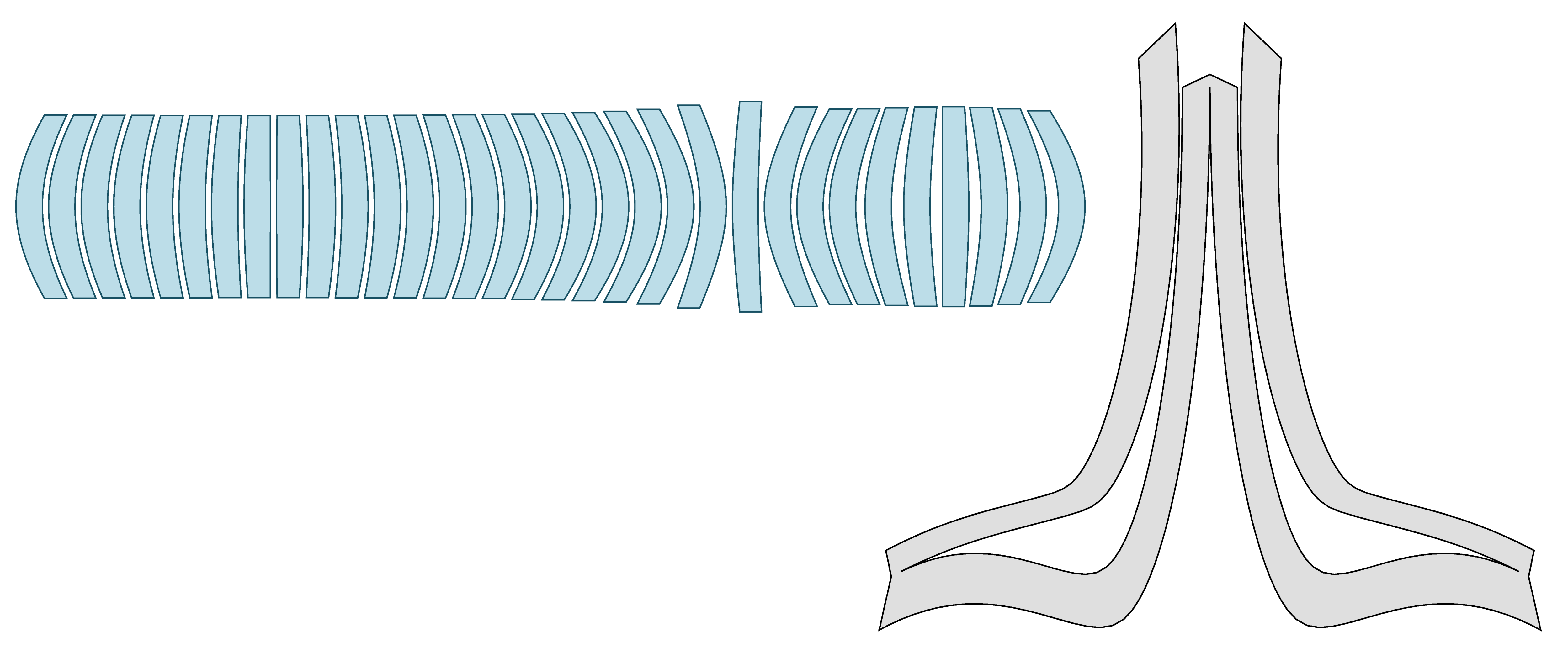
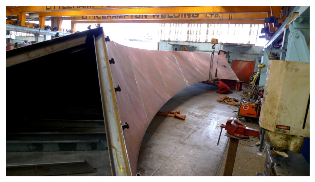
The overall height is 27 metres and the total weight, not-including foundations, is 60 tonnes. There is no internal framework or spine. The only structural components are the three surfaces themselves. These surfaces were developed in software into 2D cutting patterns (
Figure 26) and laser cut from 6 mm steel plate. The plates were then welded together into eleven transportable sections and site-welded into the finished piece.
Custom software was written by the author to convert the geometry into a finite element mesh that could be processed in the STAAD Pro structural analysis tool, where wind loading studies and structural dynamic analysis were used to verify the structure. Observed deflections and natural frequencies in the field under load were consistent with software predictions. A further paper will examine the design and performance of this structure in more detail.
Figure 25.
Sculpture in the form of a trefoil knot, 3D view.
Figure 25.
Sculpture in the form of a trefoil knot, 3D view.
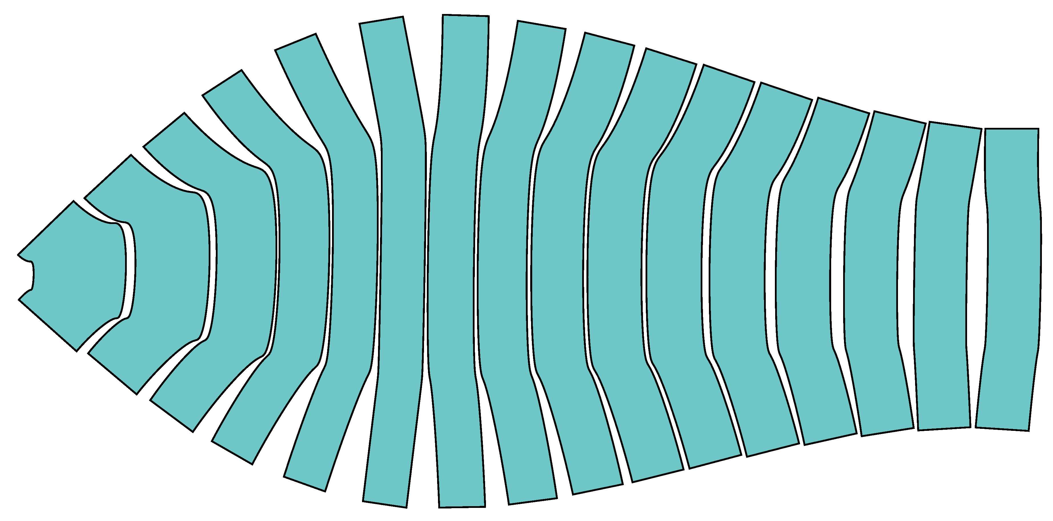
Figure 26.
Sculpture in the form of a trefoil knot, unrolled panels.
Figure 26.
Sculpture in the form of a trefoil knot, unrolled panels.
Figure 27.
Assembly of one segment. This is 18 m long and the full sculpture consists of eleven different segments.
Figure 27.
Assembly of one segment. This is 18 m long and the full sculpture consists of eleven different segments.
Figure 28.
Construction. The segments are installed incrementally. This photo shows the sculpture approximately 80% complete. The props provide temporary stability during construction and will be removed on completion. Photo by S. Horrod.
Figure 28.
Construction. The segments are installed incrementally. This photo shows the sculpture approximately 80% complete. The props provide temporary stability during construction and will be removed on completion. Photo by S. Horrod.
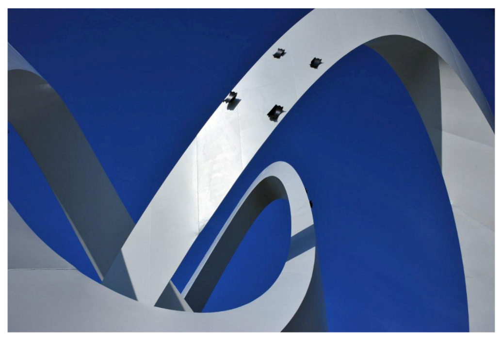
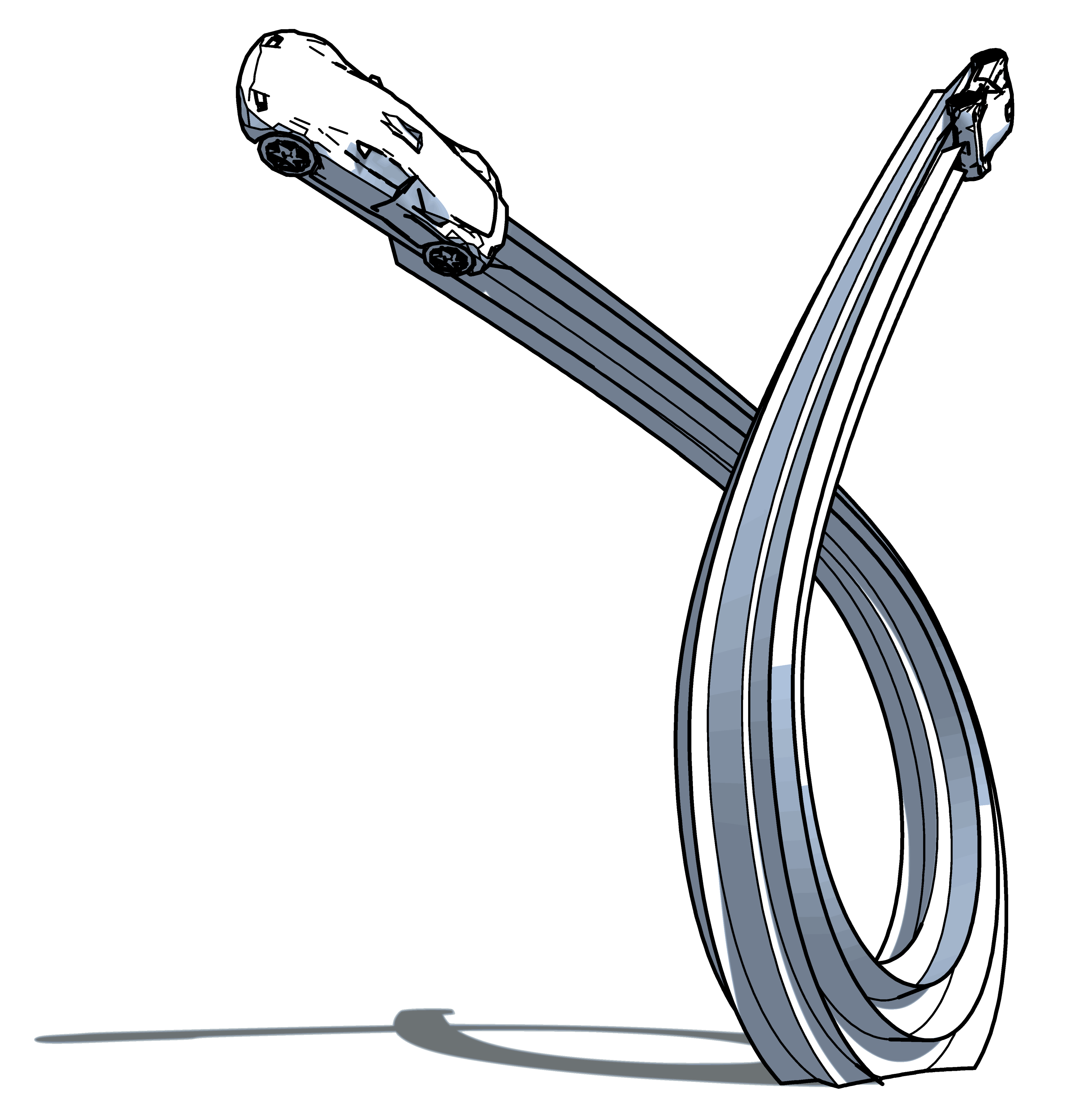
Figure 29.
Final shape. The black attachments are mounting points for the wheels of a display car. Photo by S. Horrod.
Figure 29.
Final shape. The black attachments are mounting points for the wheels of a display car. Photo by S. Horrod.
Figure 30.
Completed structure. This is a photograph. Cars are classic Lotus Formula 1 cars from 1964 to the present day.
Figure 30.
Completed structure. This is a photograph. Cars are classic Lotus Formula 1 cars from 1964 to the present day.
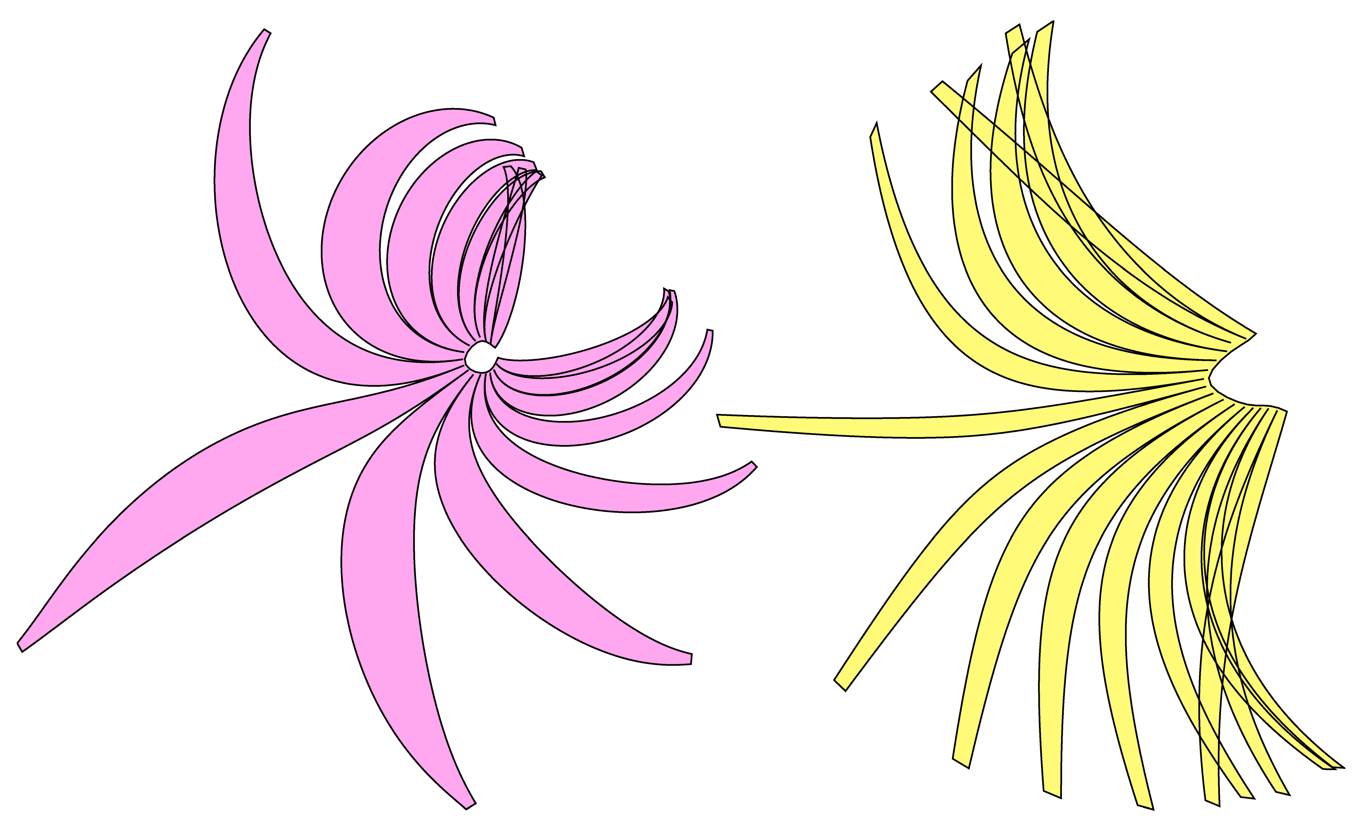
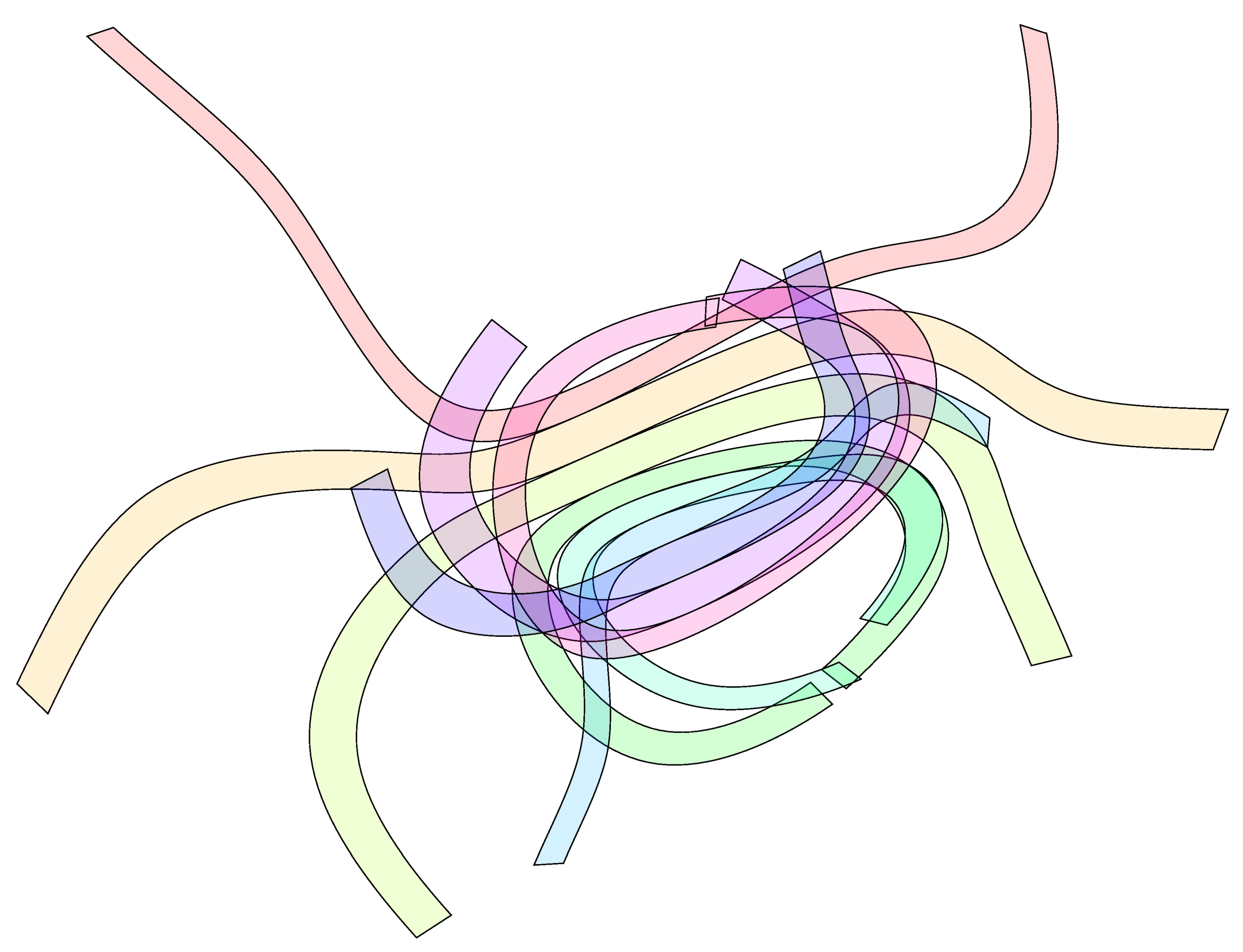
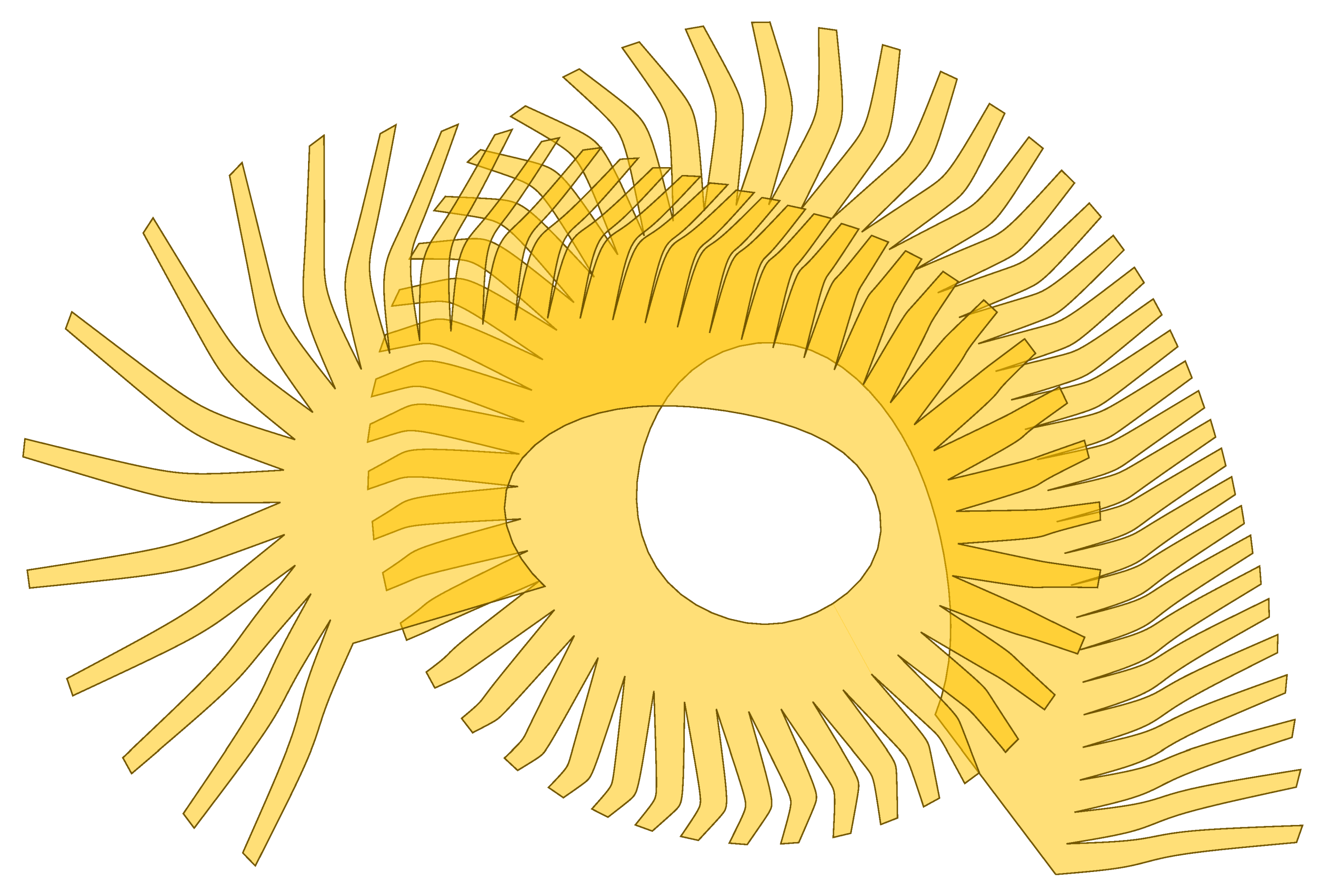
11. Speculative Works
Figure 31.
Homography sculpture, 3D view.
Figure 31.
Homography sculpture, 3D view.
Figure 32.
Homography sculpture, unrolled panels.
Figure 32.
Homography sculpture, unrolled panels.
Figure 33.
Mixture of method one and method three surfaces.
Figure 33.
Mixture of method one and method three surfaces.
Figure 35.
Two method three surfaces forming a hollow shell arch.
Figure 35.
Two method three surfaces forming a hollow shell arch.
Figure 37.
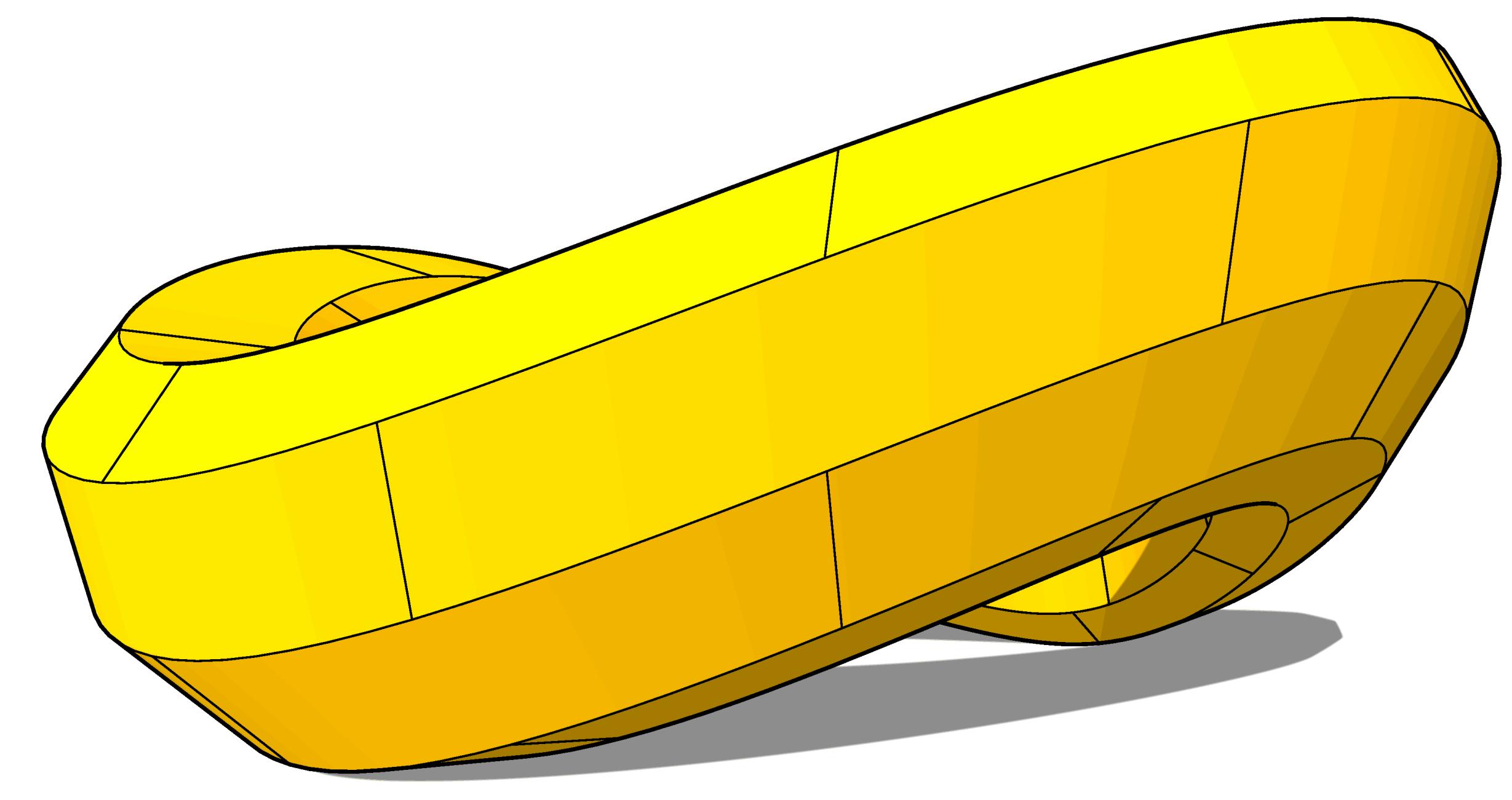
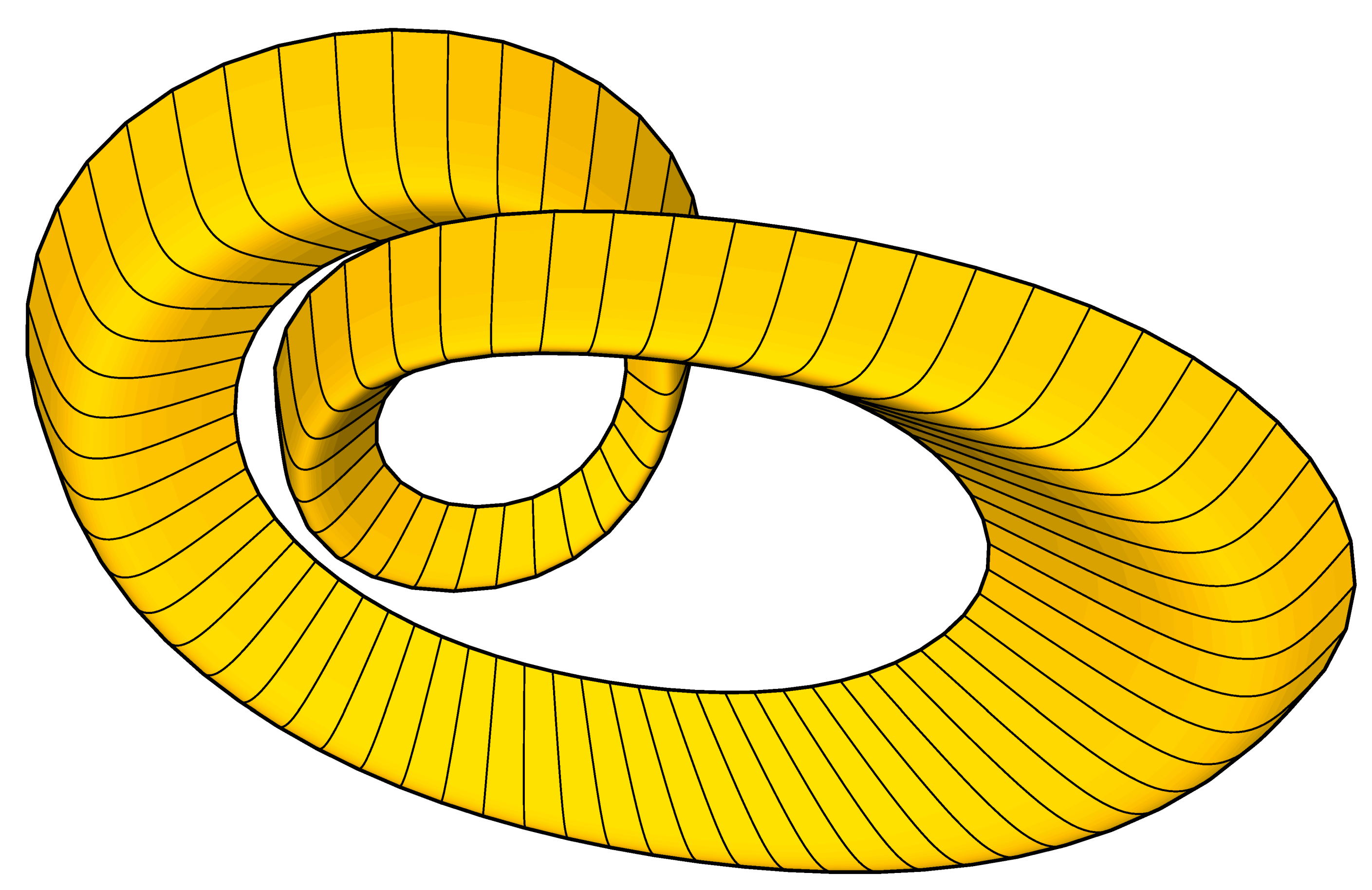
A method four surface in a free-form toroidal shape.
Figure 37.
A method four surface in a free-form toroidal shape.
Figure 39.
A method three surface in a free-form shape.
Figure 39.
A method three surface in a free-form shape.
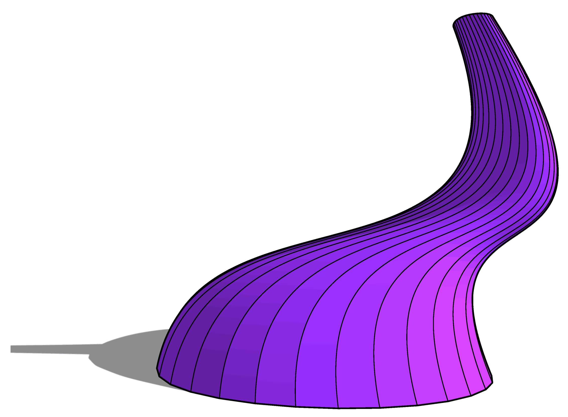
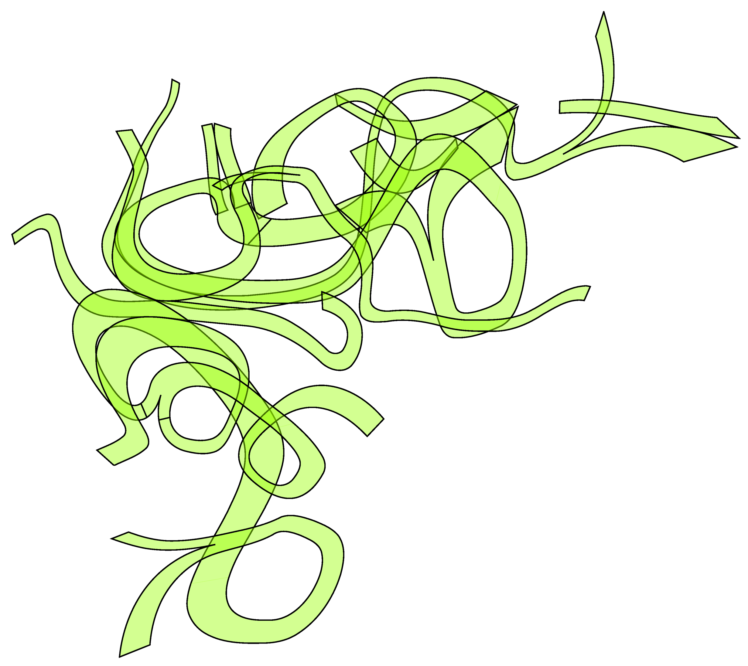
Figure 41.
A method four surface in a free-form shape.
Figure 41.
A method four surface in a free-form shape.
Figure 42.
An unrolled method four surface from
Figure 41.
Figure 42.
An unrolled method four surface from
Figure 41.
Figure 43.
Multiple method one surfaces in a free-form shape. This shape has an additional homography transformation.
Figure 43.
Multiple method one surfaces in a free-form shape. This shape has an additional homography transformation.
Figure 44.
Unrolled method one surfaces from
Figure 43.
Figure 44.
Unrolled method one surfaces from
Figure 43.
12. Materials and Practical Considerations
Although larger constructions need to be fully supported during assembly, some properties of these shells constructed from homothetic curves are useful during construction:
In all of the described surfaces, including surfaces transformed via homography, the crease lines are either parallel or radial, converging on a point. This means that any two crease lines picked from the surface are co-planar. Thus, since the opposite end edges of each surface are crease lines, any surface can be placed on flat ground with all four corners touching, which greatly simplifies jigging arrangements.
With any of the surfaces that include homothetic edges, i.e., method one and method four, these edges can be shown to be homothetic both in 3D and in the unrolled 2D form. One property of homothetic curves is that a line joining the ends of a curve will be parallel to the equivalent line joining the ends of the next curve. In this situation, the four corner points form a trapezium, both in the 3D form where they are co-planar as noted above and in the 2D unrolled form.
With any of the surfaces with a cylindrical roll, i.e., method two, method three and method five, all crease lines are parallel, and these lines stay parallel in the unrolled 2D form. Since opposite end edges of each surface are also crease edges, the ends of each surface are parallel and form a planar trapezium.
With any of the surfaces with a radial roll, i.e., method one, method four and any other surface transformed via homography, radial creases stay radial in the 2D unrolled form. Hence crease lines can be simply marked on any 2D section by intersecting the end edges and marking crease lines radial about this point. If stiffeners are required to support the material where the curvature is too low, these stiffeners can be added to the 2D panels using the same method.
Stiffeners are mentioned as it has been found to be useful to add linear stiffener elements periodically along the crease lines. These help to control bending of the material in the right direction during assembly, to support open ends, and to structurally stiffen areas with lower curvature.
Suitable materials for constructing rigid developable surfaces are sheet metals such as steel and aluminium, and other flexible materials such as plywood, cardboard, and polycarbonate. The first two can have relatively straightforward welded seams, whereas the other materials need additional fixing systems. One option is to assemble just the seam angle from welded metal and span between these seams using the non-weldable material.
These shapes are also suitable for construction using non-flexible materials such as glass. However in this case the technique described above using thin quadrilaterals to simulate continuous curves does not work. The solution is to rule the surfaces with larger faceted quadrilaterals and use these to construct larger planar glazing units.
13. Additional Uses
These techniques are potentially suitable for the creation of the following construction items.
Concrete shuttering. This can be either permanent steel shuttering providing reinforcement for the concrete inside, or temporary plywood for more traditional concrete systems with internal reinforcement.
Internal steel reinforcement for concrete shuttered as described above. This would be made in the same way, but with perforations and tags to key into the mass concrete and/or to support curved reinforcement bar.
Hollow cores for concrete shuttered and reinforced as described above.
Ductwork, curved spline shapes can be used to traverse awkward and confined spaces. Cold rolled-edge standing-seam techniques can be used to assemble long span self-supporting ductwork on-site.
Linear structural frameworks supporting walls, floors, roofs, glazing, or cladding.
Being able to reliably construct arbitrary 3D splines from plate materials should be useful for track supports in amusement park rides.
Self-supporting shell and bulkhead stiffened shell structures as shown in method three and method four will be lightweight, strong and relatively straightforward to construct.
Planar glazing and cladding systems. Any shape that can be constructed from rolled developable surfaces can also be constructed from quadrilateral planes of glass or rigid panels with steel framework following the edges, although in this case, strictly planar curves will be more useful for generation of planar steel frameworks.
14. Further Work
The technique for producing primary surfaces as described by method one and method two can be automated by constraining the node positions of the primary splines. It will be possible to extend existing 3D CAD tools such that groups of splines with these constraints can be manipulated together, ensuring that any ruled surfaces produced are developable.
The technique for generating secondary surfaces as described by method three and method four closely resembles a variety of NURBS surface with constraints on the relative node positions. It will be possible to extend existing surface modeling tools such that they only produce the developable shapes as described in this paper.
