Abstract
Extreme events often provoke critical structural vibrations, compromising building performance and resilience. Particle impact dampers (PIDs) are widely recognized as effective passive vibration control devices; however, their nonlinear dynamics and unpredictable particle motion limit adaptability under uncertain hazard conditions. This study introduces a pendulum-type PID configuration designed to enhance controllability and energy dissipation by tuning particle frequency through suspension. Both the primary structure and particles are modeled as pendulums, and their interactions are analyzed under free and forced vibration scenarios. A comprehensive parametric study reveals that increasing the frequency ratio (F.R), defined as the ratio of particle natural frequency to that of the structure, significantly improves damping efficiency. At F.R = 5.0, with clearance d = 0.1 and restitution coefficient e = 0.2, the system achieves an average damping ratio of approximately 0.28 in free vibrations. Under resonant forced vibration, the proposed damper reduces amplitude ratios to below 0.3 compared to undamped conditions. The results confirm that lower clearance and restitution values consistently yield superior damping performance. The findings demonstrate that the pendulum-type PID offers a customizable, cost-effective solution for mitigating structural vibrations, thereby contributing to risk-informed and resilience-oriented design strategies for building structures exposed to extreme events.
1. Introduction
Structural vibration control is incredibly important for most engineering structures such as bridges, high-rise structures, and even machinery. Researchers have been trying for decades to find solutions for structures under extreme events such as earthquakes [1] and wind-induced vibrations [2,3]. These applications require a vibration absorber which can work in low-frequency excitations. Among various passive vibration mitigation strategies, impact-based damping devices have attracted sustained interest due to their simplicity and robustness. One exciting passive vibration absorber for structural vibration control is considered to be particle impact dampers (PIDs). Particle impact dampers (PIDs) are the type of dampers where some particles are placed within cavities within the main structure or in an enclosure placed on the primary structure [4,5]. When the primary structure vibrates, the particles collide with the wall of the cavity or enclosure and mitigate the vibration. The damping comes from the impacts of particles with the primary structure and with other particles as well. The minimal maintenance, simple installation, and simple principle of damping give this class of dampers an advantage over other damping technologies. Besides the simple working principle, impact-based dampers show various nonlinear phenomena, which makes them difficult to study and analyze [6].
Researchers have presented various studies on the effectiveness of particle impact dampers [7,8,9,10,11]. Several efforts have focused on developing approximate analytical or numerical models to predict the response of the primary system and to identify the key parameters influencing damping performance. Researchers have tried to make some approximate models for PIDs to predict the response of the primary system and to find out the parameters affecting the damping performance. Then, the best combination of the parameters can be used in applications to improve the performance of PIDs. The initial study of vibration control based on impact dampers can be found in the early 1980s when C. N. Bapat [12] presented one of the initial studies on impact dampers. They presented a single-unit impact damper with one particle and concluded that the mass ratio, coefficient of restitution, and clearance are the parameters that influence the output. Zurawski et al. [13] then presented a new beam-like damper for the transient vibrations of light structures. After these initial studies, various similar studies [14,15,16,17] were conducted to see the performance of impact-based particle dampers with different methods for different applications by different designs. These initial studies validate that PIDs can be useful for future applications and require further studies to improve design and performance.
Due to the strong nonlinearity associated with impact dynamics, compact analytical investigations remained relatively limited, and several researchers subsequently focused on experimental approaches. M. Trigui and others [18] presented an experimental study on multi-particle impact dampers. They showed that particle dampers can be useful for beam vibrations as well and showed that significant damping can be achieved by PIDs. C. X. Wong and others presented a model to predict the energy dissipation of PIDs by the discrete element method (DEM). Zheng Lu and others [19] presented a study on particle impact dampers under dynamic loading. Gharib [20] presented a study on particle chain impact dampers. They presented a stacked PID with more than one section, and free vibration applications were studied. Other experimental studies [21,22,23,24] were performed based on different methods. Zheng Lu [25] presented a study where they studied various parameters affecting the performance of PIDs. Botan Shen and others [26] presented a compact experimental study for seismic control of high-rise structures by employing a double-layer tuned particle damper. Qi Wang and others [27] combined the concept of a tuned mass damper [28] with a spring–pendulum mechanism to generate impacts and enhance vibration dissipation. More recently, several studies have explored advanced impact-based and hybrid damping concepts, adaptive configurations, and resilience-oriented vibration mitigation strategies, indicating renewed interest in controllable and broadband passive damping solutions [29,30,31,32,33]. In addition to impact-based damping devices, viscoelastic dampers have also been widely investigated for vibration mitigation, offering distinct energy dissipation mechanisms and design trade-offs, as demonstrated in recent comparative experimental and numerical studies [34,35,36,37].
Earlier studies have improved the damping performance of impact dampers by employing various methods, designs, and theories. The significant parameters reported by earlier studies are mass ratio, coefficient of restitution, and clearance or gap. Notably, the intrinsic dynamic characteristics of the particle itself, particularly its effective vibration frequency, have received comparatively little attention. This can be an important parameter in the damping performance of the system. Numerous studies aim to improve damping, and, in such dampers, the damping is generated by the impact. If the particle has a higher frequency than the primary mass, there can be more impacts to generate more damping. The frequency of particles cannot be controlled in the presented designs as the particles are moving freely and even the motion cannot be predicted.
In this study, a novel pendulum-type particle impact damper is proposed to address the aforementioned limitations. To control the frequency of particle motion, the particles are hung (pendulum-type) within the primary structure while retaining the ability to impact the structure through strategically placed stoppers. By adjusting the suspension length, the natural frequency of the particle can be explicitly tuned, enabling controlled and predictable impact behavior. By modeling the particles as pendulums, the motion of the particle can be predicted as well. The vibration of high-rise structures is modeled as a pendulum representing the dominant vibration mode. Both the primary structure and the hanging particle are described using pendulum-based formulations to enable a unified analytical framework. Free and forced vibration responses are investigated through numerical simulations of the proposed model. The objective of this study is to provide a mechanism-level analytical investigation of a pendulum-type particle impact damper, with particular emphasis on isolating the governing dynamic interactions and parameter sensitivities introduced by particle frequency tuning. In the context of this study, structural resilience is interpreted in a performance-based sense, emphasizing reduced peak response and accelerated decay of vibrations following dynamic excitation, which are directly associated with improved post-event functionality and reduced damage potential. The results demonstrate that particle frequency plays a critical role in enhancing damping performance and that the proposed pendulum-type configuration is effective for both free and forced vibration scenarios.
2. Approximate Model
The approximate model of the system is presented in this section. The primary mass is shown by and the hanging mass by . The primary mass is modeled as a pendulum as mentioned earlier. The primary structure is represented as a pendulum-type single-degree-of-freedom system (SDOF), corresponding to the dominant vibration mode governing resonance response. This abstraction is commonly adopted in vibration control studies to capture the primary energy exchange mechanism while retaining analytical clarity. The particle is hung with a wire/rope with a length and the length of the primary mass is . There are two points on the primary structure (stoppers) where the particle can strike during the vibrations. The clearance between both points is denoted by (). When the primary mass or particle moves a distance , there will be an impact. The impact can be guaranteed in any sort of movement of any part (primary system or particle). The schematic diagram can be seen in Figure 1.
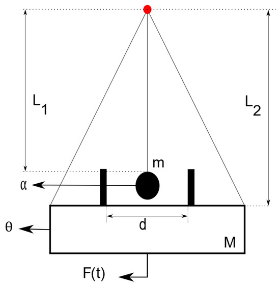
Figure 1.
Schematic diagram of PID.
The motion of the primary mass is represented by and the motion of the particle is represented as . The moving path of both objects is known as the equation of motion of both systems and can be derived. The primary system has a mass , and the particle mass is represented by . The equation of motion of the primary system for free vibrations () can be written as follows:
Dividing by and for small angles assuming , then there is the following:
For a primary system, the natural frequency can be written as . The equation becomes
With initial conditions as and , the response of the primary system can be determined as follows:
where and are the initial displacement and initial velocity of primary mass, respectively. The velocity () and acceleration of the primary mass at any time can also be calculated by taking the time derivative of displacement once and twice, respectively.
When the system is vibrating under external excitations, i.e., (), the equation of motion can be written as follows:
And the solution of this equation consists of both (homogeneous and particular solution). In the forced vibration response, the homogeneous solution dies down after some time, so the only particular solution is used to represent the vibrations. In this case, there are impacts to disturb the vibration of objects, and the initial conditions are changed after each object so there is a general solution; a combination of homogenous and particular solution is used to represent the response of the primary mass under external force.
The response of the system under external excitation can be described as follows:
Similarly, the velocity and acceleration of the primary system at any time is determined as follows:
The motion of the hanging particle is considered the motion of a simple pendulum. It has a length and the natural frequency . The motion of the hanging particle is free vibration as there is no driving force to it. The hanging particles oscillate only after the impact generated by the vibration of the primary mass.
The equation of motion of the particle can be written as follows:
The equation is solved using the same approximation () with initial conditions (initial displacement , and initial velocity ).
The velocity and acceleration of the particle can be determined as follows:
The principle of the proposed vibration absorption system is based on the impact of two objects with different masses. The motion of both objects is well defined in the previous section. Initially, the primary structure could vibrate under external excitation or free vibrations due to any sudden impact generated by wind or waves (for ships). The primary system will strike the hanging particle after traveling the distance . The constitution to detect the impact is set as follows:
where and are the displacements of the primary structure and hanging particles, respectively. The analytical formulation adopts several simplifying assumptions, including small-angle motion, point impacts, and negligible inherent structural damping. The small-angle approximation is consistent with vibration mitigation scenarios targeting resonance control, where response amplitudes remain moderate. Structural damping is intentionally neglected to isolate the energy dissipation mechanism introduced by particle impacts and to clearly assess its standalone effectiveness. Point impacts are assumed to retain analytical tractability and physical transparency; however, this idealization neglects finite contact duration and local compliance effects. As a result, the present model is best suited for conceptual design and parametric exploration, rather than detailed contact-level or material-specific analysis.
The hanging mass will always be at rest initially and it will move only by the impact generated by the primary structure. When an impact is detected, there will be momentum exchange and energy loss by the impact (depending on the nature of impact). The nature of impacts means the direction of both objects before impact and the magnitude of the coefficient of restitution between two bodies. The direction of both objects before impact is important as the impacts when both objects are moving in the opposite direction can damp the vibration of the primary structure. There will be some impacts when both objects are in the same direction, and theoretically there will be an addition of energy to the primary structure. This increase in the velocity of the primary structure is significantly small because the primary structure is quite heavy compared with the hanging mass (). The transfer of energy to the primary structure can be minimized by utilizing the coefficient of restitution . If the magnitude of C.O.R is small, the energy transferred to the primary mass can be minimum, but it will also decrease the conservation of momentum as well.
The equations for conservation of momentum and coefficient of restitution () are mentioned below.
where represents the velocities before impact and represents the velocities after impact while the coefficient of restitution is denoted as . The mass ratio is denoted by and determined as . Solving these equations for the velocities after impact gives
These equations are used to calculate the velocities of both objects after each impact, which are used as the initial conditions for the motion of objects after each object. The time of impact provides the position of impact as well. Therefore, the velocities after impact and position of objects at the time of impact become initial conditions for the equation of motion of the system after each impact.
All the equations mentioned above are modeled to simulate the response of the primary mass under different conditions. The free and forced vibration analysis is performed in this study. A perimetric study is also conducted to understand the effect of each parameter on vibration absorption.
3. Free Vibration Analysis
The free vibration analysis is conducted by taking . In a free vibration response, an initial condition (initial displacement, initial velocity) is required to initiate the vibrations of the system. In this study, the initial velocity is used to initiate the vibration of the primary structure. To understand the effect of each parameter on the damping and response of the primary mass, the simulations are performed by altering one parameter at a time and fixing all other parameters. The frequency of the particle is changed to study the effect on vibration absorption. A parameter frequency ratio is defined and , where is the natural frequency of the particle and is the natural frequency of the primary structure. The fixed parameters for the simulations are presented in Table 1. The mass ratio μ = 0.1 is selected to represent a commonly adopted upper-range value in particle-based damping studies, allowing clear observation of transient decay characteristics and damping trends in free vibration. The present study focuses on the role of particle frequency control; therefore, systematic mass ratio optimization is not pursued.

Table 1.
Parameters for the simulations.
3.1. Clearance ()
According to most of the studies on PID, the clearance () is the most influential parameter in the performance of PIDs. The clearance of the gap between the primary structure and particle determines the properties of both objects before impact. The properties can be tuned by choosing the optimum clearance value where more significant impacts are achieved. In previous studies, the particles are moving freely and require enough distance to obtain significant velocity before striking the primary structure to obtain better transfer of momentum and disturb the vibrations. In the proposed study, the particle is hung and has limited movement because of the pendulum-like motion. When the frequency of the particle is increased, the length of the wire is shortened, and the particle moves in a smaller circle. In this study, the optimum value of clearance becomes shorter to achieve more impacts, but choosing a value that is much shorter may lead to less vibration absorption due to the lack of velocity of both objects. The effect of clearance () on the response of the system subject to free vibration is studied at various frequency ratios and the results are presented below.
Figure 2 shows the displacement of primary mass in free vibrations. The natural frequency of the hanging mass is 1.5 times the natural frequency of primary mass. This shows that the hanging mass vibrates 1.5 times faster and generates impacts with the primary mass leading to energy dissipation. The vibrations of the primary structure are dampening through the impacts, and the effectiveness of the proposed damper is verified. Here it can be seen that the damping decreases as the clearance is increased. When the clearance is increased, the number of impacts decreases. The secondary mass has no impact after some time because of the large clearance. After initial impacts, the vibration amplitude has already decreased for both objects, and if the clearance is higher as well, it leads to no impacts after some time.
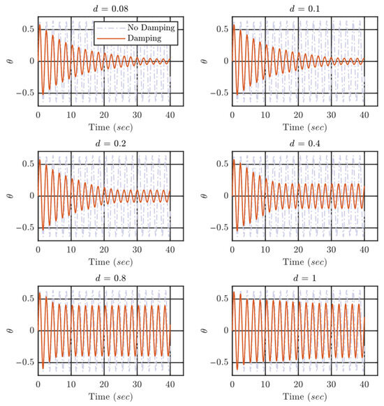
Figure 2.
Displacement of the primary structure () at different values of clearance () at , ,
Figure 3 shows the amplitude of the primary structure in free vibration response when the frequency ratio is tuned to 2. The natural frequency of the hanging mass is twice the natural frequency of the primary structure. The graphs clearly show that vibration absorption is improved by increasing the frequency ratio. The increased frequency ratio generates more impact with higher velocity leading to more energy dissipation. The frequency is increased by shortening the length as mentioned earlier. The short length of the wire limits the movement of the secondary mass and the damping at higher values of clearance decreases.
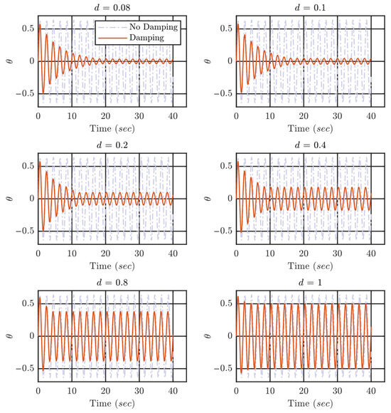
Figure 3.
Displacement of the primary structure () at different values of clearance () at , ,
Figure 4 shows the amplitude of the primary structure vibrations while the natural frequency of the hanging particle is four times the natural frequency of the primary structure. Here the improved vibration absorption can be seen for small values of clearance. The higher frequency of the hanging particle provides more impacts with higher velocities, and the energy dissipation is increased. The increase in the frequency ratio limits the clearance range as well. If the frequency ratio is much higher, significant damping can only be achieved at smaller values of clearance in free vibration response.
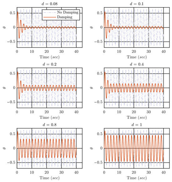
Figure 4.
Displacement of the primary structure () at different values of clearance () at , ,
Figure 5 shows the displacement of the primary structure when the frequency ratio is changed to five. Like previous cases, the damping performance improved significantly in free vibration analysis. The trend is found to be similar, for as the frequency ratio is increased, the vibration absorption also increases but for small clearance values.
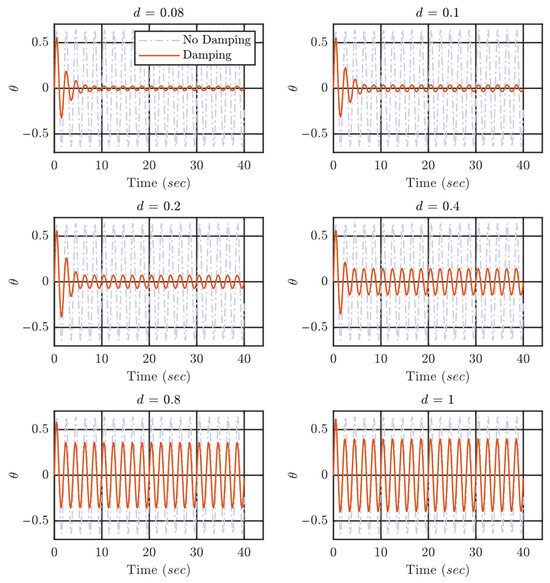
Figure 5.
Displacement of the primary structure () at different values of clearance () at , ,
Damping Ratio
The damping ratio is an important parameter to estimate the performance of any damper and can be calculated through various methods. One of the simple methods to calculate the damping ratio is the logarithmic decrement method [38]. This method requires maximum amplitude in consecutive cycles to calculate the damping ratio of the system. The damping ratio is evaluated based on the first five oscillation cycles, which correspond to the phase of dominant energy dissipation immediately following excitation. This choice ensures consistent comparison across configurations, as later cycles may exhibit reduced impact activity and increased sensitivity to amplitude fluctuations inherent to nonlinear impact dynamics. The reported damping ratios are therefore interpreted as relative performance indicators rather than absolute system properties.
Here and represents the maximum amplitude in two consecutive cycles (). For the smaller damping ratios, the damping ratio can be derived as follows:
The damping ratio is nonlinear throughout the process, and each case shows different damping at each cycle, so the average damping ratio of the first five cycles is used to compare the performance of each configuration.
The average damping ratio of the first five cycles in each configuration at different frequency ratios is calculated and shown in Figure 6 at different values of clearance and F.R. The damping ratio changes throughout the vibration of the primary structure. The damping ratio represents the energy absorption in each cycle. The energy of the system is decreasing due to the consistent impacts, and each impact changes the velocity of the primary mass. At larger values of the clearance, there are fewer impacts when the vibration amplitude of the system is equal to the value of clearance. Hence the damping is not significant and there are even no more impacts after some time, which leads to no damping at all. The average damping ratio of the first five cycles is used to distinguish the performance of the different configurations. The bar in the plot shows that the lowest value of clearance exhibits the maximum average damping ratio and that is due to more impacts even at lower amplitudes of vibrations.
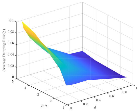
Figure 6.
The average damping ratio () at different frequency ratios and clearance. .
3.2. Coefficient of Restitution ()
The coefficient of restitution is used to determine the velocities after impact as stated in Equation (17). The energy loss and momentum exchange are inversely proportional to each other in terms of C.O.R. Smaller values are related to higher energy loss and lower momentum exchange and the higher values can be related to lower energy loss and higher momentum exchange. In this impact damping phenomenon, finding the best optimum values for better output could be a challenging task. If there are more impacts where both objects are in opposite directions, then choosing the higher values might increase the vibration absorption. In contrast to this, if there are more impacts where most impacts are in the same direction, then choosing higher values might lead to lesser dissipation, or even adding little energy to the primary structure and smaller values of C.O.R should lead to better energy dissipation.
Keeping the other parameters fixed, the proposed system is simulated for different values of C.O.R and the results are presented for different frequency ratios. Figure 7 shows the response of the primary structure at different values of C.O.R when the frequency ratio is 1.5. The graph shows that better vibration absorption is achieved at the smallest value while keeping the clearance constant.
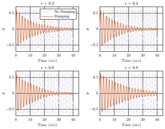
Figure 7.
Displacement of the primary structure () at different values of C.O.R () at , ,
Figure 8 shows the response of the primary structure when the frequency ratio is increased to two. Now the hanging particle is vibrating with twice the frequency of the primary structure. The higher value provides more momentum exchange between two bodies after each impact. At this frequency ratio, there are more impacts when both objects are in the same direction, and at higher C.O.R the momentum exchange is higher as well. The primary mass gains little energy due to higher momentum exchange when the particle strikes. Hence there is less energy dissipation when C.O.R has higher values if the frequency ratio is two. The response of the primary structure at frequency ratio 2 shows that the ending amplitude is quite similar in each case, but the process is different. Smaller values of C.O.R present more damping in the earlier phase of vibrations, and the response is more nonlinear as well. On the other hand, the damping in the first few cycles is not high in higher values of C.O.R but it continues to damp at later cycles, and the final amplitude is consistent with the small value of C.O.R. When the value of C.O.R is small, there is energy loss due to impact and the momentum exchange due to different masses as well, which leads to more damping in the first few cycles. In the later cycles, the amplitude dies down, and the velocity of the primary structure is quite low, and the energy dissipation becomes smaller as well. The process of vibration absorption can be understood by the displacement–velocity plot for different values of C.O.R.
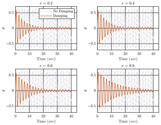
Figure 8.
Displacement of the primary structure () at different values of C.O.R () at , ,
Figure 9 shows the displacement-velocity plot at frequency ratio 2. The plot shows the change in velocity during the displacement of the primary structure due to impact. When C.O.R is small, the velocity of primary masses reduces significantly. There are various impacts when both objects are in phase, and there can be an increase in primary structure velocity depending on the configuration as mentioned before. The gain in primary structure velocity is significantly small in the case of smaller C.O.R and significantly higher when C.O.R is higher. This explains the lower dissipation of energy in the first few cycles when C.O.R is higher. The gain in velocity during the vibration does not let the system slow down quickly, and the system keeps vibrating for a longer period.
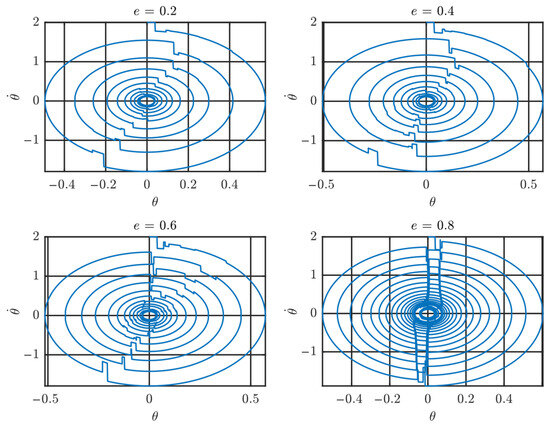
Figure 9.
The displacement–velocity plot at different values of C.O.R at .
Figure 10 shows the response of the primary structure when the frequency ratio is four. In this configuration, better energy absorption can be seen at the middle values of C.O.R. When the frequency ratio is increased, the transfer of momentum and energy dissipation due to C.O.R need to be optimum for the best output, and in this configuration, the best output is neither at the smaller C.O.R nor the higher C.O.R. The process to mitigate the vibration of the primary system is different in each case as explained in the previous configuration. The in-phase impacts transfer significant energy to the primary structure and vice versa, but the smaller values of C.O.R help mitigate some energy during the impact and the conservation of momentum is also smaller.
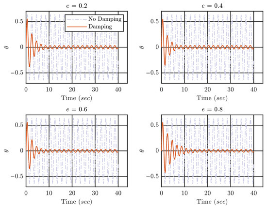
Figure 10.
Displacement of the primary structure () at different values of C.O.R () at , ,
Figure 11 shows the displacement–velocity plot of the primary structure at different values of C.O.R when the frequency ratio is four. A significant decrease or increase in the velocity of the primary structure can be seen, and this happens when both bodies impact while moving in opposite directions. These points are obvious in the plot. At , a higher number of impacts are observed, and energy is transferred to and from the primary system in each impact. The optimum vibration absorption happens at middle values of C.O.R although the output in each case is quite similar.
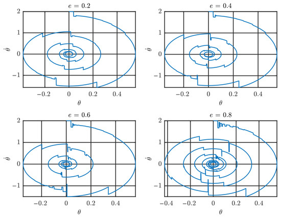
Figure 11.
The displacement–velocity plot at different values of C.O.R at .
It has a slight effect on the vibration absorption of the proposed absorber, but the application may allow a specific value of C.O.R. In vibration control application of some structures, a soft impact may be preferred due to the lesser harm to the primary structure during in-phase impact. When the objects are moving in the same direction, the impact can increase the velocity of the primary structure due to a hard impact in the case of a higher value of C.O.R.
Figure 12 shows the displacement of the primary structure when the frequency ratio is five. In this case, the natural frequency of the hanging particle is five times the natural frequency of the primary structure. Hence more impacts can be expected during the vibration of the primary structure. Higher natural frequency also means a shorter length of the wire to which a particle is attached. The graphs show that in any value of C.O.R, the vibration absorption due to impact is significant. The combination of conservation of momentum and C.O.R absorbs the vibration energy of the primary system quite significantly. The system reaches lower amplitude in very few cycles. Like the previous configurations, the optimum performance of the absorber is found at the middle values of C.O.R. A similar trend is found in the process to absorb vibration energy.
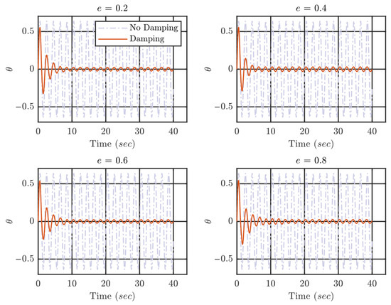
Figure 12.
Displacement of the primary structure () at different values of C.O.R () at , ,
Conservation of momentum between two masses during the vibration and the energy dissipation due to the coefficient of restitution absorbs the energy through impacts. The combination shows a similar trend in different configurations. The displacement–velocity plot at frequency ratio 5 is shown in Figure 13. The plot shows a similar trend to the previous configuration. The system exchanges momentum between two masses differently at different values of C.O.R. The higher values of C.O.R have more conservation of momentum during the impacts while the lower values of C.O.R dissipate vibration energy due to no inelastic impacts. The smaller values of C.O.R provide smooth dissipation of energy through soft impacts while the higher values will transfer energy to the primary mass due to higher velocities and hard impact, but in some cases this could be beneficial in overall output. Hence an optimum combination might work well with middle values of C.O.R to accommodate significant conservation of momentum and slight inelastic collisions to dissipate the vibration energy. Repeated particle impacts may generate localized contact forces that, if not properly managed, could lead to wear or fatigue of the surrounding structure. In the present study, optimal performance is obtained for relatively low coefficients of restitution, which inherently limit peak impact severity by promoting inelastic energy dissipation. In practical implementations, impact-related effects may be mitigated through appropriate material selection, compliant interfaces, or replaceable contact surfaces. A detailed assessment of impact forces and local stresses is identified as an important topic for future experimental and numerical studies.
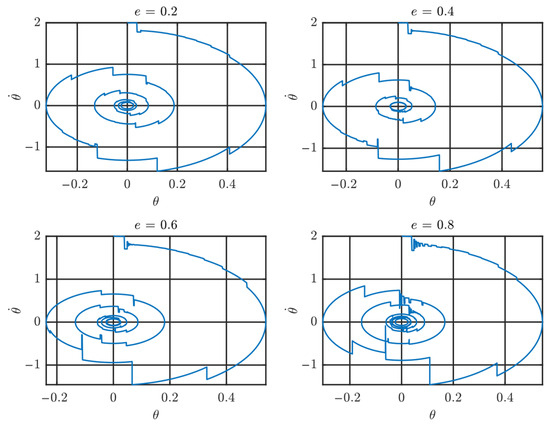
Figure 13.
The displacement–velocity plot at different values of C.O.R at .
The coefficient of restitution is not a material property because it can be changed with the shape of the material and the nature of collisions. The coefficient of restitution can still be predicted from the material properties and the velocities of the impact when the parameters of the collision are simplified. To predict this, it is assumed that the colliding objects have their center of mass and relative velocities in line. Theoretical estimation of the coefficient of restitution can be made when a ball is dropped onto a surface [39].
And . In Equation (18) the parameters are described as follows:
- = dynamic yield strength;
- = effective elastic modulus;
- = density;
- = velocity of impact;
- = Poisson’s ratio.
Damping Ratio ()
The damping ratio is calculated from the amplitude of the vibrations through the logarithmic decrement method as mentioned in the previous section. The damping ratio is calculated for different values of C.O.R at each frequency ratio mentioned in the previous section.
Figure 14 shows the average damping ratio at different frequency ratios and C.O.R. The graph shows that the damping ratio increases significantly by increasing the frequency ratio irrespective of C.O.R. The effect of C.O.R is little compared with the effect of the frequency ratio. The difference between the damping ratio at each value of C.O.R is small. Hence the system provides significant damping irrespective of the value of the coefficient of restitution. Depending on the requirement of the application, the coefficient restitution can be altered. The frequency ratio plays a huge part in improving the vibration absorption of the primary structure through impacts in free vibration analysis.
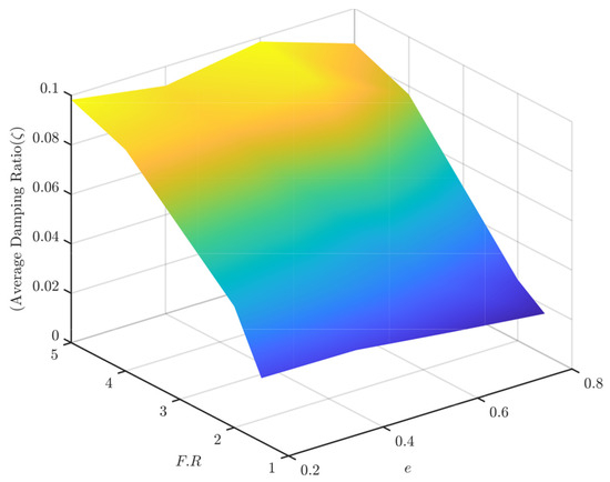
Figure 14.
The average damping ratio () at different frequency ratios and C.O.R.
4. Forced Vibrations
In this section, there is an external excitation force applied to the primary structure. The theory of the system is explained in earlier sections. The response of the primary system under external excitation is determined by Equation (8). A similar approach is used to determine the response of the primary structure under external force. Impacts are identified during the vibration of the primary system, and the velocities after impact are calculated and fed as the initial conditions. The parameters for simulation are presented in Table 2. The mass ratio is lowered for forced vibrations because here the impact is guaranteed as the system will keep obtaining enough amplitude due to external excitation. A smaller mass of particles could be enough to disturb the motion and avoid exponential increment in the amplitude at resonance. For forced vibration analysis, a lower mass ratio μ = 0.02 is adopted to reflect practical design constraints typically associated with continuously excited systems. While mass ratio is known to influence damping efficiency, the objective here is to isolate the effect of controllable particle frequency under realistic mass limitations.
Table 2.
Parameters for forced vibration simulations.
The excitation frequency of the external force is equal to the natural frequency of the primary structure to generate the response at resonance. The excitation frequency is selected to coincide with the natural frequency of the primary structure in order to examine damper performance under resonance conditions, representing a critical worst-case scenario. While real-world excitations are typically broadband, the present analysis focuses on resonance response to isolate and highlight the damping mechanism introduced by particle frequency control. Extension to off-resonance and broadband excitations is identified as an important topic for future investigation. The amplitude increases exponentially if the structure is excited with a frequency equal to the natural frequency of that structure. There are various methods employed to avoid resonance at first, but in some cases it is unavoidable. Various measures are taken to lower the amplitude of the vibration at resonance. The other damping technologies require significant changes to the structure, huge additional mass, or those that are very costly. In forced vibration analysis, the impacts will be generated in each cycle because the primary structure is excited by the external force and the amplitude will never be too low as in the case of free vibrations. Considering the resonance, the amplitude will always increase.
4.1. Clearance ()
Clearance has been very influential in vibration absorption for free vibration response. In forced vibration response, the clearance might have similar significance. If clearance is large, there will be an impact after the system travels a large distance, but vibration absorption is guaranteed. Choosing any value of clearance will generate significant vibration absorption because system amplitude is always increasing and there will be impacts in any case. The influence of clearance could be controlling the vibration amplitude at a specific level. If the clearance is large, the maximum amplitude of the system could be larger but always less than the amplitude without impact. If the clearance is too small, there will be more impacts, but they might not be significant due to lesser change in relative velocities.
Figure 15 shows the amplitude of vibrations at resonance at different values of clearance when the frequency of hanging particles is 1.5 times the frequency of the primary structure. The graphs show that any value of clearance prevents resonance but depending on the value of clearance, the maximum amplitude is different. The lower values of clearance have a better response of vibration because the amplitude is controlled within a small magnitude. If there is no damping, the amplitude of vibration keeps increasing exponentially, but using a secondary mass can control the amplitude very well.
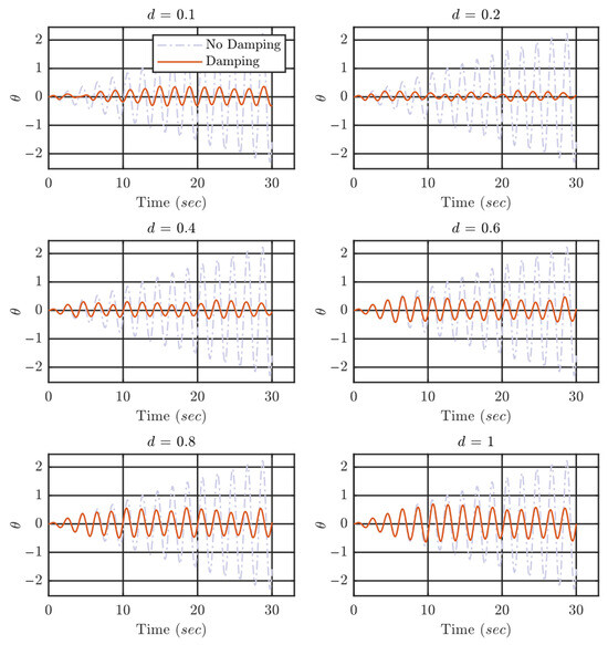
Figure 15.
Displacement of the primary structure () at different values of clearance () at resonance , , .
Figure 16 shows the amplitude of vibration when the frequency of hanging particles is two times the natural frequency of the primary structure. The graph shows that there is not a lot of difference compared with the previous case. The vibration dissipation can be seen at any value of clearance and the amplitude at a higher value of clearance is slightly larger. Compared with the previous configuration, the amplitude at larger values of clearance is better. Hence, the frequency ratio of hanging particles to the primary structure influences the vibration dissipation at larger values of clearance.
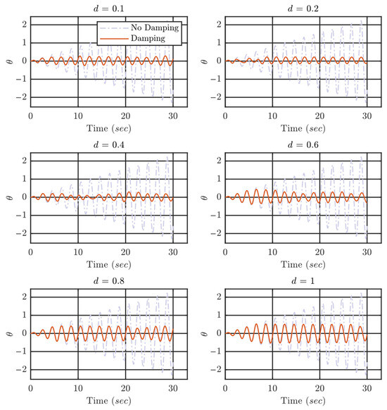
Figure 16.
Displacement of the primary structure () at different values of clearance () at resonance , , .
Figure 17 shows the amplitude of vibrations while the natural frequency of the hanging particle is four times the natural frequency of the primary structure. The higher frequency ratio should provide more impacts with a higher velocity of hanging particles, but the response is quite like the previous cases. The performance can be distinguished in terms of maximum amplitude at different configurations, but the overall response looks quite similar in the force vibration case. The disturbance caused to the forced vibration by the impact provides enough energy dissipation during the cycles to avoid resonance.
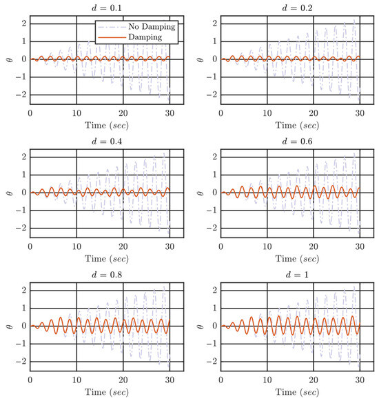
Figure 17.
Displacement of the primary structure () at different values of clearance () at resonance , , .
Figure 18 shows the amplitude of vibrations when the frequency ratio is tuned to five. This means the hanging particle has five times the natural frequency of the primary structure.
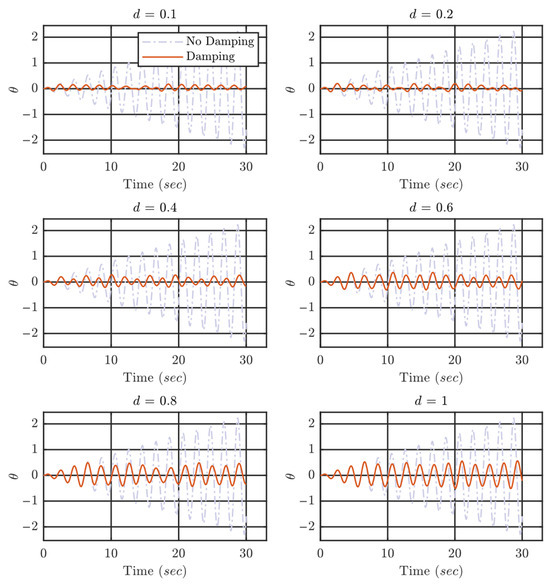
Figure 18.
Displacement of the primary structure () at different values of clearance () at resonance , , .
A slight improvement can be seen compared to the previous configurations. The maximum amplitude in each case has dropped a little bit compared to the previous cases. The overall influence of parameter is shown in these figures. The clearance helps to control the maximum amplitude of vibration. Smaller clearance can control the amplitude at a small magnitude while the larger clearance provides lightly larger amplitudes of vibration. The overall effect of the frequency ratio () and clearance can be evaluated by calculating the amplitude ratio for each value of clearance and the frequency ratio. The amplitude ratio is the ratio of maximum amplitude in a specific case to the maximum amplitude of vibration without damping. The amplitude ratio provides a measure to distinguish the configurations and select a better configuration for better output.
Figure 19 shows the three-dimensional surface to clarify the effect of clearance () and frequency ratio () on the amplitude ratio. The amplitude ratio shows how much amplitude is reduced compared with no second mass response. The lower amplitude ratio shows that the specific configuration dissipated more energy and the amplitude stayed lower. The maximum amplitude of damped vibration is used in this measurement, so this represents the whole configuration output. The surface shows that the amplitude stayed low at the smallest value of clearance irrespective of the frequency ratio. Increasing the clearance decreases the amplitude reduction, and maximum amplitude at higher values of clearance is larger as well.
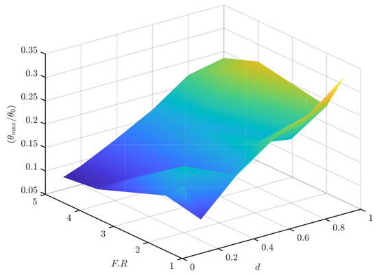
Figure 19.
Three-dimensional surface representing the effect of clearance and frequency ratio on amplitude ratio. ,
4.2. Coefficient of Restitution ()
The coefficient of restitution () determines the nature of impacts as explained earlier. The larger values of C.O.R improve conservation of momentum while the smaller values of C.O.R provide higher energy dissipation due to impact. The optimum combination of momentum exchange and energy dissipation provides better vibration absorption to the primary structure. In the free vibration system analysis, any value of C.O.R at a larger frequency ratio (F.R) provided significant damping. C.O.R determines the velocities of objects after impact, so using a higher magnitude of C.O.R might transfer momentum to the primary structure in some of the cases. In forced vibration, the velocity of the primary structure will not die due to the influence of external force, so the smaller values of C.O.R might be useful as they will improve the energy dissipation in each impact.
Figure 20 shows the amplitude of vibration of the primary structure at resonance when the natural frequency of the hanging particle is 1.5 times the natural frequency of the primary structure. The graph shows that the response at a larger value of C.O.R is slightly higher than the other configurations. This is due to the larger momentum exchange at a larger value of C.O.R. In forced vibration systems, the focus should be on the energy dissipation which is provided by the smaller value of C.O.R.
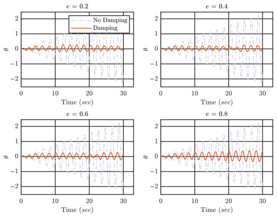
Figure 20.
Displacement of the primary structure () at different values of C.O.R () at resonance , ,
Figure 21 shows the response of the primary structure at resonance when the natural frequency of the hanging particle is two times the natural frequency of the primary structure. The graph shows that each value of C.O.R provides significant vibration absorption to the primary structure. In this configuration, the amplitude of vibration is well controlled by the impacts.
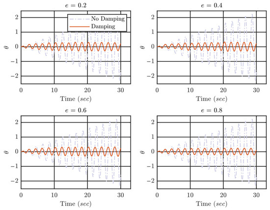
Figure 21.
Displacement of the primary structure () at different values of C.O.R () at resonance , ,
Figure 22 shows the displacement of the primary structure when the frequency ratio is tuned to four. The higher frequency of the hanging particle generates more impacts, and the amplitude of the vibrations is controlled. The resonance is avoided in any value of C.O.R. This shows that choosing any value of C.O.R or frequency ratio works well in terms of vibration control of structure at resonance.
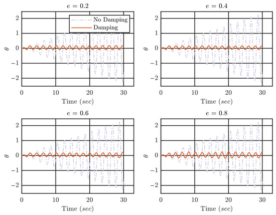
Figure 22.
Displacement of the primary structure () at different values of C.O.R () at resonance , ,
The vibrations of the primary structure are controlled in any case, but the process is quite different in all cases. Impacts at larger values of C.O.R end in momentum exchange as explained earlier but also may transfer harmful stress due to hard impacts on the primary structure. The smaller values of C.O.R provide better output in most cases. Hence, using a smaller value of C.O.R might be helpful for the health of the structure and might be necessary for some applications. In applications where the stress induced to the primary structure does not matter much, larger values of C.O.R can be employed.
To distinguish the different configurations of the C.O.R and frequency ratio, the amplitude ratio is calculated similarly to the previous section. The amplitude ratio is the ratio of maximum amplitude on each value of C.O.R to the maximum amplitude without a damper. The amplitude ratio determines the performance of the specific configuration.
Figure 23 shows the three-dimensional surface to demonstrate the effect of C.O.R and frequency ratio on the amplitude ratio. The smaller amplitude ratio means that the specific values mitigated the vibration of the primary system very well. The surface shows that the minimum value of amplitude ratio is found when , . The smaller magnitude of C.O.R dissipates more energy with the help of more impacts generated by the larger frequency ratio.
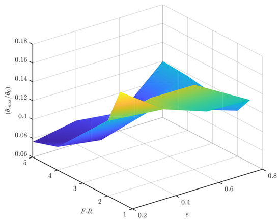
Figure 23.
Three-dimensional surface representing the effect of C.O.R and frequency ratio on amplitude ratio. ,
5. Conclusions
In this study, a nonlinear pendulum-type particle impact damper is proposed for structural vibration control applications. The motion of particles is controlled by hanging it by a wire, and the particle can vibrate as well with a natural frequency rather than the free motion. The natural frequency of the particle is employed to generate more impacts with the primary structure. The larger natural frequency of the hanging particle compared with the natural frequency of the primary structure generates more impacts and better vibration absorption. A model is generated by considering the vibration of a high-rise structure as a pendulum also. The free and forced vibration analysis is performed. In forced vibration analysis, the resonance frequency is used to excite the primary structure. Furthermore, a compact parametric analysis for better vibration absorption is performed to study the effect of clearance, C.O.R, and frequency ratio on vibration dissipation.
- The proposed frequency ratio, which is the ratio of the natural frequency of the hanging particle to the natural frequency of the primary structure, has a huge influence on the vibration dissipation by impacts in free vibration response. The higher frequency ratio generates more impact with higher velocities and dissipates more vibration energy compared to the smaller frequency ratio.
- In the parametric study of free vibrations, the clearance () and C.O.R () influence the damping ratio significantly. The results show that the smaller value of clearance and C.O.R provides the best damping ratio. Due to the nonlinear damping, the average damping ratio of the first few cycles is employed in this study to distinguish between different configurations. The maximum average damping ratio is achieved at , , in free vibration analysis.
- In force vibration analysis, the amplitude ratio is calculated to distinguish between different configurations. The amplitude ratio is the maximum amplitude at a specific configuration of parameters to the maximum amplitude without damping. The amplitude ratio is influenced by clearance and C.O.R.
- Like the free vibration response, the best damping performance is found in the smaller values of clearance and C.O.R. The influence of C.O.R and clearance is slightly less compared with the free vibration analysis. The proposed mechanism works well in vibration control in free and forced vibrations. The vibration control of the proposed mechanism is better than that of the work presented in the literature, especially at the resonance excitations.
Author Contributions
Conceptualization, M.A.A. and H.R.; methodology, M.A.A., H.R., and N.H.; software, M.A.A. and H.R.; validation, M.A.A., H.R., and N.H.; formal analysis, M.A.A., H.R., and N.H.; investigation, M.A.A., H.R., and N.H.; resources, M.A.A.; data curation, M.A.A. and H.R.; writing—original draft preparation, M.A.A. and H.R.; writing—review and editing, M.A.A., H.R., and N.H.; visualization, H.R.; supervision, H.R.; project administration, N.H.; funding acquisition, H.R. All authors have read and agreed to the published version of the manuscript.
Funding
This research received no external funding.
Data Availability Statement
The original contributions presented in this study are included in the article. Further inquiries can be directed to the corresponding author.
Acknowledgments
We acknowledge support given by Department of Mechanical Engineering, The Hong Kong Polytechnic University.
Conflicts of Interest
The authors declare no conflicts of interest.
References
- Geng, F.; Ding, Y.; Song, J.; Li, W.; Li, A. Passive control system for seismic protection of a multi-tower cable-stayed bridge. Earthq. Struct. 2014, 6, 495–514. [Google Scholar] [CrossRef]
- Nagarajaiah, S.; Jung, H.-J. Smart tuned mass dampers: Recent developments. Smart Struct. Syst. 2014, 13, 173–176. [Google Scholar] [CrossRef]
- Aly, A.M. Vibration control of high-rise buildings for wind: A robust passive and active tuned mass damper. Smart Struct. Syst. 2014, 13, 473–500. [Google Scholar] [CrossRef]
- Akbar, M.A.; Wong, W.O.; Rustighi, E. Design optimization of a single-mass impact damper. J. Sound Vib. 2024, 570, 118019. [Google Scholar] [CrossRef]
- Lu, Z.; Zhang, H.; Sami, F.M. Studies on vibration control effects of a semi-active impact damper for seismically excited nonlinear building. Smart Struct. Syst. 2019, 24, 95–110. [Google Scholar]
- Wong, C.; Rongong, J. Control of Particle Damper Nonlinearity. AIAA J. 2009, 47, 953–960. [Google Scholar] [CrossRef]
- Meyer, N.; Seifried, R. Damping prediction of particle dampers for structures under forced vibration using effective fields. Granul. Matter 2021, 23, 64. [Google Scholar] [CrossRef]
- Jin, J.; Kim, H.; Koh, H.-I.; Park, J. Railway noise reduction by periodic tuned particle impact damper with bounce and pitch-coupled vibration modes. Compos. Struct. 2022, 284, 115230. [Google Scholar] [CrossRef]
- Prasad, B.B.; Duvigneau, F.; Juhre, D.; Woschke, E. Damping performance of particle dampers with different granular materials and their mixtures. Appl. Acoust. 2022, 200, 109059. [Google Scholar] [CrossRef]
- Zhang, Y.; Cheng, J.; Xu, W.; Wang, C.; Liu, J.; Li, Y.; Yang, S. Particle Damping Vibration Absorber and Its Application in Underwater Ship. J. Vib. Eng. Technol. 2022, 11, 2231–2248. [Google Scholar] [CrossRef]
- Lu, Z.; Zhou, C.; Rong, K.; Zhang, J.; Du, J. Vibration Reduction Mechanism of a Novel Enhanced Particle Inerter Device. Int. J. Struct. Stab. Dyn. 2023, 23, 2350009. [Google Scholar] [CrossRef]
- Bapat, C.N.; Sankar, S. Single Unit Impact Damper in Free and Forced Vibration. J. Sound Vib. 1985, 99, 85–94. [Google Scholar] [CrossRef]
- Zurawski, M.; Zalewski, R. Damping of Beam Vibrations Using Tuned Particles Impact Damper. Appl. Sci. 2020, 10, 6334. [Google Scholar] [CrossRef]
- Chua, G.S.; Pacheco, B.M.; Fujino, Y.; Ito, M. Classical Impact Damper and Pendulum Impact Damper for Potential Civil Engineering Application. Doboku Gakkai Ronbunshu 1990, 416, 113–124. [Google Scholar] [CrossRef][Green Version]
- Ema, S.; Marui, E. Damping Characteristics of an Impact Damper and its Application. Int. J. Mach. Tools Manuf. 1996, 36, 293–306. [Google Scholar] [CrossRef]
- Cheng, C.C.; Wang, J.Y. Free vibration analysis of a resilient impact damper. Int. J. Mech. Sci. 2003, 45, 589–604. [Google Scholar] [CrossRef]
- Mao, K.; Wang, M.Y.; Xu, Z.; Chen, T. Simulation and Characterization of Particle Damping in Transient Vibrations. J. Vib. Acoust. 2004, 126, 202–211. [Google Scholar] [CrossRef]
- Trigui, M.; Foltete, E.; Abbes, M.S.; Fakhfakh, T.; Bouhaddi, N.; Haddar, M. An experimental study of a multi-particle impact damper. Proc. Inst. Mech. Eng. Part C J. Mech. Eng. Sci. 2009, 223, 2029–2038. [Google Scholar] [CrossRef]
- Lu, Z.; Wang, D.; Masri, S.F.; Lu, X. An experimental study of vibration control of wind-excited high-rise buildings using particle tuned mass dampers. Smart Struct. Syst. 2016, 18, 93–115. [Google Scholar] [CrossRef]
- Gharib, M.; Karkoub, M. Experimental Investigation of Linear Particle Chain Impact Dampers in Free-Vibration Suppression. J. Struct. Eng. 2017, 143, 04016160. [Google Scholar] [CrossRef]
- Els, D.N.J. Damping of Rotating Beams with Particle Dampers: Experimental Analysis. AIAA J. 2011, 49, 2228–2238. [Google Scholar] [CrossRef]
- Mirzabagheri, S.; Sanati, M.; Aghakouchak, A.; Khadem, S. Experimental and numerical investigation of rotational friction dampers with multi units in steel frames subjected to lateral excitation. Arch. Civil Mech. Eng. 2015, 15, 479–491. [Google Scholar] [CrossRef]
- Wang, D.; Wu, C. Vibration Response Prediction of Plate with Particle Dampers Using Cosimulation Method. Shock. Vib. 2015, 2015, 270398. [Google Scholar] [CrossRef]
- Zalewski, R.; Chodkiewicz, P. Semi-active linear vacuum packed particles damper. J. Theor. Appl. Mech. 2016, 54, 311–316. [Google Scholar] [CrossRef]
- Lu, Z.; Chen, X.; Zhou, Y. An equivalent method for optimization of particle tuned mass damper based on experimental parametric study. J. Sound Vib. 2018, 419, 571–584. [Google Scholar] [CrossRef]
- Shen, B.; Xu, W.; Wang, J.; Chen, Y.; Yan, W.; Huang, J.; Tang, Z. Seismic control of super high-rise structures with double-layer tuned particle damper. Earthq. Eng. Struct. Dyn. 2020, 50, 791–810. [Google Scholar] [CrossRef]
- Wang, Q.; Li, H.-N.; Zhang, P. Vibration Control of a High-Rise Slender Structure with a Spring Pendulum Pounding Tuned Mass Damper. Actuators 2021, 10, 44. [Google Scholar] [CrossRef]
- Weber, F.; Borchsenius, F.; Distl, J.; Braun, C. Performance of Numerically Optimized Tuned Mass Damper with Inerter (TMDI). Appl. Sci. 2022, 12, 6204. [Google Scholar] [CrossRef]
- Akbar, M.A.; Wong, W.-O.; Rustighi, E. A Hybrid Damper with Tunable Particle Impact Damping and Coulomb Friction. Machines 2023, 11, 545. [Google Scholar] [CrossRef]
- Dharmajan, N.B.; AlHamaydeh, M. State-of-the-Art Review of Structural Vibration Control: Overview and Research Gaps. Appl. Sci. 2025, 15, 7966. [Google Scholar] [CrossRef]
- Wang, B.; Xue, J.; Wei, J.; Liu, K.; Zhou, R. Experiment and numerical simulation on the performance of multiple unidirectional single-particle dampers under seismic excitation. Earthq. Eng. Struct. Dyn. 2024, 53, 1982–2005. [Google Scholar] [CrossRef]
- Sun, X.; Ilanko, S.; Mochida, Y.; Tighe, R.C. A Review on Vibration-Based Damage Detection Methods for Civil Structures. Vibration 2023, 6, 843–875. [Google Scholar] [CrossRef]
- Papalou, A. Evaluation of Multi-Compartment Particle Dampers for the Attenuation of Dynamic Vibrations. Vibration 2023, 6, 556–565. [Google Scholar] [CrossRef]
- Xu, Y.; Mao, M.; Huang, X.-H.; Guo, Y.-Q.; Yang, Y.; Dong, Y.-R.; Shah, S.A.A.; Gao, X.; Usman, M.; Jeong, S.-H. Comparative investigation of dynamic damping and fracture in viscoelastic dampers with two different interfacial bonding types: Molecular dynamics simulations and device tests. J. Build. Eng. 2025, 116, 114582. [Google Scholar] [CrossRef]
- Awada, A.; Younes, R.; Ilinca, A. Review of Vibration Control Methods for Wind Turbines. Energies 2021, 14, 3058. [Google Scholar] [CrossRef]
- Zhang, H.; Li, A.; Su, Y.; Xu, G.; Sha, B. Viscoelastic dampers for civil engineering structures: A systematic review of constructions, materials, and applications. J. Build. Eng. 2024, 96, 110597. [Google Scholar] [CrossRef]
- Shu, Z.; You, R.; Xie, Y. Viscoelastic Dampers for Vibration Control of Building Structures: A State-of-Art Review. J. Earthq. Eng. 2024, 28, 3558–3585. [Google Scholar] [CrossRef]
- Palm, W.J. Mechanical Vibration; John Wiley: Hoboken, NJ, USA, 2007. [Google Scholar]
- Jackson, R.L.; Green, I.; Marghitu, D.B. Predicting the coefficient of restitution of impacting elastic-perfectly plastic spheres. Nonlinear Dyn. 2010, 60, 217–229. [Google Scholar] [CrossRef]


Disclaimer/Publisher’s Note: The statements, opinions and data contained in all publications are solely those of the individual author(s) and contributor(s) and not of MDPI and/or the editor(s). MDPI and/or the editor(s) disclaim responsibility for any injury to people or property resulting from any ideas, methods, instructions or products referred to in the content. |
© 2025 by the authors. Licensee MDPI, Basel, Switzerland. This article is an open access article distributed under the terms and conditions of the Creative Commons Attribution (CC BY) license.