
Group Effect on In-Plane Shear Performance in Wooden Nail Connections


Abstract
1. Introduction
2. Materials and Methods
2.1. Materials
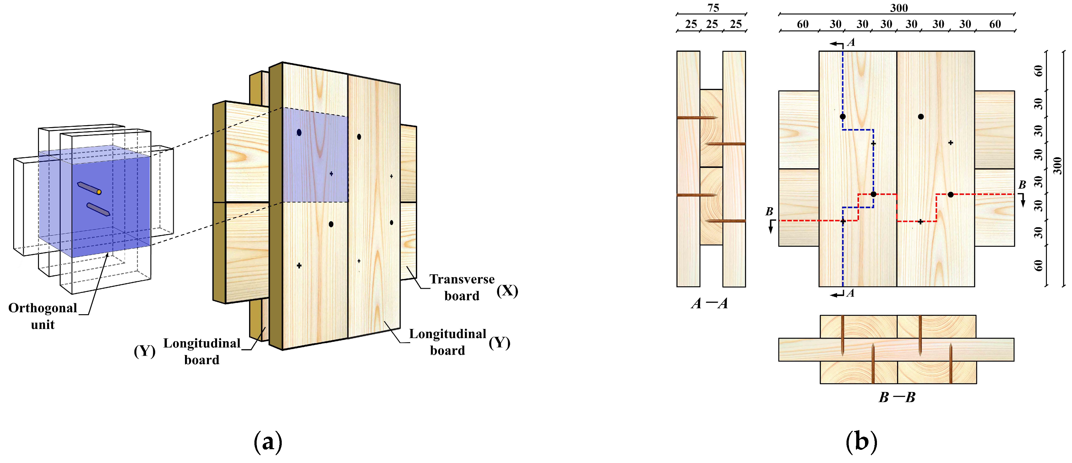
2.2. Specimens
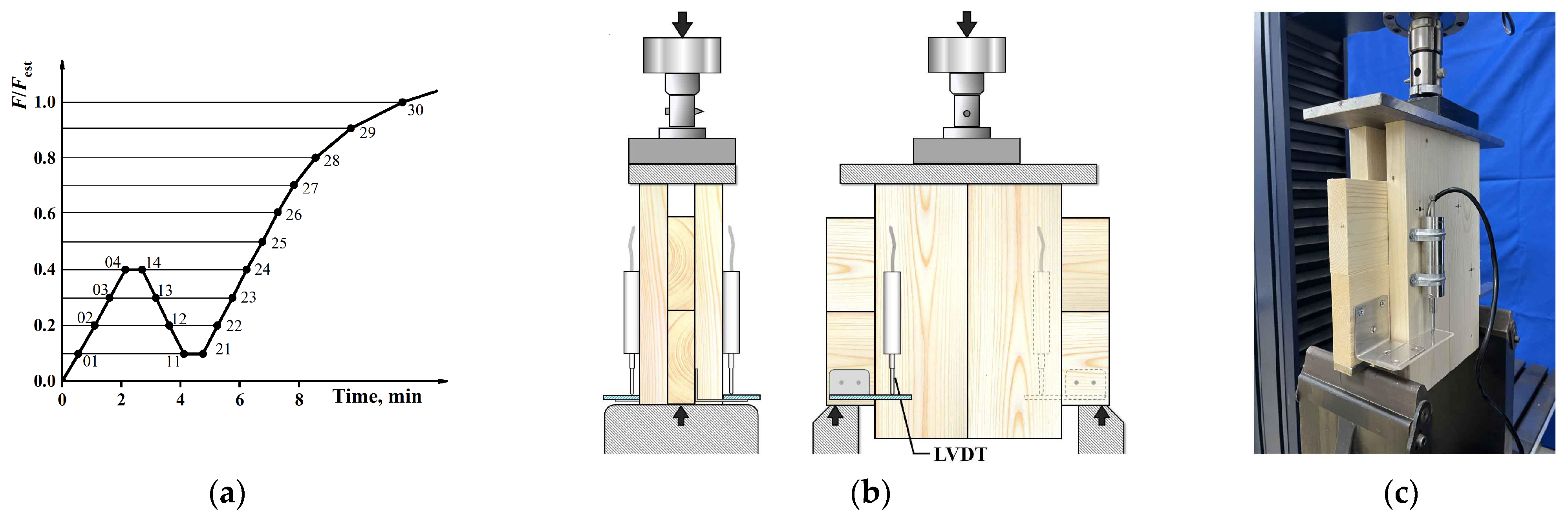
2.3. Testing Procedure and Loading Setup
3. Results and Discussions
3.1. Load–Displacement Characteristics of Multi-Nail Joints
- (1)
- A secant line (Line I) was drawn between the load values of 0.1Pmax and 0.4Pmax, with its slope representing the initial stiffness K0 of the joint;
- (2)
- A second secant line (Line II) was drawn between the load values of 0.4Pmax and 0.9Pmax;
- (3)
- Line II was translated until it was tangent to the curve, forming Line III;
- (4)
- The y-coordinate of the intersection of Line III and Line I represented the yield load Py, while the corresponding x-coordinate indicated the yield displacement δy;
- (5)
- The load value of 0.8Pmax was taken as the ultimate load Pu, with the corresponding x-coordinate as the ultimate displacement δu.
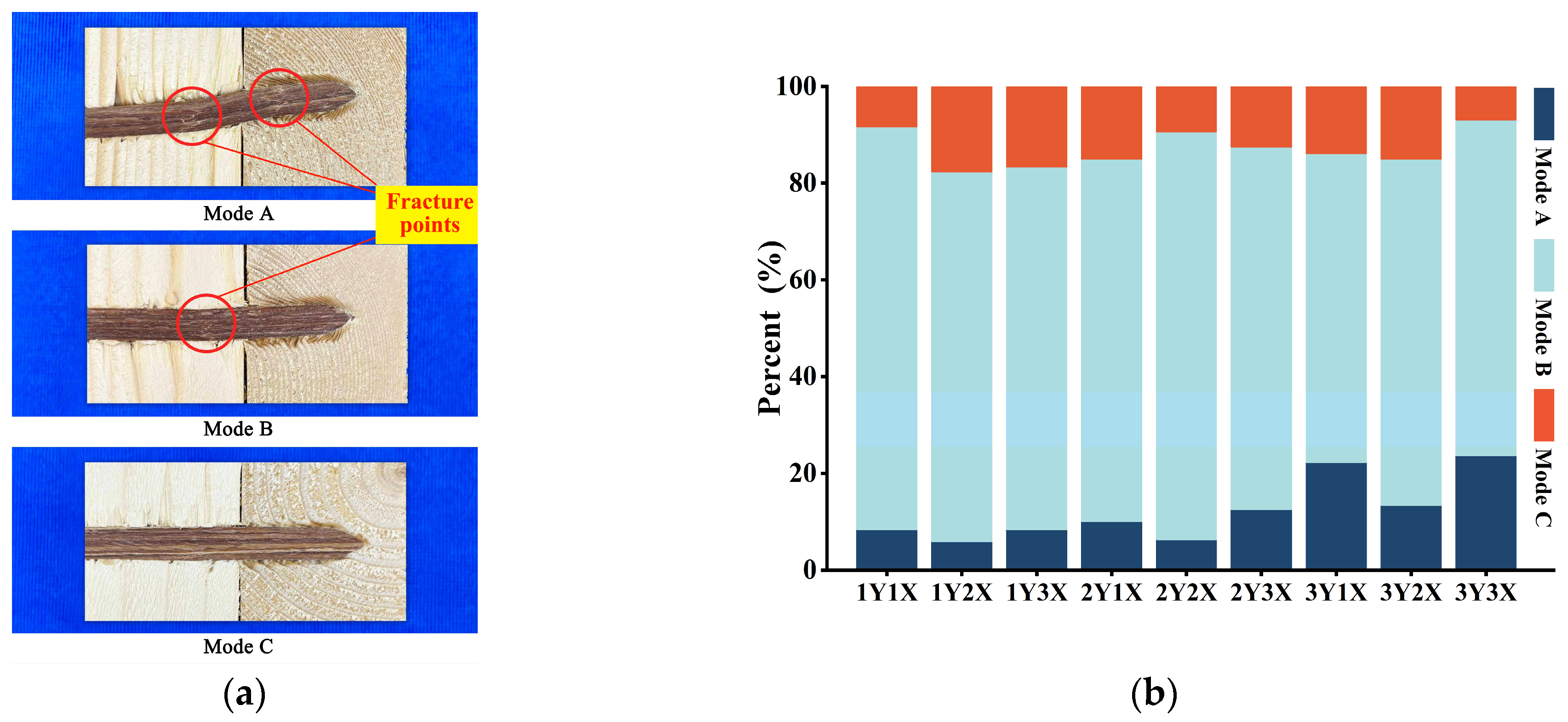
3.2. Failure Characteristics
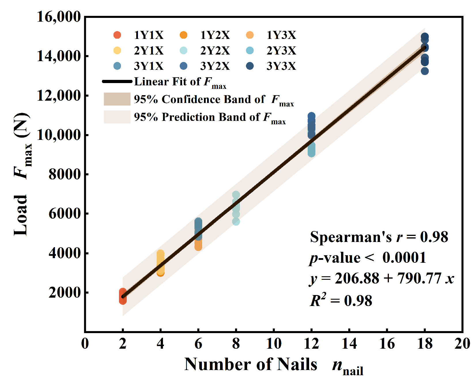
3.3. Maximum Load
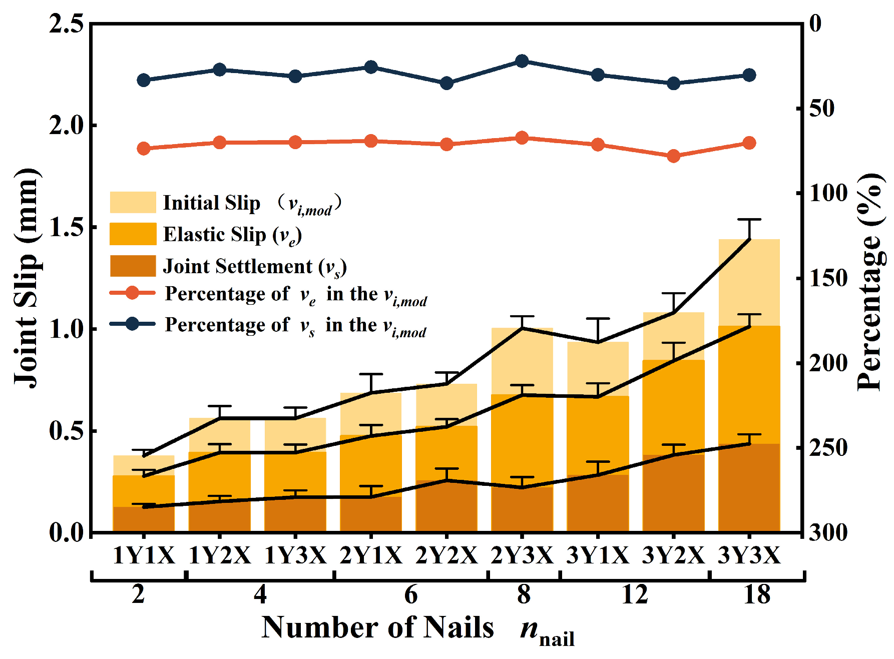
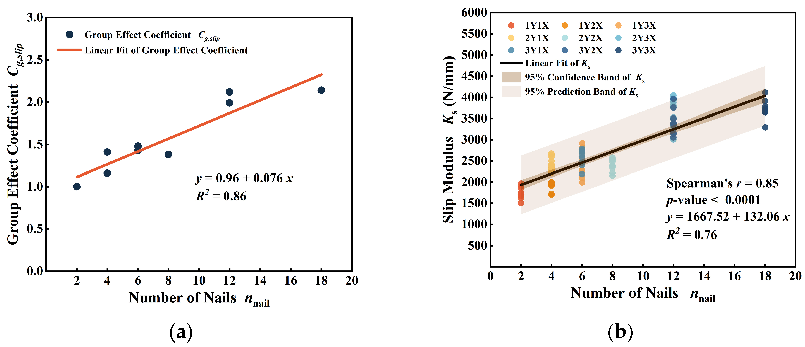
3.4. Slip Modulus
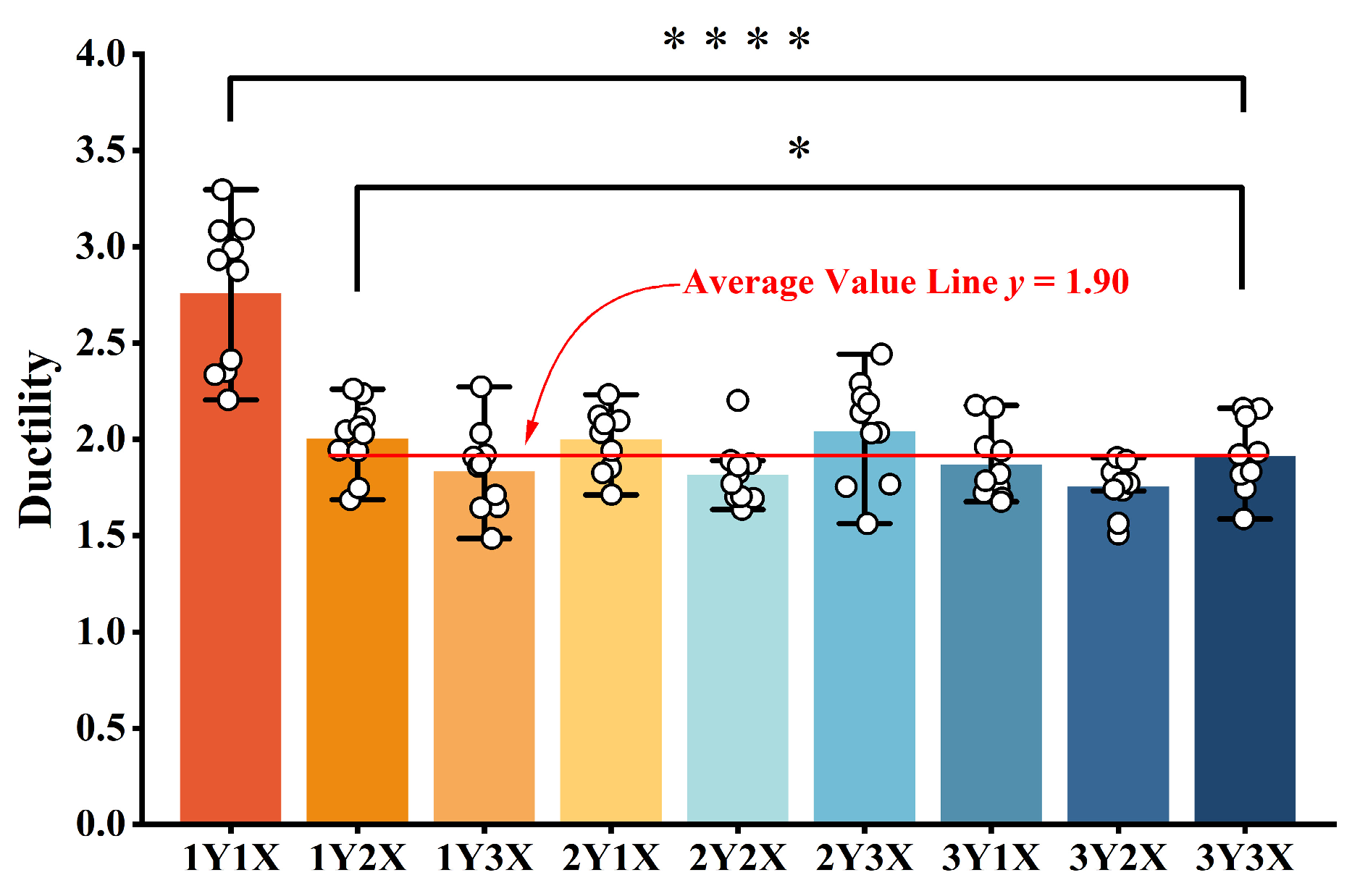
3.5. Ductility
4. Conclusions
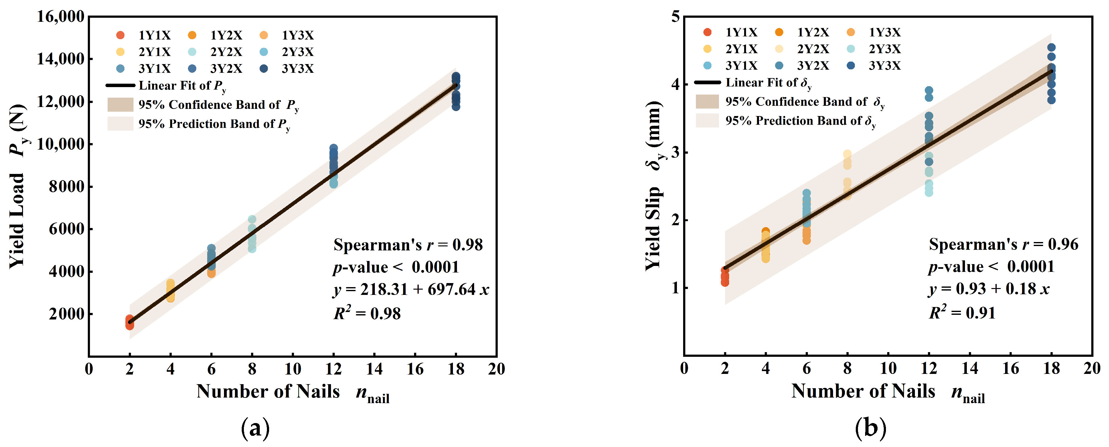
- (1)
- The number of wooden nails exhibits a significant positive correlation with both the yield load and yield displacement, enabling the effective prediction of the structural yield point. This relationship ensures the precise control of the yield load in the design of wooden structures.
- (2)
- The variations in material properties and assembly tightness due to the combination of multilayer boards lead to an uneven stress distribution at different joints. Consequently, the wooden nails experience varying degrees of failure, with failure modes exhibiting a random distribution.
- (3)
- The load-bearing capacity analysis revealed that a consistent arrangement of wooden nails results in a highly stable group effect coefficient, which demonstrates no significant correlation with the number of wooden nails. This stability enhances the predictability of wooden nail connections in NCLT design, thereby facilitating structural optimization and improving the overall reliability.
- (4)
- Spearman correlation analysis revealed a significant positive correlation between the number of wooden nails and the group effect coefficient of the joint slip modulus. Additionally, the theoretical model developed through regression analysis exhibits high accuracy in predicting the slip modulus of wooden nail group connections. An increase in the number of wooden nails effectively enhances the joint’s resistance to deformation and overall stiffness, illustrating the linear accumulation characteristic of the group effect.
- (5)
- Specimens composed of a single orthogonal unit exhibit greater rotational degrees of freedom, resulting in higher slip ductility. In contrast, group connections restrict the slip and rotational freedom through the mutual constraints of multiple orthogonal units. While this arrangement enhances the overall stiffness and stability of the structure, it results in relatively lower ductility, reflecting the suppressive effect of the group effect on structural deformation.
Author Contributions
Funding
Data Availability Statement
Acknowledgments
Conflicts of Interest
References
- Sohier, L. Development of a New Mass Timber Slab: The Dowelled Cross-Laminated Timber. Analytical Design Methods and Experimental Validation. Master’s Thesis, Engineering Faculty, University of Mons, Mons, Belgium, 2018. [Google Scholar]
- Cesar, D.M.P.M.; Pascal, S.L.A.; Thierry, D.; Calil, J.C. Doweled cross laminated timber: Experimental and analytical study. Constr. Build. Mater. 2021, 273, 121820. [Google Scholar] [CrossRef]
- El-Houjeyri, I.; Thi, V.D.; Oudjene, M.; Khelifa, M.; Rogaume, Y.; Sotayo, A.; Guan, Z. Experimental investigations on adhesive free laminated oak timber beams and timber-to-timber joints assembled using thermo-mechanically compressed wood dowels. Constr. Build. Mater. 2019, 222, 288–299. [Google Scholar] [CrossRef]
- Beck Fastening. Available online: https://www.beck-fastening.com/en/news-events/lignoloc-german-design-award-2020 (accessed on 4 April 2025).
- BECK Fastener Group. Available online: https://www.beck-fastening.com/en/innovation/lignoloc (accessed on 26 September 2024).
- Hudert, M.; Elvebakken, M.F.; Meagher, M.; Mangliár, L.; Zhang, X.; Esterle, L. Deep learning enhanced robotic fabrication of timber-to-timber connections with densified hardwood nails. In Proceedings of the IASS Annual Symposia, Beijing, China, 19–23 September 2022. [Google Scholar]
- Han, L.; Pauliny, D.; Sandak, A.; Riggio, M.; Kutnar, A.; Sandberg, D.; Sandak, J. Densified wooden nail for adhesive-and metal-free timber assembles. In Proceedings of the WCTE 2023—2023 World Conference on Timber Engineering, Oslo, Norway, 19–22 June 2023. [Google Scholar] [CrossRef]
- Wang, S.; Wang, F.; Kong, F.; Ma, P.; Chen, Z.; Que, Z. Influence of repeated wetting and drying on withdrawal capacity of wooden nails and metal nails. Constr. Build. Mater. 2023, 409, 133991. [Google Scholar] [CrossRef]
- Gerber, C.; Collado, K.; Morrell, J.J. Impact of moisture cycling on lateral resistance of resin-impregnated compressed beech nails in radiata pine timber. Int. Wood Prod. J. 2021, 12, 147–151. [Google Scholar] [CrossRef]
- Ruan, G.; Filz, G.H.; Fink, G. Master Builders revisited: The importance of feedback loops: A case study using salvaged timber and wooden nails only. Archit. Res. Finl. 2023, 6, 20. [Google Scholar] [CrossRef]
- Stempfer, D. Next Generation of Wooden Nail Firing System. Fasten. Technol. Int. 2019, 42, 132–133. [Google Scholar]
- Wang, S.; Wang, F.; Ma, P.; Kong, F.; Beck, C.; Siemers, S.; Que, Z. Eco-friendly wooden nails: Bonding mechanisms and withdrawal resistance in sustainable timber connections. J. Clean. Prod. 2025, 486, 144606. [Google Scholar] [CrossRef]
- Korte, H.; Koch, G.; Krause, K.; Koddenberg, T.; Siemers, S. Wood nails to fix softwoods: Characterization of structural deformation and lignin modification. Eur. J. Wood Wood Prod. 2018, 76, 979–988. [Google Scholar] [CrossRef]
- Wang, S.; Lin, J.; Wang, F.; Wang, Y.; Kong, F.; Ma, P.; Beck, C.; Que, Z. Mechanical behavior and theoretical modeling of wooden nails under various stress conditions. Constr. Build. Mater. 2025, 458, 139624. [Google Scholar] [CrossRef]
- Vaghefi, N.M.; Mobaraki, B. Evaluation of the effect of explosion on the concrete bridge deck using LS-DYNA. Int. Rev. Civ. Eng. 2021, 12, 135. [Google Scholar] [CrossRef]
- Ruan, G.; Filz, G.H.; Fink, G. Shear capacity of timber-to-timber connections using wooden nails. Wood Mater. Sci. Eng. 2022, 17, 20–29. [Google Scholar] [CrossRef]
- Riggio, M.; Sandak, J.; Sandak, A. Densified wooden nails for new timber assemblies and restoration works: A pilot research. Constr. Build. Mater. 2016, 102, 1084–1092. [Google Scholar] [CrossRef]
- Kunesh, R.H.; Johnson, J.W. Strength of Multiple-Bolt Joints, Influence of Spacing and Other Variables, Rep. T24; Forest Research Laboratory, Oregon State University: Corvallis, OR, USA, 1968. [Google Scholar]
- Gattesco, N.; Toffolo, I. Experimental study on multiple-bolt steel-to-timber tension joints. Mater. Struct. 2004, 37, 129–138. [Google Scholar] [CrossRef]
- Lyu, Y.F.; Li, G.Q.; Wang, Y.B.; Wang, H.L.Z. Bearing behavior of multi-bolt high strength steel connections. Eng. Struct. 2020, 212, 110510. [Google Scholar] [CrossRef]
- Cramer, C.O. Load distribution in multiple-bolt tension joints. J. Struct. Div. 1968, 94, 1101–1118. [Google Scholar] [CrossRef]
- Wilkinson, T.L. Assessment of Modification Factors for a Row of Bolts or Timber Connectors; US Department of Agriculture, Forest Service, Forest Products Laboratory: Madison, WI, USA, 1980. [Google Scholar]
- Fang, Z.; Fang, H.; Huang, J.; Jiang, H.; Chen, G. Static behavior of grouped stud shear connectors in steel–precast UHPC composite structures containing thin full-depth slabs. Eng. Struct. 2022, 252, 113484. [Google Scholar] [CrossRef]
- Ding, J.; Zhu, J.; Kang, J.; Wang, X. Experimental study on grouped stud shear connectors in precast steel-UHPC composite bridge. Eng. Struct. 2021, 242, 112479. [Google Scholar] [CrossRef]
- Kermani, A.; Goh, H. Load-slip characteristics of multi-nailed timber joints. Proc. Inst. Civ. Eng. Struct. Build. 1999, 134, 31–43. [Google Scholar] [CrossRef]
- Hossain, A.; Popovski, M.; Tannert, T. Group effects for shear connections with self-tapping screws in CLT. J. Struct. Eng. 2019, 145, 04019068. [Google Scholar] [CrossRef]
- Zarnani, P.; Quenneville, P. Group tear-out in small-dowel-type timber connections: Brittle and mixed failure modes of multinail joints. J. Struct. Eng. 2015, 141, 04014110. [Google Scholar] [CrossRef]
- Yurrita, M.; Cabrero, J.M. New design model for brittle failure in the parallel-to-grain direction of timber connections with large diameter fasteners. Eng. Struct. 2020, 217, 110557. [Google Scholar] [CrossRef]
- Zarnani, P.; Quenneville, P. New design approach for controlling brittle failure modes of small-dowel-type connections in Cross-laminated Timber (CLT). Constr. Build. Mater. 2015, 100, 172–182. [Google Scholar] [CrossRef]
- Ringhofer, A.; Brandner, R.; Blaß, H.J. Cross laminated timber (CLT): Design approaches for dowel-type fasteners and connections. Eng. Struct. 2018, 171, 849–861. [Google Scholar] [CrossRef]
- EN 1995-1-1; Design of Timber Structures. Part 1-1: General—Common Rules and Rules for Buildings. European Committee for Standardization. CEN: Brussels, Belgium, 2004.
- NDS-2024; National Design Specification® for Wood Construction. AWC: Leesburg, VA, USA, 2024.
- EN 26891; Timber Structures—Joints Made with Mechanical Fasteners—General Principles for the Determination of Strength and Deformation Characteristics. European Committee for Standardization: Brussels, Belgium, 1991.
- EN 1380; Timber Structures—Test Methods—Load Bearing Nails, Screws, Dowels and Bolts. European Committee for Standardization: Brussels, Belgium, 2009.
- Fan, Q.; Yin, Y. Strength of Materials, 3rd ed.; Tsinghua: Beijing, China, 2014. [Google Scholar]
- Yasumura, M.; Kawai, N. Estimating seismic performance of wood-framed structures. In Proceedings of the 5th World Conference on Timber Engineering, Montreux, Switzerland, 17–20 August 1998. [Google Scholar]
- EN 12512; Timber Structures—Test Methods—Cyclic Testing of Joints Made with Mechanical Fasteners. European Committee for Standardization: Brussel, Belgium, 2001.


 | Nail Properties | |
| Nominal length [mm] | 45 | |
| Nominal diameter [mm] | 4.7 | |
| Char. yield moment [N·mm] | 2247 | |
| Char. tensile capacity [N/mm2] | 195.3 | |
| Char. shear resistance [N] | 527.4 | |
| Symbol | 1Y1X | 1Y2X | 1Y3X | 2Y1X | 2Y2X | 2Y3X | 3Y1X | 3Y2X | 3Y3X |
|---|---|---|---|---|---|---|---|---|---|
| Fmax [N] | 1772.93 | 3144.4 | 4710.66 | 3528.08 | 6248.53 | 9422 | 5261.12 | 10,505.49 | 14,204.13 |
| COV [%] | 8.01 | 3.39 | 5.88 | 8.28 | 6.44 | 3.89 | 4.94 | 3.07 | 4.14 |
| nef | 2 | 4 | 6 | 4 | 8 | 12 | 6 | 12 | 18 |
| Fmax/nnail [N] | 886.47 | 786.1 | 785.11 | 882.02 | 781.07 | 785.17 | 876.85 | 875.46 | 789.12 |
| Cg,load | 1.00 | 0.89 | 0.89 | 0.99 | 0.88 | 0.89 | 0.99 | 0.99 | 0.89 |
| Symbol | 1Y1X | 1Y2X | 1Y3X | 2Y1X | 2Y2X | 2Y3X | 3Y1X | 3Y2X | 3Y3X |
|---|---|---|---|---|---|---|---|---|---|
| nnail | 2 | 4 | 6 | 4 | 8 | 12 | 6 | 12 | 18 |
| Ks [N/mm] | 1737.69 | 2007.19 | 2484.45 | 2449.27 | 2397.1 | 3680.7 | 2571.34 | 3464.69 | 3717.07 |
| COV [%] | 8.01 | 10.81 | 12.88 | 6.04 | 5.79 | 11.57 | 7.43 | 9.47 | 5.64 |
| Cg,slip | 1.00 | 1.16 | 1.42 | 1.40 | 1.38 | 2.11 | 1.48 | 1.99 | 2.14 |
Disclaimer/Publisher’s Note: The statements, opinions and data contained in all publications are solely those of the individual author(s) and contributor(s) and not of MDPI and/or the editor(s). MDPI and/or the editor(s) disclaim responsibility for any injury to people or property resulting from any ideas, methods, instructions or products referred to in the content. |
© 2025 by the authors. Licensee MDPI, Basel, Switzerland. This article is an open access article distributed under the terms and conditions of the Creative Commons Attribution (CC BY) license (https://creativecommons.org/licenses/by/4.0/).
Share and Cite
Wang, S.; Lin, J.; Jin, B.; Kong, F.; Ma, P.; Wang, F.; Que, Z. Group Effect on In-Plane Shear Performance in Wooden Nail Connections. Buildings 2025, 15, 1189. https://doi.org/10.3390/buildings15071189
Wang S, Lin J, Jin B, Kong F, Ma P, Wang F, Que Z. Group Effect on In-Plane Shear Performance in Wooden Nail Connections. Buildings. 2025; 15(7):1189. https://doi.org/10.3390/buildings15071189
Chicago/Turabian StyleWang, Shuo, Jingkang Lin, Baolei Jin, Fanxu Kong, Panpan Ma, Feibin Wang, and Zeli Que. 2025. "Group Effect on In-Plane Shear Performance in Wooden Nail Connections" Buildings 15, no. 7: 1189. https://doi.org/10.3390/buildings15071189
APA StyleWang, S., Lin, J., Jin, B., Kong, F., Ma, P., Wang, F., & Que, Z. (2025). Group Effect on In-Plane Shear Performance in Wooden Nail Connections. Buildings, 15(7), 1189. https://doi.org/10.3390/buildings15071189