Article

Stability Analysis of Horizontal Layered Multi-Stage Fill Slope Based on Limit Equilibrium Method

by
Xiaohui Li
1,
Shuaihua Ye
1,*,
Manman Qiu
2,
Weina Ye
3 and
Jingbang Li
3
1
School of Civil Engineering, Lanzhou University of Technology, Lanzhou 730050, China
2
School of Civil Engineering and Water Resources, Qinghai University, Xining 810016, China
3
School of Civil Engineering, Lanzhou Institute of Technology, Lanzhou 730050, China
*
Author to whom correspondence should be addressed.
Buildings 2025, 15(7), 1105; https://doi.org/10.3390/buildings15071105
Submission received: 10 March 2025 / Revised: 24 March 2025 / Accepted: 27 March 2025 / Published: 28 March 2025

Abstract

The stability of a multi-stage fill slope composed of horizontal layered soil is particularly prominent due to its complex structural characteristics, the variability of filler properties, and the combined effects of external environmental factors. Therefore, it is of great significance to clarify whether such slopes are in a safe state. Based on the limit equilibrium method, this paper divides the soil horizontally and obliquely and analyzes the stress and establishes the potential failure mechanism (such as slope toe circle, midpoint circle, etc.) of the multi-stage fill slope in the overall failure mode and local failure mode. The analytical expressions of slope safety factors corresponding to various failure mechanisms are further derived, and the stability analysis process of multi-stage fill slope and the determination method of the most dangerous slip surface are proposed. Through the verification of two examples, the results show that the safety factor obtained by this method is similar to the minimum safety factor obtained by the traditional slice method, and the error is small. At the same time, the most dangerous slip surface and slip range are basically consistent with the traditional method. The research results can provide a theoretical basis and practical reference for stability analysis, filler selection, and engineering design of the fill slope.

1. Introduction

In recent years, with the rapid development of infrastructure construction in western China, large-scale fill projects such as highways, railway subgrades, reservoir dams, and industrial site leveling have been increasing, resulting in a large number of fill slopes. The stability of these slopes is directly related to the safety and durability of the project. However, due to the frequent occurrence of landslides and collapses caused by slope instability, it has a serious impact on regional economic development and people’s lives and health. In particular, the multi-level fill slope is composed of a horizontal layered soil layer; because of its complex structural characteristics, the variability of filler properties, and the combined effect of external environmental factors (such as rainfall, earthquake, etc.), its stability problem is particularly prominent [1,2,3,4,5,6]. Therefore, it is of great significance to clarify whether such slopes are in a safe state for ensuring engineering safety and promoting regional sustainable development.
Many experts and scholars have studied the stability of fill slope by combining theoretical calculation, model test, numerical analysis, and other methods [7,8,9,10,11,12]. In terms of numerical simulation and test, Amena [13] analyzed the applicability of plastic waste-treated clay as embankment filler and used PLAXIS 2D software to analyze the slope stability by the finite element method. Gong et al. [14] studied the disaster-hidden danger of the high and steep original slope-fill slope interface through the indoor model test and compared and analyzed the influence of working conditions such as no weak zone, different thickness of the weak zone, and weakening coefficient with numerical simulation. Taking the loess high fill slope in Lanzhou as an example, Yong et al. [15] evaluated the influence of water content change on slope stability during rainfall through indoor and outdoor tests. The limitation of experiment and numerical simulation lies in the specificity of the results and the dependence on the initial conditions. The theoretical analysis method can reveal the internal mechanism of slope instability and provide a universal theoretical framework and design basis. In this regard, based on the upper bound theorem of limit analysis, Yan et al. [16] constructed an extended three-dimensional horn-shaped failure mechanism for the three-dimensional stability analysis of high slopes with an oblique intersection between the excavation-filling interface and the strike line of the slope surface. By introducing the inclination angle parameter of the excavation-filling interface, the functional equilibrium equation was established, and the sequential quadratic programming optimization algorithm was used to solve the upper bound solution of the slope safety factor after the strength reduction. Mostafaei et al. [17] studied the seismic safety of the abutment of the Bakhtiari double-curvature arch dam, using time-history analysis under DBE and MCE hazard levels. The stability of the wedge is calculated by the Londe limit equilibrium method and MATLAB (R2022b), and the thrust is obtained by ABAQUS. The effects of foundation flexibility, grouting curtain performance, seismic vertical component, material, and geometric nonlinearity on the safety factor were investigated. In addition, Chen et al. [18] combined the limit equilibrium method and the logarithmic spiral curve model to evaluate the seismic stability of the reinforced soil slope and revealed the influence of the uneven distribution of tensile strength on the seismic reinforcement effect. Based on the quasi-static method, Fatehi et al. [19] carried out the limit equilibrium analysis of the reinforced slope under seismic load and discussed the influence of different parameters on the design of the reinforcement layer. Zhang et al. [20] proposed a stability evaluation method of a V-shaped fill slope based on the combination of the limit equilibrium method and quasi-static method and analyzed the influence of seismic load and geometric parameters on the three-dimensional stability and the most dangerous slip surface of the slope. Wang et al. [21] analyzed the probability model of shear strength distribution of typical loess Q2 and Q3 for a high fill project in northern Shaanxi and applied it to the reliability analysis of loess high slope. Huang et al. [22] used the grey correlation analysis method to identify the sensitive factors of high-fill slope stability, which provides a basis for the selection of design parameters. Although the above theoretical analysis of slope stability has been fully carried out, compared with the traditional limit equilibrium method (such as the Bishop method and Morgenstern-Price method), the proposed method has obvious advantages in the calculation of safety factor and the identification of the most dangerous sliding surface by considering the non-uniformity of soil parameters and accurate sliding surface search, and taking into account the overall and local instability. It improves the accuracy and computational efficiency of the analysis and has good engineering practicability.
A large number of calculations and analyses have been carried out on the failure mechanism and stability of the fill slope. However, in the existing research, the fill slope is usually simplified as a homogeneous body, which fails to fully consider the physical characteristics of its layered filling. In fact, the filling part of the fill slope is usually prepared according to the design requirements, and the required degree of compaction is achieved by compaction. However, due to the influence of filling construction technology, there are significant differences in the compaction coefficient of filling soil in different regions, resulting in obvious spatial distribution uncertainty of soil parameters such as unit weight, internal friction angle, and cohesion. In addition, most of the existing research methods on the stability of fill slopes are aimed at single-stage slopes, while there are relatively few studies on the stability of multi-stage slopes. Therefore, it is of great theoretical significance and engineering value to explore the influence of the layered characteristics of the fill slope on the stability, especially the stability of the multi-stage slope.
In summary, aiming at the stability problem of horizontal layered multi-level fill slope, based on the limit equilibrium method, the horizontal slice method and the inclined slice method are used to systematically analyze the failure mechanism that can occur under the overall failure mode and local failure mode of the fill slope. The two typical examples are verified. The calculation results of this method are close to the minimum safety factor obtained by the traditional slice method, the error is small, and the most dangerous slip surface position and slip range determined are basically consistent with the traditional method.

2. Basic Assumption of Sliding Soil and Stress Condition of Soil Strip

2.1. Basic Assumptions

In this paper, the limit equilibrium method is used to analyze the stability of horizontal layered multi-stage filled slope, and the following assumptions are applied:
(1)
The slope soil is an ideal rigid-plastic body;
(2)
The shear strength of slope soil complies with the Mohr–Coulomb criterion;
(3)
Ignore the interaction force between the soil strips taken;
(4)
The slope is a heterogeneous slope and the slip surface is an arc slip surface.
For the circular slip surface, it is assumed that the failure mechanism can be divided into three cases: ① The circular slip surface passes through the slope toe, which is called the slope toe circle; ② The circular slip surface passes through a point outside the toe of the slope, which is called the midpoint circle; ③ The circular slip surface passes through a point on the slope, which is called the slope circle.

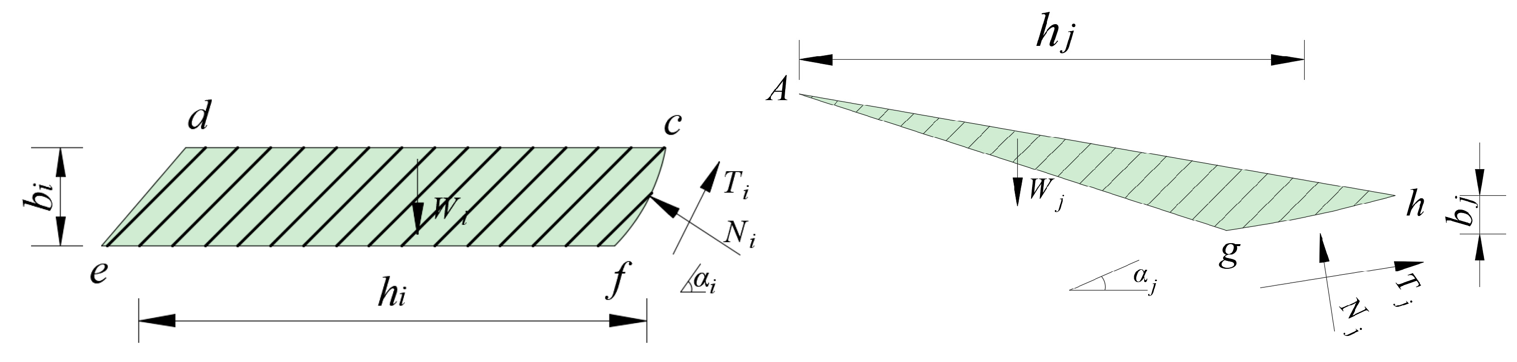
2.2. Stress Condition of Soil Strip

The N-grade slope is taken as an example for analysis, as shown in Figure 1, and the cdef division of the horizontal strip and agh division of the inclined strip are shown in Figure 2. This study takes the heterogeneity of soil slope into consideration. The potential slip surface is circular, the center of the slip surface is O (a,b), and the radius is r. Slope height is H, soil weight is γ , cohesion is c, and internal friction angle is φ .
In the sliding body, a horizontal soil strip i and an inclined soil strip j are selected, and the stress conditions of the soil strip are as follows: the normal stress Ni and the shear stress Ti on the sliding surface of the horizontal soil strip and the weight of the soil strip Wi; the normal stress Nj and shear stress Tj on the sliding surface of the sloping soil strip and the dead weight of soil strip Wj;

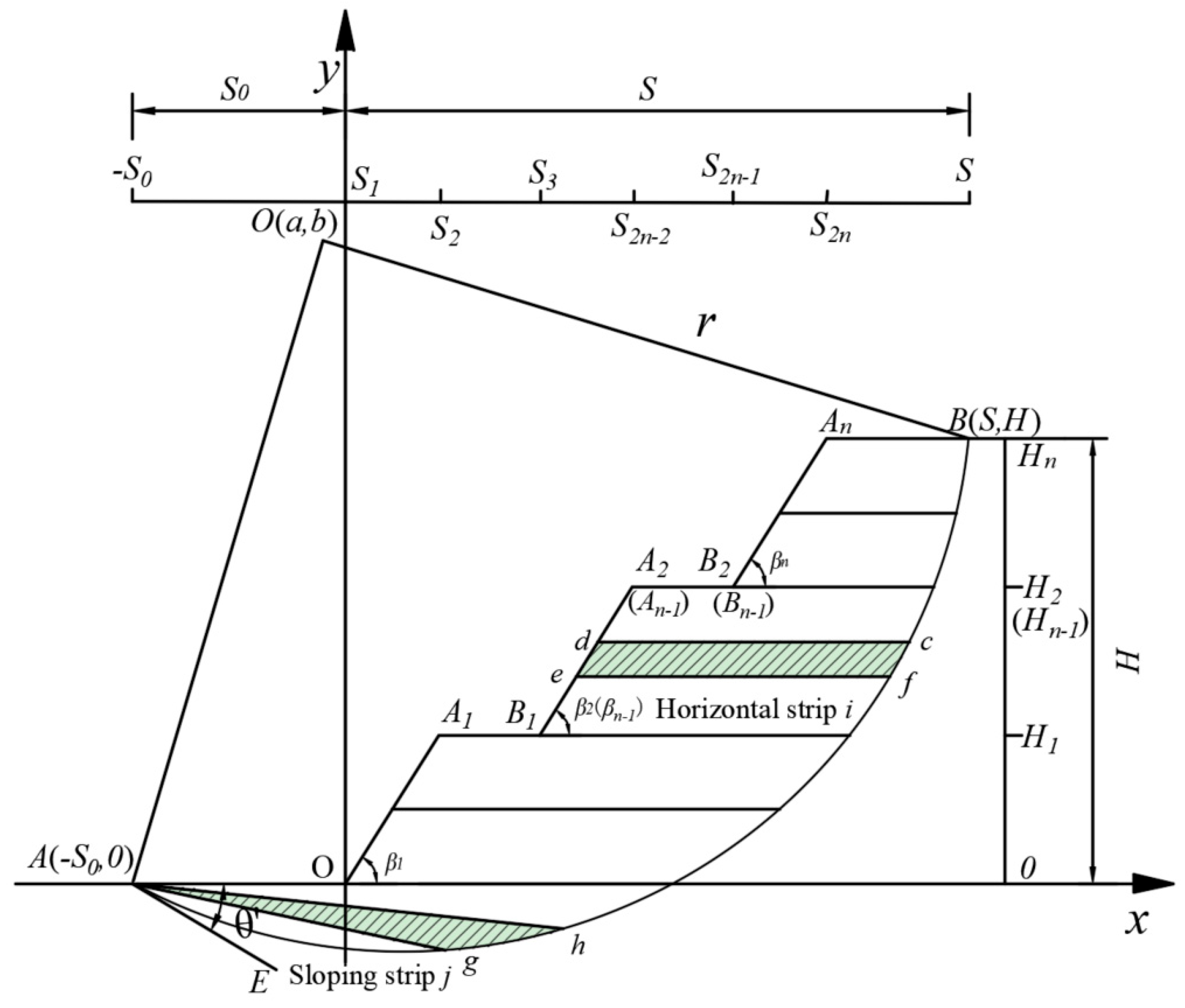
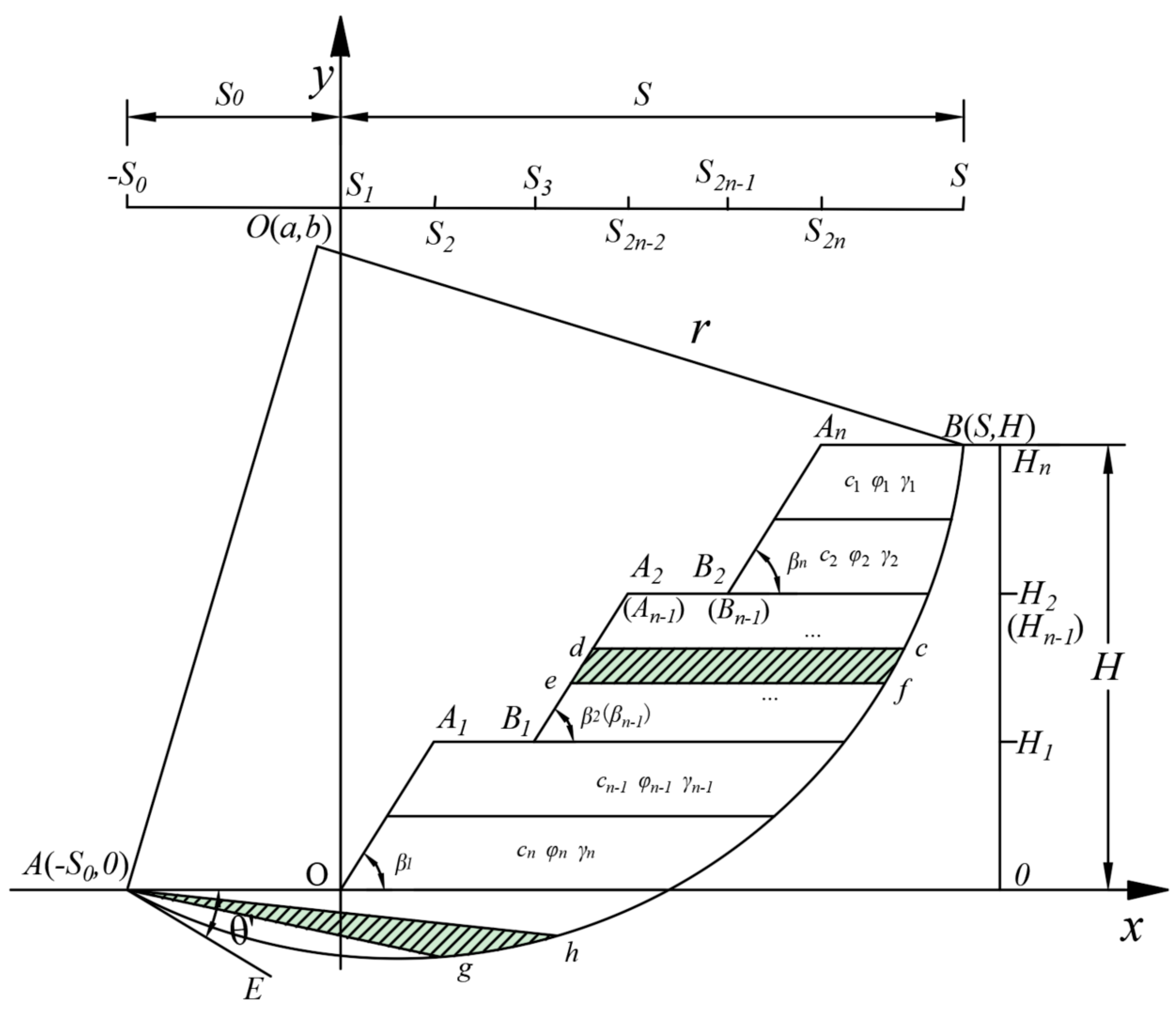
3. Stability Analysis of Multi-Stage Fill Slope Under Overall Failure Mechanism

3.1. Stability Analysis Under Circular Failure Mechanism of Slope Toe

3.1.1. Damage Mechanism

Considering the specific geometric structure of the multi-fill slope, take the N-grade slope AA1B1An−1Bn−1AnD in Figure 3 as an example, where n = 1, 2, 3, … is the slope series, the slope surface is AA1, B1An−1, Bn−1An, the platform width is A1B1, An−1Bn−1, the slope angle is β 1 , β n 1 , β n , the Axy plane rectangular coordinate system is established. The projections of points A, A1, B1, An−1, Bn−1, An, B on the X-axis is successively S1, S2, S3, S2n−2, S2n−1, S2n, S, and the projections of points A, A1(B1), An−1(Bn−1), and An(B) on the Y-axis is successively 0, H1, Hn−1, Hn. The center of the circle is O (a,b), the radius is r, and the arc slip surface is assumed to be AB. The angle between the arc tangent AE and the X-axis through point A is θ , then the slope k = tan ( θ ) of AE, the coordinate of point A is (0,0), and the coordinate of point B is (S,H), where S is the abscissa of the intersection point between the critical slip surface and the slope top plane.
Based on the failure mechanism in Figure 3, the arc slip surface equation AB and the geometric parameters of the equation center O and radius r are given. The equation of the circular slip surface AB of the multi-stage filled slope can be expressed as follows:
x a 2 + y b 2 = r 2
And satisfy:
a 2 + b 2 = r 2 a x 2 + b y 2 = r 2 a = k b
According to Equation (2), it can be obtained:
a = k ( H 2 + S 2 ) 2 H 2 k S b = H 2 + S 2 2 H 2 k S r = 1 + k 2 ( H 2 + S 2 ) 2 H 2 k S
Among them:
S 2 n S k 0 S 2 n S < H k k > 0
At this point, the relationship between S and k can be established. This equation represents the slip surface control condition of the circular failure mechanism of the slope toe. The slip plane of failure is determined by controlling S and k variables.

3.1.2. Stability Analysis

For the calculation and analysis of slope stability under the slope angle circular failure mechanism, the multi-stage fill slope stability analysis and calculation model as shown in Figure 4 is established. The specific derivation process is as follows:
Based on the traditional limit equilibrium method, the sliding soil AA1B1An−1Bn−1AnB is divided into soil strips with a height of bi, and the whole sliding soil is divided into n soil strips. The height of each soil strip can be approximately infinitely small, and the calculation process is simply summed. The soil strip element cdef is arbitrarily taken out for force analysis and calculation. The force diagram of cdef of soil strips is shown in Figure 5. Based on the equilibrium condition of soil strips, it can be obtained as follows:
F x = 0 N i sin α i + T i cos α i = 0 F y = 0 W i N i cos α i T i sin α i = 0
In the formula: W i is the gravity of the i-th soil strip; W i = γ h i b i ; γ is the unit soil weight; h i is the length of the i-th soil strip; N i is the normal stress of the i-th soil strip; T i is the shear stress of the i-th soil strip; α i is the angle between the normal line and the vertical line of the middle point of the bottom edge of the i-soil strip.
For the convenience of calculation, let the equations of line segment AA1, B1An−1, Bn−1An and arc AB be x 1 , x 2 , x 3 , x 4 , respectively, then the stability analysis model of slope angle circle of multi-stage filling edge slope and the governing equation of slip surface can be obtained, as follows:
x 1 = y tan β 1 x 2 = y H 2 tan β 2 + S 2 x 3 = y H 3 tan β 3 + S 3 x 4 = a r 2 ( y b ) 2
From Equation (6) and Figure 4, we can obtain the following:
h i = x 1 x 4 ( 0 y < H 1 ) x 2 x 4 ( H 1 y < H n 1 ) x 3 x 4 ( H 2 y < H n )
The moment balance equation for the center of the circle is established from the soil strip i:
M O = 0 W i d i T i r = 0
In the formula: d is the distance between the center of gravity of the i-th soil strip and the center of the sliding circle, d i = r sin α i h i / 2 .
Since the soil on the sliding surface of the soil strip is in the limit equilibrium state, according to the Mohr–Coulomb criterion:
c i l i + N i tan φ F s t = T i
In the formula: c is the cohesion force of soil on the sliding surface of strip i; φ is the internal friction angle of soil on the sliding surface of strip i; li is the length of the sliding surface of strip i; F s t is the safety factor of slope.
According to Equations (5) and (8), the stability calculation formula of the multi-stage loess fill slope can be obtained as follows:
F s t = i = 1 n c i l i + N i tan φ i r i = 1 n W i d i
It can be seen from the above formula that the established objective function is the minimum safety factor F s t of the slope angle circle of the multi-stage loess fill side slope. When a specific multi-stage slope is given, the objective function is essentially a binary function about S and k, and the corresponding objective function can be described as follows:
F s t , min = min F ( S , k )
When S and k satisfy the Equation (12), F s t , min can obtain the minimum value, and the minimum value of the objective function can be obtained by taking different values of S and k within a reasonable range. According to the obtained S and k, the slip surface corresponding to the minimum value of the safety factor can be determined by substituting it into the Equation (3). At this point, the calculation F s t , min can be converted into a mathematical optimization problem, and the minimum value of the stability coefficient is optimized and solved by MATLAB.
F s t S = F s t k = 0

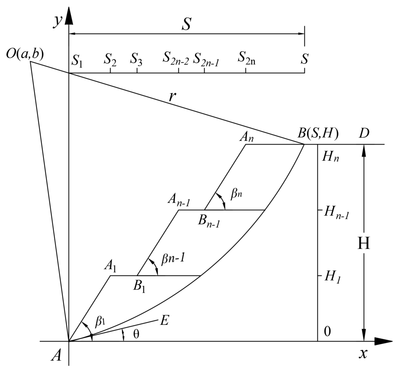
3.2. Stability Analysis Under the Mid-Point Circle Failure Mechanism

3.2.1. Failure Mechanism

In addition to the circular failure mechanism of slope toe mentioned above, the whole failure mechanism of multi-stage loess fill slope may also be a mid-point circle. Similarly, take n-level AA1B1An−1Bn−1AnB as an example, as shown in Figure 6, where n = 1, 2, 3, … is the slope progression. According to the actual engineering situation, θ is always negative. In addition, the meaning of the remaining symbols is the same as before. The specific process is as follows:
In the plane cartesian coordinate system, the center point O is (a,b), point B is (S,H), and S is the abscissa of the intersection point between the critical glide surface and the slope top plane. H is the total slope height. The point F is (−S0,0), where the intersection of the arc BF with the negative half-axis of the X-axis is F, the intersection with the positive half-axis is E, and the projection of the point F on the X-axis is −S0 and the projection on the Y-axis is 0, and its angle with the X-axis is θ . The slope of the line FE is k , and k = tan θ is known by θ .
x a 2 + y b 2 = r 2
And satisfy:
( S 0 a ) 2 + b 2 = r 2 ( S a ) 2 + ( H b ) 2 = r 2 a = ( k b + S 0 )
Among them:
a = S 0 k [ ( S + S 0 ) 2 + H 2 ] 2 H 2 k ( S + S 0 ) b = ( S + S 0 ) 2 + H 2 2 H 2 k ( S + S 0 ) r = 1 + k 2 [ ( S + S 0 ) 2 + H 2 ] 2 H 2 k ( S + S 0 )
At this point, it can be seen from Equation (15) that a relational equation about S , S 0 , k can be established. This equation represents the control condition of the slip surface of the mid-point circular failure mechanism. By controlling S , S 0 , k three variables, the slip surface of failure is determined.

3.2.2. Stability Analysis

For the calculation and analysis of slope stability under the slope angle circular failure mechanism, a multi-stage fill slope stability analysis and calculation model was established, as shown in Figure 7. The specific derivation process is as follows:
For the slope with a general sliding surface, the soil above the toe of the slope is treated by horizontal strips, while the soil below the toe is divided by inclined strips. The soil above the toe of the slope is divided into horizontal soil strips with a height of bi, and the soil below the toe is divided into sloping soil strips with a height of bj. Above the toe of the slope, the calculation process of the slope toe circle is followed; below the toe of the slope, the soil strip element agh is taken for force analysis and calculation. The force diagram of soil strip agh is shown in Figure 8. From the equilibrium condition of the soil strip, the following is obtained:
F x = 0 N j sin α j + T j cos α j = 0 F y = 0 W j N j cos α j T j sin α j = 0
where: W j is the gravity of the soil strip; W j = γ h j b j ; γ is the unit weight of soil; h j is the j soil strip length; N j is the normal stress of the j soil strip. T j is the shear stress of the j soil strip; α j is the angle between the normal line and the vertical line at the midpoint of the bottom edge of the soil strip.
Among them:
h j = 0.5 b j + x = 1 j 1 b x
Soil bar j establishes a moment balance equation for the center of a circle:
M O = 0 W j d j T j r = 0
In the formula: d is the distance between the center of gravity of the j soil strip and the center of the sliding circle, d j = r sin α j h j / 2 .
From Equations (16) and (18), the formula for calculating the stability of sloping soil strips can be obtained:
F s x m = j = 1 n c j l j + N j tan φ j r j = 1 n W j d j
The soil above the toe of the slope is divided into horizontal strips, and the soil below the toe is divided into oblique slices. According to the above Formulas (10) and (19), the F s m final expression of the safety factor of the mid-point circular failure mechanism under the overall failure mode of multi-stage fill slope can be obtained, namely:
F s m = i = 1 n c i l i + N i tan φ i r i = 1 n W i d i + j = 1 n c j l j + N j tan φ j r j = 1 n W j d j
Similarly, it can be seen from the above equation that the objective function of the minimum safety factor F s m of the midpoint circle of a multi-stage filled slope has been established. When a specific multi-stage slope is given, the objective function is essentially a ternary function about S , S 0 , k , and the corresponding objective function can be described as follows:
F s m , min = min F ( S , S 0 , k )
When S , S 0 , k satisfies Formula (22), F s m , min can obtain the minimum value, and the minimum value of the objective function can be obtained by taking different values of S , S 0 , k within a reasonable range, and the slip surface corresponding to the minimum value of the safety factor can be determined by substituting the obtained S , S 0 , k into Formula (15). Similarly, the minimum value of the stability coefficient is optimized by MATLAB.
F s m S = F s m S 0 = F s m k = 0
For the above two kinds of slope failure, when the midpoint circle is S 0 = 0 , the damage will also become the slope toe circle failure. However, through comprehensive analysis, the specific process of the analysis of the two is different, and the conditions to be met are different, so they cannot be classified into one type for discussion and analysis. Therefore, the situation of the midpoint circle and the slope toe circle is necessary to be classified and discussed.

3.3. The Minimum Safety Factor of Multi-Stage Fill Slope Under the Overall Failure Mode

In this paper, two types of sliding surface failure modes of horizontal layered multi-fill slopes are proposed, and the minimum value of slope safety factor F s t , min and F s m , min under the two types of failure modes can be obtained respectively. Therefore, the minimum value of the two results can be obtained by Equation (23), and then the minimum safety factor F g s , min under the overall failure mode of the multi-fill slope can be determined.
F g s , min = min F s t , min , F s m , min

4. Stability Analysis of Multi-Stage Fill Slope Under Local Failure Mechanism

In the multi-stage fill slope, the failure of the slope is not a one-time occurrence, and there will be local damage or deformation in some areas. Due to the uneven thickness of the filling soil layer, the local stress distribution may be uneven, the slope is steep and slow, the slope body is irregular, and there may be local sliding before the overall sliding along the slip zone. In this paper, the local failure modes are divided into two categories: one is the single-stage slope as the local single-stage failure mode; secondly, the multi-stage slope is the local multi-stage (m is the series, 2 ≤ m ≤ n − 1) failure mode. The stability of these two types of local failure modes of multi-stage fill slope will be analyzed in detail.

4.1. Slope Stability Analysis Under Local Single-Stage Failure Mode

Under the local single-stage failure mode, it can be concluded that the local single-stage failure mode can be regarded as the failure mechanism of a single-stage slope. There may be three failure mechanisms of the single-stage slope, as shown in Figure 9: Toe circle (glide surface a), midpoint circle (glide surface b), and slope circle (glide surface c). In the stability analysis of a multi-stage fill slope, the slope toe of each single-stage slope is taken as the origin, the local rectangular coordinate system is established, the possible failure mechanism of each single-stage slope is analyzed, and the minimum value is taken as the minimum safety factor of the single-stage slope. Finally, the minimum safety factor of the multi-stage loess slope under the local single-stage failure mode can be determined by finding the minimum value from the minimum safety factor set of each single-stage slope. This method helps to consider the effects of multiple levels and multiple failure mechanisms on the overall stability.

4.1.1. Damage Mechanism

Taking the i-grade slope as an example, the schematic diagram of the failure mechanism shown in Figure 10 is established, and the arc slip surface equations of different control failure mechanisms and the center and radius of the geometric parameters of the equation are given.
(1) Toe circle of slope
Based on the failure mechanism in Figure 10a, a local plane rectangular coordinate system O x y is established, whose center O is ( a , b ) , arc radius is r i , the point C i is ( S i , λ i H ) , the point B i is (0,0), and the slope of the line B i E is k i .
Then, the equation of arc C i B i is as follows:
( x a i ) 2 + ( y b i ) 2 = r 2
Among them:
a i = k i ( S i 2 + λ i 2 H 2 ) 2 k i S i 2 λ i H b i = S i 2 + λ i 2 H 2 2 λ i H 2 k i S i r i = 1 + k i 2 ( S i 2 + λ i 2 H 2 ) 2 λ i H 2 k i S i
(2) Midpoint circle
Based on the failure mechanism in Figure 10b, a local plane rectangular coordinate system O x y is established, point F is ( S i , 0 ) , line FE slope is k i , and k i < 0 .
Then, the equation of arc C i F is as follows:
( x a i ) 2 + ( y b i ) 2 = r 2
Among them:
a i = S i k i [ ( S i + S i ) 2 + λ i 2 H 2 ] 2 λ i H 2 k i ( S i + S i ) b i = ( S i + S i ) 2 + H 2 2 λ i H 2 k i ( S i + S i ) r i = 1 + k i 2 [ ( S i + S i ) 2 + λ i 2 H 2 ] 2 λ i H 2 k i ( S i + S i )
(3) Arc-shaped sliding surface on a slope
Based on the failure mechanism in Figure 10c, a local plane rectangular coordinate system O x y is established, point G is ( S i , S i tan β i ) , and the slope of line GE is k i .
Then the equation of the arc G i G is as follows:
( x a i ) 2 + ( y b i ) 2 = r i 2
Among them:
a i = S k i ( S i S i ) 2 + k i ( λ i H S i tan β i ) 2 ] 2 ( λ i H S i tan β i ) 2 k i ( S i S i ) b i = ( S i S i ) 2 + λ i 2 H 2 S i tan β i [ S i tan β i + 2 k i ( S i S i ) 2 ( λ i H S i tan β i ) 2 k i ( S i S i ) r i = 1 + k i 2 [ ( S i S i ) 2 + ( λ i H S i tan β i ) 2 ] 2 ( λ i H S i tan β i ) 2 k i ( S i S i )

4.1.2. Stability Analysis

(1) Toe circle of slope
F 1 s t = i = 1 n ( c i l i + N i tan φ i ) r i = 1 n W i d i
where a i , b i , r i expressions are brought in by Equation (25).
Assuming that the minimum safety factor F 1 s t for the circular failure mechanism at the toe of the i-th slope under the local single-stage failure mode has already been established, the objective function is essentially a binary function related to Si and ki. In that context, the corresponding objective function can be described as follows:
F 1 s t , min = min F 1 s t ( S i , k i )
When Si and ki satisfy Equation (32), F 1 s t can achieve its minimum value. By varying Si and ki within a reasonable range, the minimum value of the objective function can be obtained.
F 1 s t S i = F 1 s t k i = 0
(2) Midpoint circle
F 1 s m = i = 1 n ( c i l i + N i tan φ i ) r i = 1 n W i d i + j = 1 n ( c j l j + N j tan φ j ) r j = 1 n W j d j
where a i , b i , r i expressions are brought in by Equation (27).
Similarly, the minimum value F 1 s m of the safety factor corresponding to the mid-point circle failure mechanism of the i-grade slope in the local single-stage failure mode has been established, and the objective function is essentially a ternary function about S i , S i , k i , so the corresponding objective function can be described as follows:
F 1 s m , min = min F 1 s m ( S i , S i , k i )
When S i , S i , k i satisfies Equation (35), F 1 s m can obtain the minimum value, and S i , S i , k i can obtain the minimum value of the objective function by taking different values within a reasonable range.
F 1 s m S i = F 1 s m S i = F 1 s m k i = 0
(3) Arc-shaped sliding surface on a slope
F 1 s s = i = 1 n ( c i l i + N i tan φ i ) r i = 1 n W i d i
where a i , b i , r i expressions are brought in by Equation (29).
Similarly, the minimum value of the safety factor F 1 s s corresponding to the circular failure mechanism of the i-grade slope in the local single-stage failure mode has been established, and the objective function is essentially a ternary function about S i , S i , k i , so the corresponding objective function can be described as follows:
F 1 s s , min = min F 1 s m ( S i , S i , k i )
When S i , S i , k i satisfies Equation (38), F 1 s s can obtain the minimum value, and the minimum value of the objective function can be obtained by taking different values within a reasonable range of S i , S i , k i .
F 1 s s S i = F 1 s s S i = F 1 s s k i = 0
Through the calculation of the above three failure mechanisms, the minimum safety factor F 1 s i , min of the i-grade slope under the local single-stage failure mode can be determined by Equation (39).
F 1 s i , min = min F 1 s t , min , F 1 s t , min , F 1 s s , min
Through the above method, F 1 s t , min is calculated for each level of slope in turn. Finally, the minimum safety factor F 1 s , min of the multi-stage fill slope under the local single-stage failure mode can be determined by Equation (40):
F 1 s , min = min F 1 s 1 , min , F 1 s 2 , min , , F 1 s n , min

4.2. Slope Stability Analysis Under Local Multi-Stage Failure Mode

The stability analysis model under the local multi-stage failure mode is shown in Figure 11. Using the above method, m = 2, 3, … When n − 1, the local minimum safety factor F 1 s , min , F 2 s , min , , F ( n 1 ) s , min of the multi-stage fill slope is obtained.

5. Multi-Stage Fill Slope Stability Analysis Process

In order to more intuitively represent the slope stability analysis process in this paper, the multi-stage fill slope stability analysis flow chart as shown in Figure 12 is drawn, and the analysis process is carried out during the stability analysis.

6. Example Verification
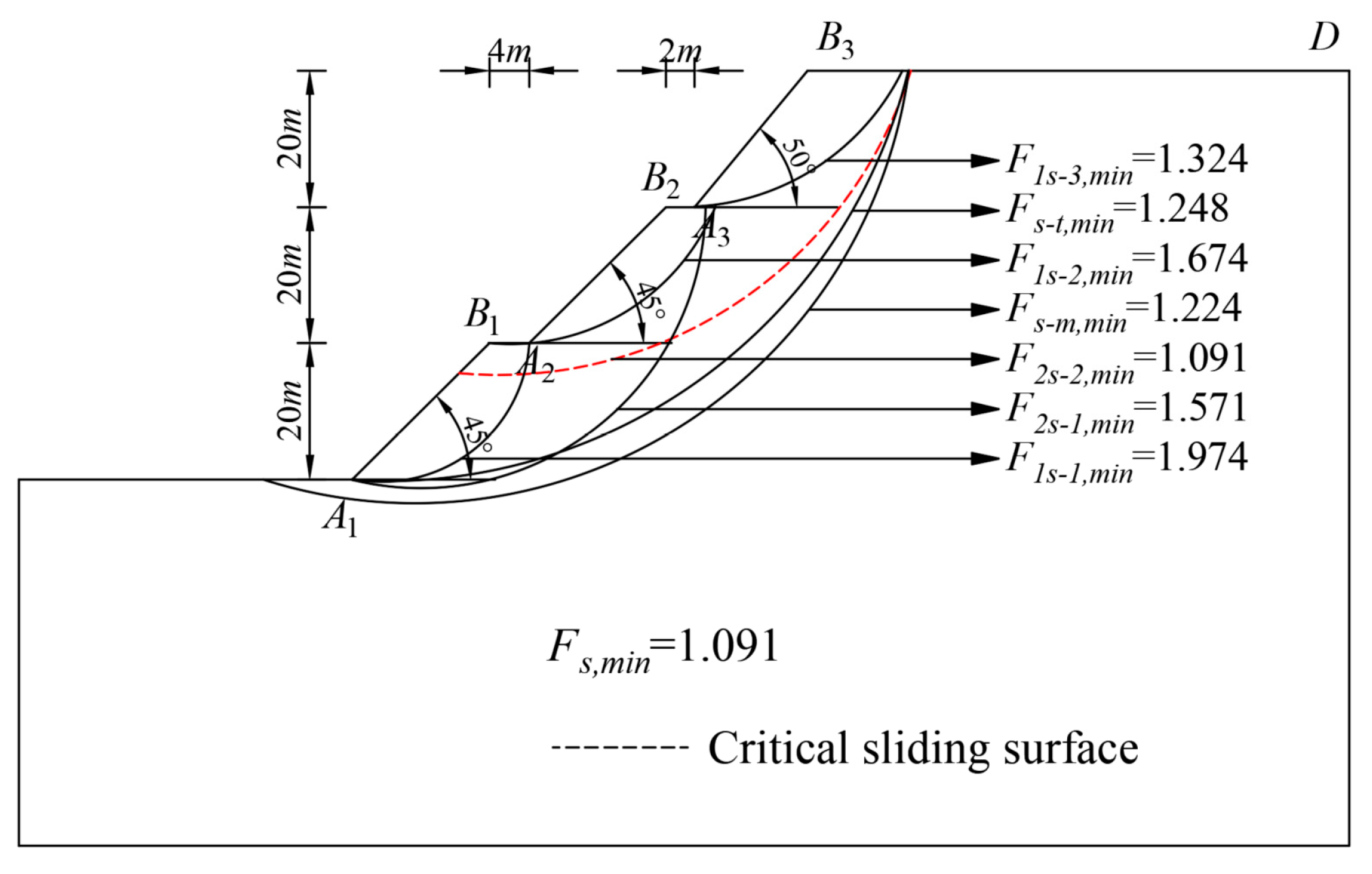
6.1. Example 1

In order to verify the correctness of the derived formula, the calculated results in this paper are compared with those calculated by Deng Dongping, Gao Liansheng, and the traditional strip method, as shown in Table 1. The ratio of slope potential slip face corresponding to the slope safety factor Fs is shown in Figure 13.
Comparing the calculation methods of the safety factor when local instability occurs in the three-level slope, the total height of the slope if H = 60 m, the height of the first-, second-, and third-grade slopes are 20 m, the platform width d1 = 4 m, d2 = 2 m. Side slope toe β 1 = β 2 = 45 ° , β 3 = 50 ° . Cohesion c = 32 kPa, internal friction angle φ = 28 ° , unit weight of soil γ = 18.7 kN / m 3 . As shown in Figure 14, the calculated minimum safety factor of the slope is 1.091. The potential slip-face ratio of the slope is shown in Figure 15.

6.2. Example 2

It is known that a third-stage heterogeneous fill slope project is a third-stage heterogeneous fill slope composed of 5 layers of soil, and the material parameters are shown in Table 2. The total height of the slope is H = 30 m, the height of the first, second, and third slopes is 10 m, the width of the platform is d1 = 3 m, d2 = 3 m, and the slope toe of the slope surface β 1 = β 2 = β 3 = 45 ° .

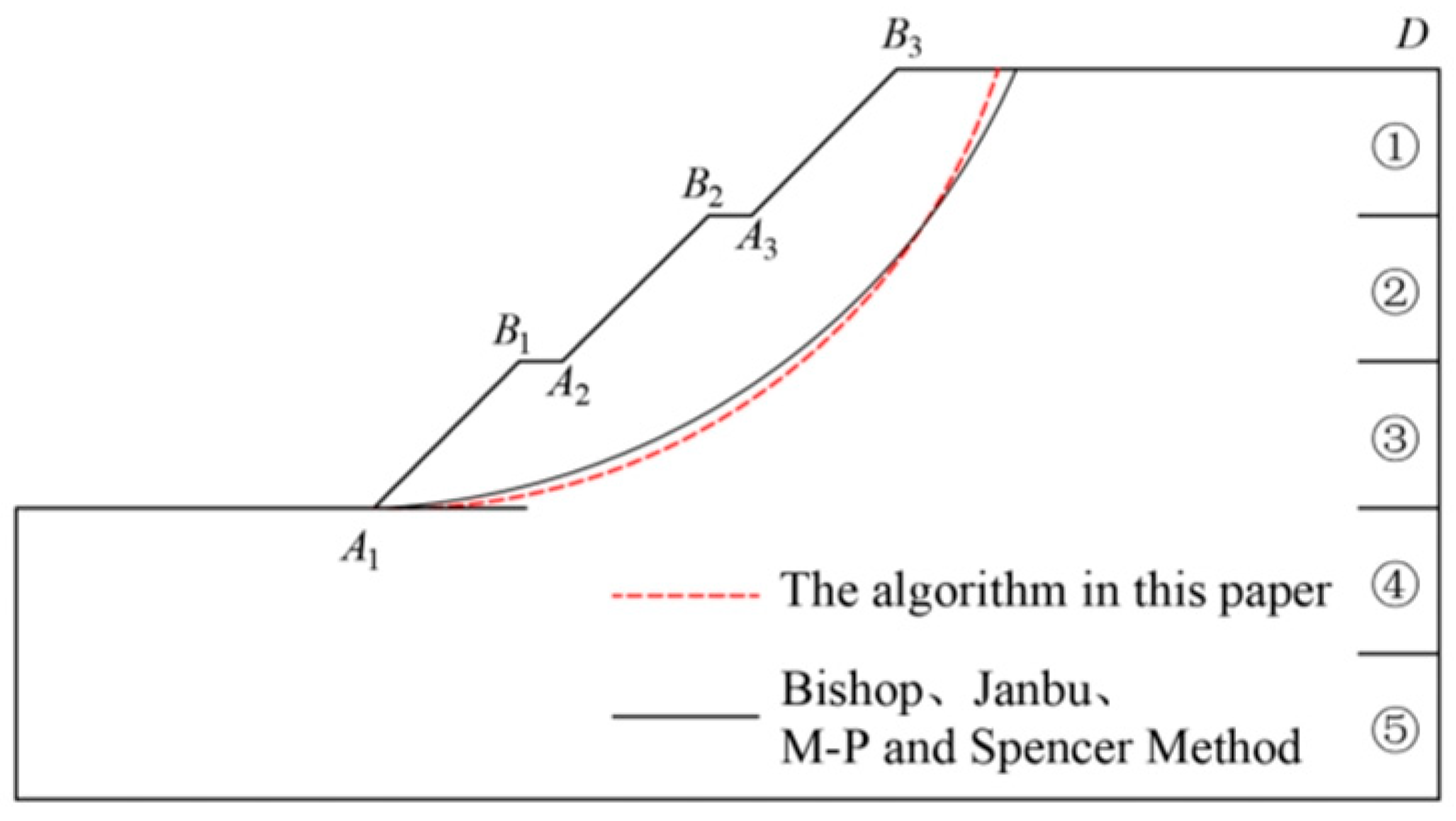
6.2.1. Algorithm in This Study

The limit equilibrium method proposed in this paper is used to analyze the stability of a horizontal layered multi-stage filled slope, and the specific calculation results are shown in Figure 16.

6.2.2. Traditional Strip Method

For this calculation example, the traditional strip method is used for stability analysis and calculation, and the SLOPE/W module is used for slope stability analysis. In Geo Studio, the M-P method, Bishop method, Janbu method, and Spencer method (collectively referred to as the traditional strip method) were used to solve the minimum safety factor of the multi-stage fill slope and the coordinate radius of the circle center, as shown in Table 3.

6.2.3. Comparative Analysis

The above two methods were used to calculate the stability of example 2. The specific comparison results are shown in Table 4 and Figure 17. It can be seen from Table 4 that the relative deviations of the minimum safety factor obtained by the proposed algorithm and the traditional slice methods in Geo Studio are −0.4%, 3.5%, −3.8%, and −3.8%, respectively. It can be seen that the calculation and analysis methods in this chapter have little difference compared with the results of the traditional slice method and all meet the requirements of the specification. It can be shown that the method in this chapter has a certain rationality.

7. Conclusions

This paper conducts a horizontal and inclined slice analysis of soil based on the limit equilibrium method and performs a stress analysis. It establishes potential failure mechanisms, such as toe circles and midpoint circles, for multi-stage fill slopes under both global and local failure modes. The main conclusions are as follows:
(1) The method in this paper not only considers the overall instability failure of multi-stage fill slope but also considers the local instability failure and provides an analysis process that can comprehensively analyze the stability of multi-stage fill slope.
(2) The comparative analysis of the calculation results obtained by the horizontal minimum safety factor between the two is not more than 5%, and the obtained most dangerous sliding surface is basically the same, which can prove the rationality of the proposed method.
(3) The method presented in this paper can be applied to the stability calculation of all kinds of heterogeneous and homogeneous single-stage and multi-stage slopes, and the influence of geometric parameters and soil parameter values on slope stability can be considered, providing a certain reference for the stability research of multi-stage fill slopes.

Author Contributions

Conceptualization, X.L.; Methodology, X.L. and S.Y.; Validation, S.Y. and W.Y.; Investigation, M.Q.; Data curation, M.Q. and J.L.; Resources, S.Y.; Writing—original draft, X.L. and M.Q.; Writing—review and editing, S.Y., W.Y. and J.L. All authors have read and agreed to the published version of the manuscript.

Funding

This research was funded by the National Natural Science Foundation of China (Grant No. 52168050), the Gansu Province Higher Education Teacher Innovation Fund Project (Grant No. 2025A-231), the Gansu Province Science and Technology Plan Project (Grant No. 24JRRA292), the Gansu Provincial Department of Education Young Doctor Support Project (Grant No. 2023QB-048).

Data Availability Statement

Some or all data, models, or codes that support the findings of this study are available from the corresponding author upon reasonable request.

Conflicts of Interest

The authors declare that they have no known competing financial interests or personal relationships that could have appeared to influence the work reported in this paper.

References

  1. Yang, Z.; Cheng, X. High Fill Slope Collapse: Stability Evaluation Based on Finite Element Limit Analyses. Transp. Geotech. 2024, 44, 101156. [Google Scholar]
  2. Mei, Y.; Zhou, D.; Hu, C.; Wang, X.; Zhang, Y.; Xiao, N.; Shi, W. Study on Deformation Characteristics of Loess Ultrahigh-Fill Slope Based on Large-Scale Undisturbed Soil Centrifugal Model Tests. Front. Earth Sci. 2022, 10, 848542. [Google Scholar]
  3. Jin, L.; Liao, Y. Upper Bound Analysis of Two-Layered Slopes Subjected to Seismic Excitations Using the Layer-Wise Summation Method. Buildings 2024, 14, 1990. [Google Scholar] [CrossRef]
  4. Zhang, F.; Jia, S.; Gao, Y. Stability Analysis of Cut-Fill and Deep Patch Unsaturated Slopes Under Steady Infiltration Conditions. Sci. China Technol. Sci. 2025, 68, 1120701. [Google Scholar]
  5. Wu, Y.; Zhou, X.; Liu, J. Long-Term Performance of the Water Infiltration and Stability of Fill Side Slope against Wetting in Expressways. Appl. Sci. 2022, 12, 5809. [Google Scholar] [CrossRef]
  6. Yao, Y.; Zhang, J.; Li, X.; Tu, Y.; Zhong, Z. The Stability of Slopes and Building Structures Using an Energy Visualization Procedure. Buildings 2024, 14, 3705. [Google Scholar] [CrossRef]
  7. Ren, Y.; Li, T.; Yang, L.; Wei, D.; Tang, J. Stability Analysis of Ultra-High-Steep Reinforced Soil-Filled Slopes Based on Centrifugal Model Tests and Numerical Calculation. Chin. J. Geotech. Eng. 2022, 44, 836–844. [Google Scholar]
  8. Ye, S.; Zhuang, Y.; Fang, G. Stability Factors and Deformation Law of Loess High Fill Slope. J. Lanzhou Univ. Technol. 2021, 47, 120–126. [Google Scholar]
  9. Liu, X.; Song, B.; Sun, Z.; Jiao, W. Critical Filling Height of Embankment over Soft Soil: A Three-Dimensional Upper-Bound Limit Analysis. Buildings 2025, 15, 395. [Google Scholar] [CrossRef]
  10. Renaud, V.; Al Heib, M.; Muller, R.; Burda, J. Long-Term Slope Stability of Abandoned Mine Lake—Numerical Modelling and Risk Assessment. Mater. Proc. 2021, 5, 88. [Google Scholar] [CrossRef]
  11. Zhang, H.; Zhang, C.; Zheng, W.; Wang, X.; Zhang, J. Analysis of the Stability of a High Fill Slope under Different Gradients and Precipitation Conditions. Appl Sci. 2024, 14, 7590. [Google Scholar] [CrossRef]
  12. Li, Z.; Sun, L.; Liu, L.; Guan, C. Research on Safety Evaluation Method of High-Fill Slope Considering Heterogeneity and Anisotropy. Bull. Eng. Geol. Environ. 2022, 81, 275. [Google Scholar]
  13. Amena, S. Analysis of the Stability of Reinforced Plastic Waste Treated Clay as Embankment Fill on Soft Soils. Adv. Civ. Eng. 2022, 2022, 1831970. [Google Scholar]
  14. Gong, W.; Zhang, X.; Pei, X.; Chen, L.; Jiang, R.; Sun, H.; Zhong, Y. Instability Modelling of Loess Fill Slope with Influence of Weak Zone of High and Steep Filling Interface. J. Eng. Geol. 2023, 31, 288–298. [Google Scholar]
  15. Yong, X.; Zhang, Y.; Hou, Y.; Han, B.; An, N.; Zhang, H.; Ma, Y. Stability of Loess High-Fill Slope Based on Monitored Soil Moisture Changes. Res. Cold Arid Reg. 2023, 15, 191–201. [Google Scholar]
  16. Yan, C.; Wang, H. Three-Dimensional Stability of Slopes with Cut-Fill Interface Based on Upper-Bound Limit Analysis. Chin. J. Geotech. Eng. 2024, 46, 174–181. [Google Scholar]
  17. Mostafaei, H.; Behnamfar, F.; Alembagheri, M. Nonlinear analysis of stability of rock wedges in the abutments of an arch dam due to seismic loading. Struct. Monit. Maint. 2020, 7, 295–317. [Google Scholar]
  18. Chen, X.; Zhou, Z.; Zhu, Y.; Pu, S.; Zhang, D.; Li, E. Evaluating Seismic Stability of Reinforced Soil Slopes Using the Limit Equilibrium Method: Influence of Geosynthetic Strength Indicators. Front. Phys. 2025, 12, 1526223. [Google Scholar]
  19. Fatehi, M.; Hosseinpour, I.; Jamshidi Chenari, R.; Payan, M.; Javankhoshdel, S. Deterministic Seismic Stability Analysis of Reinforced Slopes Using Pseudo-Static Approach. Iran. J. Sci. Technol. Trans. Civ. Eng. 2023, 47, 1025–1040. [Google Scholar]
  20. Zhang, F.; Jia, S.; Shu, S. Effects of Seismic Amplification on the 3D Stability of Fill Slopes in V-Shaped Valleys. Acta Geotech. 2024, 19, 3241–3255. [Google Scholar]
  21. Wang, X.; Yuan, Y.; Zhang, S. Reliability Analysis of Natural High Loess Slope and Backfill Slope in Northern Shanxi area. J. Xi’an Univ. Archit. Technol. 2021, 53, 665–672. [Google Scholar]
  22. Huang, A.; Ye, S. Sensitivity of High Fill Slope Stability Factors Under Seismic Conditions. Soil Mech. Found. Eng. 2020, 57, 356–363. [Google Scholar]
Figure 1. Calculation model of multi-stage fill slope.
Buildings 15 01105 g001
Figure 2. Stress analysis of horizontal and sloping soil strips.
Buildings 15 01105 g002
Figure 3. Multi-stage filling edge slope angle circle failure mechanism.
Buildings 15 01105 g003
Figure 4. Calculation model of the stability analysis of the angle circle of the multi-stage filling slope.
Buildings 15 01105 g004
Figure 5. Schematic diagram of soil strip element cdef force.
Buildings 15 01105 g005
Figure 6. Mid-point circular failure mechanism of multi-stage filled slope.
Buildings 15 01105 g006
Figure 7. Stability analysis and calculation model of the mid-point circle of multi-stage fill slope.
Buildings 15 01105 g007
Figure 8. Schematic diagram of agh force on soil strip.
Buildings 15 01105 g008
Figure 9. Stability analysis model of multi-stage fill slope under local single-stage failure mode.
Buildings 15 01105 g009
Figure 10. Schematic diagram of the failure mechanism of the i-th grade slope.
Buildings 15 01105 g010aBuildings 15 01105 g010b
Figure 11. Stability analysis model of multi-stage fill slope under local multi-stage failure mode.
Buildings 15 01105 g011
Figure 12. Stability analysis flow chart of horizontal layered multi-stage fill slope.
Buildings 15 01105 g012
Figure 13. Schematic diagram of the critical slip surface determined by different methods.
Buildings 15 01105 g013
Figure 14. Slope stability analysis results of the proposed algorithm.
Buildings 15 01105 g014
Figure 15. Schematic diagram of the critical slip surface determined by different methods.
Buildings 15 01105 g015
Figure 16. Stability results of the third-grade fill slope calculated by the method presented in this paper.
Buildings 15 01105 g016
Figure 17. Critical slip plane determined by different stability analysis results.
Buildings 15 01105 g017
Table 1. Comparison of stability analysis results by different methods.
Calculation MethodCenter of a Circle (a,b)Radius r/mSafety Factor Fs,min
Bishop method(22.564, 37.182)25.9722.288
Janbu method(22.319, 37.408)25.8842.107
The algorithm in this paper(22.385, 37.047)25.8172.124
Deng Dongping--2.197
Gao Liansheng--2.072
Table 2. Soil material parameters.
Soil Layer Numbering c / ( k P a ) φ / ( ° ) γ / ( k N / m 3 )
① Crushed stone27.638.520.2
② Sandy soil I27.028.019.0
③ Sandy soil II19.325.019.0
④ Silty clay I15.333.018.5
⑤ Silty clay II17.225.019.5
Table 3. Stability analysis results of the slope with the traditional strip method.
Calculation MethodCenter of a Circle (a,b)Radius r/m Safety Factor Fs,min
Bishop method(89.28, 80.125)61.041.384
Janbu method(89.28, 80.125)61.041.297
M-P method(89.28, 80.125)61.041.395
Spencer method(89.28, 80.125)61.041.395
Table 4. Comparison of different stability analysis results.
Calculation MethodSafety Factor Fs,minMinimum Relative Deviation of Safety Factor
The algorithm in this paper1.342 -
Bishop method 1.348 −0.4%
Janbu method 1.297 3.5%
M-P method 1.395 −3.8%
Spencer method 1.395 −3.8%
Disclaimer/Publisher’s Note: The statements, opinions and data contained in all publications are solely those of the individual author(s) and contributor(s) and not of MDPI and/or the editor(s). MDPI and/or the editor(s) disclaim responsibility for any injury to people or property resulting from any ideas, methods, instructions or products referred to in the content.

