
Numerical Investigations of Reinforced Concrete Slabs Subjected to Contact Explosions


Abstract
1. Introduction
2. Preliminary Numerical Modelling and Verification
2.1. Model Verification
2.2. Model Description
2.3. Material Models
2.4. Result Comparison
3. Blast Load Field Tests
3.1. Specimen Description
3.2. Test Setup
3.3. Experimental Slab Damage
4. Calibration and Validation of Numerical Model
4.1. Model Description of Experimental Test
4.2. Simulation Results
4.3. Damage Analysis
5. Parametric Analysis
6. Conclusions
- Experimental Findings
- -
- A contact explosion resulted in localised damage characterised by a circular perforation and an hourglass-shaped damage profile without severely compromising structural integrity.
- -
- Reinforcement bars were bent and experienced significant plastic deformation but retained continuity, confirming their capacity to absorb and redistribute explosive energy without fracturing.
- Numerical Model Validation
- -
- The developed numerical model successfully replicated the experimental results when calibrated with an instantaneous geometric strain (IGS) erosion parameter of 0.375.
- -
- Lower IGS values led to widespread damage, while higher values localised the damage around the contact area, aligning more closely with experimental observations.
- -
- The only setback observed is that the numerical simulations cannot replicate the identical hourglass shape of the perforation, no matter which parameter is modified. Regardless, if approximate damage in terms of perforation diameter and damaged area is obtained, it is possible to assess the global condition of the structural element after the contact explosion.
- Parametric Analysis
- -
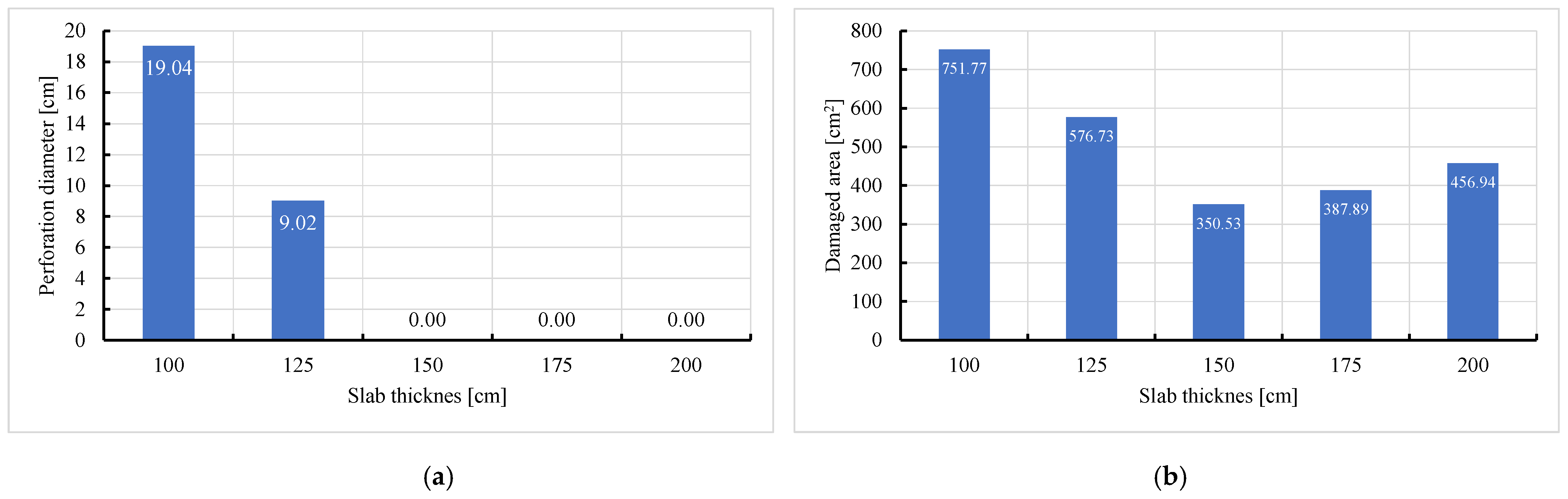
- Slab thickness: increasing the slab thickness reduced the perforation diameter drastically and transitioned damage from complete perforation to surface-level damage.
- -
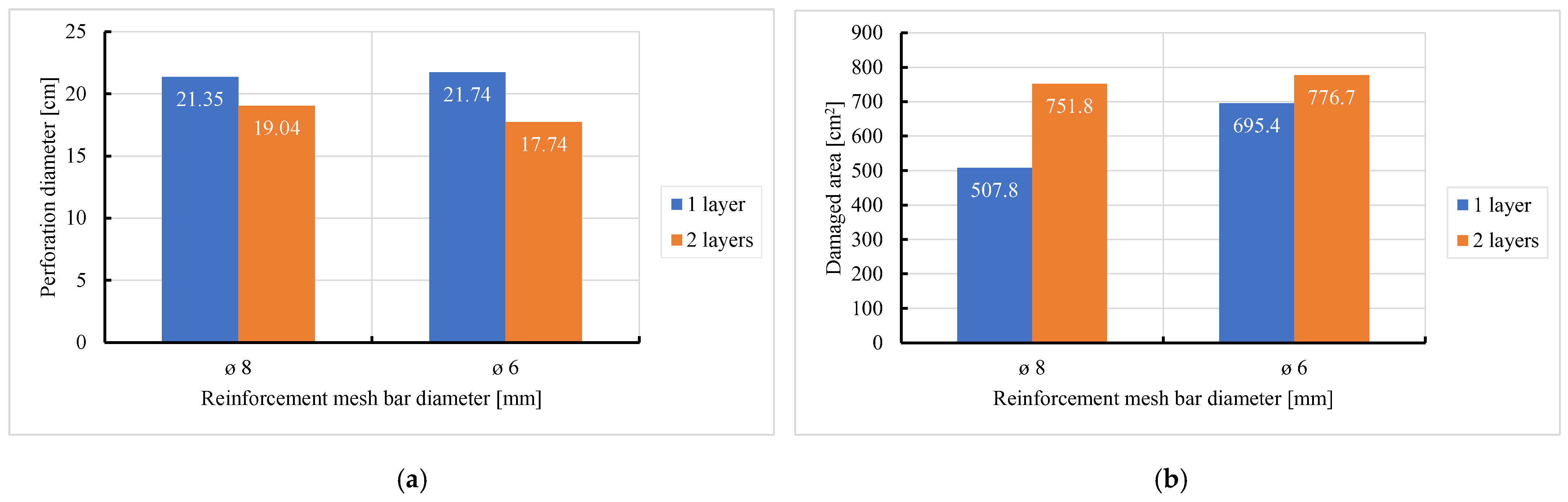
- Reinforcement area: higher reinforcement ratios (two layers of 8 mm bars) improved blast resistance by reducing perforation but increased the overall damaged area due to greater structural rigidity.
- Practical Implications
- -
- The findings emphasise the critical role of reinforcement design and slab thickness in enhancing blast resistance.
- -
- The validated numerical model offers a cost-effective tool for predicting damage and optimising the design of RC structures for blast mitigation.
Author Contributions
Funding
Data Availability Statement
Acknowledgments
Conflicts of Interest
References
- Ohtsu, M.; Uddin, F.A.K.M.; Tong, W.; Murakami, K. Dynamics of spall failure in fiber reinforced concrete due to blasting. Constr. Build. Mater. 2007, 21, 511–518. [Google Scholar] [CrossRef]
- Ohkubo, K.; Beppu, M.; Ohno, T.; Satoh, K. Experimental study on the effectiveness of fiber sheet reinforcement on the explosive-resistant performance of concrete plates. Int. J. Impact Eng. 2008, 35, 1702–1708. [Google Scholar] [CrossRef]
- Beppu, M.; Ohno, T.; Ohkubo, K.; Li, B.; Satoh, K. Contact Explosion Resistance of Concrete Plates Externally Strengthened with FRP Laminates. Int. J. Prot. Struct. 2010, 1, 257–270. [Google Scholar] [CrossRef]
- Yamaguchi, M.; Murakami, K.; Takeda, K.; Mitsui, Y. Blast Resistance of Double-Layered Reinforced Concrete Slabs Composed of Precast Thin Plates. J. Adv. Concr. Technol. 2011, 9, 177–191. [Google Scholar] [CrossRef]
- Gao, Z.; Chen, Y.; Wang, Z.; Li, S.; Wei, W.; Huang, C. Study on the failure effect of aramid reinforced concrete slab under localized blast loading. Structures 2024, 63, 106292. [Google Scholar] [CrossRef]
- Wei, J.; Liu, C.; Liu, J.; Yu, X.; Xu, S.; Su, Y. Investigations on geopolymer-based seawater sea-sand high performance concrete slabs reinforced with basalt FRP bars under direct contact explosions. Constr. Build. Mater. 2024, 411, 134538. [Google Scholar] [CrossRef]
- Shi, S.; Liao, Y.; Peng, X.; Liang, C.; Sun, J. Behavior of polyurea-woven glass fiber mesh composite reinforced RC slabs under contact explosion. Int. J. Impact Eng. 2019, 132, 103335. [Google Scholar] [CrossRef]
- Guo, S.; Liu, F.; Chen, J.; Yang, J.; He, X. Dynamic response and blast resistance mechanism of polyurea coating on RC slab during contact explosions. Constr. Build. Mater. 2024, 411, 134271. [Google Scholar] [CrossRef]
- Wang, W.; Huo, Q.; Yang, J.-C.; Wang, J.-H.; Wang, X.; Gao, W.-L. Damage analysis of POZD coated square reinforced concrete slab under contact blast. Def. Technol. 2022, 18, 1715–1726. [Google Scholar] [CrossRef]
- Wang, W.; Wei, G.; Yang, J.; Liu, F.; Gao, W. Study on antiexplosion performance of reinforced concrete slabs strengthened with POZD coated steel plate under contact explosion. Eng. Fail. Anal. 2022, 140, 106589. [Google Scholar] [CrossRef]
- Wang, W.; Wei, G.; Wang, X.; Yang, J. Structural damage assessment of RC slab strengthened with POZD coated steel plate under contact explosion. Structures 2023, 48, 31–39. [Google Scholar] [CrossRef]
- Li, J.; Wu, C.; Hao, H. Investigation of ultra-high performance concrete slab and normal strength concrete slab under contact explosion. Eng. Struct. 2015, 102, 395–408. [Google Scholar] [CrossRef]
- Li, J.; Wu, C.; Hao, H. Spallation of reinforced concrete slabs under contact explosion. In Proceedings of the 2016 Second Asian Conference on Defence Technology (ACDT), Chiang Mai, Thailand, 21–23 January 2016; pp. 42–45. [Google Scholar]
- Li, J.; Wu, C.; Hao, H.; Wang, Z.; Su, Y. Experimental investigation of ultra-high performance concrete slabs under contact explosions. Int. J. Impact Eng. 2016, 93, 62–75. [Google Scholar] [CrossRef]
- Ma, G.; Bai, G.; Wang, L.; Wang, F. Explosion resistance of 3D printing ultra-high performance concrete based on contact explosion tests. Int. J. Impact Eng. 2022, 169, 104316. [Google Scholar] [CrossRef]
- Luccioni, B.; Isla, F.; Codina, R.; Ambrosini, D.; Zerbino, R.; Giaccio, G.; Torrijos, M.C. Effect of steel fibers on static and blast response of high strength concrete. Int. J. Impact Eng. 2017, 107, 23–37. [Google Scholar] [CrossRef]
- Luccioni, B.; Isla, F.; Codina, R.; Ambrosini, D.; Zerbino, R.; Giaccio, G.; Torrijos, M.C. Experimental and numerical analysis of blast response of High Strength Fiber Reinforced Concrete slabs. Eng. Struct. 2018, 175, 113–122. [Google Scholar] [CrossRef]
- Zhao, X.; Wang, G.; Lu, W.; Yan, P.; Chen, M.; Zhou, C. Damage features of RC slabs subjected to air and underwater contact explosions. Ocean Eng. 2018, 147, 531–545. [Google Scholar] [CrossRef]
- Yang, G.; Wang, G.; Lu, W.; Wu, L.; Yan, P.; Chen, M. Experimental and numerical study of damage characteristics of RC slabs subjected to air and underwater contact explosions. Mar. Struct. 2019, 66, 242–257. [Google Scholar] [CrossRef]
- Zhao, X.; Wang, G.; Lu, W.; Yang, G.; Chen, M.; Yan, P. Experimental investigation of RC slabs under air and underwater contact explosions. Eur. J. Environ. Civ. Eng. 2021, 25, 190–204. [Google Scholar] [CrossRef]
- Dua, A.; Braimah, A. Assessment of Reinforced Concrete Slab Response to Contact Explosion Effects. J. Perform. Constr. Facil. 2020, 34, 04020061. [Google Scholar] [CrossRef]
- Cai, R.; Li, Y.; Zhang, C.; Cao, H.; Qi, H.; Mao, J. Size effect on reinforced concrete slabs under direct contact explosion. Eng. Struct. 2022, 252, 113656. [Google Scholar] [CrossRef]
- Yue, S.; Qiu, Y.; Zhang, N.; Wang, M. Analytical study of local damage on concrete slab subjected to a contact explosion. J. Vibroeng. 2017, 19, 908–929. [Google Scholar] [CrossRef]
- Luccioni, B.M.; Aráoz, G.F.; Labanda, N.A. Defining Erosion Limit for Concrete. Int. J. Prot. Struct. 2013, 4, 315–340. [Google Scholar] [CrossRef]
- Wang, Z.; Chen, W.; Hao, H.; Dong, Y.; Huang, Z. Numerical prediction of blast fragmentation of reinforced concrete slab using ALE-FEM-SPH coupling method. Finite Elem. Anal. Des. 2023, 220, 103948. [Google Scholar] [CrossRef]
- Wang, Z.; Chen, W.; Huang, Z.; Hao, H. Numerical study on perforation damage and fragmentation of reinforced concrete slab under close-in explosion. Eng. Fail. Anal. 2024, 158, 107985. [Google Scholar] [CrossRef]
- ANSYS. Ansys Engineering Analysis System User’s Manual; ANSYS Inc.: Canonsburg, PA, USA, 2019. [Google Scholar]
- Draganić, H.; Gazić, G.; Lukić, S.; Jeleč, M. Experimental investigation on blast load resistance of reinforced concrete slabs retrofitted with epoxy resin impregnated glass fiber textiles. Compos. Struct. 2021, 274, 114349. [Google Scholar] [CrossRef]
- Riedel, W.; Thoma, K.; Hiermaier, S. Penetration of reinforced concrete by BETA-B-500 numerical analysis using a new macroscopic concrete model for hydrocodes. In Proceedings of the 9th ISIEMS, Berlin, Germany, 3–4 May 1999; pp. 315–322. [Google Scholar]
- Johnson, G.; Cook, W. Selected hugoniots: EOS. In Proceedings of the 7th International Symposium on Ballistics, The Hague, The Netherlands, 19–21 April 1983. [Google Scholar]
- Jeleč, M.; Draganić, H.; Gazić, G.; Lukić, S. Post-blast residual static capacity of retrofitted reinforced concrete slabs. Eng. Struct. 2023, 286, 116161. [Google Scholar] [CrossRef]


| Parameters | B | M | D1 | D2 | εf, min | Erosion | A1 [kPa] | G [kPa] | fc [kPa] | Tensile Failure |
|---|---|---|---|---|---|---|---|---|---|---|
| RHT [29] | 1.60 | 0.6 | 0.04 | 1 | 0.01 | Geometric strain—1.5 Instantaneous/ Plastic strain/ Timestep/ Failure | 3.53 × 10⁷ | 1.67 × 10⁷ | 35,000 | Hydro/ Principal Stress/ User failure |
| Yang et al. [19] | + | + | + | + | + | Geometric strain—0.5 Instantaneous | + | 1.70 × 10⁷ | 38,000 | Hydro |
| Parameters | B | M | D1 | D2 | εf, min | Erosion | A1 [kPa] | G [kPa] | fc [kPa] | Tensile Failure |
|---|---|---|---|---|---|---|---|---|---|---|
| RHT [29] | 1.60 | 0.6 | 0.04 | 1 | 0.01 | Geometric strain—1.5 Instantaneous/Plastic strain/Timestep/Failure | 3.53 × 10⁷ | 1.67 × 10⁷ | 35,000 | Hydro/Principal Stress/User failure |
| Draganic et al. [28] | + | + | + | + | + | Geometric strain—0.375 Instantaneous | + | 1.70 × 10⁷ | 25,570 | Hydro |
| Geometric Strain | Perforation Diameter [cm] | Damaged Area [cm2] | ||||
|---|---|---|---|---|---|---|
| Simulation | Experiment | Relative Difference | Simulation | Experiment | Relative Difference | |
| 0.250 | 40.75 | 18.83 | 116.41% | 3335.04 | 790.65 | 321.81% |
| 0.275 | 27.88 | 18.83 | 48.06% | 3126.15 | 790.65 | 295.39% |
| 0.300 | 24.99 | 18.83 | 32.71% | 2269.11 | 790.65 | 186.99% |
| 0.350 | 24.49 | 18.83 | 30.06% | 2238.08 | 790.65 | 183.07% |
| 0.375 | 19.04 | 18.83 | 1.12% | 751.77 | 790.65 | 4.92% |
| 0.400 | 13.05 | 18.83 | 30.70% | 717.78 | 790.65 | 9.22% |
| 0.500 | 10.91 | 18.83 | 42.06% | 702.92 | 790.65 | 11.10% |
| 0.600 | 10.18 | 18.83 | 45.94% | 700.12 | 790.65 | 11.45% |
| 0.750 | 9.87 | 18.83 | 47.58% | 658.34 | 790.65 | 16.73% |
| Top Surface | Bottom Surface | |
|---|---|---|
| IGS |  | |
| 0.25 |  | 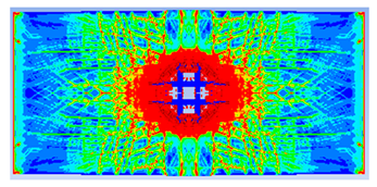 |
| 0.275 | 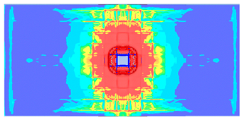 | 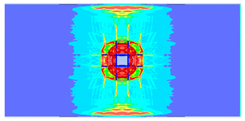 |
| 0.30 | 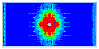 |  |
| 0.35 |  | 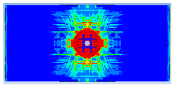 |
| 0.375 | 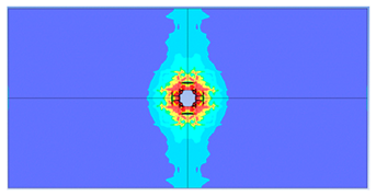 | 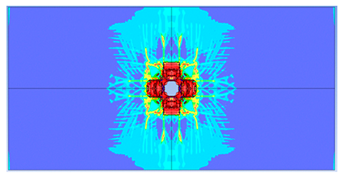 |
| 0.4 | 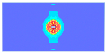 | 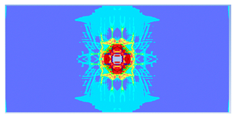 |
| 0.50 | 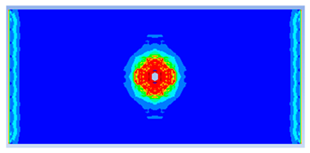 | 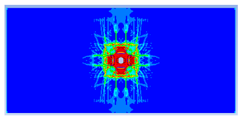 |
| 0.6 | 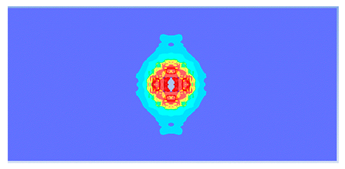 | 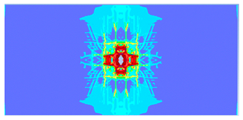 |
| 0.75 | 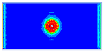 | 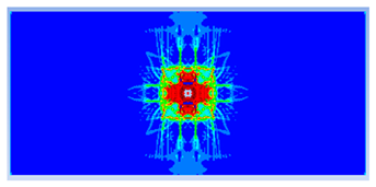 |
| Slab Thickness [mm] | Top Surface | Bottom Surface |
|---|---|---|
 | ||
| 100 | 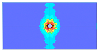 | 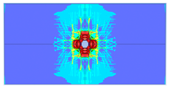 |
| 125 | 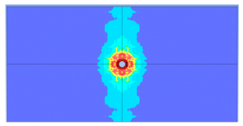 | 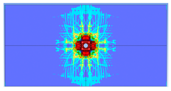 |
| 150 | 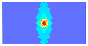 | 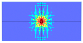 |
| 175 | 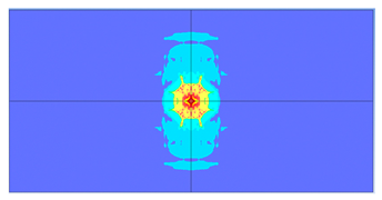 | 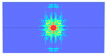 |
| 200 | 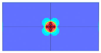 | 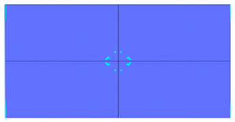 |
| Top Surface | Bottom Surface | |
|---|---|---|
 | ||
| 2 layers ø8 |  | 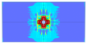 |
| 1 layer ø8 | 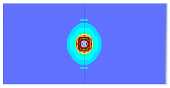 |  |
| 2 layers ø6 |  | 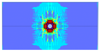 |
| 1 layer ø6 | 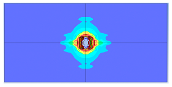 | 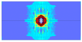 |
Disclaimer/Publisher’s Note: The statements, opinions and data contained in all publications are solely those of the individual author(s) and contributor(s) and not of MDPI and/or the editor(s). MDPI and/or the editor(s) disclaim responsibility for any injury to people or property resulting from any ideas, methods, instructions or products referred to in the content. |
© 2025 by the authors. Licensee MDPI, Basel, Switzerland. This article is an open access article distributed under the terms and conditions of the Creative Commons Attribution (CC BY) license (https://creativecommons.org/licenses/by/4.0/).
Share and Cite
Draganić, H.; Jeleč, M.; Gazić, G.; Lukić, S. Numerical Investigations of Reinforced Concrete Slabs Subjected to Contact Explosions. Buildings 2025, 15, 1063. https://doi.org/10.3390/buildings15071063
Draganić H, Jeleč M, Gazić G, Lukić S. Numerical Investigations of Reinforced Concrete Slabs Subjected to Contact Explosions. Buildings. 2025; 15(7):1063. https://doi.org/10.3390/buildings15071063
Chicago/Turabian StyleDraganić, Hrvoje, Mario Jeleč, Goran Gazić, and Sanja Lukić. 2025. "Numerical Investigations of Reinforced Concrete Slabs Subjected to Contact Explosions" Buildings 15, no. 7: 1063. https://doi.org/10.3390/buildings15071063
APA StyleDraganić, H., Jeleč, M., Gazić, G., & Lukić, S. (2025). Numerical Investigations of Reinforced Concrete Slabs Subjected to Contact Explosions. Buildings, 15(7), 1063. https://doi.org/10.3390/buildings15071063