1. Introduction
The use of building information modeling (BIM) allows building data to be stored in a structured way and to be shared in a digital, computer-interpretable form. An important question in the use of BIM is what information should be included in a BIM model. To ensure that the correct, necessary data are included, they must first be defined and should be linked to a real purpose. The relatively new ISO 7817-1 standard level of information need (LOIN) [
1] addresses this issue. This ISO standard took over and replaced the European EN 17412 [
2] standard. The LOIN specifies that information in BIM models should be linked to a specific need. The formulation of information requirements for these needs, designated as use cases, is of significant current interest. In recent years, the challenge of how to define information requirements and provide them in a computer-interpretable way was tackled in [
3,
4,
5,
6,
7,
8,
9]. With the publication of the new buildingSMART International (bSI) standard on the information delivery specification (IDS) [
10], a common standard seems to be emerging. The IDS is an XML-based schema for defining alphanumeric information requirements for BIM models, represented in the open ISO 16739-1 standard on industry foundation classes (IFC) [
11]. Geometry definitions are not within the scope of the IDS. The IDS is intended to be imported into BIM authoring and checking software for configuration. Until now, configuration has been a manual step or limited to native formats [
12]. Tomczak et al. [
6] compared different options and formats for defining information requirements in 2022 and identified the IDS as the most beneficial method. The IDS is already well established in BIM processes in the construction industry and in BIM research. Several organizations and research projects have recently defined information requirements and are using the IDS to provide them in an interoperable way [
13,
14,
15,
16,
17,
18,
19,
20,
21]. The purpose of these initiatives is to map information requirements to the IFC schema and store them in the IDS. However, research on the IDS is not limited to mapping the information requirements of different use cases but also explores its suitability for other purposes, such as code compliance checking [
22] and possible extensions [
23,
24] to the schema. This highlights the potential role that the IDS can play in BIM processes.
In the current version 1.0, the IDS can represent various IFC-based alphanumeric information, including IFC entities and PredefinedTypes, entity attributes, properties, quantities, external classifications, materials, and relationships. These types of information are handled by different IDS facet parameters. For example, the entity facet handles entity names and PredefinedTypes based on ISO 16739-1 [
11], while the property facet handles properties and quantities. An essential functionality of the IDS is that these facet parameters can be used to specify the required information, as well as the elements that require the information. This allows alphanumeric information requirements to be not only defined very specifically but also applied to very specific elements. Overall, an IDS file contains a list of all specifications to represent the total alphanumeric information requirements in a hierarchical structure. Each specification contains two parts, the applicability and the requirements, both of which consist of the facet parameters that define the actual content. This is in contrast to classical information requirements, which are usually defined in tabular form, for example, in [
13,
15,
20,
25,
26]. Whether the definition is carried out in a spreadsheet or a BIM data structure tool such as BIMQ [
27], the structure is usually tabular and simple. The tabular structure typically contains entity-based property definitions. The different columns define the types of information, e.g., a column for entity names, a column for property names, and a column for property values, and different rows define different requirements. IDS files are created from this tabular structure. However, these information requirements do not exploit the full potential of the IDS. Apart from entities and properties, hardly any other functionality is used.
There are existing tools that can convert information from a tabular structure to the IDS, allowing the full functionality of the IDS to be used [
28,
29]. However, their tabular structure is significantly different from classic information requirement tables. Tomczak [
28] introduced a matrix that defines different applicabilities in the columns and the requirements in the rows. Selecting individual cells within the matrix defines which requirement is associated with which applicability. Dias [
29] used columns to define different types of information and rows to define different requirements, but to organize this information into applicability and requirements, it was separated into different individual tables. Both methods are more in line with the structure of the IDS schema than the current method used in information requirement tables.
The shortcomings of existing solutions hinder the use of the IDS with its full functionality in practice. Practitioners and researchers have information requirements in the form of entity-based property lists. These existing classical entity-based property lists do not exploit the full functionality of the IDS, and existing IDS tools, whether in tabular or hierarchical form, differ significantly from the classical structure. As a result, transforming existing information requirements into these systems requires significant manual effort. For this reason, the step from entity-based property lists to detailed IDS definitions is often not realized in practice. This step would allow information requirements to be transformed from simply requesting and verifying the existence of information to requesting and verifying logical information, which could increase the quality of BIM models. Therefore, the aim of this research is to identify the possibilities of representing more IDS functionality in a similar tabular structure in order to bridge the gap between classical information requirements and the IDS. The approach taken in this research is to start with the classical structure and extend it to support the full functionality of the IDS while still allowing the use of the established structure. Since clients, building authorities, and planners have been working with tabular structures for years and have experienced employees in this area, this approach should enable a smooth transition. This promotes the acceptance and dissemination of the IDS, even among stakeholders who have had little contact with information requirements in the BIM context so far.
Section 2 describes the materials and methods for extending classical information requirement tables.
Section 3 applies the new structure to the existing information requirements of two Austrian case studies to demonstrate the applicability of the approach. Finally,
Section 4 discusses the results in relation to the current state of the art and describes the advantages, potential, and limitations of the proposed approach.
2. Materials and Methods
The development of the new structure is strongly based on the current way of defining information requirements for IFC models. Therefore, the development starts with the analysis of a classical information requirement structure and its mapping to the IDS schema. In the following steps, the IDS functionalities that have not yet been considered are included step by step by extending the classical structure. Finally, the concept is implemented in a software prototype to validate its functionality.
2.1. Comparison of Classical Information Requirements and the IDS
The computer-interpretable information requirements for BIM models typically relate to the alphanumeric characteristics of elements, known as the level of information (LOI). According to the international LOIN standard ISO-7817-1 [
1], this alphanumeric information consists of the identification and the information content of elements. Typically, in IFC models, the identification is defined by classes of elements called IFC entities, and the information content includes required properties.
The definition of a required property includes its name, the name of the property set in which it is included, its data type, and, optionally, the constraint of the property values. Properties are assigned to IFC entities. This entity-based approach means that each element of the entity must have all of the defined properties. In addition to entities, PredefinedTypes are often used in IFC to make more specific distinctions between classes of elements. For example, for the IfcWall entity, PredefinedTypes distinguish between solid walls, movable walls, parapets, etc. This information can be easily represented in a tabular structure.
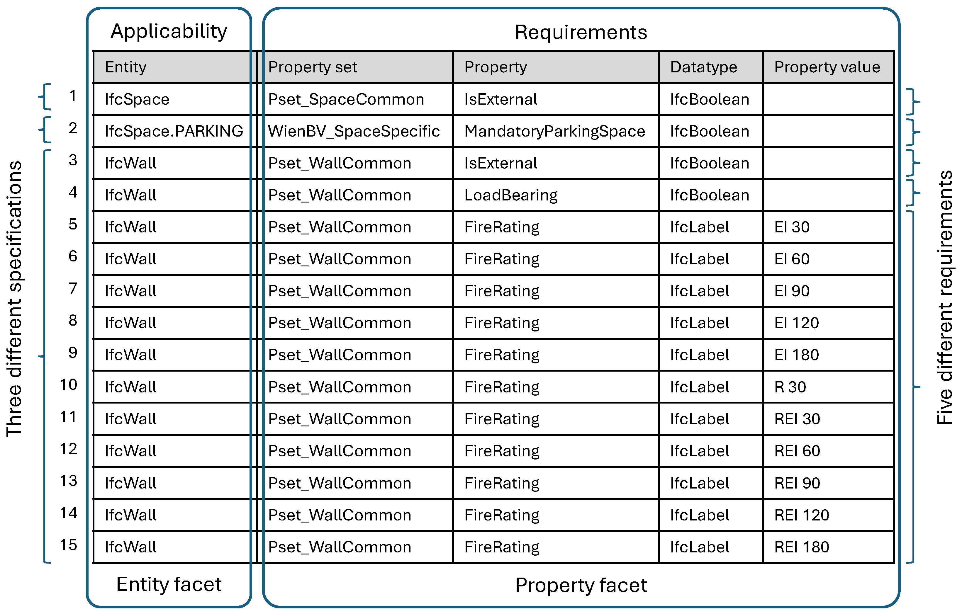
Figure 1 shows an example consisting of two different entities (IfcSpace and IfcWall), a PredefinedType (PARKING), three standard IFC properties (IsExternal, LoadBearing, and FireRating), and a custom property (MandatoryParkingSpace). The different columns define the types of information, and the different rows define the different requirements. Five columns are required to define entity-based property lists. The first column contains the IFC entity and the PredefinedType (see
Figure 1, row 2). In Austria, it is common to combine this information into one value and separate it with a period (Entity.PredefinedType). This is followed by four columns for the property definition: property set, property, data type, and property value.
The information is already well structured for representation in the IDS. The different columns and rows represent a structure that is also found in the IDS. The entity column defines which elements are affected by the specification. Therefore, it defines the applicability section of the IDS. In addition, the entity column contains the name of the entity and the PredefinedType, which corresponds to the information represented by the IDS entity facet. For conversion in the IDS, it is only necessary to separate the two values and assign them to the two IDS parameters of the entity facet. The other four columns define property information required for the specified elements and, therefore, correspond to the requirement section of the IDS. Each of these columns can be assigned directly to the property facet. While the columns distinguish between different types of information used in applicability and requirements, the different rows allow multiple specifications, requirements, and values to be defined. A difference between two rows has a different meaning depending on the column. In the applicability columns, different information in rows means that a different entity or PredefinedType is involved, so there is no relationship between these rows (see
Figure 1, rows one, two, and three). Therefore, in the IDS, different rows represent different specifications. In requirement columns, different rows can typically have two meanings. Firstly, a different property is required. For example, in
Figure 1, rows three and four define two different required properties. However, the applicability is the same. So, the same entity requires both properties. In the IDS, this case is represented by multiple property facets within the requirement section of a specification. Secondly, a difference in the property value column defines different possible values if the other columns are not different. This can be used to define a list of possible values, such as the fire rating of a wall (see rows five to fifteen in
Figure 1). Overall, five different property requirements are defined in
Figure 1. While the first four rows each define individual requirements, rows five to fifteen all concern one requirement. Since requirements three to five have the same applicability, they are incorporated into one specification, making it three specifications in the example. In summary, a difference between rows can indicate different specifications (“and” logic), different requirements within a specification (“and” logic), and different possible property values (“or” logic).
This analysis of the classical information requirement definitions in a tabular structure shows that the information can be easily mapped to the IDS schema. However, the IDS schema provides more functionality. The table uses the entity facet in the applicability and the property facet in the requirements, as well as list values. There are four other facets available in the IDS for specifying information requirements. These are the attribute facet for attributes, the classification facet for external classifications (in addition to IFC entities), the material facet for material names, and the partOf facet for relationships between elements. All of these can be used in the applicability and requirements, allowing very specific information requirements to be defined. The IDS also allows values to be restricted by pattern, length, and bounds (for numerical values). However, these functionalities are not yet widely used. To facilitate their use, the next steps will be to extend the structure of existing entity-based information requirement tables to advanced IDS definition tables.
2.2. Extension to All IDS Facets
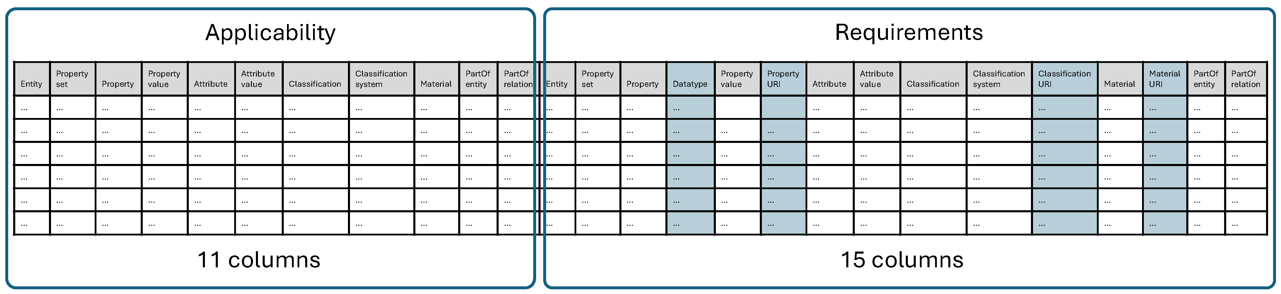
The first extension to an advanced IDS definition table is to allow the definition of all existing IDS facets. This step is about what information can be defined. The IDS facets have different parameters to define information. For the entity and property facets, these parameters are represented in the classical tabular structure by different columns (except for entity and PredefinedType, which are combined in one column). This logic contained in the existing structure can be generalized to represent the parameters of any IDS facet. For each additional parameter in an IDS facet, a new column is created. For the attribute facet, this concerns the parameters for the attribute name and value. For the classification facet, columns are required for the classification system, the classification name, and the URI (uniform resource identifier). The URI parameter also applies to the property facet. The material facet requires a column for the name of the specified material and one for the URI. Finally, the partOf facet contains parameters for the relationship between two elements and the associated entity name. In total, there are 16 parameters for all facets.
The IDS is designed to define the applicability and requirements of a specification in a very similar way. Both use the same facets to define information. Therefore, it is necessary to allow the definition of the facet parameters for the applicability and the requirements. This can be achieved by introducing two blocks in the tabular structure, both of which contain the columns for the IDS parameters. This means that each column is contained twice, once for the applicability and once for the requirements. This is necessary because the same facet can be used in both parts of a specification. Exceptions to this are the columns for the URI, which can only be included in the requirements as defined in the IDS schema definition. In addition, the data type column for the property facet can also be omitted in the applicability block. The data type is an optional parameter and is constant for a given property. When the property is defined in the requirements of another definition, its data type is already defined. The combination of the property set, property name, and property value uniquely defines a property facet. Therefore, the data type is not required for applicability, which reduces the number of columns. This results in a required number of 11 columns in the applicability block and 15 columns in the requirements block (one less than the number of facet parameters, as the entity and PredefinedType are combined) to define all IDS facets in a tabular structure, giving a total of 26 columns (see
Figure 2).
This extension shows that the hierarchical structure of the IDS schema, consisting of specifications with applicability and requirements, both consisting of facets, can be represented in a simple tabular structure. This requires more than five times the number of columns than the original information requirement’s definition. However, this is only true if all parameters are actually used within an IDS, which is unlikely. Therefore, we propose an approach where columns are optional. Columns that are not required can be omitted. This covers information requirements from very simple ones, where only entity-based properties are defined, to the use of all IDS facets.
2.3. Extension to Complex Restrictions
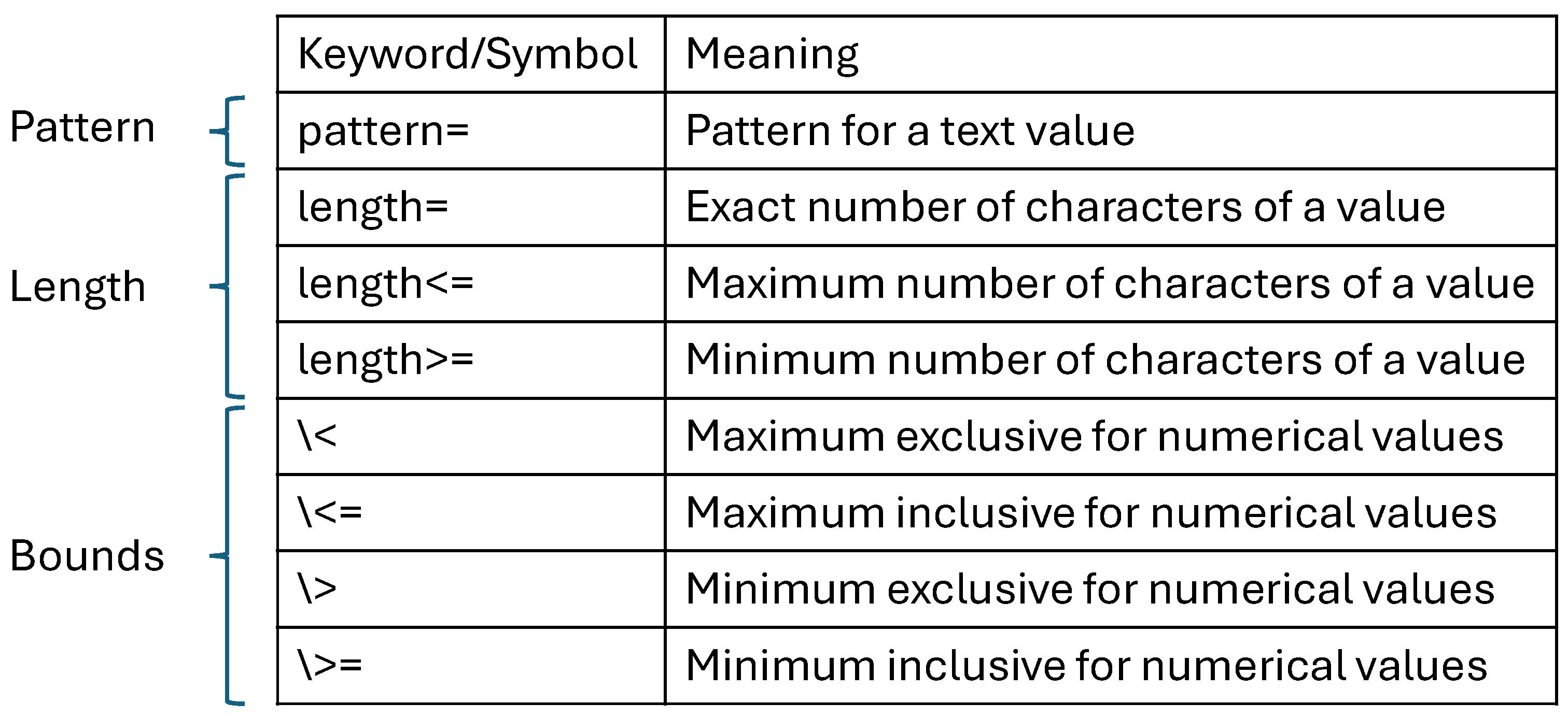
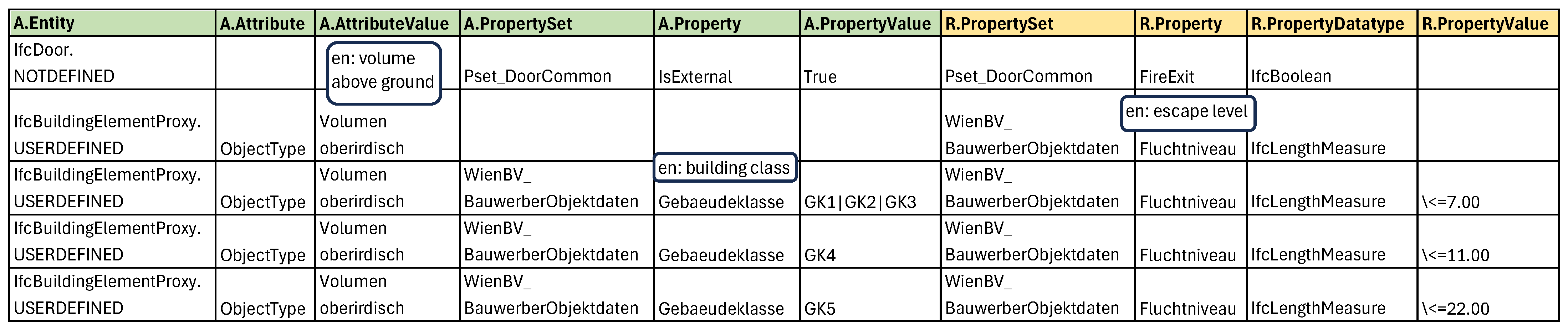
The next step toward an advanced IDS definition table is to enable the ways in which information can be defined. The IDS can define information as simple values and four complex restrictions, which are enumerations of values, patterns, lengths (number of characters of a value), and bounds on numerical values. In the example in
Figure 1, the facet parameters are defined as simple values and an enumeration of possible values. In both cases, a cell contains a single value because the enumerated values have been split into several rows. To enable the additional value options, keywords and symbols can be defined. These keywords and symbols indicate that a complex restriction is defined in a cell instead of a simple value. The value contained in a cell is separated into the keyword or symbol that defines the type of complex restriction and the actual value stored in the complex restriction.
Figure 3 shows the different proposed keywords and symbols for the complex restrictions pattern, length, and bounds.
The fourth complex restriction, enumeration, is already included in the initial table structure but has limitations. Different rows are used for an enumeration of possible values only in the property value column of the requirement part. This is a special case. In all requirement columns, the rows represent an “and” logic for individual facets. In the applicability columns, a difference in the rows represents an “and” logic for specifications. In order to allow enumerations in columns other than the property value column of the requirements part, it is necessary to include all enumerated values in one cell. This can be achieved by introducing another key symbol or delimiter to separate the individual values. In this research, the “|” symbol is used as a delimiter for “or” values. A difference from the other key symbols is that this symbol is not placed at the beginning of a value to indicate a complex restriction. Instead, it is only used to separate the values. This not only allows enumerations to be used to define all facet parameters but also significantly reduces the number of requirement rows.
In the requirement part, this “or” logic has a clear purpose of defining enumerations of possible values. However, in the applicability part, it can also serve a different purpose: the assignment of generally applicable requirements. The aim of the applicability part of the IDS is to define information requirements specifically for the elements that require them and to avoid including the information in unnecessary elements. Historically, before the use of the IDS, information requirements were defined on an entity basis, as shown in
Figure 1. This approach often resulted in a property not being required for all elements of the entity. However, omitting the property for these elements would cause an error in formal model checking, as the information requirements define that all elements of the entity require the property. For this reason, general values have been introduced to indicate that the information is not required for a particular element. In Austria, the use of “ND” for “not defined” and “NE” for “not required” is common. In this way, formal model checks can be applied, as all elements contain the property and a value. The handling of these general values is challenging when, for example, required values for a property are defined in dependence on another property, as is possible for fire rating values in dependence on load-bearing values. While the values beginning with “R” apply only to structural elements, and the other values apply only to non-structural elements, the general values “ND” and “NE” apply to both. In an IDS file, it is necessary that these values appear in both specifications; otherwise, a formal model check would not work properly. There are two ways to achieve this in the tabular structure. Firstly, the values could be included in both rows, defining the different possible values. However, this is a change from the classic information definition table, where all possible values of a property are only included once per specification. A second approach is to use the “or” delimiter in the applicability to define a general applicability for these general values. Such a row does not represent a single specification but defines the more specific specifications to which the general values must be added.
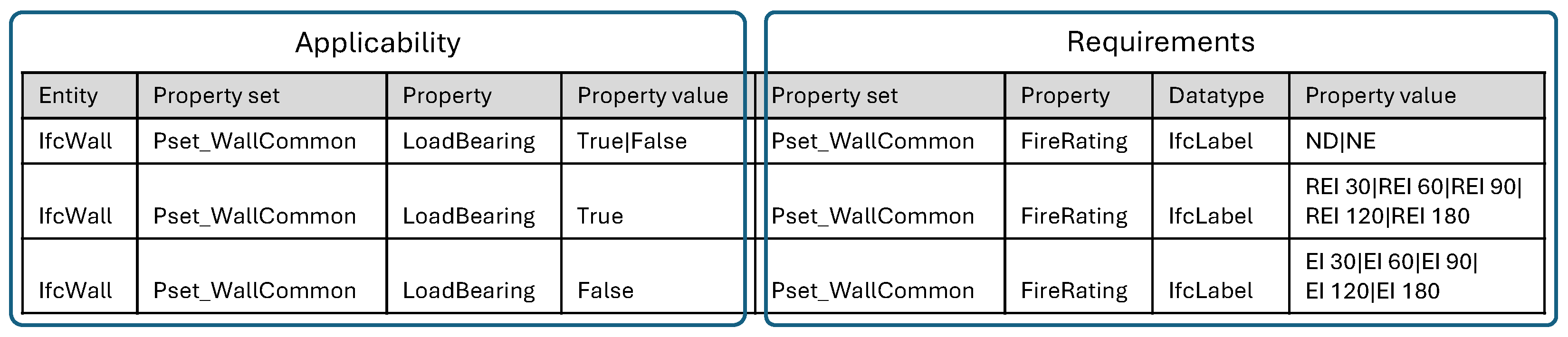
Figure 4 shows the example of fire rating values of a wall depending on the load-bearing property. The first row defines the general values. The second and third rows define the values for load-bearing and non-load-bearing walls. These three different rows correspond to two different specifications in the IDS because the tabular structure defines only two different applicabilities: load-bearing and non-load-bearing. The first row contains both. On the one hand, this approach allows generally applicable values to be clearly defined. On the other hand, it is no longer possible to define enumeration restrictions in facets of the applicability part, as the values are always broken down into individual specifications. In this research, it was decided to use the “or” values in the applicability for general values, as these occur more frequently in current information requirements. With the ability of the IDS to define information requirements for specific applicable elements, general values such as “ND” and “NE” should no longer be necessary in the future. The functionality of the “or” delimiter in the applicability could then be changed to create enumeration restrictions as in the requirements part.
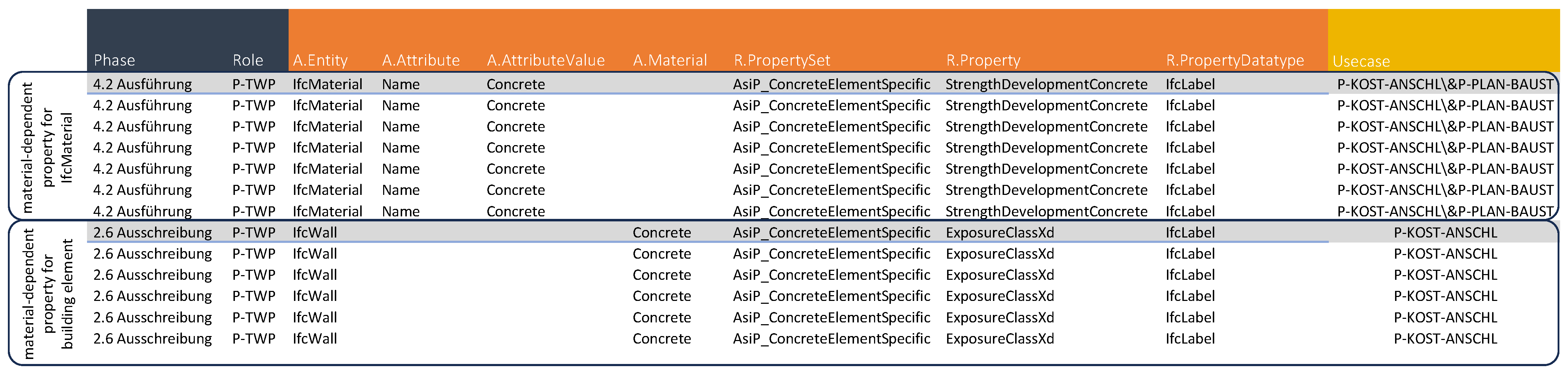
The given logic of the different rows requires another key symbol. A specification can contain the same facet with different content several times. This requires an “and” logic between the facets. While the different information in the rows of the requirement part follows this logic, different rows in the applicability part indicate different specifications. Therefore, to allow multiple facets within the applicability of a specification, the facets need to be combined into one row. This can be achieved by using the “\&” symbol to define an “and” logic within a cell. If the applicability uses the same facet twice with different definitions, then multiple values can be included in each column of the facet, separated by the delimiter.
Figure 5 shows the applicability definition of a wall that is load-bearing and not external in the tabular structure and in the IDS. In this example, for each of the columns of a facet, the property facet must have the same number of “and” values within a cell (see
Figure 5a). From each cell, the values at the same position between the delimiters are retrieved and included in the same facet in the IDS. For the example of a wall that is load-bearing and not external, two individual property facets are created in the applicability (see
Figure 5b), indicating an “and” logic.
2.4. Introducing General Information
Information requirements should always be defined for a clear purpose. This means that a particular actor needs information at a particular time in order to perform a particular action or use case. This corresponds to the questions of who, when, and why information is needed, which are part of the established information delivery manual (IDM) [
30] and level of information need (LOIN) [
1] standards for defining information requirements. In the IDS, information about the milestone (when) and the purpose (why) can be included in the metadata of the IDS file. This means that this information is defined for the whole file and is, therefore, the same for all specifications. The definition of responsible roles is not intended. However, the metadata of a specification can be used to include all three types of information at the specification level. The two metadata parameters, “description” and “instructions”, are suitable for carrying the information. This makes it possible to combine specifications with different actors, milestones, and purposes in one IDS file, e.g., to create a general IDS file for a project. Such a file can be useful for importing into BIM authoring software and automatically generating all of the necessary properties. In contrast, different files per milestone may be useful, for example, for formal model checking at different project stages. The definition of the general information of the actor, milestone, and purpose can be included in the definition table with an additional column for each of them. This allows a different mapping for each row in the table. In addition to storing this information in the metadata of the specifications, the specifications can also be grouped by this information. With this approach, the information definition table allows general (for the whole project) and specific (for a particular milestone, purpose, or actor) IDS files to be generated from the same dataset.
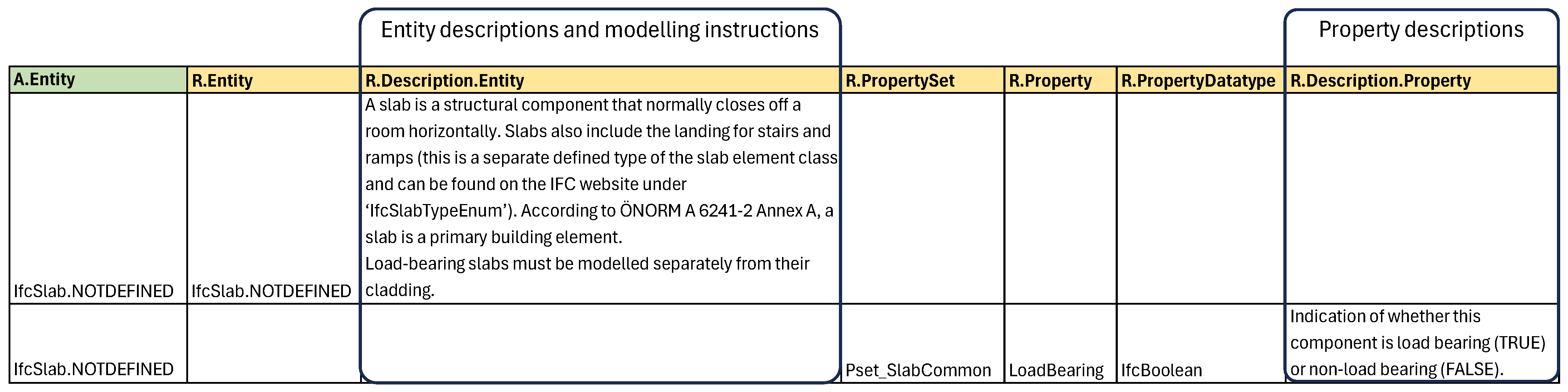
Other general information often included in information requirements is descriptions, such as descriptions of entities and properties. These descriptions are often provided in separate text files, which means that there are two different sources of information. By including this information in the tabular structure described above and, thus, into the IDS, all relevant content can be bundled into a single source. This could eliminate the need for additional documents, which increases the consistency and traceability of the requirements. A single, contract-ready document that provides clients, building authorities, and planners with a clear basis for communicating and reviewing requirements is created.
The description of an entity or property concerns the facet layer. For a facet, it is possible to include instructions as XML attributes, but only when the facet is used in the requirements part of an IDS. All properties typically appear somewhere in the requirements of a specification. Therefore, the description can be included there. In contrast, entities typically only appear in the applicability part of a specification. To allow the inclusion of entity descriptions, we propose adding the entity facet to the requirement part once per the applicable entity. This leads to the requirement that, for example, an IfcWall element (applicability) must be of the IfcWall entity (requirement). Although this requirement is trivial, it allows the description of the entity to be included in the IDS. A special case is that of user-defined PredefinedTypes. For two different user-defined types in an IFC, the entity and the PredefinedType are the same, but the object type attribute is different. Therefore, the description refers to the combination of the entity column and the attribute columns. The attribute columns are, therefore, additionally required in the requirements part of the IDS. The description can remain in the entity facet, but it must be considered together with the attribute facet when interpreting the description of an entity with a user-defined PredefinedType.
2.5. Software Prototype Implementation
The software prototype implementation aimed to provide a proof of concept for the proposed approach. The prototype was developed using the open-source IfcOpenShell library (version 0.7.11) [
31] for the Python programming language (version 3.12.4). IfcOpenShell provides a package called IfcTester for processing IDS files. IfcTester fully covers the functionality of the six IDS facets and allows the export of IDS files.
The software prototype was developed to process a single Microsoft Excel file containing two sheets. The first sheet contains general information about the IDS to be generated, such as the IDS metadata (title, version, author, etc.) and whether separate files should be created for each milestone (phase), purpose (use case), or actor (role). The second sheet contains the information requirement table. For this sheet, we implemented the optional use of columns approach. This keeps the number of columns small for simple information requirements such as entity-based property lists. Classical information requirements tables, such as the one in
Figure 1, can be processed directly. The additional columns are only needed for more complex requirements using all facet parameters. The prototype software application identifies the columns (facet parameters) by predefined column names. As the same facet parameters appear in both the applicability and the requirements, column names start with prefixes to distinguish between these two parts. Applicability column names start with “A”, and requirement column names start with “R”. Apart from this predefinition, the structure of the spreadsheet is flexible. The order of the columns is not predefined, and the sheet can also contain additional custom columns that are ignored by the prototype converter. This allows maximum flexibility for the user and adaptability of the structure to their typical information requirement structure. The software prototype minimizes the number of specifications in the final IDS file. It does this by combining rows with identical applicability into one specification. Finally, the specifications are exported to either one or more IDS files, depending on whether they are to be separated by phase, use case, or role.
4. Discussion
This study proposes a new tabular structure for defining alphanumeric information requirements that can be easily translated into the open standard IDS. The approach aims to bridge the gap between the full functionality of the IDS and the currently established ways of defining alphanumeric information requirements. The authors see this bridge as an enabler for the spread of the IDS throughout the BIM community, as it combines a common process with new technology. The concept was validated by applying the new structure to two existing information requirements defined in tabular form. The new structure was able to represent the original entity-based property lists of both considered data sources. Transferring the data to the new structure was easy in both cases. This can be attributed to the fact that the approach takes the current state-of-the-art, entity-based property lists as a starting point and extends it to consider more elaborate IDS functionalities. This is achieved by mapping the existing columns of these lists to the IDS schema and adding additional columns for the missing information (e.g., additional facet parameters). The logic of the table, with different types of information in different columns and different requirements in different rows, remains the same. This is a major advantage of the structure that we have developed. For complex information requirements that include all IDS facets, the new structure requires several new columns. This includes all of the currently considered columns, presenting results in a structure with 31 columns. While such a table may not possess the immediate comprehensibility of the original, solely entity-based property list, it significantly enhances functionality and retains the ability to be filtered to locate specific information.
A comprehensive overview table with filter options makes it easier to manage and process information requirements. Additionally, the table implements a flexible structure; all columns are optional and are identified by predefined names. This allows for a customizable arrangement of the columns and makes the complexity scalable since the number of columns can be flexibly selected. The structure allows one to start with a simple property assignment to an entity with a few columns and to gradually increase the information density. This ranges from five columns for classic entity-based property lists to an extended structure in the openBIM building permit (15 columns) and AIA4ALL (16 columns) case studies and to a maximum number of 31 columns for complex special cases. In addition, the flexible column arrangement facilitates the transfer of existing internal structures. To transfer a property-based list into the new system, it is usually sufficient to adjust the relevant column names. In the original Excel files of the case studies considered in this research, some additional adjustments were necessary. First, empty cells had to be filled. For example, in lists of possible values defined in different rows, as shown in
Figure 1, the property data type was only included in the first row. This value had to be included in all rows of the value list. Second, the use of user-defined PredefinedTypes required the columns for the attribute facet to be included, which made the list slightly larger than the original list. In the original list, the user-defined value was appended to the entity and PredefinedType in a cell. This had to be extracted and added to the attribute facet columns. This extra effort is due to the design intent to treat the object type attribute containing the user-defined type as a normal attribute. Due to its close association with the entity column, integration with the entity column would be possible, as implemented for the PredefinedType attribute. However, the combination of several different facet parameters in one cell hinders the filter functionality within the tabular structure. In addition to the attribute columns, the other additional facet columns allowed the refinement of the information requirements of the case studies. In particular, the use of the property and material columns in the applicability allowed requirements to be mapped more precisely and unnecessary information to be reduced. Therefore, the inclusion of attribute, property, and material parameters as applicability columns is the most important extension of the classical tabular structure for the considered use cases. This is followed by the key symbols for defining limits for numerical values and the ability to define general information, such as descriptions for properties and entities, as well as mapping to phases, roles, and use cases. Additional IDS functionalities, such as the classification and partOf facets and the additional complex constraints, were not required for the case studies. However, the authors strongly believe that a holistic consideration of all IDS functionalities is necessary to facilitate IDS adoption.
The new approach differs from existing tabular IDS definition concepts. The concepts of Tomczak [
28] and Dias [
29] also allow the use of multiple IDS facets within a tabular structure. However, they tried to solve the problem from the side of IDS functionality and did not focus on connecting it to the established entity-based property lists. Tomczak [
28] used a matrix structure with different applicabilities defined in the columns and different requirements in the rows. This increases the complexity of the table in both dimensions as the number of specifications grows. In our approach, the number of columns is limited by the number of facet parameters and the general data considered. The solution of Dias [
29] is closer to the established entity-based property lists, as it uses columns to represent the facet parameters and rows for different requirements. However, it separates the definition of specification metadata, applicability, and requirements into different sheets, making it harder to understand the relationship between the different parts of the IDS. Traceability is very important for an information requirement table, as it is intended to manage and edit the definitions, while the IDS then stores them independently. In addition, our new approach introduces two key symbols that enable functionality that was not previously considered. The “\&” symbol allows multiple occurrences of the same facet to be defined within the same row, combining them with an “and” logic. This functionality is necessary to combine multiple occurrences of the same facet in the applicability of a specification. While this is possible for requirements by using different rows, different rows in the applicability part of the table already represent different specifications. The “|” symbol allows multiple “or” values to be defined within a cell, allowing the applicability of general values to be defined. When values are assigned to elements in a more specific way than that based on entities, as is possible for the fire rating property of walls depending on their load-bearing property, in current practice, there are also general values that are relevant for all walls. In Austria, the values “NR” (not relevant) and “NE” (not required) are defined. Instead of duplicating these values in the requirements, the use of the “or” symbol in the applicability makes it possible to define a general applicability for them. The aim is that these general values will not be needed in the future when property requirements are already defined for specific elements. However, these values are included in current information requirements, and people are used to them. Ignoring current practices could hinder the implementation of the IDS. In contrast, the new tabular structure facilitates a gradual transition to a more specific definition of information requirements and usage of the IDS.
Another advantage of the new approach is the support of both intended uses of the IDS: the definition and verification of information requirements. This is done by separating the specifications into different files depending on the use case, phase, and responsible role (according to ISO 7817-1 [
1]). For defining and providing information requirements, IDS files per role or domain, as well as an overall IDS file, can be beneficial. This allows the relevant information to be provided to those who actually need it, and the IDS files can be imported into authoring software to automatically create the defined information structure. For checking information, IDS files per phase are beneficial as they represent the required quantity and quality of information for a specific milestone. Such IDS files can be used to configure checking software. In addition, the approach showed that the IDS can contain additional documentation that often accompanies alphanumeric information requirements. This can be descriptions of entities or properties, as well as the level of geometry per entity. In the new structure, this information can be defined in individual columns and stored in the IDS in the instructions. This extends the purpose of the IDS and allows the required information to be contained within one source. However, as the IDS only allows such descriptions at the facet level in the requirement part, the entity and property facets must be included in the requirement part. While the property facet is usually included anyway, the entity facet must also be added. This leads to a trivial requirement that an element of a particular entity must be of that particular entity, which makes the IDS file slightly larger.
The development and application of the new approach have demonstrated its ability to define information requirements to be used in the IDS format. However, this research has some limitations. The developed prototype includes all IDS facets and their mandatory parameters, but some IDS functionalities have not yet been considered. One of them is cardinality. Cardinality can be defined in the IDS for a specification (within the applicability type) and for all facets when used in the requirement part. By defining the cardinality of a specification, it is possible to restrict how often the applicable elements must occur in the model, from exclusion to unlimited occurrence. As this definition affects the whole specification, an additional column would cover this functionality. The definition of cardinality for the facets in the requirements is intended to define whether an applicable element must have, may have, or may not have the defined characteristic. As this can be individual for each facet, fully covering the functionality would require an additional column for each facet in the requirement part, making six more columns. An alternative would be to include only one additional column for all facets. Then, only one facet could be used per row; otherwise, it would not be clear which facet the cardinality column refers to. This saving of columns would lead to an increase in the number of rows in the table. In addition, the title of a specification is not yet definable but could be included in an additional column. However, this discussion shows that the missing information can easily be included by introducing additional columns. Whether they should all be included remains to be examined, but the way they can be included shows how suitable this tabular structure is for IDS definitions. In future work, the structure should be applied to more existing information requirements to further validate its functionality and find potential improvements. In addition, the structure could be used to extend the structure of existing data structure tools such as BIMQ, which already uses a tabular form, to allow for more sophisticated IDS coverage.


