1. Introduction
Negative stiffness structures exhibit the remarkable ability to create a localized vibration “sink”, effectively channeling vibrations into a specific absorber. This mechanism is analogous to the behavior of acoustic/elastic metamaterials (EMMs), which induce bandgap phenomena. Specifically, a bandgap functions as a frequency barrier within which wave propagation is inhibited, thereby facilitating the reduction of vibrations in the structure [
1,
2,
3,
4,
5].
Over the past two decades, elastic metamaterials (EMMs) have garnered considerable attention due to their distinctive effective material properties [
1]. These artificially engineered materials are capable of manipulating and directing the propagation of elastic waves through a localized resonance mechanism that interacts with acoustic/elastic waves. When the frequency of the propagating wave aligns with the localized resonance of the microstructure, the electromagnetic field can exhibit unique dynamic properties, properties like negative effective stiffness and negative effective mass density have been investigated for diverse purposes, encompassing seismic waveguide designs, acoustic absorption mechanisms, and methods for vibration mitigation [
6,
7,
8]. Negative stiffness originates from structural instability or nonlinear geometric deformation, manifested as the negative slope region of the force displacement curve, with the core function of low-frequency energy dissipation. Negative effective mass is achieved through local resonance units or quantum control to reverse the equivalent inertial force, manifested as acceleration direction opposite to external force direction. Typically, electromagnetic fields are constructed by incorporating periodic mechanical subunits into natural materials to induce localized resonance responses and modify wave characteristics such as velocity, direction, and wavelength. However, the geometric shapes of electromagnetic metamaterial (EMM) subunits are often limited, as these models are only applicable to wavelengths exceeding their overall dimensions. Current research primarily focuses on areas such as acoustic resonators [
9], subwavelength guiding [
10], ultrasonic focusing [
11], elastic wave absorption [
12], structural vibration reduction [
13], and seismic wave manipulation [
14].
Negative stiffness structures have emerged as promising alternatives to elastic metamaterials (EMMs) for mitigating vibrations caused by earthquake-induced elastic waves. In recent years, various designs and applications of these structures have been proposed. Nagarajaiah et al. have designed a negative stiffness device (NSD) [
15,
16,
17,
18] that incorporates pre-compressed springs and friction pendulum sliding components. Subsequent studies [
19,
20] have evaluated the effectiveness of these NSDs. Cheng and Shi [
21,
22,
23] have introduced seismic isolation foundations that exhibit distinct band gaps for vertical and horizontal directions, potentially addressing the vertical motion of earthquakes. Choi et al. [
24] have proposed a locally resonant metamaterial (LRM) to attenuate noise and vibration of floors in residential buildings. Liu et al. [
25] proposed a locally resonant metamaterial sandwich panel design based on impedance matching, which optimizes the frequency response characteristics by encapsulating the core layer resonator. Recently, a range of negative stiffness base isolators [
26], dampers [
27], and underground structures [
28] have been designed and tested for vibration reduction.
Drawing from classical continuum theory, our research team conducted a comprehensive study of negative-stiffness beams and columns [
1,
29]. Peng and Pai [
30,
31] first introduced the fundamental mechanism of negative-stiffness beams for structural vibration suppression in 2014. Subsequently, Zhong, Pai, and Zong [
3] outlined the design principles of a negative stiffness I-beam using a single stop band in 2018. Recently, ref. [
4] significantly broadened the stop band by incorporating multi-stop band negative stiffness composite columns, which can effectively absorb and dampen destructive waves caused by earthquakes.
In this paper, a novel design method for negative stiffness plates without the need for external resonators is proposed. The design incorporates mass–spring–damper subsystems periodically within an isotropic plate, with each single-frequency resonator consisting of a central mass flanked by four beams. Dispersion analysis of an infinite negative stiffness plate is conducted using numerical models to derive theoretical stop bands. Subsequently, a finite negative stiffness plate model is established, and its stop bands are determined through frequency response and transient analysis. Finally, numerical experiments validate the effectiveness of the negative stiffness plate design.
2. Negative Effective Stiffness
Negative effective stiffness exhibits parallels with the negative permittivity and permeability observed in electromagnetic materials (EMs).
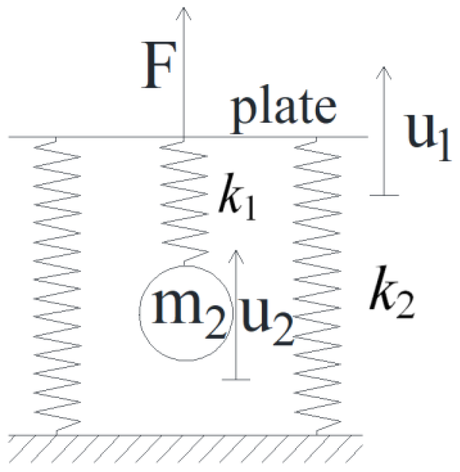
Figure 1 depicts a two-degree-of-freedom (2-DOF) mass-on-spring system, featuring a massless thin plate attached to the ground via two springs of constant stiffness. Beneath the plate, the mass is localized and supported by an auxiliary spring characterized by a particular stiffness
. Harmonic excitation with frequency
is applied to the thin plate. The displacement of the thin plate and the mass m
2 are denoted as
and
, respectively. The equations of motion governing the behavior of this spring-mass system are as Equation (1).
the frequency response functions
are derived to be Equation (2).
Using Newton’s second law, the effective stiffness of the system can be derived as Equation (3).
we note that the scenario arises when the excitation frequency
matches the natural frequency
associated with mass m, the effective stiffness
becomes infinitely large, resulting in a displacement
that approaches zero. Additionally, within a specific frequency range (denoted as (
,
)), the effective stiffness
is negative. The mechanism behind this negative effective stiffness involves creating shear forces that absorb vibration energy under resonant excitation.
In the academic field of structural dynamics and vibration control, we have identified a crucial phenomenon: when the external excitation frequency precisely matches the inherent resonance frequency of the auxiliary mass-spring subsystem, it triggers a potent resonance effect. The core advantage of this effect lies in its ability to generate a significant resistance that not only effectively counters the external excitation but also facilitates deep dissipation of vibration energy within the base structure. This specific frequency range, encompassing the resonance frequency and its adjacent spectrum, is termed the “stop band”. Within the meticulously designed stop band, notable changes occur in the propagation characteristics of elastic waves. Specifically, due to the resonance state of the auxiliary mass-spring subsystem, elastic waves experience intense interference effects as they attempt to traverse the base structure. This interference complicates and obstructs the wave’s propagation path, leading to a substantial decrease in propagation efficiency. More importantly, it further promotes energy dissipation within the structure. By meticulously adjusting various parameters of the auxiliary mass-spring subsystem, such as mass distribution, spring stiffness, and damping characteristics, we can achieve precise control over the position and width of the stop band. This control capability enables us to effectively suppress specific vibration frequencies, thereby significantly enhancing the seismic and fatigue resistance of structures. Furthermore, this strategy introduces new theoretical insights and technological approaches to the field of vibration control, exerting a profound impact on the development and application prospects of related disciplines.
3. Design of the Negative Stiffness Plate
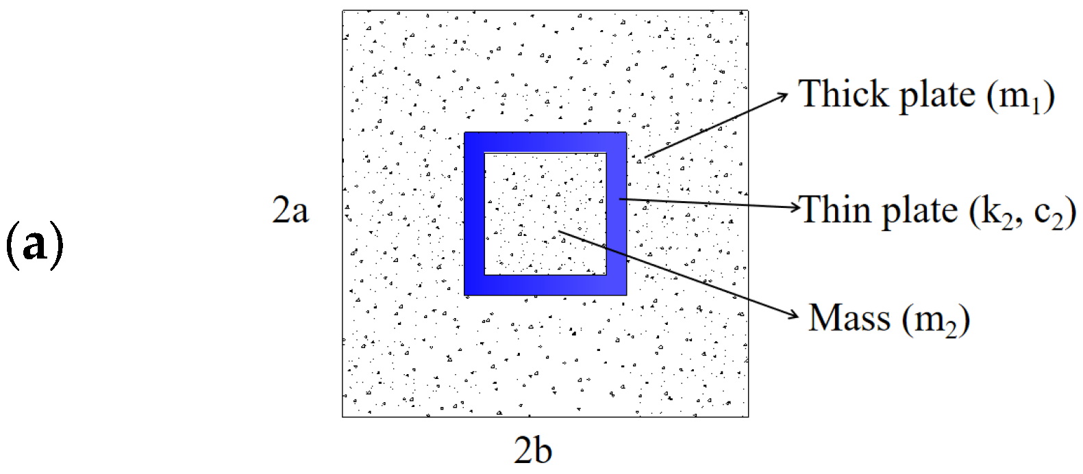
In the field of vibration control engineering, researchers have continuously explored new technologies and methodologies to address vibration issues arising from complex environments such as traffic loads and seismic activities. Based on the design concept of the two-degrees-of-freedom spring-mass system vibration absorber, this paper innovatively proposes a negative stiffness plate unit, providing a fresh perspective for solving the aforementioned problems. The structural design of the negative stiffness plate unit is illustrated in
Figure 2a. Its core lies in the ingenious integration of a mass-spring subsystem. This design enables each unit to be customized according to actual requirements, exhibiting precise local resonance frequencies. When external excitations act on the unit, the mass-spring subsystem responds rapidly and generates a significant amount of out-of-phase inertial forces. These forces cancel each other out at the microscopic scale, effectively reducing the internal stresses within the base plate and achieving the purpose of dissipating vibrations. In the actual production process of negative stiffness plates, rubber can be used as a damping material.
To more clearly demonstrate the mechanical characteristics of the device, we have simplified its representation, as shown in
Figure 2b. This simplified model not only retains the key design elements but also makes analysis and calculation more intuitive and efficient. Based on this, we further explored the possibility of assembling multiple replicas of the unit at the microscopic scale. By precisely controlling the layout and arrangement of each unit, we successfully constructed a plate with significant negative stiffness characteristics, as shown in
Figure 2c. In addition to innovations in structural design, we also integrated suitable damping materials within the dampers. This measure aims to further enhance the vibration suppression capabilities of the negative stiffness plate. When vibrations occur, the damping materials can absorb and dissipate a significant amount of vibration energy, thereby reducing the amplitude and propagation range of the vibrations. Experimental results indicate that by integrating suitable damping materials, the negative stiffness plate unit exhibits excellent performance in addressing vibrations caused by seismic activities.
In Equation (4), and represent the normal stresses along the x and y directions, respectively, and E and v are the material’s Young’s modulus and Poisson’s ratio. Subsequently, as shown in Equation (5), we denominate the momentum responses of the plate as M1, M2, and M6, and define its stress responses as N1, N2, N6.
In this context, D represents the bending stiffness of the material. Assuming that the sums of forces and moments along the x, y, and z directions must always be zero, the following relationships can be derived as Equation (6).
where
These signify the intensities of the lateral shear forces acting within the yz and xz planes, respectively.
Additionally, the kinetic energy
, elastic potential energy
, and non-conserved work
arising from external forces can be determined as outlined below Equations (8)–(10).
Then, based on the expanded Hamiltonian principle, the controlling equations for the infinite negative stiffness plate unit are deduced as Equation (11).
It is important to note that the discontinuity solely arises in the internal transverse shear forces, and this discontinuity is mathematically represented using a two-dimensional Dirac function. As a result, the governing equations Equation (12) for the base plate can be derived based on this representation.
Integrating Equation (7) and yields:
It should be noted that the loads have been removed in the process of integration. According to Equation (13), the base plate can be considered as a rigid body undergoing accelerated motion, while experiencing transverse shear forces and a focused force acting on its four boundaries.
The control equation for m
2 can be formulated as Equation (14) through the application of Newton’s second law of motion.
Illustrated in
Figure 2b, when an infinite plate comprising repetitive unit cells is impacted by a harmonic wave of a single frequency, the displacements of both the plate
and the vibration dampener
can be represented as Equation (15).
In this context, A and B stand for the magnitudes of vibrational oscillation,
and
represent the spatial frequencies along the x and y axes, respectively, while ω indicates the frequency of the wave. By incorporating Equation (15) into Equations (13) and (14), the resultant expressions can be recast in a matrix notation.
Equation (16) poses an eigenvalue challenge. By equating the determinant of the matrix within Equation (16) to zero, we can establish a connection between the wave numbers
,
and the frequency
of the wave [
3].
4. Stopband of the Negative Stiffness Plate
In the interdisciplinary field of structural dynamics and materials engineering, the negative effective stiffness property revealed by Equation (17) opens up a novel design approach for engineers, particularly in the development of negative stiffness plates with unique vibration suppression capabilities. Negative stiffness, this unconventional mechanical characteristic, when cleverly incorporated into structural design, can significantly reshape the dynamic behavior of structures. Notably, when the effective stiffness exhibits negative characteristics, the propagation mode of elastic waves within the structure undergoes a fundamental transformation. In this context, the phase velocity of the elastic waves (i.e., the advancement rate of the wave front) may run counter to the direction of the group velocity (representing the average rate of energy transmission), a trait that is rarely observed in conventional material systems.
Furthermore, when the frequency of external excitation approaches the natural resonant frequency of the mass-spring subsystem embedded within the structure (serving as an additional component), the subsystem triggers intense resonant phenomena. This resonant effect not only generates an effective damping force against external excitation, thereby reducing the dynamic stress borne by the structure, but also effectively disperses and dissipates the vibration energy within the base structure. This mechanism results in a significant suppression of elastic wave propagation within a specific frequency range (which we refer to as the “stop band”), preventing it from transmitting smoothly as in other frequency ranges. Therefore, by finely tuning the parameters of the mass-spring subsystem, we can precisely manipulate the location and width of the stop band, thereby achieving detailed control over the vibration characteristics of the structure.
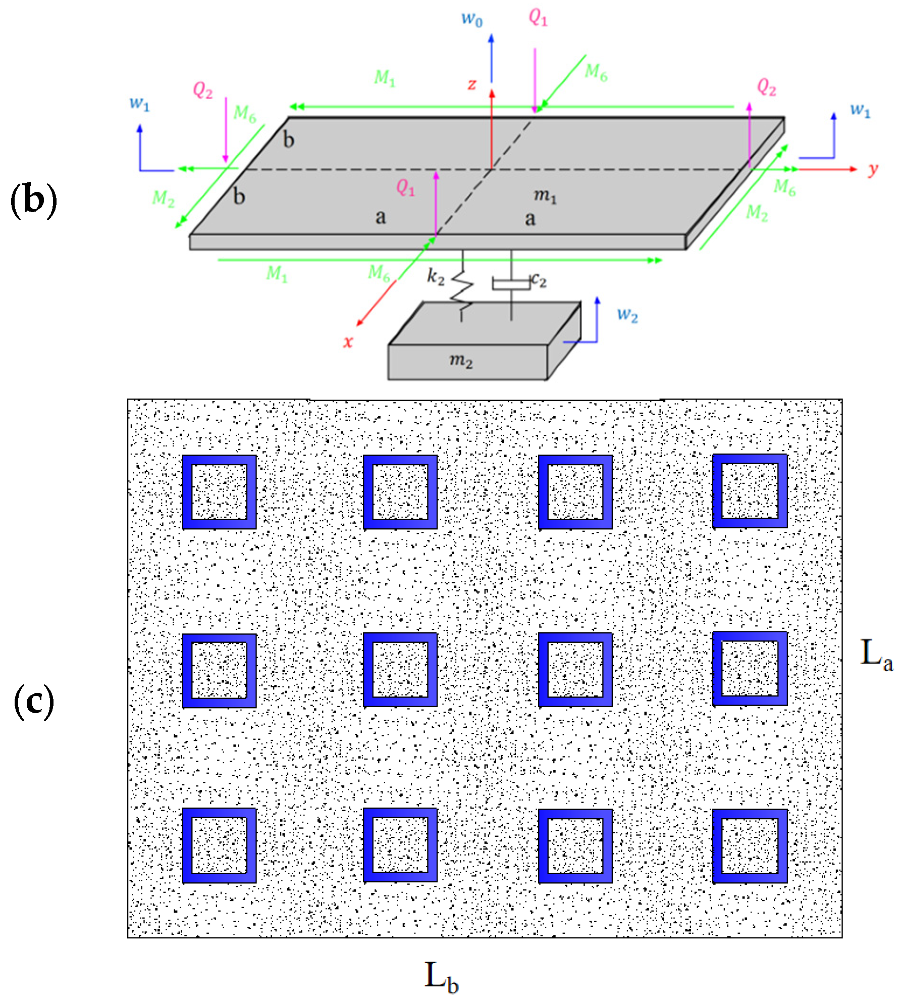
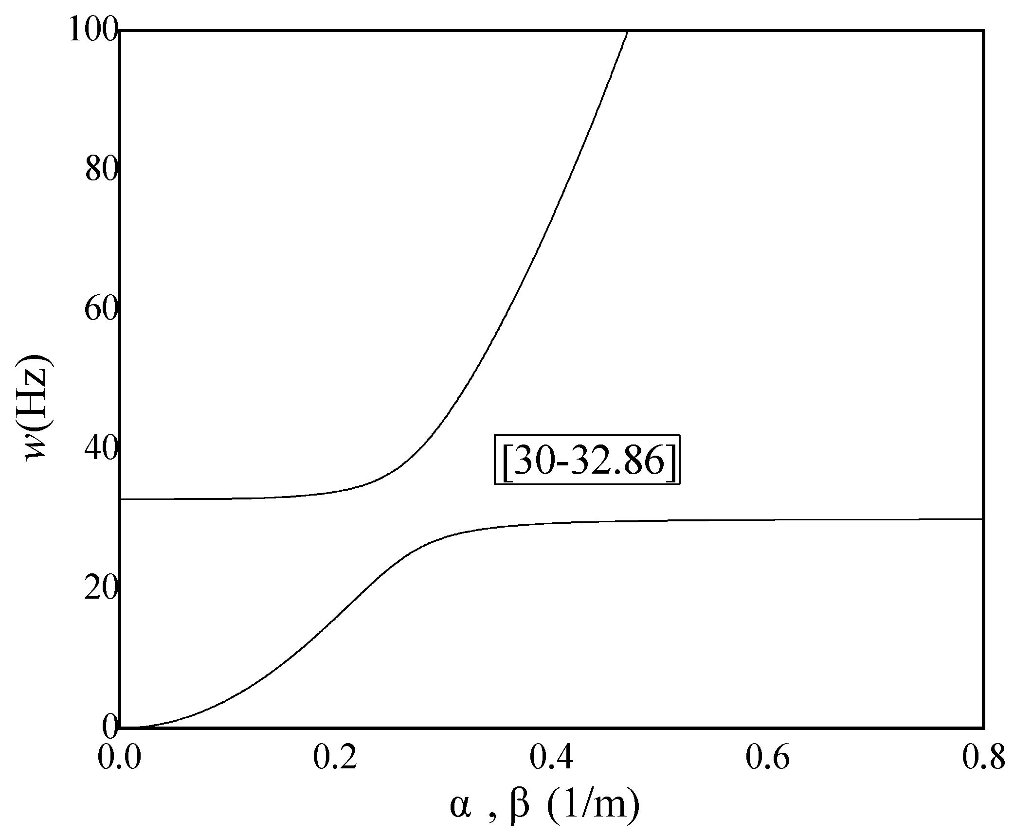
Assuming a positive real-valued frequency, Equation (17) can be resolved to determine equilibrium conditions. Referencing
Figure 1, the unit cell dimensions are set at 2a = 0.2 m, 2b = 0.2 m, and h = 10 mm, with a Young’s modulus of E = 69 GPa. Additional parameters such as the Poisson’s ratio
, mass density
, attached mass m2 = 0.1 kg, and the natural frequency
are also considered. By computing, the relationship between wave number
,
and wave frequency
is obtained. As depicted in
Figure 3, a stop band emerges between 30 Hz and 32.86 Hz, within which wave propagation is prohibited. This stop band aligns to the right of the local resonance frequency, attributed to the local vibration absorber’s ability to generate phase-shifted inertial forces, effectively absorbing vibrational energy.
5. Frequency Response Analysis of Negative Stiffness Plate
5.1. Frequency Response Analysis
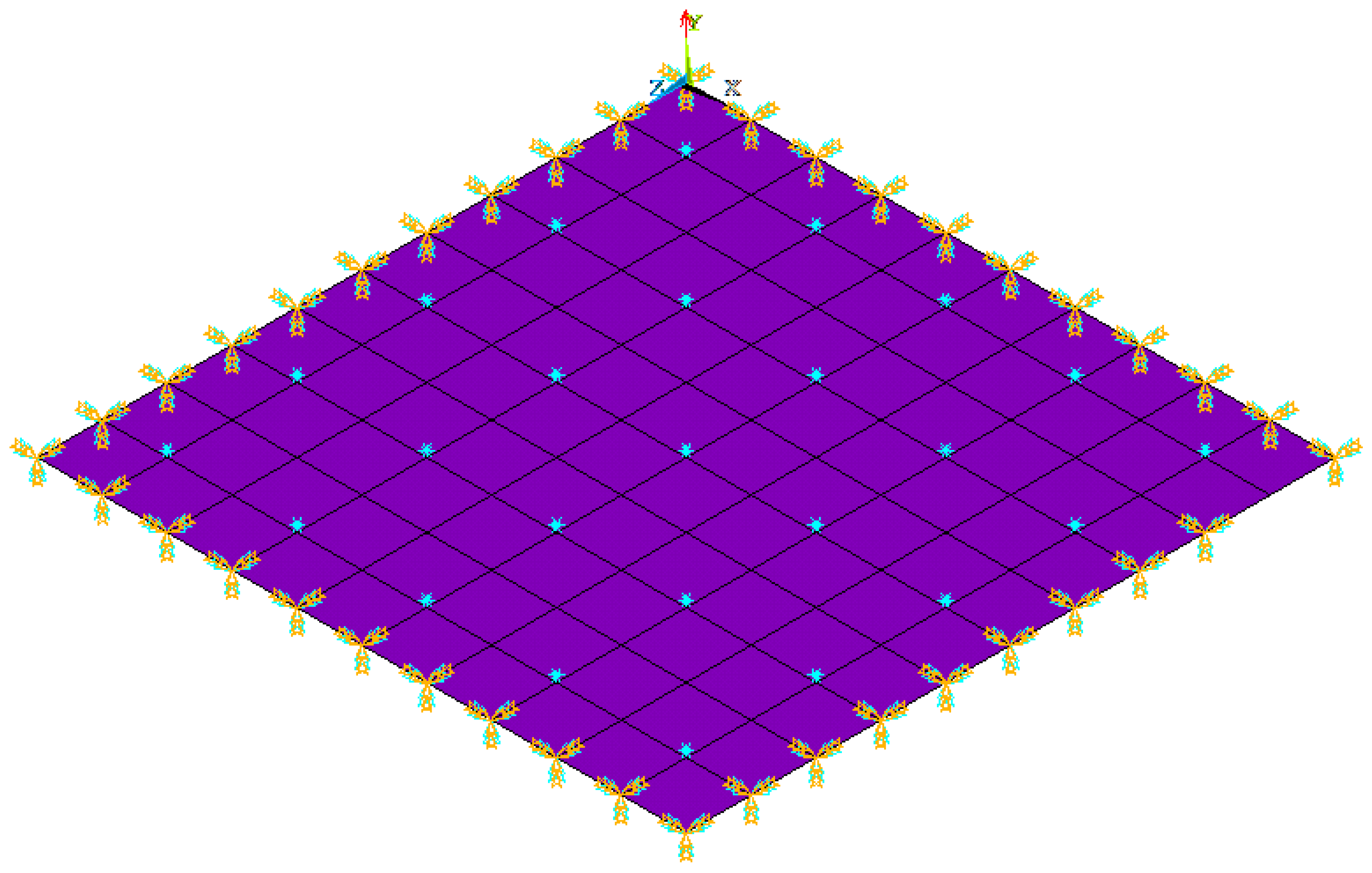
A crucial utilization of negative stiffness plates involves mitigating and dampening the impact of destructive waves that propagate due to events such as earthquakes, winds, noise, or explosions. To showcase the effectiveness of our novel frequency-responsive vibration absorber, we have crafted a negative stiffness plate with precisely tailored dimensions and material characteristics, as depicted in
Figure 4. The dimensions of the plate are La = 2 m along the X-axis, Lb = 3 m along the Y-axis, and h = 10 mm in thickness. The material properties include a Young’s modulus of E = 69 GPa, a Poisson’s ratio
, and a mass density
. Additionally, the plate has attached masses of m2 = 0.1 kg, a natural frequency
, and a damping ratio
.
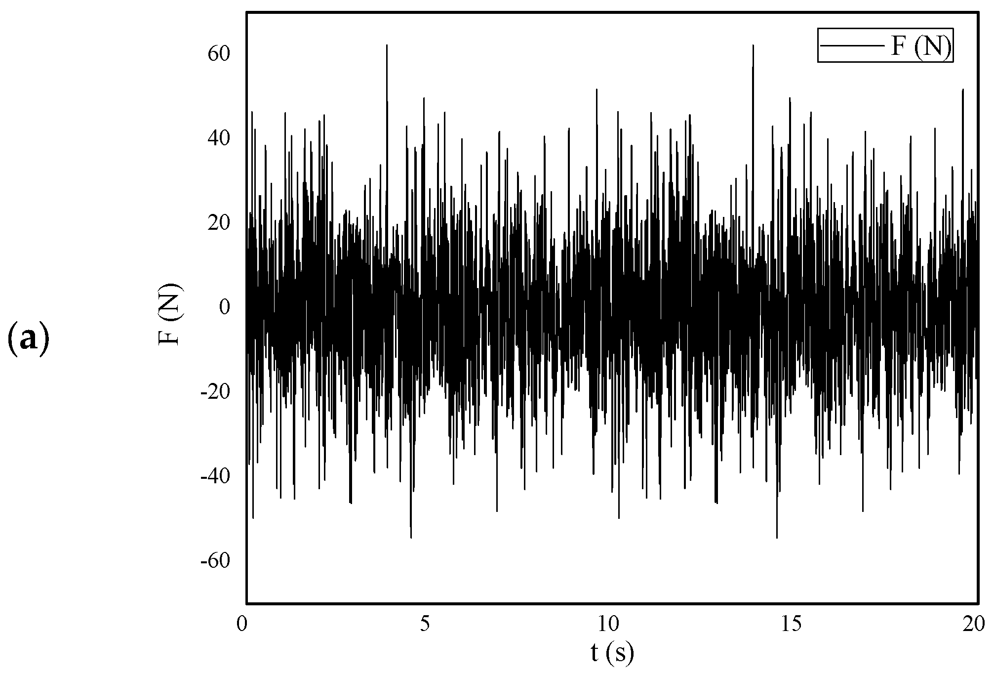
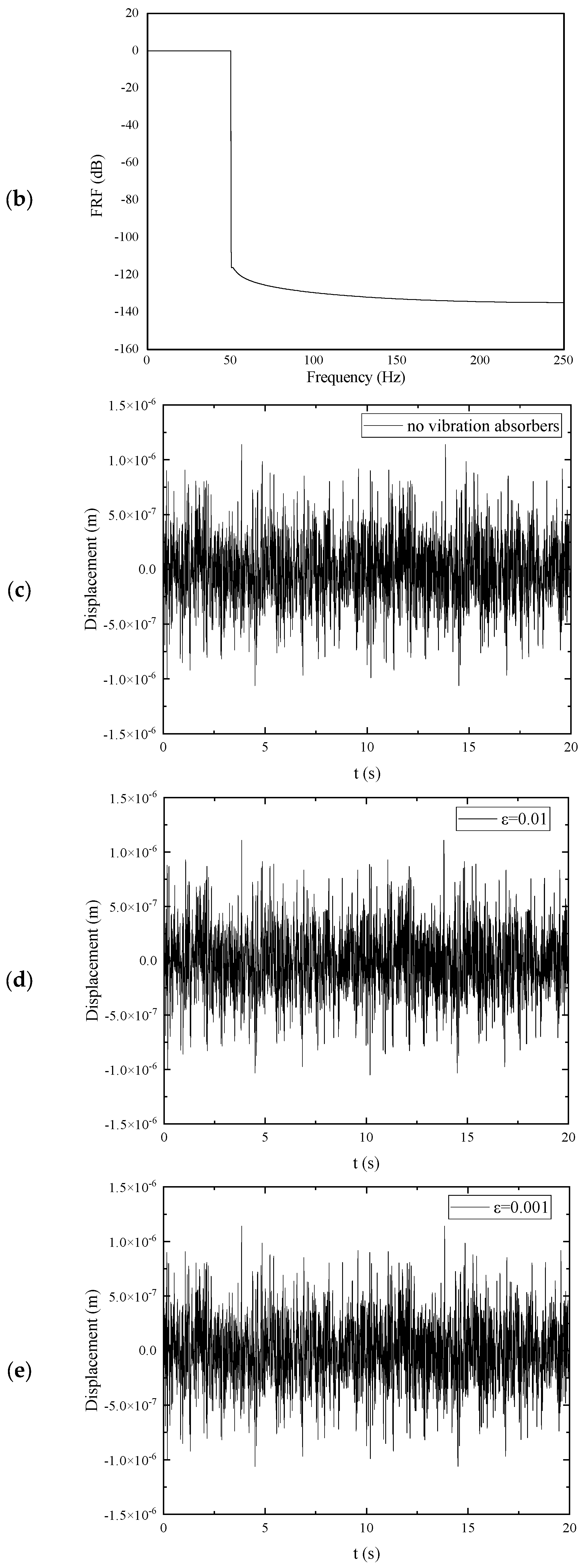
As shown in
Figure 5, If the damping of the absorber
, excitation force
at
,
, The variables
are uniform random numbers within the range of [−1, 1], it is shown in
Figure 5a. Then, the frequency response function (FRF) of excitation force can be predicted by frequency response analysis (see
Figure 5b), the displacement of the plate can be calculated based on the FE Model (see
Figure 5c–e). Furthermore, if the damping of the absorber
, through the application of finite element (FE) modeling and frequency response analysis, the frequency response function (FRF) of displacement can be accurately determined, as depicted in
Figure 5f. Upon analyzing the FRF, it becomes apparent that augmenting the damping coefficients of the absorbers results in a broadening of the stopband region and a notable decrease in the amplitudes of vibrations.
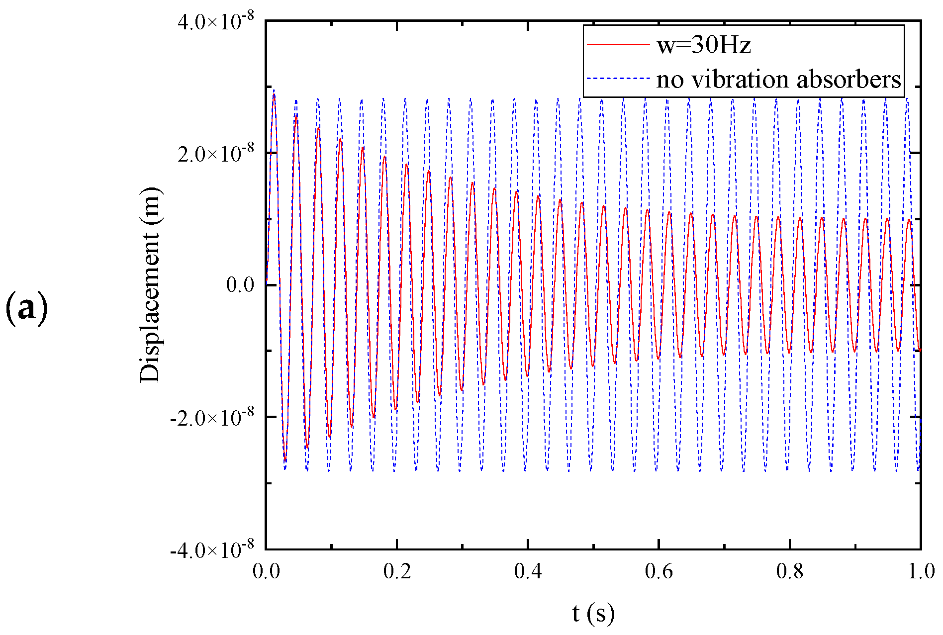
5.2. Harmonic Excitation
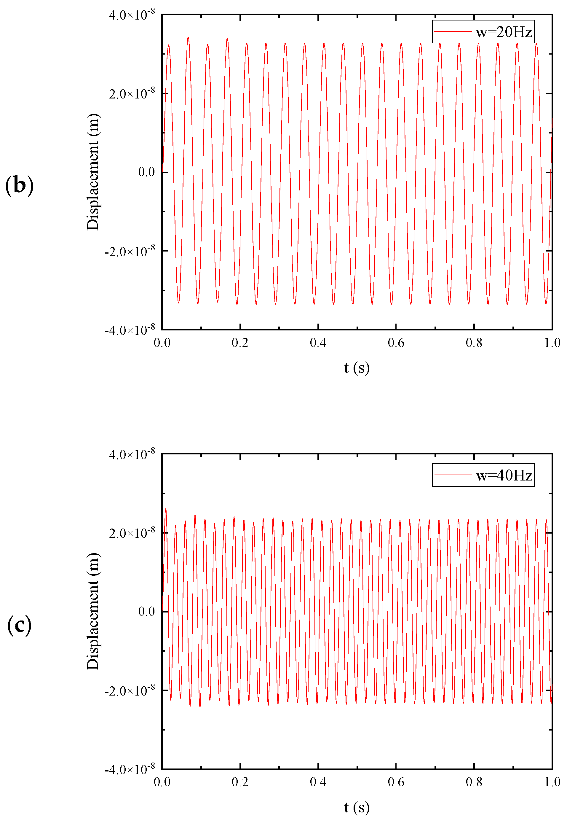
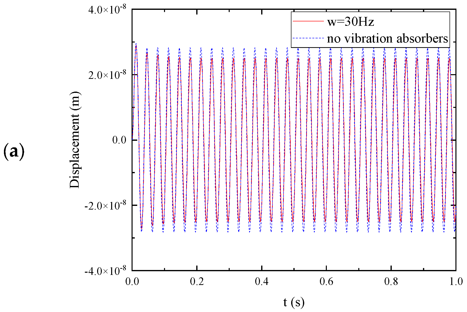
To validate the effectiveness of the negative stiffness plate, it is necessary to evaluate its dynamic responses under various excitation force frequencies, both within and outside the stopbands. For
, excitation force
at
, and time step
,
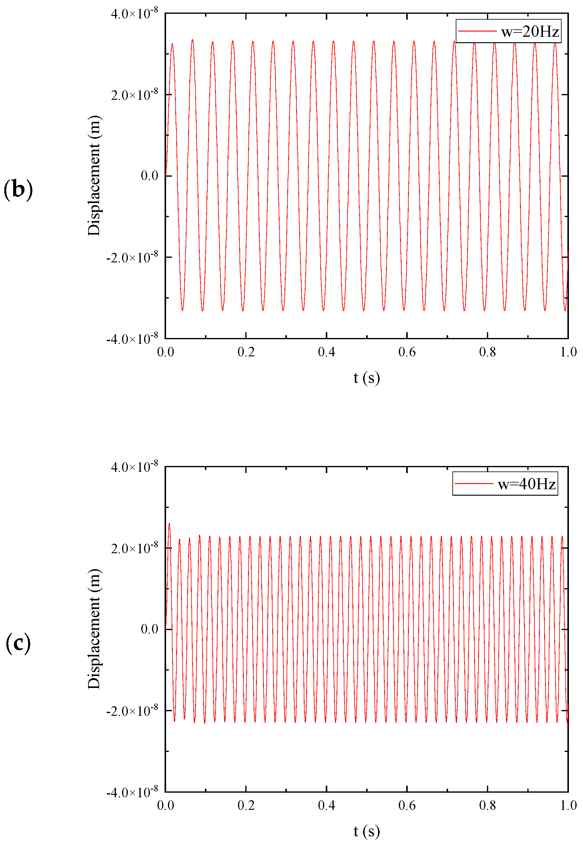
Figure 5 present the transient responses of the plate under excitation frequencies of 20 Hz, 30 Hz, and 40 Hz, respectively. Additionally,
Figure 6b,c depict the results obtained from harmonic excitations, showing the scenarios where the frequency is beneath and above the local resonance frequency of the vibration absorber. In these cases, the absorbers are unable to effectively stop wave propagation due to the mismatch between the excitation frequency and the resonant frequency of the absorbers. Conversely,
Figure 6a demonstrates the results for harmonic excitation
at a frequency within the stopband. In this scenario, the vibration absorbers are able to absorb the structural vibration, effectively mitigating its impact. To further investigate the effect of damping on vibration mitigation, if the damping of the absorber
,
Figure 7 present the transient responses of the plate under the same excitation frequencies (20 Hz, 30 Hz, and 40 Hz) but with increased damping in the absorbers. By comparing
Figure 6a with
Figure 7a, it becomes evident that increasing the damping of the absorbers can reduce their efficiency in mitigating vibrations.
6. Earthquake Excitation
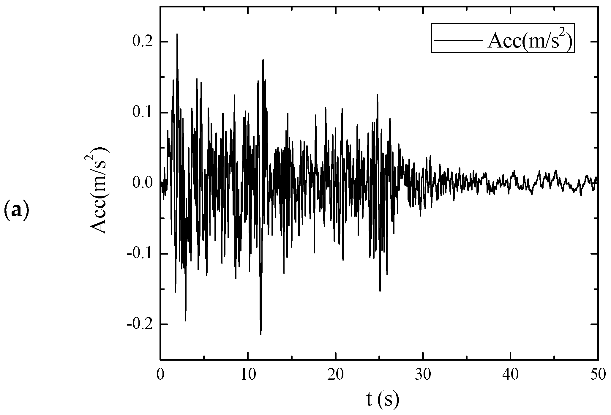
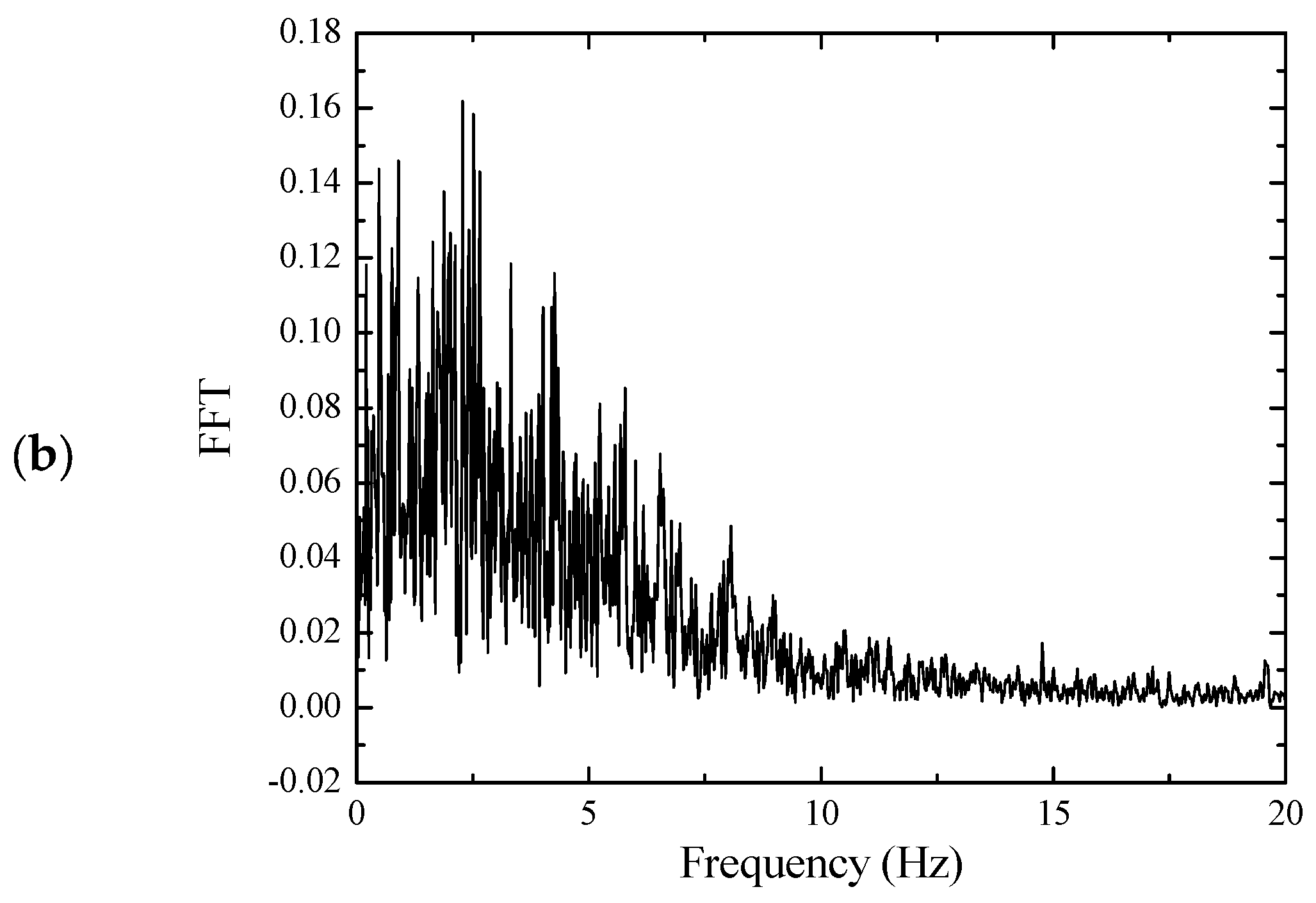
The El-centro wave is selected as seismic excitations, as shown in
Figure 8a. The spectral characteristics of its seismic waves are shown in
Figure 8b. Because the seismic load is not a single frequency of harmonic excitation, so how to design the vibration frequency of the substructure of the negative stiffness plate is the key to the structural shock absorption.
According to previous research [
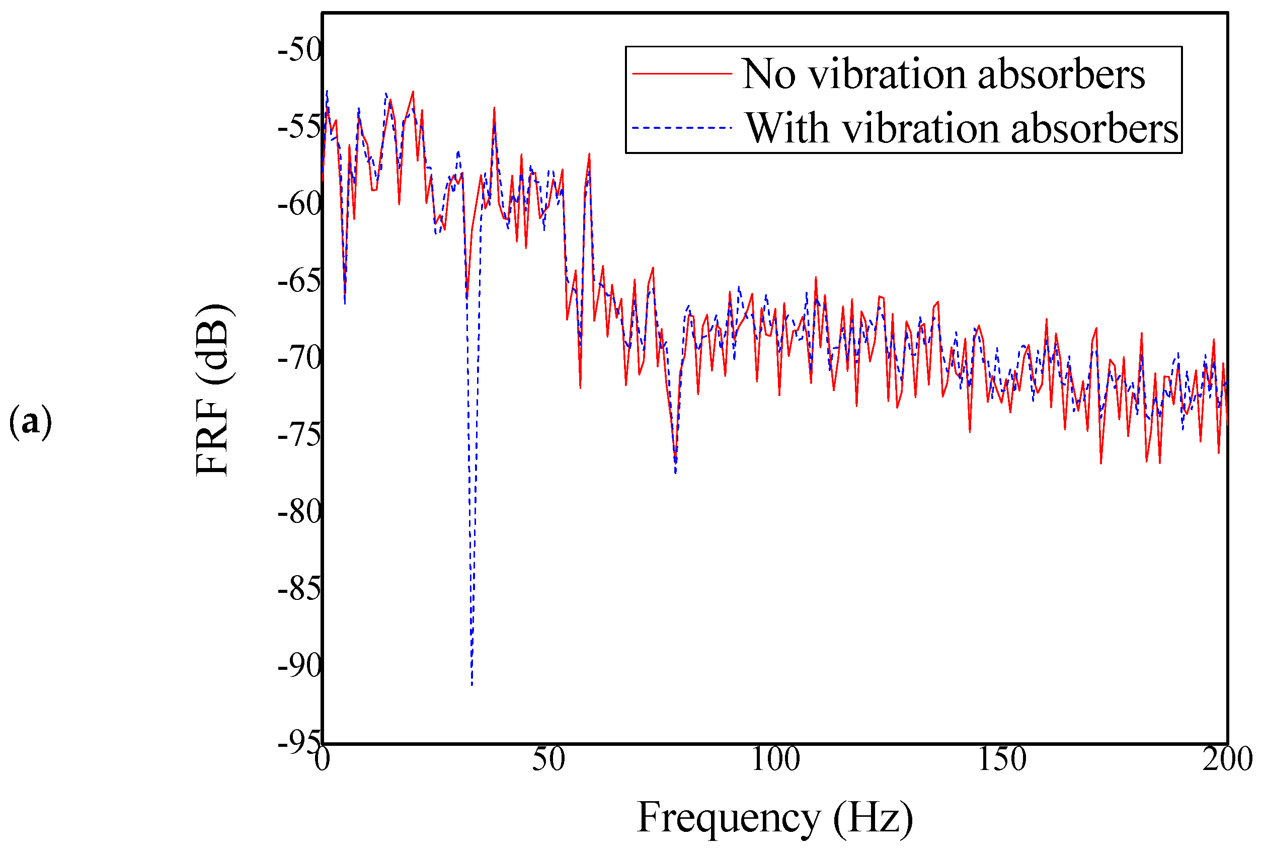
3], when the resonance frequency of the substructure is set close to the main frequency of the main structure, it can minimize the structural vibration caused by earthquakes. As shown in
Table 1 and
Figure 9, this article compares the vibration of negative stiffness plates with and without substructures and finds that compared to ordinary plates, the overall average displacement of negative stiffness plates under seismic action is reduced by 31.34%, and the maximum displacement is reduced by 19.10%.
7. Conclusions
The preceding information provides a comprehensive overview of the working mechanism and modeling technique of the negative stiffness plate. Based on this analysis, several key conclusions can be drawn:
The negative stiffness plate operates on the principle of conventional metamaterial plates with attached mass-spring-damping subsystems. These subsystems generate locally resonant vibrations that produce inertial forces that counteract external loads, effectively inhibiting elastic wave propagation in the host plate.
For a single-stopband negative stiffness plate, a stopband emerges near the resonant frequency of the unit cell. Increasing the damping of the resonators within the plate can slightly broaden this stopband and effectively reduce the response amplitude of the host plate, enhancing its vibration-damping capabilities.
When subjected to seismic waves with a broad distribution of external excitation frequencies, the negative stiffness plate demonstrates significant potential for reducing structural vibration. Specifically, when the natural frequency of the substructure aligns with the vibration frequency of the main structure, the plate can significantly mitigate the vibration caused by earthquakes.
Author Contributions
J.H. independently led and was responsible for this research. Conceptualization, R.Z. and J.H.; methodology, R.Z.; software, R.Z.; validation, J.H., Z.Z. and R.Z.; formal analysis, Z.Z. and R.Z.; investigation, J.H.; resources, J.H.; data curation, S.H.; writing—original draft preparation, Z.Z. and J.H.; writing—review and editing, Z.Z. and J.H.; visualization, R.Z.; supervision, J.H.; project administration, J.H.; funding acquisition, J.H. All authors have read and agreed to the published version of the manuscript.
Funding
This research was funded by the Shenzhen High-level Talents Research Start-up Fund (No. RC2022-004), “2024 Doctoral Research Startup Project of Shenzhen Institute of Information Technology” (Grant No. SZIIT2024KJ030), Key Laboratory of Land Satellite Remote Sensing Application, Ministry of Natural Resources (Grant No. KLSMNR-G202222) and Youth Innovation Talent Project in Guangdong Provincial Universities (Grant No. 2024KQNCX174). The viewpoints in this paper represent only the author’s opinion and do not represent the views of the fund committee.
Data Availability Statement
The original contributions presented in the study are included in the article, further inquiries can be directed to the corresponding authors.
Conflicts of Interest
Author Rumian Zhong is employed by the Shenzhen Institute of Information Technology. Author Jie Huang is employed by the Shenzhen Xindahui Technology Engineering Co., Ltd. The remaining authors declare that the research was conducted in the absence of any commercial or financial relationships that could be construed as potential conflicts of interest.
References
- Veselago, V.G. The electrodynamics of substances with simultaneously negative values of permittivity and permeability. Sov. Phys. Usp. 1968, 4, 509–514. [Google Scholar] [CrossRef]
- Pendry, J.B. Negative refraction makes a perfect lens. Phys. Rev. Lett. 2000, 85, 3966–3969. [Google Scholar] [CrossRef] [PubMed]
- Zhong, R.; Zong, Z.H.; Pai, P.F. Metamaterial I-girder for vibration absorption of composite cable-stayed bridge. J. Eng.Mech. ASCE 2018, 144, 04018045. [Google Scholar] [CrossRef]
- Zhong, R.; Zong, Z.H.; Pai, P.F. Multi-stopband negative stiffness composite column design for vibration absorption. Thin-WalledStruct 2019, 144, 106330. [Google Scholar] [CrossRef]
- Watts, C.M.; Liu, X.; Padilla, W.J. Metamaterial electromagnetic wave absorbers. Adv. Mater. 2012, 24, 98–120. [Google Scholar] [CrossRef]
- Bozhevolnyi, S.I.; Volkov, V.S.; Devaux, E.; Laluet, J.-Y.; Ebbesen, T.W. Channel plasmon subwavelength waveguide components including interferometers and ring resonators. Nature 2006, 440, 508–511. [Google Scholar] [CrossRef]
- Cheng, Y.; Xu, J.; Liu, X. One-dimensional structured ultrasonic metamaterials with simultaneously negative dynamic density and modulus. Phys. Rev. B 2008, 77, 045134. [Google Scholar] [CrossRef]
- Sun, C.T.; Kim, B.J.; Bogdanoff, J.L. On the derivation of equivalent simple models for beam- and plate-like structures in dynamic analysis. AIAA Dyn. Spec.Conf. 1981, 523–532. [Google Scholar] [CrossRef]
- Yang, Z.; Dai, H.; Chan, N.; Ma, G.; Sheng, P. Acoustic metamaterial panels for sound attenuation in the 50–1000 Hz regime. Appl. Phys. Lett. 2010, 96, 041906. [Google Scholar] [CrossRef]
- Yu, D.; Liu, Y.; Zhao, H.; Wang, G.; Qiu, J. Flexural vibration band gaps in Euler–Bernoulli beams with locally resonant structures with two degrees of freedom. Phys. Rev. B 2006, 73, 064301. [Google Scholar] [CrossRef]
- Zhang, S.; Yin, L.; Fang, N. Focusing ultrasound with an acoustic metamaterial network. Phys. Rev. Lett. 2009, 102, 194301. [Google Scholar] [CrossRef] [PubMed]
- Zhu, R.; Liu, X.N.; Huang, G.L.; Huang, H.H.; Sun, C.T. Microstructural design and experimental validation of elastic metamaterial plates with anisotropic mass density. Phys. Rev. B 2012, 86, 144307. [Google Scholar] [CrossRef]
- Pai, P.F.; Peng, H.; Jiang, S. Acoustic metamaterial beams based on multi-frequency vibration absorbers. Int. J. Mech. Sci. 2014, 79, 195–205. [Google Scholar] [CrossRef]
- Peng, H.; Pai, P.F. Acoustic metamaterial plates for elastic wave absorption and structural vibration suppression. Int. J. Mech. Sci. 2014, 89, 350–361. [Google Scholar] [CrossRef]
- Diaz, A.R.; Haddow, A.G.; Ma, L. Design of band-gap grid structures. Struct. Multidiscip. Optim. 2005, 29, 418–431. [Google Scholar] [CrossRef]
- Sun, H.; Du, X.; Pai, P.F. Theory of Metamaterial Beams for Broadband Vibration Absorption. J. Intell. Mater. Syst. Struct. 2010, 21, 1085–1101. [Google Scholar] [CrossRef]
- Pasala, D.T.R.; Sarlis, A.A.; Reinhorn, A.M.; Nagarajaiah, S.; Constantinou, M.C.; Taylor, D. Apparent-weakening in SDOF yielding structure using negative stiffness device: Experimental and analytical study. J. Struct. Eng. 2015, 141, 04014130. [Google Scholar] [CrossRef]
- Pasala, D.T.R.; Sarlis, A.A.; Nagarajaiah, S.; Reinhorn, A.M.; Constantinou, M.C.; Taylor, D. Adaptive negative stiffness: A new structural modification approach for seismic protection. J. Struct. Eng. 2013, 639, 1112–1123. [Google Scholar] [CrossRef]
- Yao, S.; Zhou, X.; Hu, G. Experimental study on negative effective mass in a 1D mass-spring system. New J. Phys. 2008, 10, 043020. [Google Scholar] [CrossRef]
- Sun, F.F.; Wang, M.; Nagarajaiah, S. Multi-objective optimal design and seismic performance of negative stiffness damped outrigger structures considering damping cost. Eng. Struct. 2021, 229, 111615. [Google Scholar] [CrossRef]
- Huang, H.H.; Sun, C.T.; Huang, G.L. On the negative effective mass density in acoustic metamaterials. Int. J. Eng. Sci. 2009, 47, 610–617. [Google Scholar] [CrossRef]
- Cheng, Z.; Shi, Z.; Mo, Y.L.; Xiang, H. Locally resonant periodic structures with low-frequency band gaps. J. Appl. Phys. 2013, 114, 033532. [Google Scholar] [CrossRef]
- Liu, X.N.; Hu, G.K.; Huang, G.L.; Sun, C.T. An elastic metamaterial with simultaneously negative mass density and bulk modulus. Appl. Phys. Lett. 2011, 98, 251907. [Google Scholar] [CrossRef]
- Choi, J.; Cho, T.; Bae, S.G.; Park, H.S. Development and practical application of locally resonant metamaterials for attenuation of noise and flexural vibration of floors in residential buildings. J. Build. Eng. 2022, 57, 104907. [Google Scholar] [CrossRef]
- Liu, Z.; Rumpler, R.; Feng, L. Broadband locally resonant metamaterial sandwich plate for improved noise insulation in the coincidence region. Compos. Struct. 2018, 200, 165–172. [Google Scholar] [CrossRef]
- Chowdhury, S.; Banerjee, A.; Adhikari, S. Optimal negative stiffness inertial-amplifier-base-isolators: Exact closed-form expressions. Int. J. Mech. Sci. 2022, 218, 107044. [Google Scholar] [CrossRef]
- Pierre, J.; Boyko, O.; Belliard, L.; Vasseur, J.O.; Bonello, B. Negative refraction of zero order flexural Lamb waves through a two-dimensional phononic crystal. Appl. Phys. Lett. 2010, 97, 121919. [Google Scholar] [CrossRef]
- Smith, D.R.; Pendry, J.B.; Wiltshire, M.C.K. Metamaterials and negative refractive index. Science 2004, 305, 788–792. [Google Scholar] [CrossRef]
- Pai, P.F. Highly Flexible Structures: Modeling, Computation and Experimentation; AIAA: Reston, VA, USA, 2007. [Google Scholar]
- Zhong, R.; Zong, Z.; Pai, P.F.; Ruan, X.; Deng, H. Instantaneous frequency tracking method for composite cable-stayed bridge. Mech. Syst. Signal Pr. 2018, 100, 43–56. [Google Scholar] [CrossRef]
- Pai, P.F. Metamaterial-based broadband elastic wave absorber. J. Intell. Mater. Syst. Struct. 2010, 21, 517–528. [Google Scholar] [CrossRef]
| Disclaimer/Publisher’s Note: The statements, opinions and data contained in all publications are solely those of the individual author(s) and contributor(s) and not of MDPI and/or the editor(s). MDPI and/or the editor(s) disclaim responsibility for any injury to people or property resulting from any ideas, methods, instructions or products referred to in the content. |
© 2025 by the authors. Licensee MDPI, Basel, Switzerland. This article is an open access article distributed under the terms and conditions of the Creative Commons Attribution (CC BY) license (https://creativecommons.org/licenses/by/4.0/).


