4.1. Diagnosis
4.1.1. SME Description
The SME is a construction company located in Tacna, Peru, that specializes in residential building projects, with the mission of providing the population of the city with access to proper housing, and with the vision of creating adequate living spaces in collaboration with the government through the use of bonds destined for this purpose. Currently, the SME has completed the delivery of eleven projects, while four others are under implementation and three are pending. The management of its projects follows a traditional approach which comprises several stages. Initially, the planning and basic studies stage is carried out, followed by the preparation of the preliminary project, after which the basic design and construction design are developed. Simultaneously, the corresponding permits are processed with the corresponding public entities. Subsequently, the measurements, construction budget and schedule are prepared. With all this documentation, the financing is processed with the financial institution.
Once these stages are completed, the contract is formalized with the contractor, with the SME assuming 64% of the work and the contractor 36%. A traditional contract is used to establish the contract amount, terms, penalties, methods of payment, project manager, and annexes that include blueprints, technical specifications, descriptive reports, measurements, construction budget and schedule. Upon completion of that stage, execution of the work begins, the progress of which is monitored by means of monthly valorization reports until the project is completed.
The SME’s main resources include both human and material resources. The company has a staff of 10 employees, while the contractor has 13 employees. In addition, they rely on the collaboration of 10 service providers to carry out operations efficiently. SME’s organization chart is composed of the General Management, Deputy General Management, Administration and Finance (accounting, logistics and treasury), and the Technical Area (architecture and engineering: projects and project manager).
Regarding material resources, the SME has 7 computers, 2 laptops, 1 plotter, and 3 printers. All workstations operate with the Windows 10 operating system. The software applications used include AutoCAD 2020, Microsoft Excel 2019, SketchUp 2022, Lumion 2022, Microsoft Word 2019. Regarding information management, data and document management is mainly carried out manually and through Google Drive, where all project documentation is stored and shared with each area of the SME. Communication is carried out through WhatsApp groups, temporary meetings, and phone calls.
4.1.2. Description of the Case Study
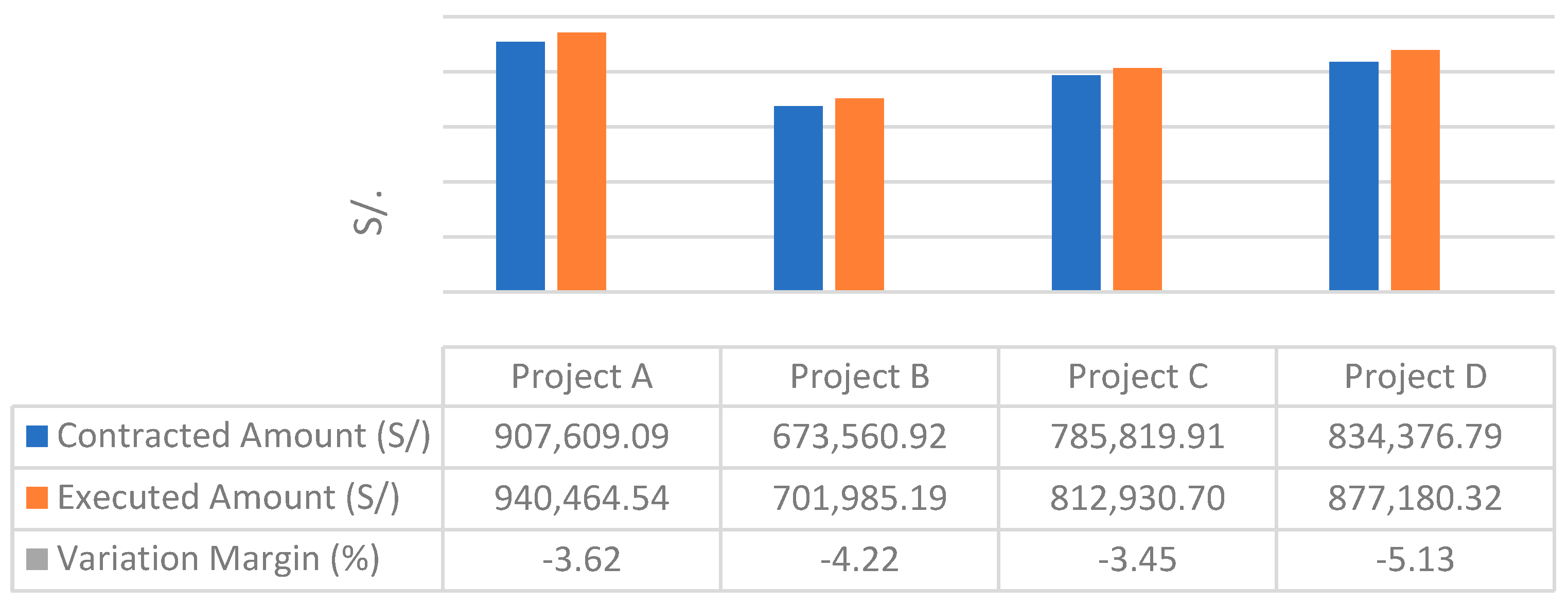
The documentation of the SME projects was reviewed and four projects were identified, such projects presented significant deviations in budget and deadlines with respect to the project design. These inconsistencies showed deficiencies in the SME management system. These are detailed in
Figure 1 and
Figure 2.
Figure 1 shows the comparison between the contract amount and the executed amount of four SME projects. The variation margin between these amounts ranges from −3.45% to −5.13%, with Project D having the largest margin. These results are consistent with the findings of Asvadurov, Varilla, Brindado, Brown, Knox, and Ellis [
1], who reported cost overruns of up to 37% in global projects.
Figure 2 presents the comparison between the contractual schedule and the executed schedule for the same four projects. The percentage of variations in schedule varies between −26.29% and −39.67%, with Project D showing the largest gap. These findings are consistent with those reported by Asvadurov, Varilla, Brindado, Brown, Knox, and Ellis [
1], who found gaps of up to 53% in global projects.
Based on the indicators presented, Project D was chosen as the case study because it was the one that showed the greatest variation, which allows an in-depth analysis of the causes and possible solutions. This project is a residential building in Tacna, Peru, of 5 levels plus a rooftop, with a 128 m2 lot and a roofed area of 617.87 m2. The first level includes 2 garages, 1 storage room, 1 solid waste room, 1 staircase, and 1 apartment. The second, third, fourth, and fifth levels have a typical layout with 1 staircase and 2 apartments. The roof terrace consists of 1 rooftop terrace and 1 area for drying clothes. The structure is framed with confined masonry. The sanitary installations include a pumping system, cold water distribution, and drainage networks. The electrical installations include independent single-phase current for each apartment and data and communications outlets. Project development was carried out in the traditional manner and under a traditional contract. The programmed budget was S/834,376.79, while the executed budget reached S/877,180.32. The programmed deadline was 305 days, and the final execution deadline was 426 days.
4.1.3. Typical Management Problems
Following the analysis of the SME documentation and the case study, 11 interviews were conducted with different project participants including contractors, professionals from different specialties, labor personnel, and suppliers. The following question was formulated to them: What do you consider to be the main reasons for cost overruns and delays in the SME projects? Based on all this information, the following management problems were identified:
P1: Deficiencies in the blueprints.
P2: Deficiencies in the measurement and budget.
P3: Weak team communication, coordination, and collaboration.
P4: Modifications and/or reworks.
P5: Existence of hidden flaws that generate additional work.
P6: Cost overruns in the construction process.
P7: Delays due to poor planning in material supply and errors in material purchasing.
P8: Lack of clarity and transparency in the contract and its clauses.
P9: Lack of incentives for good practices.
It is evident that most of the identified problems could have been avoided during the design stage. Therefore, we will focus on solving these problems by incorporating tools from the BIM and IPD methodologies.
4.2. Optimization Proposals
With the purpose of addressing the problems identified in the diagnosis, the tools of both BIM and IPD methodologies, which were compiled through a detailed bibliographic review in
Section 2, are presented below. It should be mentioned that these tools allow for better project management and can be integrated into a working model that includes BIM and IPD.
4.2.1. H1: Contractual Management–Standardized Contract
To develop an optimal project, it is crucial to have clear and well-defined contracts. This tool is related to the 1D dimension of BIM, as well as to aspects of project conception under IPD standards.
Based on the criteria of Yabar-Ardiles, Sanchez-Carigga, Vigil, Málaga, and Zevallos [
26],
Table 3 analyzes and identifies the deficiencies in the case study contract of Project D, using the incentives and tools recommended by NEC4 ECC as a reference. (New Engineering Contract—Engineering and Construction Contract).
Table 3 presents the shortcomings of the traditional contract in the case study in terms of clarity and stimulus for good management. Some clauses contain insufficient information, which can lead to disputes, and there is no adequate risk distribution. These problems coincide with the key aspects that NEC4 considers essential for good management. It is therefore recommended to implement NEC4 ECC clauses to address these deficiencies, supported by studies such as the Managing Reality compendium [
33] and Yabar-Ardiles, Sanchez-Carigga, Vigil, Málaga, and Zevallos [
26], which also suggests their use to foster collaborative environments. The clauses are shown below.
Establishes a written communication system with defined response times for notifications such as early warnings and inconsistencies, among others. Each party maintains its own record to facilitate problem prevention and resolution.
Allows any party to notify events that may affect the price, schedule, or execution of the project. Notification should be made as soon as the event becomes known so that meetings are held to manage changes efficiently and failure to do so may result in penalties.
Covers situations where the contractor is entitled to compensation, as long as the problem is not attributable to the contractor. The contractor must submit to the Project Manager the corresponding solution and quotation for the Compensation Event. The Manager will evaluate this proposal and, if necessary, instruct the contractor to consider more efficient alternatives. Timely notifications of these events are essential to avoid penalties and to promote a collaborative resolution of the problems.
Clause X12 promotes multi-party collaboration and rewards compliance or improvement of key performance indicators (KPIs). X20 establishes incentives for the contractor based on KPIs defined by the counterparty. X6 provides incentives for early completion of work. Main Options C and D, which operate under a Target Price Contract, compare the final price of the works with a target price set in the contract. If there is a positive balance in this comparison, it is distributed between the parties as agreed.
Offers dispute mitigation and resolution options, with it as the first method. This board visits the project site, inspects the work, offers recommendations, and resolves disputes before they are formally referred to a court of law.
The flexibility of NEC4 ECC facilitates the integration of BIM and IPD through clauses such as C.16, which fosters collaboration between the parties from the beginning of the project; X10, which regulates information management; X20, which regulates shared objectives and performance bonuses; and C.Z which allows contractual aspects to be customized according to the needs of the project.
The implementation of these improvements will contribute to establishing contractual clarity with defined responsibility, incentivizing good practices, optimizing project performance, and reducing cost overruns and delays through compensation and exchange control mechanisms.
4.2.2. H2: Common Data Environment (CDE)
Communication is fundamental to establishing collaborative environments. In the case study, Drive, WhatsApp, and emails were used; however, with the implementation of BIM models, there is a need to improve this aspect. The Common Data Environment (CDE) is the leading platform for documentation, quality control, and project information management. It aims to streamline model reviews, facilitate change management, improve communication, and foster collaboration, as well as ensure information security and prevent document duplication. It is crucial that the CDE is available to all stakeholders, with clearly defined roles and access levels.
In this context, according to the literature reviewed, Trimble Connect, a cloud-based platform, was recommended. It meets these requirements and organizes all project documentation, 3D models, 2D drawings, PDF files, spreadsheets, and RFIs, in a single accessible location. This eliminates the need to compress and email files, ensuring that all team members work with the latest version of documents and models. This reduces errors and ensures transparency, accessibility, and traceability of project information, improving collaboration by allowing an overview and specific details. In addition, all movements are registered, which facilitates the control of changes and updates.
Trimble Connect Sync allows you to synchronize files from your computer, network drive, or mobile device to the cloud, keeping everything up to date in both locations. The To-Do tool improves task management and project communication by allowing comments, questions, and concerns to be documented and assigned to team members, who receive email notifications. Tasks are customized with titles, descriptions, due dates, and other relevant information, which can be linked to specific objects in the model reviewed by all participants. Trimble Connect offers a free version with 10 GB of cloud storage; for more capacity, professional licenses must be purchased.
Its implementation improves team communication and coordination, ensuring access to up-to-date information. In addition, it avoids unnecessary modifications and rework by maintaining a single source of truth, reducing delays caused by poor planning, and optimizing workflow.
4.2.3. H3: Software
The efficiency of project development depends to a large extent on the technical capabilities of the software used. In the case study, a traditional AutoCAD approach was used for documentation development, so it is essential to have adequate resources to ensure trouble-free development. According to the literature reviewed, there are several key software categories in this process, such as modeling, coordination, measurement and budgeting, scheduling, and visualization. Tools such as Revit and Navisworks are prominent examples in the construction field.
Revit is the leading platform for building BIM information models. Its ability to automatically coordinate project changes and share a database of files among multiple users makes it indispensable.
On the other hand, Navisworks stands out as a BIM model viewer that covers all phases of the project. It facilitates the interoperability of 3D models during design and construction, improving visualization and interference detection. Its ability to read almost any 3D file format and handle large files makes it a crucial tool for project management.
These tools were applied in the Project D case study, demonstrating that the use of these tools contributes to minimizing deficiencies in plans, measurements, and budgets through precise and coordinated models. Reduce modifications and rework by detecting interference in the design phase. Avoid hidden defects that generate additional work, improving the quality and consistency of the project.
4.2.4. H4: Work Teams
In projects, it is essential that teams have complementary skills, share a common purpose, pursue performance objectives, and are mutually accountable for the result. In the case study, the work team during the design stage did not include the contractor up until the execution of the work, which is a practice that could be improved. We reviewed the literature and recommended that the team should consist of, at a minimum, the owner or a representative, an architect or engineer, a designer, and a general contractor or project manager. Early inclusion of the contractor facilitates the incorporation of diverse perspectives, optimizes deliverables, and reduces the need for later modifications.
Likewise, it is necessary to have trained professionals with experience in BIM and IPD methodologies software. To ensure effective management of these methodologies, an adequate budget should be allocated for the continuous training of these professionals.
Early contractor integration contributes to: improving project planning and execution; reducing deficiencies in plans, measurements, and budgets by incorporating construction experience from the beginning; reducing cost overruns in the construction phase; and avoiding delays due to poor planning, providing a more realistic view of execution.
4.2.5. H5: ICE Sessions
The Integrated Concurrent Engineering (ICE) sessions are fundamental to successful project development. In the case study, they were limited to temporary meetings, indicating the need to improve this approach. The literature was reviewed and is recommended that ICE Sessions be held face-to-face in a suitable space, equipped with chairs, projectors, large tables, electrical connectors, lighting and ventilation control, and a whiteboard. This environment should encourage active participation and use the best technological tools available to ensure transparency and trust among participants.
ICE sessions should be held at least once a week, with the active participation of all those involved in the project. During the design phase, the frequency can be increased twice a week or even daily, depending on the size of the project. These meetings allow the integration of all project specialties and improve overall understanding, thus optimizing the design procedures.
Clear agendas should be established to align the team with the project objectives. Agendas should be shared in advance with everyone involved to allow for brainstorming solutions in case problems arise. Pre-sessions help to reduce latency times and to make faster decisions.
ICE sessions enable: better decision-making and early problem-solving through real-time interdisciplinary meetings; optimization of communication, coordination, and collaboration by bringing all key parties together in structured sessions; reduction in modifications and rework by identifying errors before execution; reduction in delays due to poor planning, speeding up decisions, and approvals.
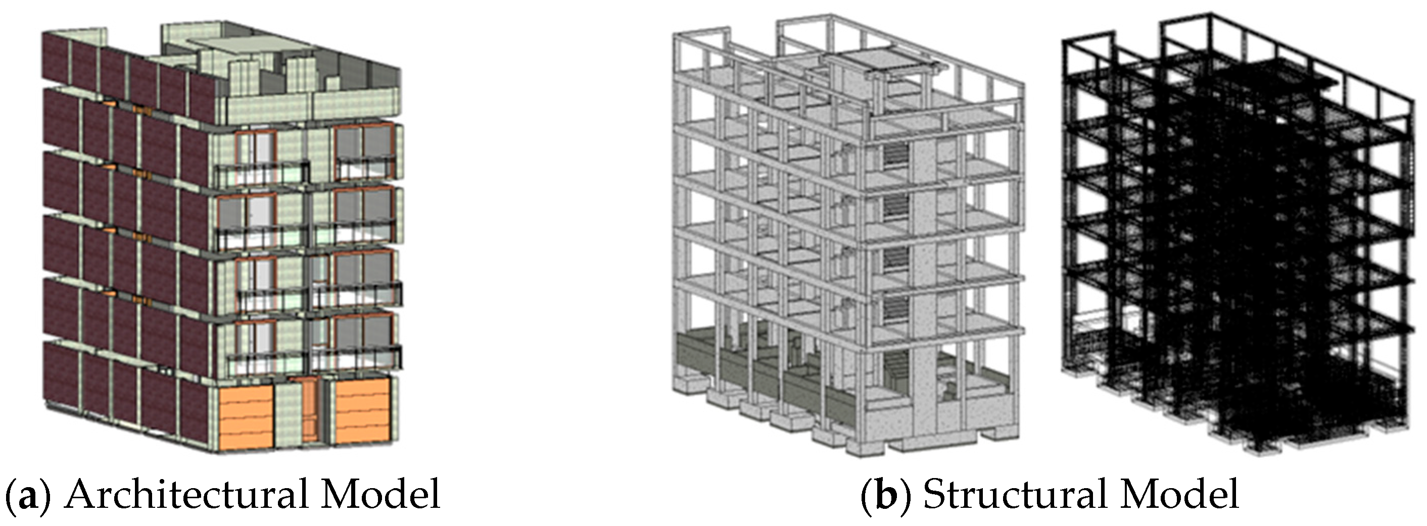
4.2.6. H6: 3D Model
The three-dimensional representation of the drawings, together with the parametric representation of each building component, forms the 3D Model. In the case study, a traditional approach with 2D drawings was used; therefore, it is recommended to implement 3D Models to improve visualization, coordination, project presentation, design review, and incompatibility detection, thus optimizing planning and productivity control.
Based on the criteria of Maciel, de Souza and Oliveira [
5], Project D plans were modeled in Revit, in separate templates for each specialty, with linkage between them. This methodology allowed keeping the templates lighter so that they would not interfere with the computer processing. In addition, by separating the specialties, the possibility of accidental changes in the models of other disciplines was prevented, a risk that can arise when everything is modeled in a single template. The models of each specialty are shown in
Figure 3.
After completing the modeling, the models were integrated into Navisworks for interference detection, identifying recurring problems such as overlapping windows, doors, pipes, and devices with structural elements. These findings support previous studies that highlight the importance of BIM in the compatibility of multidisciplinary projects. It is crucial to prioritize interferences according to their impact. To solve these problems, ICE sessions should be scheduled with all stakeholders to make shared decisions.
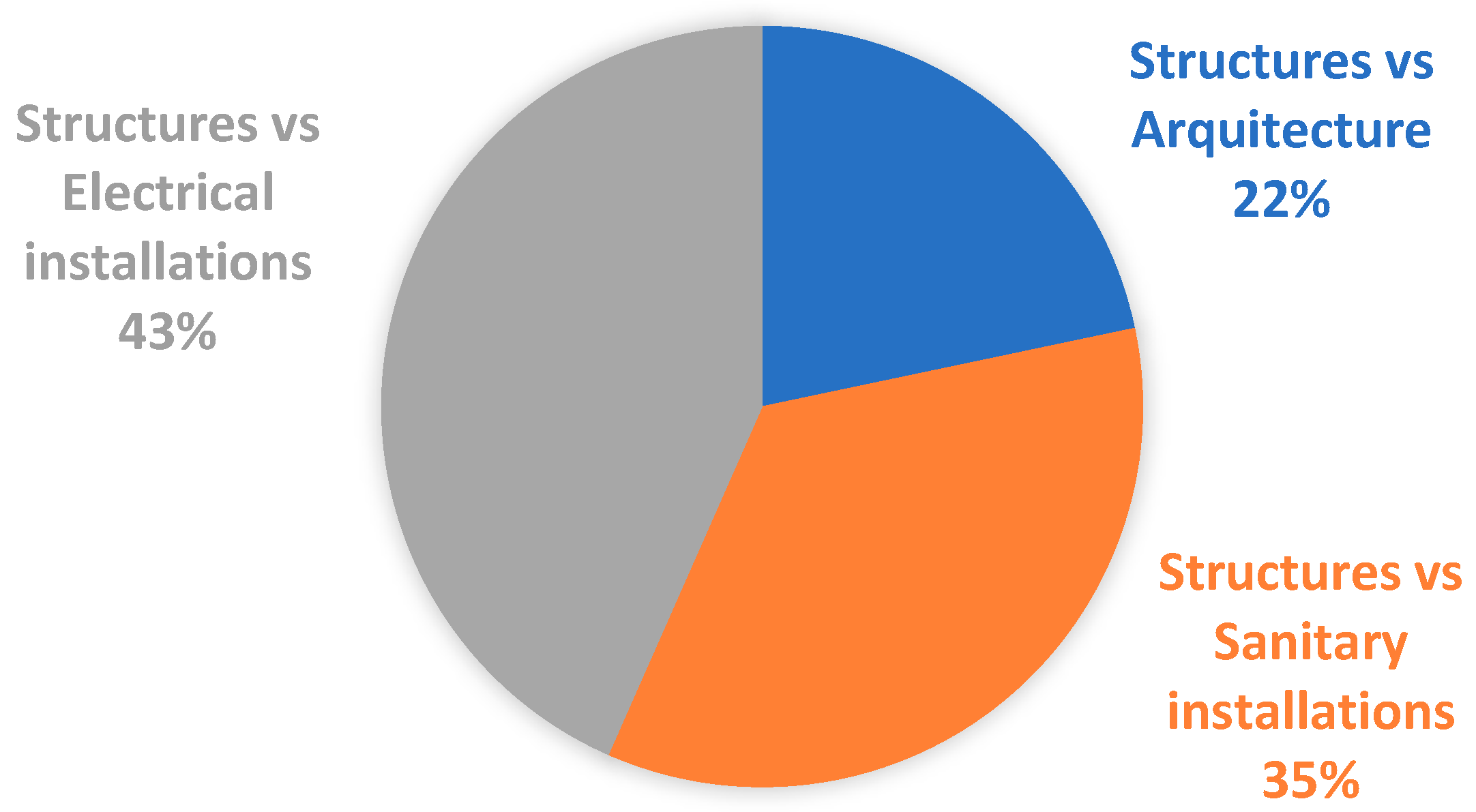
In
Figure 4, percentages of interferences between specialties are shown, 64 interferences (22%) for Structures vs. Architecture, 103 interferences (35%) for Structure vs. Sanitary installations and 128 interferences (43%) between Structure vs. Electrical installations, for a total of 295 interferences.
As shown in
Figure 4, “Structure VS Electrical Installations” interferences represent the highest percentage, mainly due to the presence of pipes and devices in structural elements. To minimize these interferences, it is essential to coordinate the installation of electrical systems with that of the structures. Placing outlets, switches, and switchgear on plates, columns, and beams should be avoided, and instead, they should be located on the walls.
On the other hand, Maciel, de Souza and Oliveira [
5] identified in their study that the highest number of interferences was between Structures vs. Sanitary Installations, which also underlines the importance of using BIM methodology for better coordination.
The interference per square meter indicator was calculated considering the total interference detected between the total roofed area of the project, as shown in
Table 4.
Table 4 shows that there are 0.48 interferences per square meter of roofed area, which indicates a significant amount in relation to the total area. This finding is crucial to assess the impact on the budget, as it highlights the need to identify possible modifications that could have affected the original budget. Systematic analysis by overlaying models in Navisworks facilitates the early detection of problems and contributes to more efficient project execution by reducing rework and delays during construction.
The integration of the 3D model enables a reduction of deficiencies in plans, measurements, and budgets, improving the precision of the design. It also enables the minimization of modifications and rework by detecting errors before execution and avoids hidden defects that generate cost overruns, through verifications prior to the start of the work.
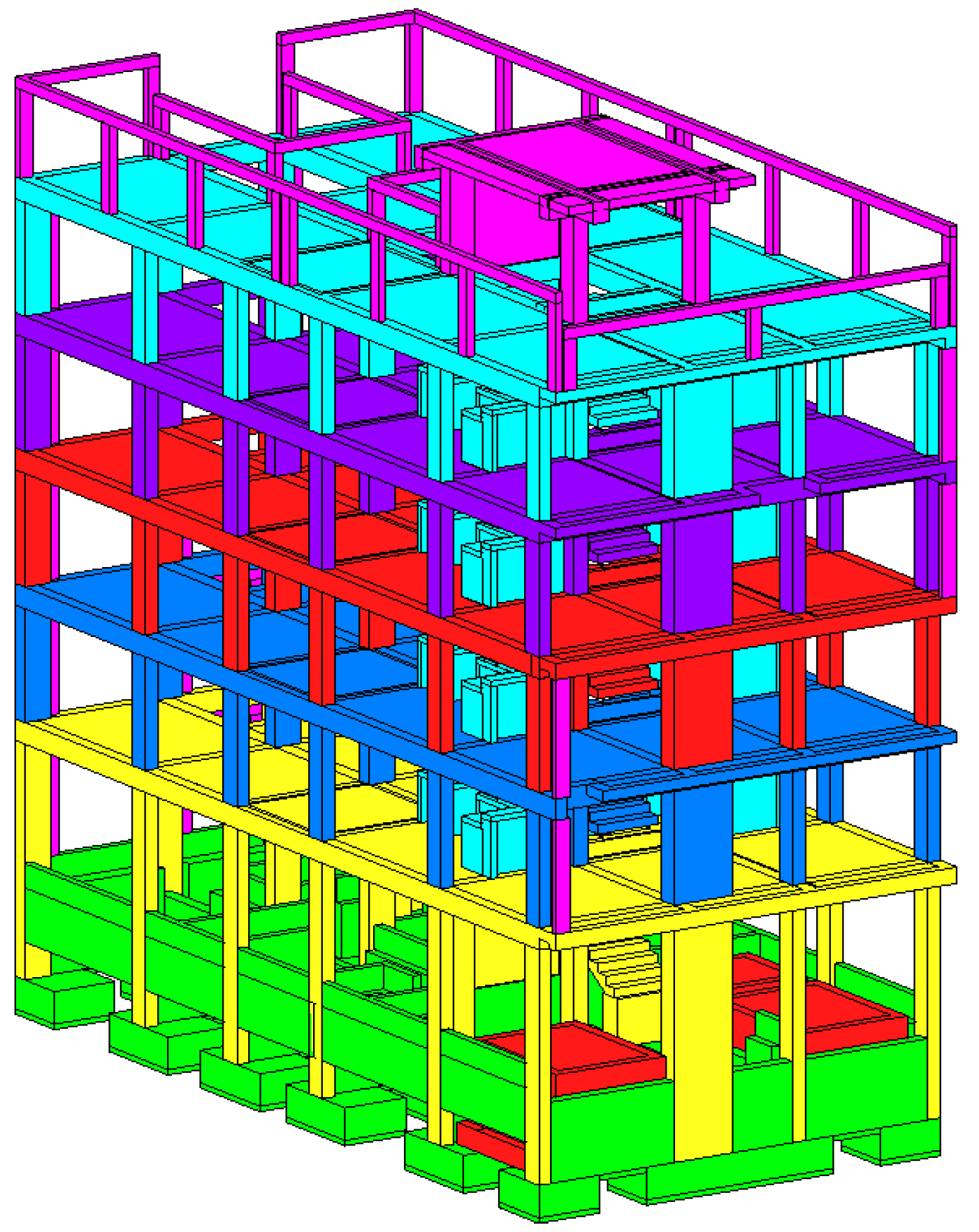
4.2.7. H7: 4D Model
Time factor determines a sequence of execution for each element of the project, which allows for controlling its dynamics and anticipating possible difficulties, thus increasing performance and complying with the established deadlines. Implementing the 4D model in the planning and control of a project can be of great help to ensure compliance with time and budget, being essential to constantly monitor the progress of the project.
Figure 5 shows the monthly sectorization of the structure specialty of Project D, according to the contractual schedule. The colors indicate the monthly progress of the project. This methodology can also be applied to other specialties.
Sectorization or 4D simulation allows the generation of project progress control reports using the BIM model. This approach is more valued by clients compared to a Gantt chart, as it facilitates a better understanding and visualization of project progress.
The 4D model contributes to: visualizing and optimizing the construction sequence, improving planning; reducing delays due to poor planning, by anticipating conflicts and adjusting scheduling; reducing modifications and rework; simulating the construction process before execution; optimizing team coordination, by visually showing the interaction of tasks over time.
4.2.8. H8: 5D Model
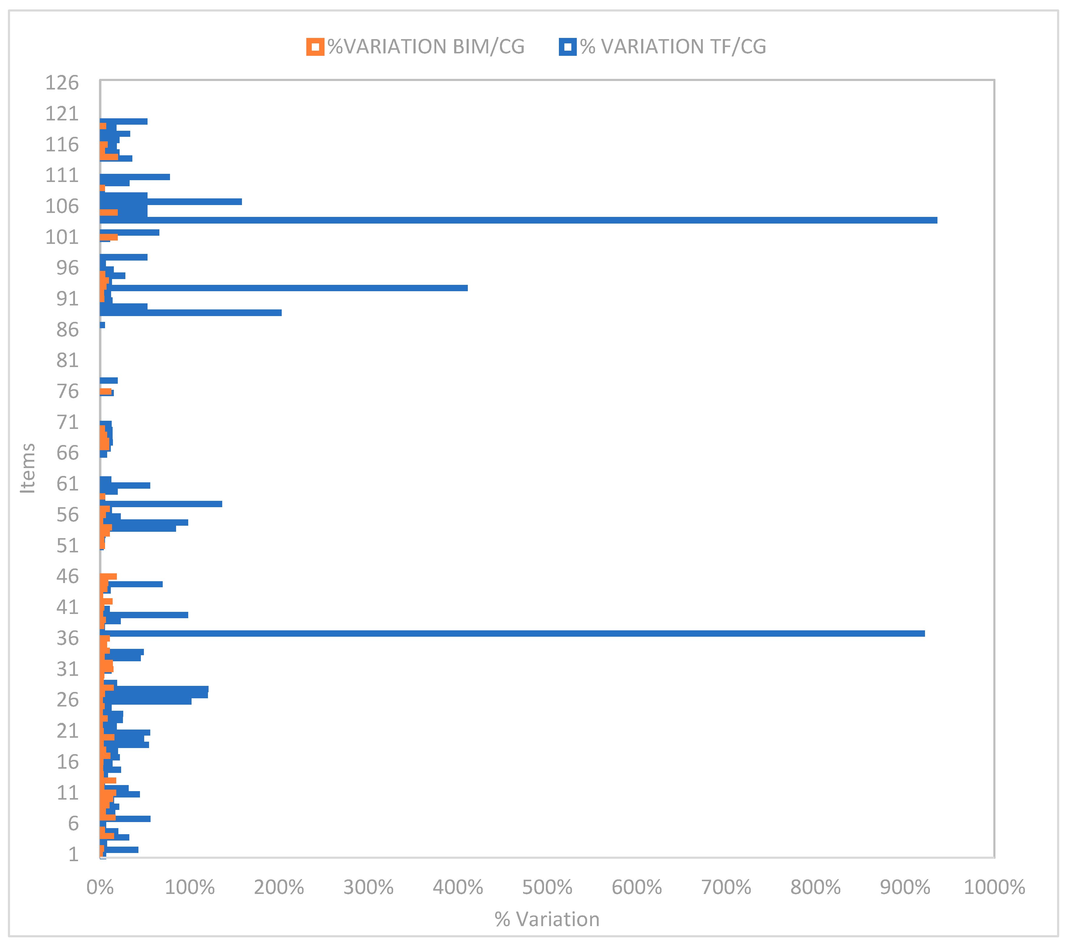
5D Model covers the obtaining of measurements and cost estimation, allowing precise control over the financial information and improving the profitability of the project’s investment. After generating the 3D models of the different specialties the D project was measured with BIM in order to compare the measurements obtained with the data of the technical file.
A total of 126 items were analyzed, of which 34 items are for structures, 22 for architecture, 47 for sanitary installations, and 23 for electrical installations.
Table 5 details the variation of the items by specialty.
As shown in
Table 5, the specialty with the greatest variation is structures, followed by architecture, and more than 50% of all specialties have variation, which is a detrimental factor for the budget.
Table 6 shows the total number of project items and the items with variation in the measurement, comparing the BIM methodology, and the traditional methodology.
Of the total number of items analyzed with the BIM methodology, 73.81% (93 items) show variation with traditional metrics, and only 26.19% (33 items) show no variation at all. These findings show the accuracy and efficiency of the use of BIM in the management of costs and measurements within the project.
A comparison was carried out between the costs of the traditional methodology (items extracted from the file), and the cost obtained by using the BIM methodology. It was observed that the items with variations in the measurement also experienced changes in the costs. This is detailed in
Table 7.
Table 7 shows that the total cost of the project, according to the technical file, which is S/804,430.48; while the cost using BIM tools is S/761,924.32, which represents a difference of S/42,506.16. This difference indicates an optimization of 5.28% with respect to the traditional method. In comparison, Chirinos and Pecho [
34] reported an optimization of 1.97%, which reinforces the effectiveness of BIM implementation in cost optimization.
The use of the 5D model allows: More accurate estimates throughout the project. Reduction of cost overruns, by linking work quantities with budgets in real time. Avoid costly modifications and rework by detecting inconsistencies from the design phase. To promote good practices in the financial management of the project.
Through
Table 8 and
Table 9, the estimated cost of implementing the BIM and IPD methodologies for the case study was analyzed. The implementation of BIM and IPD requires previous knowledge, so a training cost will be considered. This cost was obtained from the course “Project Management through IPD and BIM” of the Continuous Education Center of ESPOL.
Moreover, the cost of modeling and management of the application of the BIM methodology and the extraction of metrics in Revit 2023 software is detailed, the hours worked in the development of the BIM model of the case study were counted, which were 10 weeks (250 h) with a working day of 5 h per day. A monthly salary of S/3341.00 was assumed according to Diar Ingenieros S.A., according to a work shift of 48 h per week for 4 weeks, resulting in a rate of S/17.40 per man hour.
With all this data, it is possible to calculate the return on investment (ROI) of the implementation of BIM and IPD methodologies, which will allow us to evaluate their profitability. ROI according to Cabrera and Quiroz [
35] is determined by relating net income to the cost of implementation.
Table 9 shows a return-on-investment percentage of 394.41%, which means there is a return of S/3.94 for each S/1.00 invested in the implementation of BIM and IPD. In comparison, Cabrera y Quiroz [
35] reported a 109% return for the BIM methodology. This suggests that the BIM and IPD methodologies offer a significantly higher return compared to the traditional methodology.


