1. Introduction
Urban underground development has intensified globally, driven by rapid population growth and the demand for sustainable transportation systems. Subway tunnels excavated in soil–rock composite strata face great challenges due to the inherent heterogeneity of geological materials and the prevalence of natural or inner defects. Composite strata, characterized by alternating layers of soil and rock, exhibit abrupt transitions in mechanical properties, leading to stress concentration and differential deformation under external loads [
1,
2]. Such geological complexity is further exacerbated by defects, including voids, fractures, weak interlayers, and material discontinuities, which act as stress concentrators and pathways for groundwater infiltration [
3,
4,
5]. The instability of tunnels in these strata poses significant risks, including localized collapse, water inrush, and structural failure, threatening construction safety (
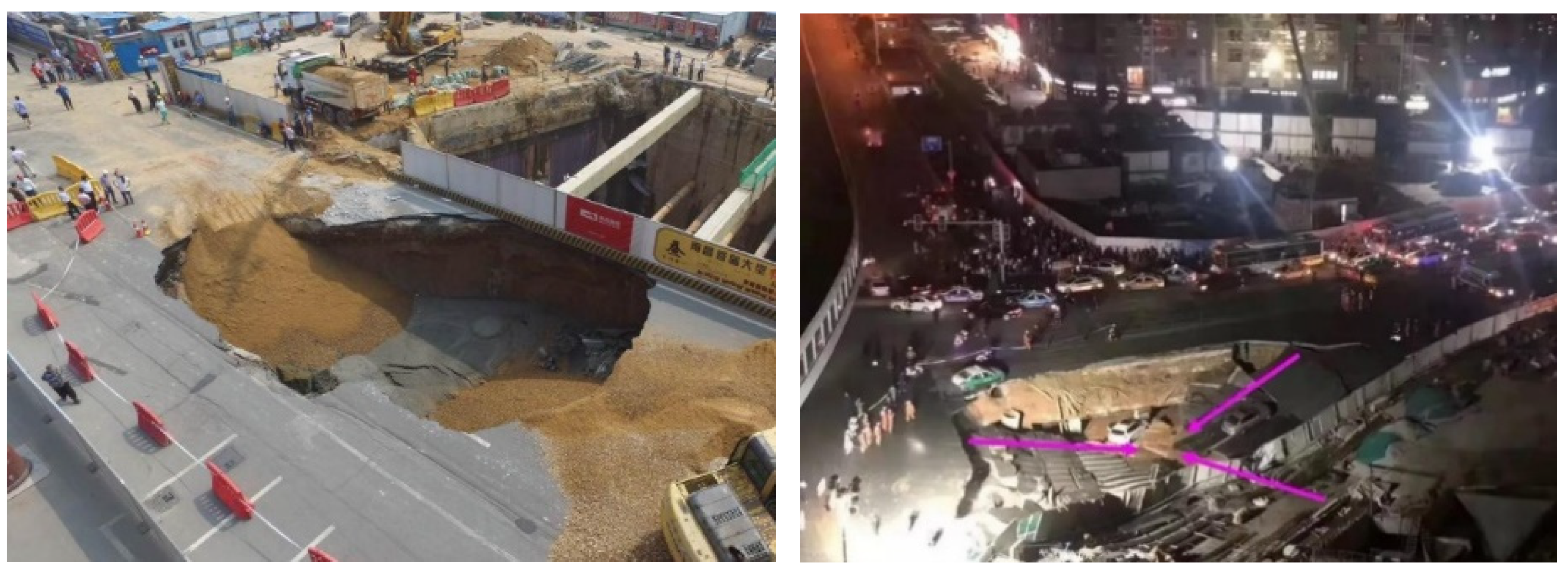
Figure 1). The urgency of addressing these challenges is underscored by increasing urbanization. However, existing design methodologies often inadequately account for defect-induced instability mechanisms, relying on simplified homogeneous models. This gap has prompted researchers to investigate composite strata behavior through experimental and numerical approaches, aiming to refine risk assessment frameworks and mitigation strategies.
Experimental investigations have been pivotal in elucidating failure mechanisms of subway tunnels in composite strata. Physical model tests, scaled to replicate field conditions, enable researchers to observe stress redistribution, deformation patterns, and progressive collapse under controlled scenarios. For example, Yan et al. [
3] investigated a catastrophic collapse during subway excavation in Qingdao, China, using centrifuge tests to simulate the groundwater-induced softening of sandy cobble layers. They identified a critical threshold of pore pressure beyond which seepage erosion triggered rapid cavity formation and tunnel face instability. Advanced monitoring techniques, such as distributed fiber optic sensing (DFOS) and 3D digital image correlation (DIC), have enhanced experimental precision. Li et al. [
6] employed DFOS to track strain localization in tunnel linings under asymmetric loading, demonstrating that defect clusters near the tunnel crown amplified bending moments by up to 40%. Meanwhile, Wei et al. [
7] utilized DIC to quantify crack propagation in scaled tunnel models, correlating defect density with collapse energy thresholds. These studies collectively highlight the sensitivity of composite strata to defect distribution and hydrological conditions, underscoring the need for defect-specific reinforcement strategies.
Defects in composite strata significantly alter mechanical responses, necessitating targeted experimental studies [
4,
5]. Cavities and fractures, whether pre-existing or induced by excavation, disrupt stress arching and reduce load-bearing capacity. Physical model tests by Carranza-Torres and Reich [
8] demonstrated that circular cavities in cohesive soil–rock interfaces reduced tunnel face stability by 25–30%, with failure modes transitioning from shear-dominated to tensile-dominated as cavity size increased. Similarly, Senent and Jimenez [
9] designed a series of trapdoor tests to simulate partial collapses in layered strata, showing that defect clustering within 1.5 times the tunnel diameter increased surface settlement by 150%. Di et al. [
10] conducted seepage experiments on sandy cobble strata, revealing that high groundwater flow rates (exceeding 0.1 m/s) eroded defect boundaries, forming preferential seepage channels that accelerated pore pressure dissipation. Their results aligned with field observations from the Guangzhou Metro, where water-rich fractured zones required grouting pressures 20% higher than theoretical predictions to stabilize tunnel faces. Additionally, Huang et al. [
11] developed a fluid–solid coupling apparatus to simulate shield tunneling under high water pressure, identifying a nonlinear relationship between defect orientation and seepage force magnitude. Vertically aligned defects amplified hydraulic gradients, while horizontal defects promoted lateral soil loosening. Conversely, Rostami [
12] analyzed crushed zones around disk cutters in mixed-face tunneling, demonstrating that rock proportion exceeding 70% suppressed defect propagation but increased cutter wear. Li et al. [
13] conducted a series of experiments to investigate the failure mechanisms of rock blocks with combined flaws under coupled static and dynamic loads. Chen et al. [
14] investigated failure mechanisms of cavity-induced railway tunnel collapse in defect phyllite strata, proposing steel arch replacement and grouting reinforcement to enhance rock lining structural integrity. Shiau et al. [
15] investigated the ground stability of ellipsoidal cavities due to pipeline defects using advanced finite element limit analysis with adaptive meshing in an axisymmetric condition. Zhou et al. [
16] investigated the coupling defect effect of elliptical cavities and cracks on tunnel dynamic stability and failure modes through AUTODYN-based numerical simulations and modified drop-hammer impact tests. It can be seen that inner defects can disrupt the stress state and reduce the load-bearing capacity of strata.
Subway tunnels excavated in composite strata face great challenges due to the inherent heterogeneity. Research has also been performed in this regard. For example, Zhang et al. [
1] investigated the collapse mechanism of subway tunnels in soil–sand–rock composite strata through physical model tests. They highlighted the impact of stratum heterogeneity on tunnel stability and identified key failure modes under different loading conditions. Liu et al. [
2] conducted model tests to investigate the progressive collapse mechanism of shallow subway tunnels in soft upper and hard lower composite strata. They revealed that the collapse process is influenced by the interaction between the soft and hard layers, with stress redistribution playing a critical role in the failure pattern. The findings emphasized the role of stress anisotropy in controlling the failure patterns and collapse progression. It can be concluded that the composite strata significantly influences tunnel stability and collapse mechanisms. These studies provide valuable insights into the collapse mechanisms of tunnels in composite strata, highlighting the importance of considering stratum heterogeneity in tunnel risk assessment.
It can be found that both ground defects and non-homogeneous characteristics of composite strata can affect the stability of tunneling projects. However, most of the existing studies on ground defects are focused on a unique stratum, and the few studies on composite strata have failed to systematically reveal the effects of different locations of cavities on tunnel stability. Existing experimental studies have significantly advanced the understanding of tunnel failures in composite strata, yet critical gaps persist. Therefore, the collapse mechanism of soil–rock composite strata influenced by the inner cavity should be figured out. To address these limitations, this study adopts indoor experiments to study the instability process of a subway tunnel in soil–rock composite strata influenced by inner cavities. A total of six groups of tests were designed based on the location of the cavity and the distance of the cavity from the tunnel. High-resolution monitoring techniques are employed to capture the real-time deformation and failure process of strata. Finally, a predictive framework for the instability risk assessment is used and we propose targeted reinforcement measures, such as defect-specific grouting protocols.
2. Model Test Design
2.1. Similarity Theory of Model Test
Similarity theory is a doctrine used to study the principle of similar phenomena in engineering, and it is the basis for model test research, which can satisfy the similarity theory to make the model test and the actual phenomenon have the same physical parameters and physical relationships. According to the results of previous research, the sufficient conditions for similarity of physical phenomena can be summed up in the following three theorems:
- (1)
First theorem of similarity
This theorem was first proposed by Newton in 1688, and then a rigorous proof was given by the French scholar Beltrán in 1848. The first theorem of similarity can be expressed as follows: if the phenomena are similar and the single-valued conditions are the same, then the similarity index is equal to 1 or the similarity criteria are equal, and the single-valued conditions include geometric conditions, physical conditions, boundary conditions, and initial conditions.
- (2)
Second theorem of similarity
This theorem was proposed and derived by the Russian scholar Fetelman in 1911. The second theorem of similarity can be expressed as follows: if the phenomena are similar, then the physical equations describing the similar phenomena can be transformed into a functional relationship between the similarity criteria, and the functional relationship between the similarity criteria is the same.
- (3)
Third theorem of similarity
This theorem was proposed by the former Soviet scholar Kirpichov in 1930. The third theorem of similarity can be expressed as follows: where the same phenomena are similar if the single-valued conditions are similar and the similarity criterion consisting of such single-valued conditions is numerically equal, then these phenomena must be similar.
Similarity theory dictates that the equilibrium equations, geometric compatibility conditions, constitutive relations, stress boundaries, and displacement boundaries must satisfy strict congruence between the prototype and scaled models [
9,
10,
11]. The similarity ratios of the model test have the following relation:
where
Cσ,
CL,
Cγ,
Cδ,
Cε, and
CE represent the similarity ratio of stress, geometry, density, displacement, strain, and elastic modulus, respectively. Taking into account the basic conditions of the model test and the various influencing factors in the test, the similarity of the model test selected for the model test of soil–rock composite strata containing voids in this paper is as follows: the similarity ratio of geometric
Cl = 20, similarity ratio of stress
Cσ = 20, similarity ratio of elastic modulus
CE = 20, similarity ratio of displacement
Cu = 20 and similarity ratio of cohesion
Cc = 20; however, the similarity ratio of gravity
Cγ = 1, similarity ratio of strain
Cε = 1, similarity ratio of Poisson’s ratio
Cμ = 1, and similarity ratio of friction angle
Cφ = 1.
2.2. Model Test Setup
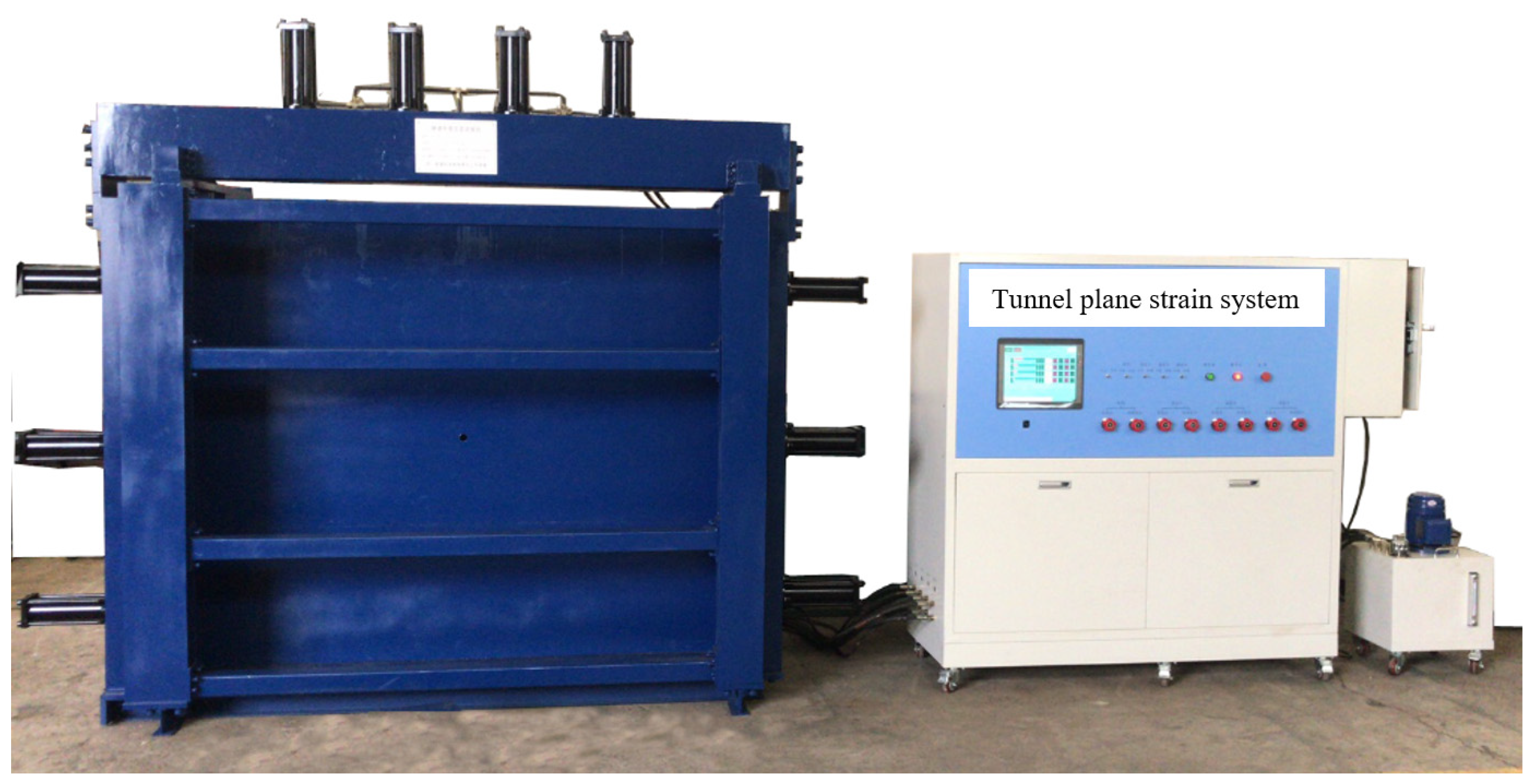
The model test device mainly includes three parts, a model test box, loading system, and control system, as shown in
Figure 2. This test uses an airbag unloading system for tunnel excavation simulation and a non-contact video monitoring system for monitoring changes at various points within the surrounding rock and ground settlement. The size of the model test box is 2.0 m × 0.3 m × 1.8 m (length × width × height). To easily observe the changes in the stratum inside the box during the loading process, a plexiglass panel that can withstand a certain amount of pressure is used on the front of the box, with a 300 mm diameter hole in the center of the panel, which is the same as the diameter of the tunnel model. To reduce the boundary effect, the center of the circular hole was located 60 cm away from the lower boundary of the front panel and 85 cm away from the left and right boundaries. To increase the rigidity of the front and back of the box, columns are added to the front and back panels of the box. The columns are connected to the base of the box with screws and connected to the top beam track plate so that the overall structure of the box is strengthened. To add soil material, we disengage the connecting plate of the top beam of the box. A roller mounted on the top beam can be pushed to the rear of the test box to complete the filling. The loading system consists of servo-hydraulic cylinder steady pressure and steady flow loading. The automatic control system consists of PLC control and a human–machine interface touchscreen. To simulate the real tunnel excavation process, a non-elastic cylindrical airbag is buried at the tunnel location of the model box, which is connected to the air compressor through a pressure valve, and the pressure value inside the airbag is controlled through the pressure valve. During the test, the pressure is released step by step through a pressure valve to simulate the tunnel excavation process. After the deformation of the stratum is stabilized, the airbag is pulled out. A non-contact video monitoring system is used to monitor and record the changes in the internal points of the surrounding rock and the settlement of the strata.
2.3. Similarity Materials
To highlight the difference between soil and rock layers, the soil layer is considered as Class VI surrounding rock, and the rock layer is considered as Class IV surrounding rock. According to the 1:20 similarity ratio of the model test, the parameters of the corresponding materials were converted. A corresponding model with similar materials to the prototype was prepared. The conversion relationship between the physical and mechanical indexes of the prototype and the model of the two types of surrounding rock is shown in
Table 1.
In addition to the selection of similar materials to meet the basic physical and mechanical properties of the test indicators, we generally need to agree on the following principles: similar materials should have similar physical and mechanical properties with the prototype material; that is, the material should be uniform and isotropic. Changing the ratio of the material can make its physical and mechanical properties meet the test requirements and can be deployed to different physical and mechanical parameters of the model material. The performance of the molded material has a certain amount of stability and is not affected by external conditions (temperature, humidity, etc.) and less affected by the outside world. The material itself is reasonably priced, and the system is easy to transport and process for production.
Gypsum-based materials, sand/paraffin/resin, and barite powder/bentonite blends are similar materials that are often used, and 3D-printed composites are currently more popular. However, all of the above materials have advantages and limitations and need to be employed according to the research objectives and requirements. Considering the properties, ease of access, and economics of similar materials, barite, quartz sand, and petroleum jelly were selected in conjunction with established research studies. Despite the limitations mentioned above, model tests are a very common research tool today. They have significant advantages in representing the real mechanical state and failure process of the strata. In this paper, the material mixed with quartz sand and barite as the aggregate and petroleum jelly as the binder is chosen as the model test material. This material can not only meet the above requirement but also has the characteristics of a short forming time, a high capacity of mixed material, and stable mechanical properties, and it is reusable. Combined with the previous research results, this paper adopts a similar material ratio of barite/quartz sand/petroleum jelly = 10:4.8:1 for class IV surrounding rock and barite/quartz sand/petroleum jelly = 8:5:0.6 for class VI surrounding rock. The physical and mechanical parameters of similar materials are shown in
Table 2.
2.4. Model Test Schemes
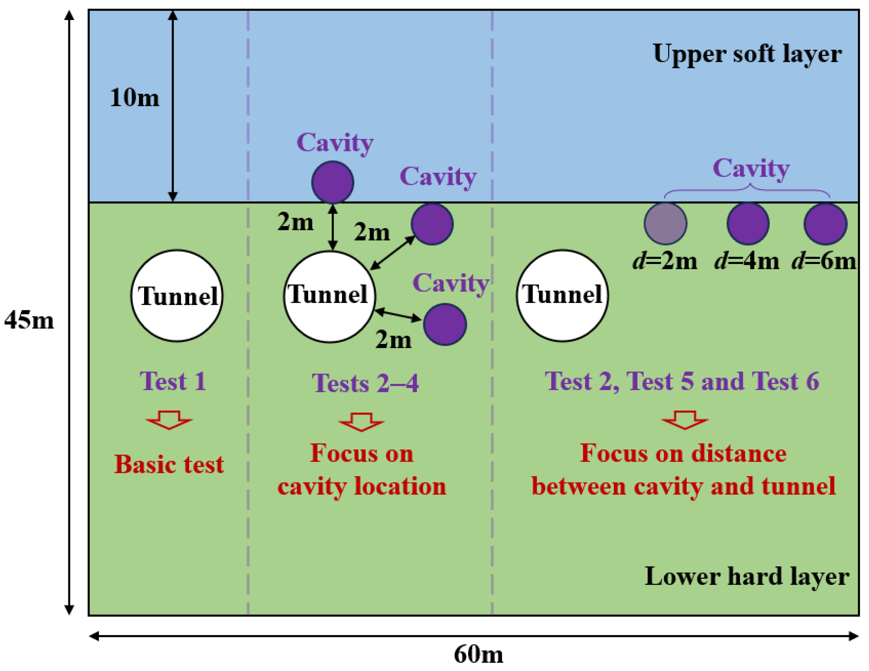
The test mainly investigates the stability of the ground during the excavation of tunnels through the ground with cavities. According to the relative position and distance between the cavity and the tunnel, a total of six tests were identified. Based on the geometric similarity ratio of 1:20, the tunnel diameter is determined to be 30 cm, and the tunnel depth is 60 cm. The rock-to-span ratio is 1:3, where the thickness of the upper soil layer is 50 cm. The diameter of the cavity is 10 cm. The cavities are designed to be located directly above the tunnel, diagonally above the tunnel, and at the foot of the tunnel. The distance between the cavity and the tunnel is designed to be 10 cm, 20 cm, and 30 cm. The specific test plan is shown in
Table 3, and a schematic diagram of the model test plan is presented in
Figure 3.
The scale of the model test is 1:20, the tunnel diameter is 30 cm, and the tunnel center is 100 cm away from the model boundary. Therefore, the influence of the boundary effect in this experiment is not significant. In addition, to further weaken the boundary effect, the bottom and both sides of the test box were filled with cushioning material with similar stiffness to the soil body. Moreover, this experiment is a staged application of load at the top of the model conducted to avoid the superposition of stress waves reflected at the boundary due to transient loading.
2.5. Model Test Procedure
The main procedure of the mode test is as follows:
- (1)
Material configuration process: Firstly, weigh the materials required for the test according to the decided ratio. Preheat the quartz sand and barite powder in the oven at 90–100 degrees Celsius, and melt the petroleum jelly by heating it in a water bath. After the preparation work has been carried out, mix and color the three test materials by manual and mechanical mixing.
- (2)
Material and tunnel model filling and cavity pre-embedding: Similar materials are filled in the test model stand. Control the height of the material pile and the weight of the filled material by manual tamping to control the density of the soil body. Obtain the strength of similar materials in line with the requirements of the model test. Fill the soil to the bottom of the tunnel model and the location of the cavity, pre-bury the tunnel airbag to the location of the tunnel model and pre-bury the airbag in the cavity. After the similar material is filled and compacted by applying static loads, deflate the airbags to form ground cavities and leave them to rest for one hour.
- (3)
Tunnel airbag unloading: The airbag is gradually unloaded by controlling the pressure value to simulate the stress relief during tunnel excavation. After unloading the tunnel airbag completely, the airbag is pulled out to simulate tunnel excavation. Although the airbag may not replicate natural void geometries, it has been proven that the airbag is a simple and effective method to simulate cavities. This simplified method can also better represent the changes in the strata stability caused by cavities [
17,
18,
19].
- (4)
Application of upper load: After the deformation of the stratum is stabilized, the upper load is applied by the test loading system step by step until the deformation of the stratum is destroyed.
- (5)
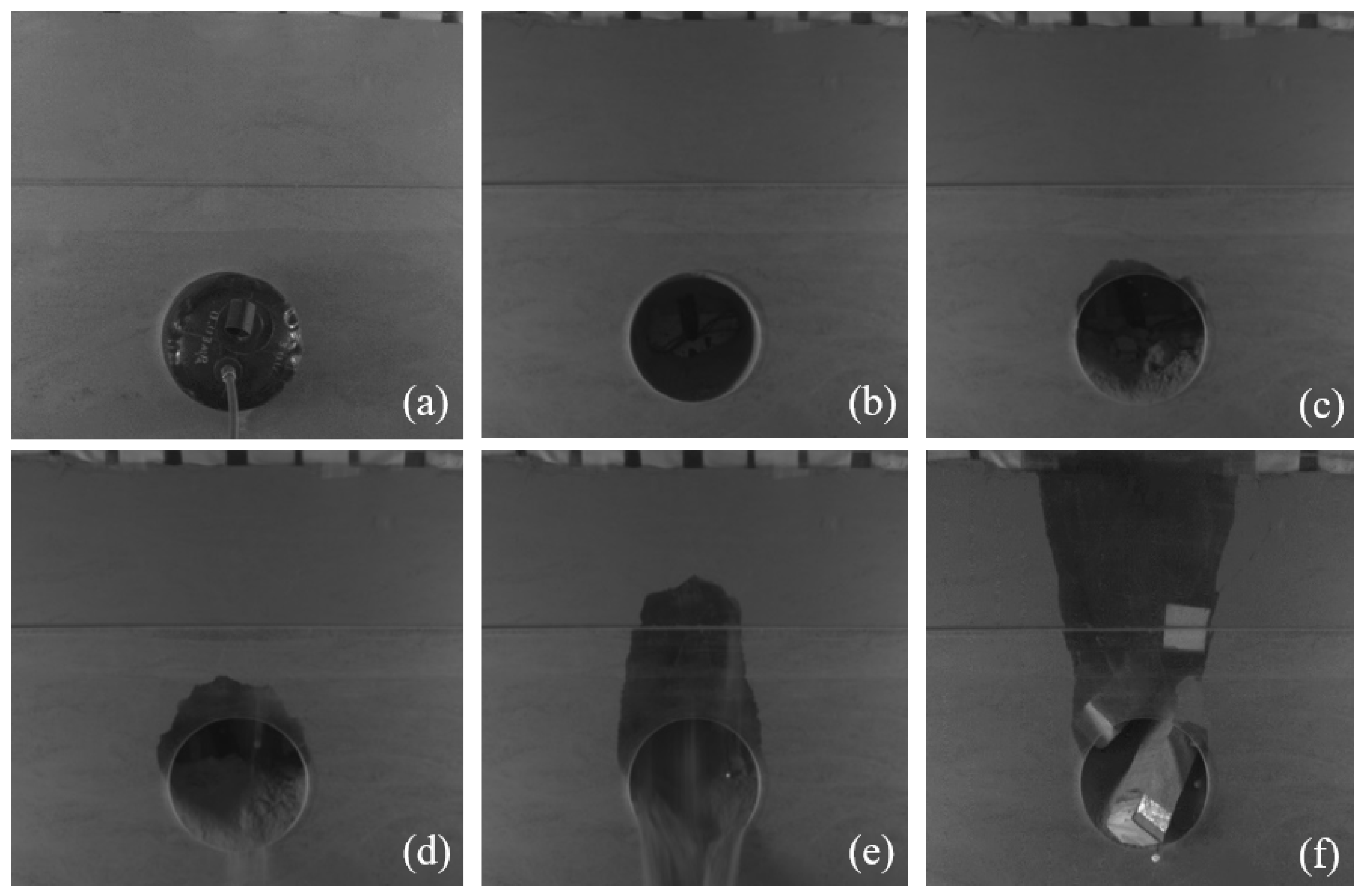
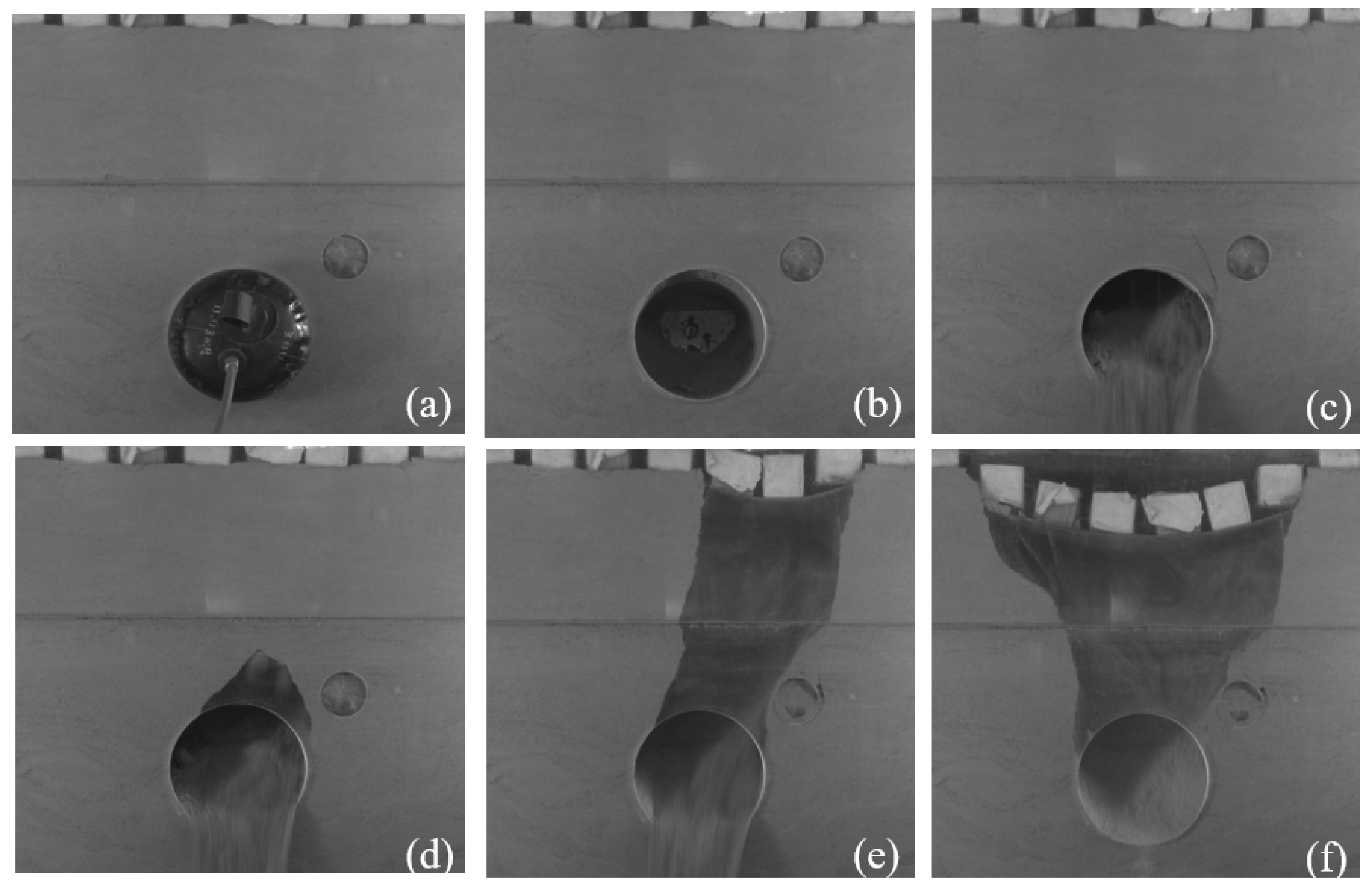
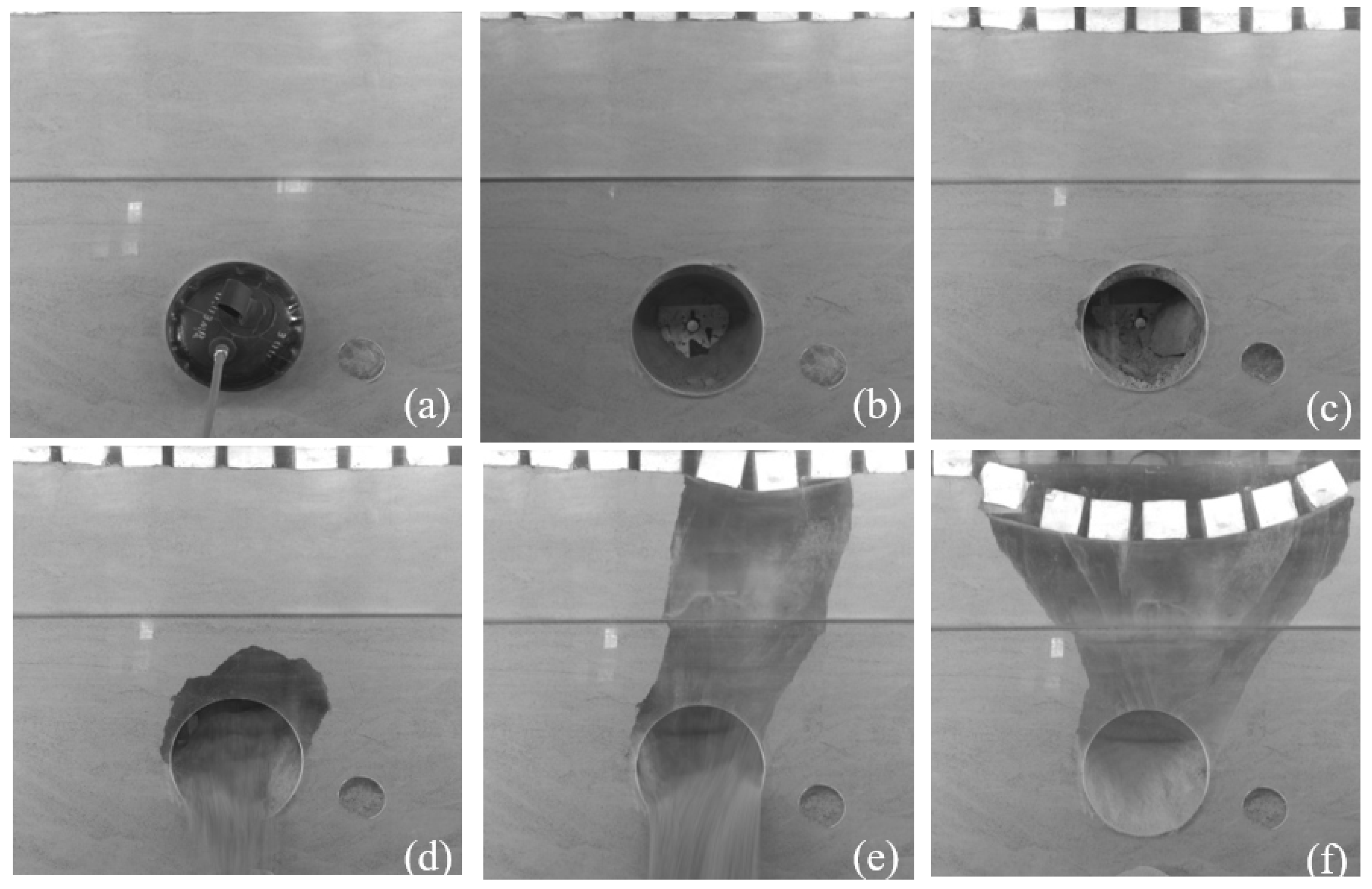
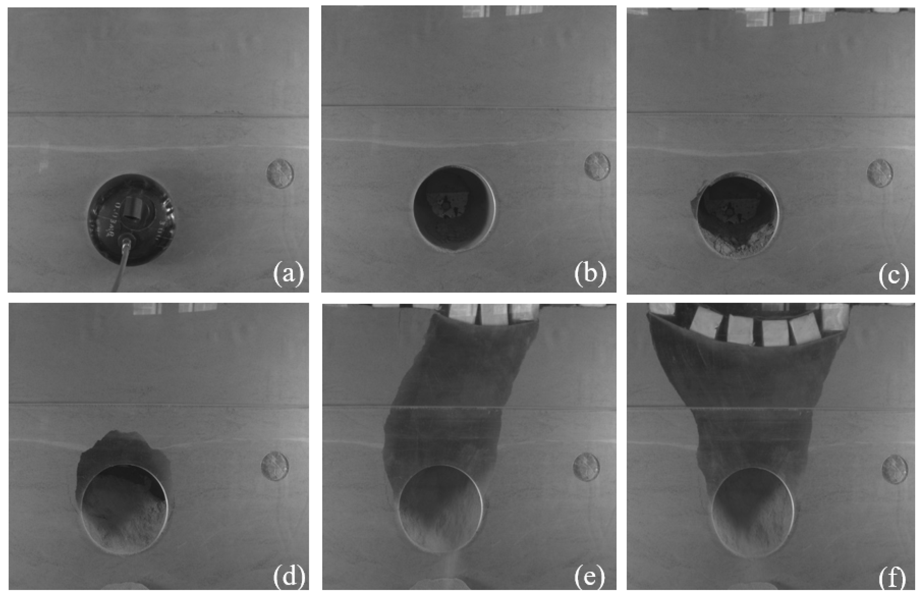
Data acquisition: A non-contact video monitoring system is used to record the results of surface settlement, as well as the damage pattern of the surrounding rock during the deformation and destruction of the strata after the application of upper loads.
4. Discussion
The presence of cavities can affect the stability of the strata during tunneling.
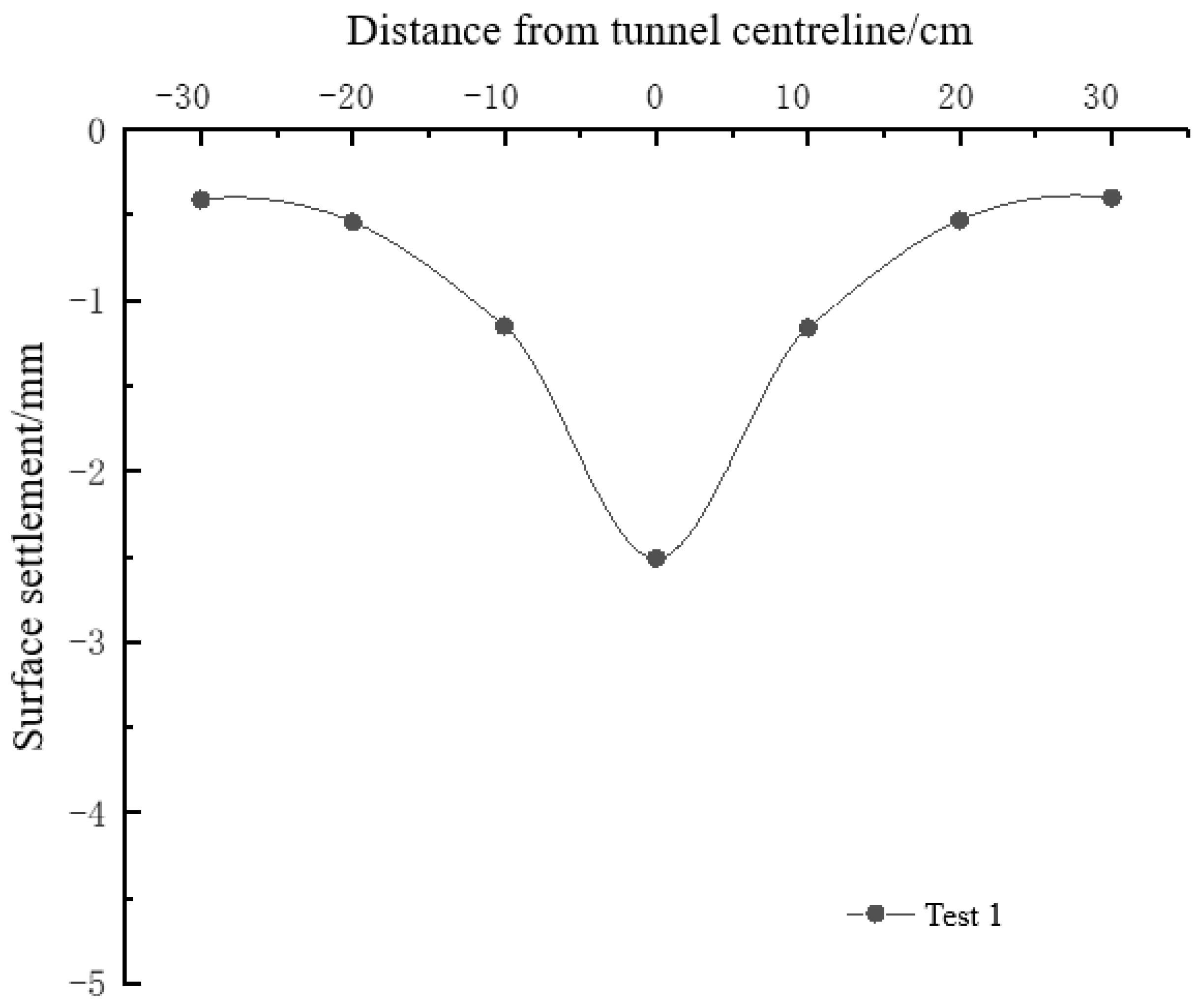
Figure 14 shows the maximum surface settlement excavation induced and ultimate loads for strata influenced by cavity location. It can be seen that when there is no cavity, the maximum deformation of the ground surface caused by tunnel excavation is 2.51 mm and the ultimate bearing capacity of the strata is 10 kPa. The maximum deformation of the ground surface caused by tunnel excavation in Case 2, Case 3, and Case 4 are 3.14 mm, 3.42 mm, and 3.64 mm, respectively. The results showed that the existence of a cavity would increase the ground deformation, and the cavity at different locations has an effect on the ground deformation. In addition, the loads of strata failure in Case 2, Case 3, and Case 4 are 6 kPa, 4 kPa, and 4 kPa, respectively. It is seen that the existence of cavities significantly reduces the stability of the strata, and the failure occurs in advance under the external loads.
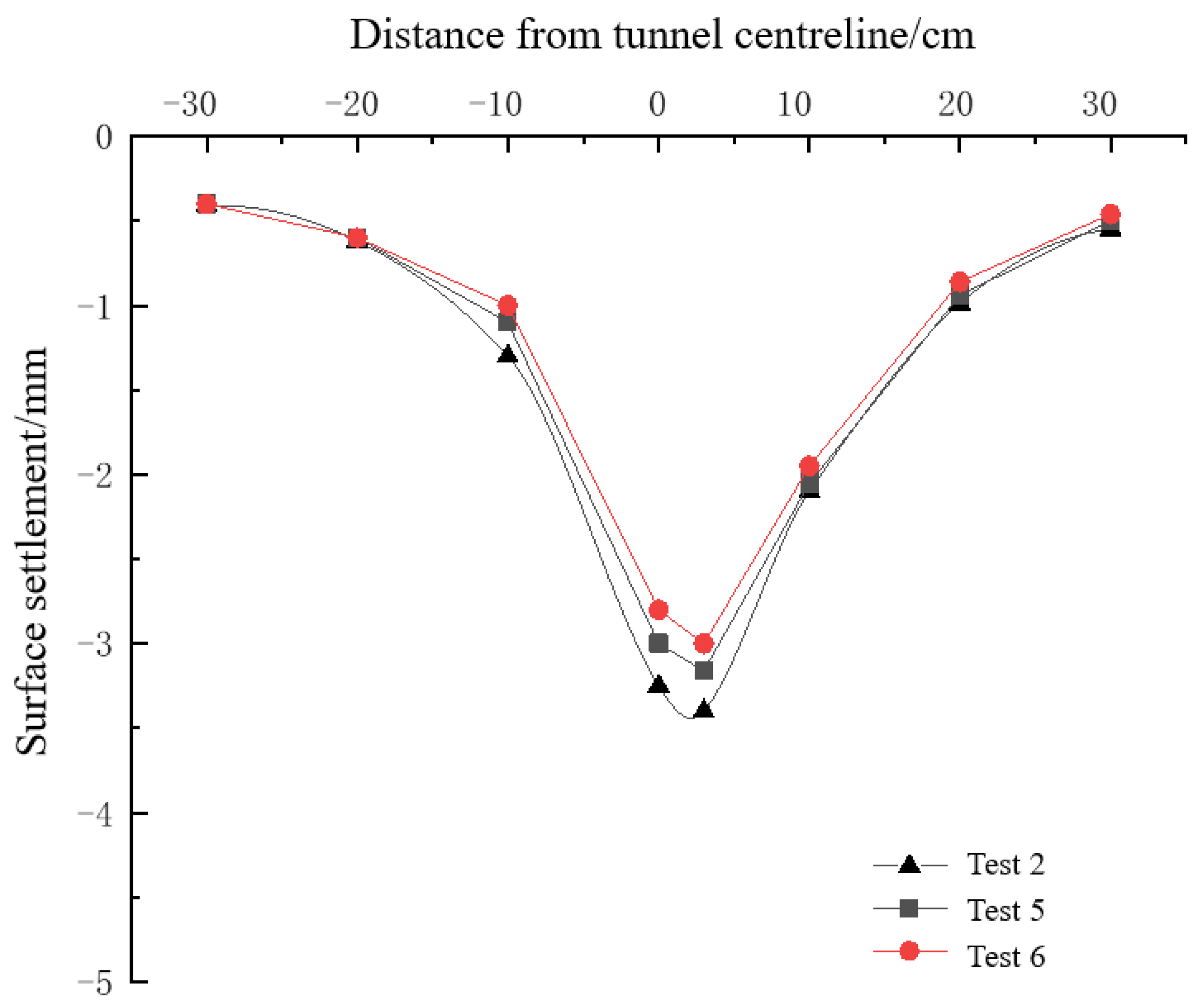
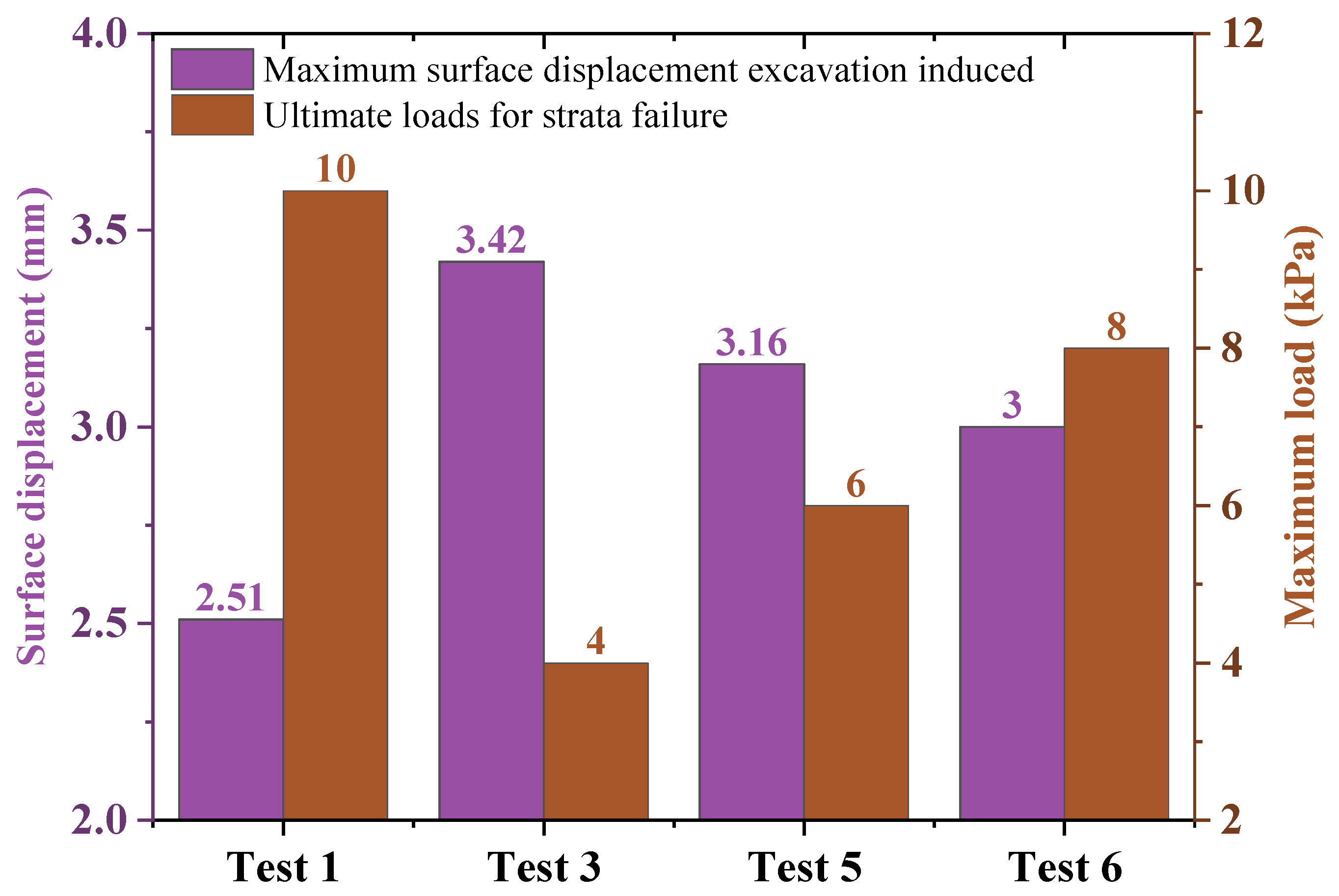
In addition, the effect of the distance between the cavity and tunnel on the strata stability is investigated. The deformation and bearing capacity of the strata for various distances between the cavity and the strata are given in
Figure 15. When the distance between the tunnel and the cavity is 2 m, 4 m, and 6 m, respectively, the maximum deformation of the ground surface is 3.42 mm, 3.16 mm, and 3 mm, and the bearing capacity is 4 kPa, 6 kPa, and 8 kPa, respectively. With the increase in the distance between the tunnel and the cavity, the maximum surface settlement value decreases accordingly, and the intensity of the strata failure is also reduced accordingly, which indicates that the further the tunnel excavation is away from the cavity of the ground layer, the safer it is.
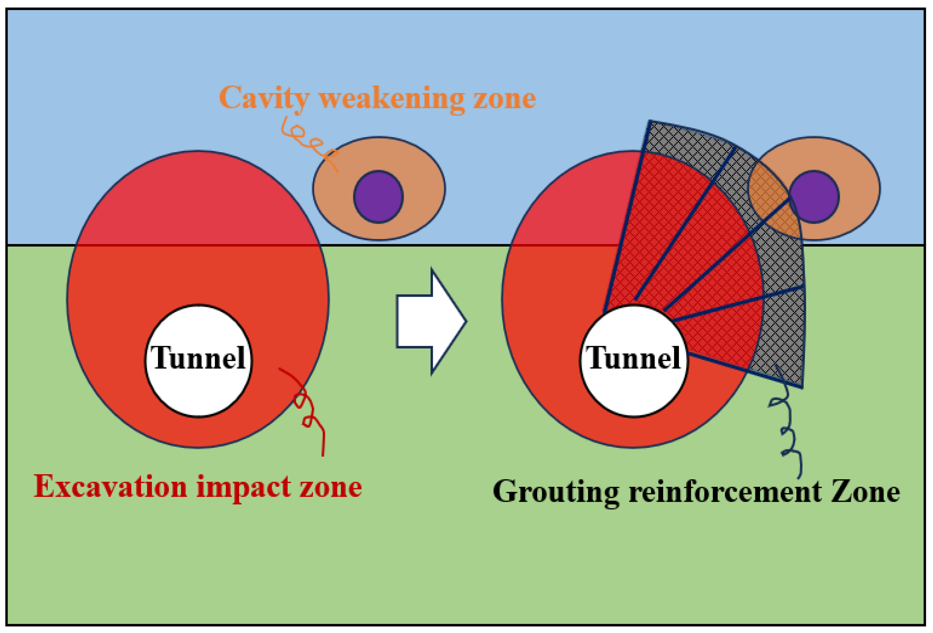
It can be seen that the existence of ground cavities greatly affects the safety of tunnel construction. When the tunnel excavation impact zone is connected with the cavity weakening zone, the probability and range of stratum collapse will increase, which is the reason why many accidents happen nowadays. Therefore, to avoid similar accidents, it is necessary to take advanced measures for reinforcement treatment. One solution is given in
Figure 16, which is to reinforce the strata by grouting around the tunnel. This grouting reinforcement must extend beyond the zone affected by the tunnel excavation to reduce the probability of interaction between the cavity and the tunnel, thus improving the safety of the strata. The following commonly used common grouting materials include cement slurry, cement–water–glass bi-liquid slurry, chemical slurry, and ultra-fine cement slurry. The material chosen needs to be decided according to the strata type. The grouting pressure is usually 0.5–3.0 MPa, depending on the formation conditions and the depth of the grouting. The initial grouting pressure is low and gradually increases to the design pressure. The effectiveness and reasonableness of the grouting material and grouting pressure can be validated by indoor tests and field tests. Therefore, through a reasonable selection of materials and processes, grouting reinforcement can effectively improve the stability and safety of subway tunnels.
Some limitations of this paper need to be stated. First, groundwater is an extremely dangerous factor for underground engineering. Groundwater causes seepage-coupled damage to formations by changing effective stresses, permeability, and mechanical properties. In particular, changes in pore water pressure lead to a reduction in the effective stress of the composite strata [
20]. Future modifications can be made based on this test setup, aiming to study the failure mechanism of composite strata containing voids under the action of groundwater. In addition, cavities in strata are commonly present and there is uncertainty about their location, size, and number. Thus, it is recommended to systematically reveal the mechanism of the influence of the location, size, and number of cavities on the strata stability. In addition, the application of numerical methods such as discrete elements can further reveal the collapse mechanism of complex strata in the future.


