

Elastic Body Spring Method (EBSM) for the Stability Analysis of the Global Vipassana Pagoda in Mumbai, India


Abstract
1. Introduction
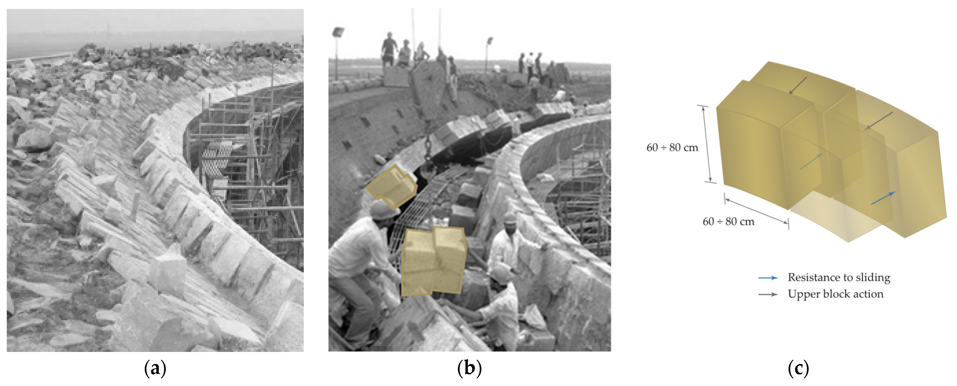
2. The Global Vipassana Pagoda
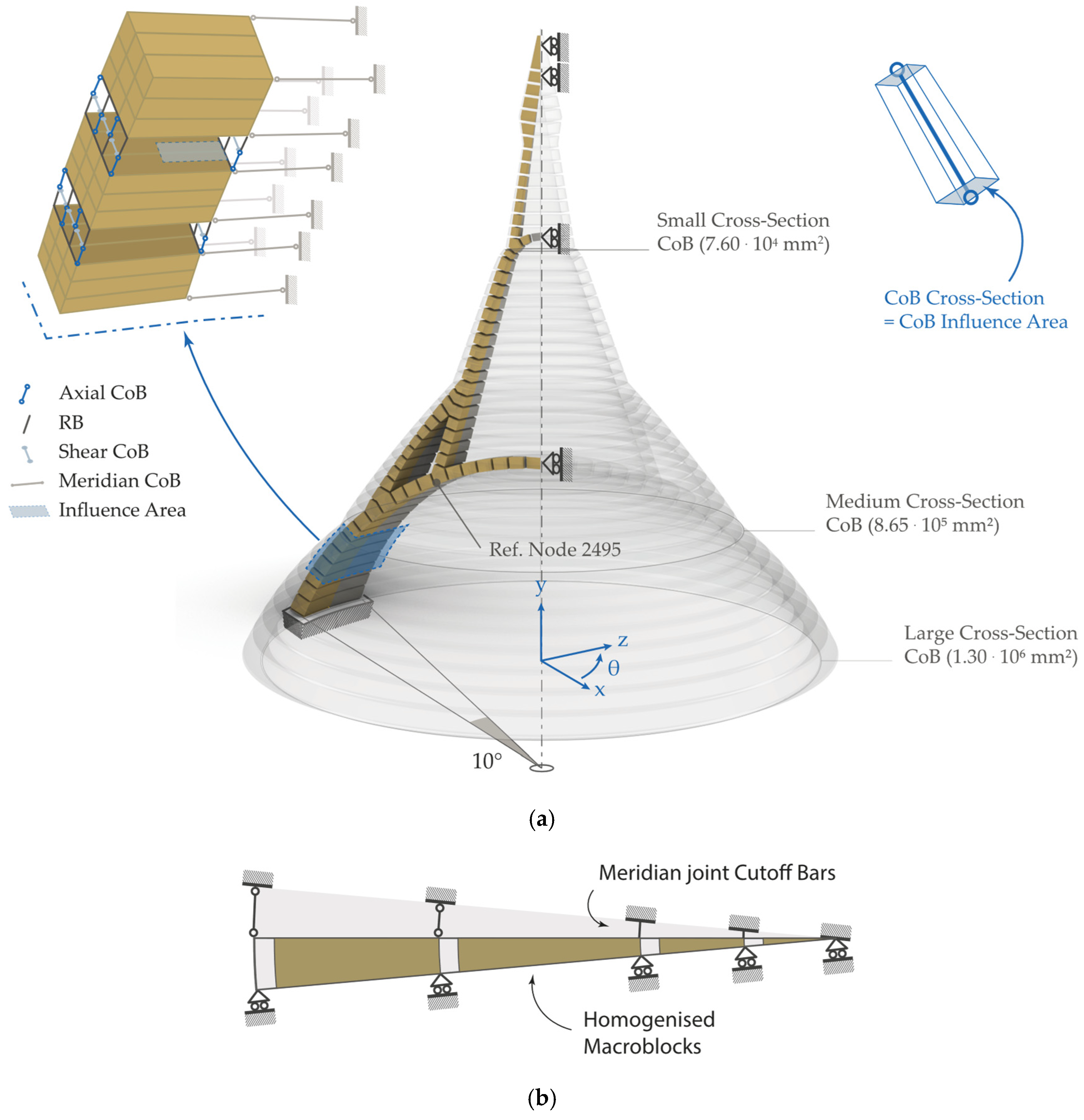
2.1. Structural Modelling
2.1.1. 3D Case
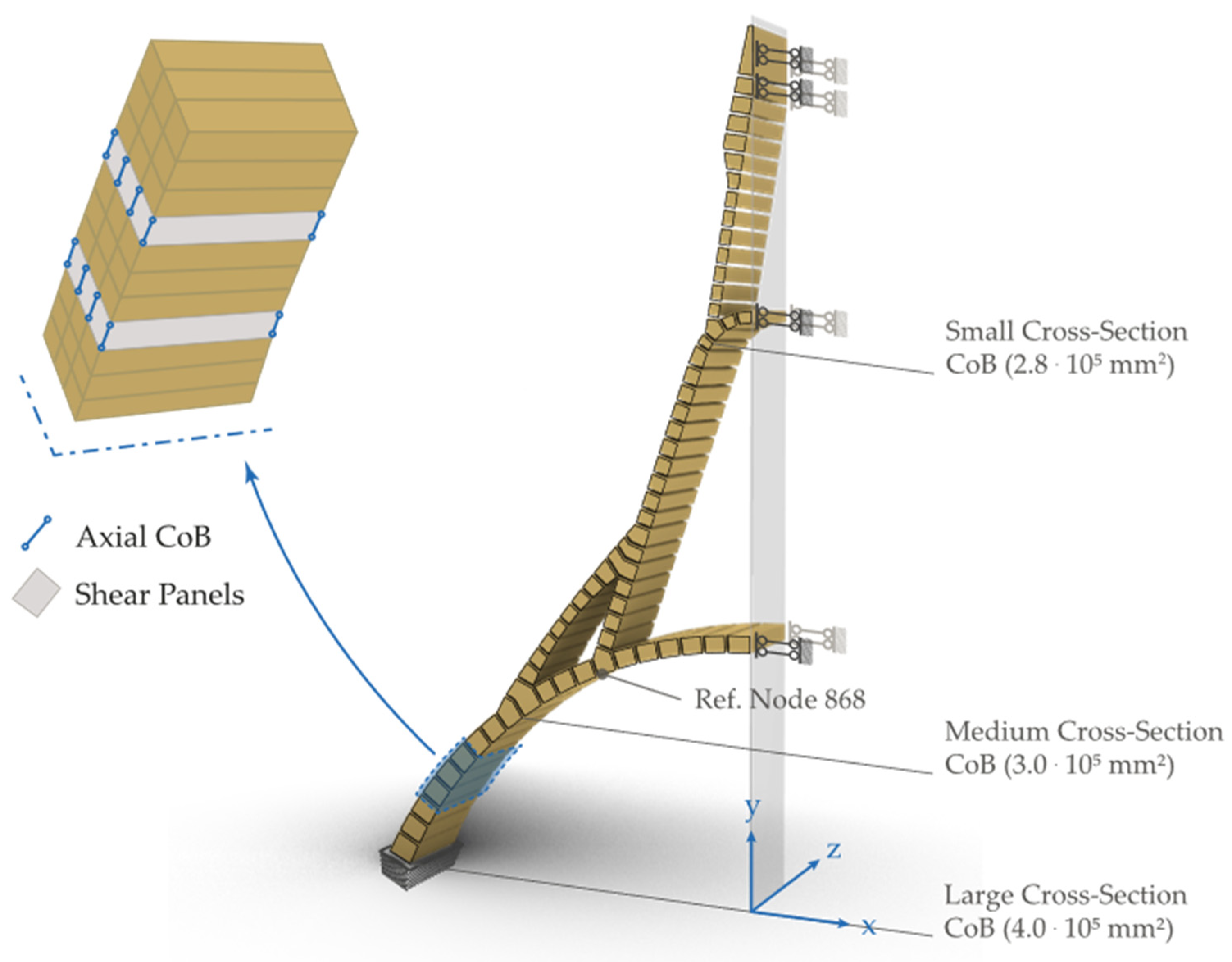
- Tie the slice in the hoop direction, as happens in a real domical structure (meridian cutoff bars, CoBs);
- Consider the mutual action of a fuse against the axisymmetric one (rollers);
- Assume the impossibility of sliding at the springing and fixed joints.
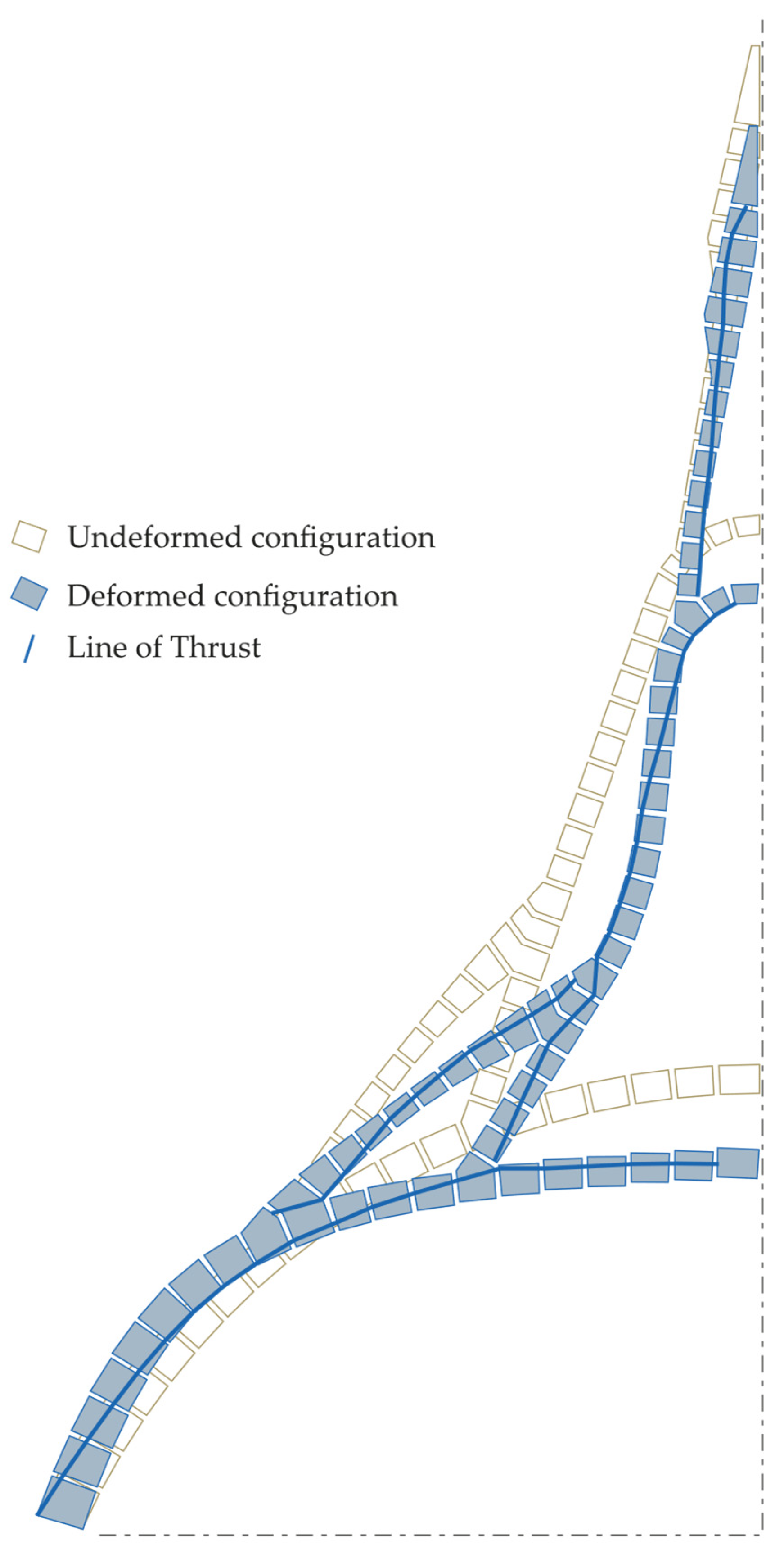
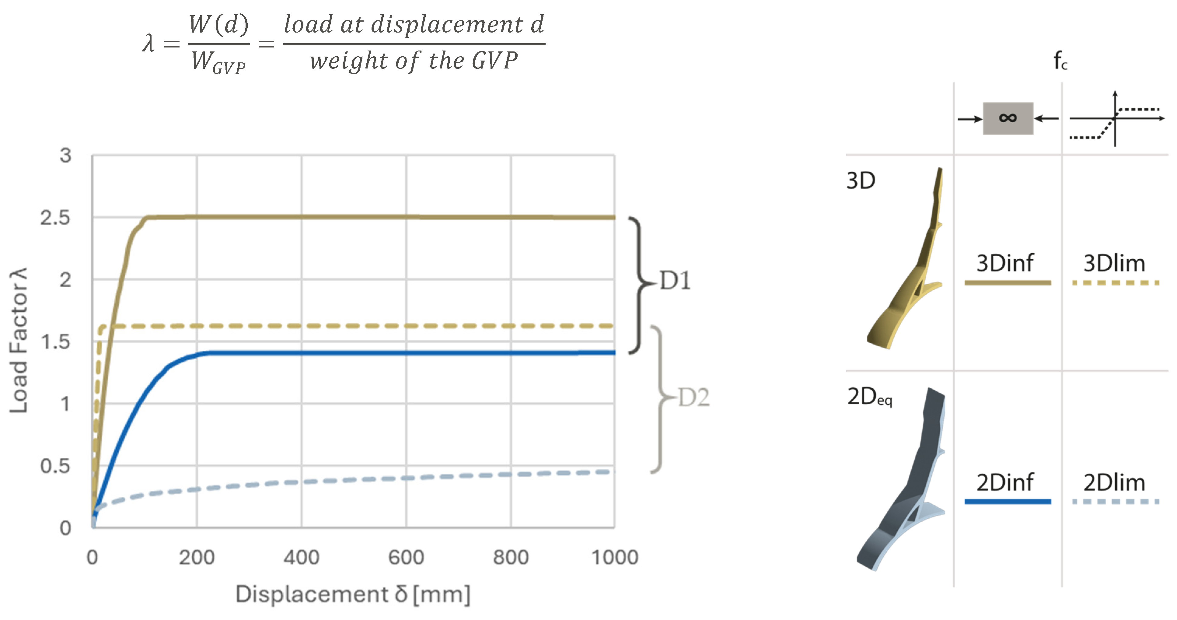
2.1.2. 3D Case: NLSA Results

2.1.3. 2D Case or the Equivalent Vault
- The leaning against the other half for symmetry conditions and the constraint for rotation is set with a double pendulum;
- The theoretical impossibility of sliding at the springing is represented by fixed nodes.
2.1.4. 2D Case: NLSA Results
2.2. Discussion
3. Conclusions and Open Issues
Author Contributions
Funding
Data Availability Statement
Acknowledgments
Conflicts of Interest
References
- Milani, E.; Milani, G.; Tralli, A. Limit Analysis of Masonry Vaults by Means of Curved Shell Finite Elements and Homogenization. Int. J. Solids Struct. 2008, 45, 5258–5288. [Google Scholar] [CrossRef]
- Grillanda, N.; Chiozzi, A.; Milani, G.; Tralli, A. Collapse Behavior of Masonry Domes under Seismic Loads: An Adaptive NURBS Kinematic Limit Analysis Approach. Eng. Struct. 2019, 200, 109517. [Google Scholar] [CrossRef]
- Dell’Endice, A.; DeJong, M.J.; Van Mele, T.; Block, P. Structural Analysis of Unreinforced Masonry Spiral Staircases Using Discrete Element Modelling. Structures 2022, 46, 214–232. [Google Scholar] [CrossRef]
- Işık, E.; Harirchian, E.; Arkan, E.; Avcil, F.; Günay, M. Structural Analysis of Five Historical Minarets in Bitlis (Turkey). Buildings 2022, 12, 159. [Google Scholar] [CrossRef]
- Milani, G.; Esquivel, Y.W.; Lourenço, P.B.; Riveiro, B.; Oliveira, D.V. Characterization of the Response of Quasi-Periodic Masonry: Geometrical Investigation, Homogenization and Application to the Guimarães Castle, Portugal. Eng. Struct. 2013, 56, 621–641. [Google Scholar] [CrossRef]
- Bilgin, H.; Ramadani, F. Numerical Study to Assess the Structural Behavior of the Bajrakli Mosque (Western Kosovo). Adv. Civ. Eng. 2021, 2021, 1–17. [Google Scholar] [CrossRef]
- Durand-Claye, A. Vérification de La Stabilité Des Voûtes et Des Arcs: Applications Aux Voûtes Sphériques. Ann. Ponts Chaussées 1880, 19, 416–440. [Google Scholar]
- Sharbaf, A.; Bemanian, M.; Daneshjoo, K.; Shakib, H. Masonry Dome Behavior under Gravity Loads Based on the Support Condition by Considering Variable Curves and Thicknesses. Buildings 2021, 11, 241. [Google Scholar] [CrossRef]
- O’Dwyer, D. Funicular Analysis of Masonry Vaults. Comput. Struct. 1999, 73, 187–197. [Google Scholar] [CrossRef]
- Block, P. Thrust Network Analysis. Ph.D. Thesis, Massachusetts Institute of Technology, Cambridge, MA, USA, 2009. [Google Scholar]
- Cavicchi, A.; Gambarotta, L. Two-Dimensional Finite Element Upper Bound Limit Analysis of Masonry Bridges. Comput. Struct. 2006, 84, 2316–2328. [Google Scholar] [CrossRef]
- Milani, G. Upper Bound Sequential Linear Programming Mesh Adaptation Scheme for Collapse Analysis of Masonry Vaults. Adv. Eng. Softw. 2015, 79, 91–110. [Google Scholar] [CrossRef]
- Scacco, J.; Grillanda, N.; Milani, G.; Lourenço, P.B. Novel Non-Linear Static Numerical Model for Curved Masonry Structures Based on a Combined Adaptive Limit Analysis and Discrete FE Computations. Int. J. Solids Struct. 2022, 236–237, 111265. [Google Scholar] [CrossRef]
- Girardi, M.; Padovani, C.; Pellegrini, D. The NOSA-ITACA Code for the Safety Assessment of Ancient Constructions: A Case Study in Livorno. Adv. Eng. Softw. 2015, 89, 64–76. [Google Scholar] [CrossRef]
- Barsi, F.; Barsotti, R.; Bennati, S. Admissible Shell Internal Forces and Safety Assessment of Masonry Domes. Int. J. Solids Struct. 2023, 264, 112082. [Google Scholar] [CrossRef]
- Nodargi, N.A.; Bisegna, P. Collapse Capacity of Masonry Domes under Horizontal Loads: A Static Limit Analysis Approach. Int. J. Mech. Sci. 2021, 212, 106827. [Google Scholar] [CrossRef]
- Scacco, J.; Milani, G.; Lourenço, P.B. Automatic Mesh Generator for the Non-Linear Homogenized Analysis of Double Curvature Masonry Structures. Adv. Eng. Softw. 2020, 150, 102919. [Google Scholar] [CrossRef]
- Milani, G.; Valente, M.; Alessandri, C. The Narthex of the Church of the Nativity in Bethlehem: A Non-Linear Finite Element Approach to Predict the Structural Damage. Comput. Struct. 2018, 207, 3–18. [Google Scholar] [CrossRef]
- Öztürk, Ş.; Bayraktar, A.; Hökelekli, E.; Ashour, A. Nonlinear Structural Performance of a Historical Brick Masonry Inverted Dome. Int. J. Archit. Herit. 2020, 14, 1161–1179. [Google Scholar] [CrossRef]
- Jasieńko, J.; Raszczuk, K.; Kleszcz, K.; Frąckiewicz, P. Numerical Analysis of Historical Masonry Domes: A Study of St. Peter’s Basilica Dome. Structures 2021, 31, 80–86. [Google Scholar] [CrossRef]
- Gandolfi, A.; Pingaro, N.; Milani, G. Simple Non-Linear Numerical Modelling for Unreinforced and FRP-Reinforced Masonry Domes. Buildings 2024, 14, 166. [Google Scholar] [CrossRef]
- Lourenço, P.B. Construction Materials: Their Nature and Behaviour. Part VIII, 5th ed.; Domone, P., Soutsos, M., Eds.; CRC Press/Taylor & Francis Group: Boca Raton, FL, USA, 2017; ISBN 9781315164595. [Google Scholar]
- Page, A.W. The Biaxial Compressive Strength of Brick Masonry. Proc. Inst. Civ. Eng. (Lond.) Part 1—Des. Constr. 1981, 71, 893–906. [Google Scholar] [CrossRef]
- Xu, C.; Xiangli, C.; Bin, L. Modeling of Influence of Heterogeneity on Mechanical Performance of Unreinforced Masonry Shear Walls. Constr. Build. Mater. 2012, 26, 90–95. [Google Scholar] [CrossRef]
- Heyman, J. The Stone Skeleton. Int. J. Solids Struct. 1966, 2, 249–279. [Google Scholar] [CrossRef]
- Heyman, J. The Safety of Masonry Arches. Int. J. Mech. Sci. 1969, 11, 363–385. [Google Scholar] [CrossRef]
- Huerta, S. Mechanics of Masonry Vaults: The Equilibrium Approach. In Proceedings of the 3rd International Seminar in Historical Constructions, Guimarães, Portugal, 7–9 November 2001; pp. 47–70. [Google Scholar]
- Huerta, S. Block Models of the Masonry Arch and Vault; Birkhäuser: Basel, Switzerland, 2020; ISBN 9783433609613. [Google Scholar]
- Gandolfi, A.; Pingaro, N.; Milani, G. On the Nonlinear Behaviour of Domes Subjected to Point Loads on the Crown. In Proceedings of the Lecture Notes in Civil Engineering, ICSCES 2023; Springer: Berlin/Heidelberg, Germany, 2024; Volume 486 LNCE, pp. 191–201. [Google Scholar]
- Varma, N.R.; Jangid, R.S.; Ghosh, S.; Milani, G.; Cundari, G.A. Global Vipassana Pagoda: Main Features and History of Construction. In Proceedings of the 2023 IEEE International Workshop on Metrology for Living Environment (MetroLivEnv), Milano, Italy, 29–31 May 2023. [Google Scholar]
- Gandolfi, A.; Pingaro, N.; Ghosh, S.; Halani, B.; Milani, G. Nonlinear Static Analysis of Global Vipassana Pagoda by Means of a Novel FE-Based Method: Modelling Strategy. In Proceedings of the 2024 IEEE International Workshop on Metrology for Living Environment (MetroLivEnv), Chania, Greece, 13 June 2024. [Google Scholar]
- Varma, M.; Milani, G.; Jangid, R.S.; Cundari, G.A.; Ghosh, S.; Bakliwal, T.; Designers, N. Global Vipassana Pagoda: Finite Element Thrust Line FETLA Analyses. In Proceedings of the 2023 IEEE International Workshop on Metrology for Living Environment (MetroLivEnv), Milan, Italy, 29–31 May 2023; pp. 1–6. [Google Scholar]
- Aita, D.; Milani, G.; Taliercio, A. Fast Limit Analysis of Domes Belonging to the Architectural Heritage Under Different Hypotheses on Masonry Strength. Int. J. Archit. Herit. 2024, 1–33. [Google Scholar] [CrossRef]
- Aita, D.; Milani, G.; Taliercio, A. Limit Analysis of Masonry Domes with Oculus and Lantern: A Comparison between Different Approaches. Math. Mech. Solids 2025, 30, 6–28. [Google Scholar] [CrossRef]
- Aita, D.; Bruggi, M.; Taliercio, A. Thrust Network Analysis of Masonry Arches and Domes of Any Stereotomy with Finite Compressive Strength: Multi-Constrained Minimization Problem Versus Stability Area Method; Springer: Berlin/Heidelberg, Germany, 2024; Volume 437, ISBN 9783031443275. [Google Scholar]
- Amer, O.; Aita, D.; Mohamed, E.K.; Torky, A.; Shawky, A. Multi-leaf Stone Masonry Walls in Egypt: A Legend. Heritage 2021, 4, 2763–2791. [Google Scholar] [CrossRef]
- Tiberti, S.; Milani, G. 3D Homogenized Limit Analysis of Non-Periodic Multi-Leaf Masonry Walls. Comput. Struct. 2020, 234, 106253. [Google Scholar] [CrossRef]
- Tiberti, S.; Milani, G. 3D Voxel Homogenized Limit Analysis of Single-Leaf Non-Periodic Masonry. Comput. Struct. 2020, 229, 106186. [Google Scholar] [CrossRef]
- Kaur, G.; Ahuja, A.; Thakur, S.N.; Pandit, M.; Duraiswami, R.; Singh, A.; Kaur, P.; Saini, J.; Goswami, R.G.; Prakash, J.; et al. Jodhpur Sandstone: An Architectonic Heritage Stone from India. Geoheritage 2020, 12, 16. [Google Scholar] [CrossRef]
- Javed, U.; Khan, A.; Iqbal, M.; Arif, S.; Mueed Iqbal, A. Compressive Strength of Lime Mortars with Surkhi and Kankar as Pozzolans under Normal and Humid Conditions. Sci. Int. 2016, 28, 3889–3892. [Google Scholar]
- SP 7; National Building Code of India. Bureau of Indian Standards: New Delhi, India, 2016.
- IS 1905; Indian Standard Code of Practice for Structural Use of Unreinforced Masonry. Bureau of Indian Standards: New Delhi, India, 1987.
- Bathe, K.J.; Wilson, E.L. Numerical Methods in Finite Element Analysis; Prentice-Hall: Englewood Cliffs, NJ, USA, 1976. [Google Scholar]
- Wilson, E.L. Three Dimensional Static and Dynamic Analysis of Structures: A Physical Approach with Emphasis on Earthquake Engineering; Computers and Structures, Inc.: Berkeley, CA, USA, 2000; ISBN 0923907009. [Google Scholar]
- Gandolfi, A.; Pingaro, N.; Ghosh, S.; Halani, B.; Milani, G. Nonlinear Static Analysis of Global Vipassana Pagoda by Means of a Novel FE-Based Method: Results. In Proceedings of the 2024 IEEE International Workshop on Metrology for Living Environment (MetroLivEnv), Chania, Greece, 13 June 2024. [Google Scholar]
- Pingaro, N.; Milani, G. Simple Non-Linear Numerical Modelling of Masonry Arches Reinforced with SRG Using Elasto-Fragile and Elasto-Ductile Truss Finite Elements. Eng. Struct. 2023, 293, 116637. [Google Scholar] [CrossRef]
- Pingaro, N.; Buzzetti, M.; Milani, G. Advanced FE Nonlinear Numerical Modeling to Predict Historical Masonry Vaults Failure: Assessment of Risk Collapse for a Long Span Cloister Vault Heavily Loaded at the Crown by Means of a General-Purpose Numerical Protocol. Eng. Fail. Anal. 2025, 167, 109070. [Google Scholar] [CrossRef]
- Ungewitter, G.G.; Mohrmann, K. Lehrbuch der Gotischen Konstruktionen, 3rd ed.; Weigel: Leipzig, Germany, 1890. [Google Scholar]
- Heyman, J. The Stone Skeleton; Cambridge University Press: Cambridge, UK, 1995. [Google Scholar]
- Varma, M.N.; Ghosh, S. Finite Element Thrust Line Analysis of Axisymmetric Masonry Domes. Int. J. Mason. Res. Innov. 2016, 1, 59–73. [Google Scholar] [CrossRef]
- Varma, M.; Milani, G.; Ghosh, S. Finite Element Thrust Line Analysis of Cracked Axisymmetric Masonry Domes Reinforced with Tension Rings. Int. J. Mason. Res. Innov. 2018, 3, 72–78. [Google Scholar] [CrossRef]
- Varma, M.N.; Jangid, R.S.; Achwal, V.G. Tension Ring in Masonry Domes; Springer: Berlin/Heidelberg, Germany, 2006; pp. 1–8. [Google Scholar]
- Gandolfi, A.; Pingaro, N.; Milani, G. Efficacy of FRP Hooping in Masonry Domes: A Simple Numerical Approach. In Proceedings of the Engineering Proceedings, Virtual, 25–27 January 2024; Volume 53. [Google Scholar]
- Kocaman, İ. The Effect of the Kahramanmaraş Earthquakes (Mw 7.7 and Mw 7.6) on Historical Masonry Mosques and Minarets. Eng. Fail. Anal. 2023, 149, 107225. [Google Scholar] [CrossRef]
- Gandolfi, A.; Milani, G. Pushover Analysis of Masonry Double Curvature Structures Subjected to Horizontal Loads: The Anime Sante Dome. In Proceedings of the 9th European Congress on Computational Methods in Applied Sciences and Engineering (ECCOMAS), Lisboa, Portugal, 6 June 2024. [Google Scholar]
- Ghosh, S.; Varma, M.; Milani, G.; Halani, B.; Cundari, G.A. Global Vipassana Pagoda: Medium Term IoT Based Structural Health Monitoring. In Proceedings of the 2023 IEEE International Workshop on Metrology for Living Environment (MetroLivEnv), Milan, Italy, 29–31 May 2023. [Google Scholar]

| Property | Value | References | ||
|---|---|---|---|---|
| Masonry Macroblocks | ||||
| Young’s Modulus | E | 2788.5 | MPa | [41] |
| Poisson’s Ratio | ν | 0.15 | - | |
| Density (reddish Jodhpur) | ρ | 2530 | kg/m3 | [39] |
| Interface CoBs | ||||
| Young’s Modulus | E | * 2500 | MPa | [21] |
| Tensile strength (meridian direction) | fT,m | ** 0.05–0.10 | MPa | [42] |
| Tensile strength (parallel direction, 3D) | fT,p | ** 0.05–0.10 | MPa | [21,41] |
| Compressive strength | fC | 1.69/inf. | MPa | [21,41] |
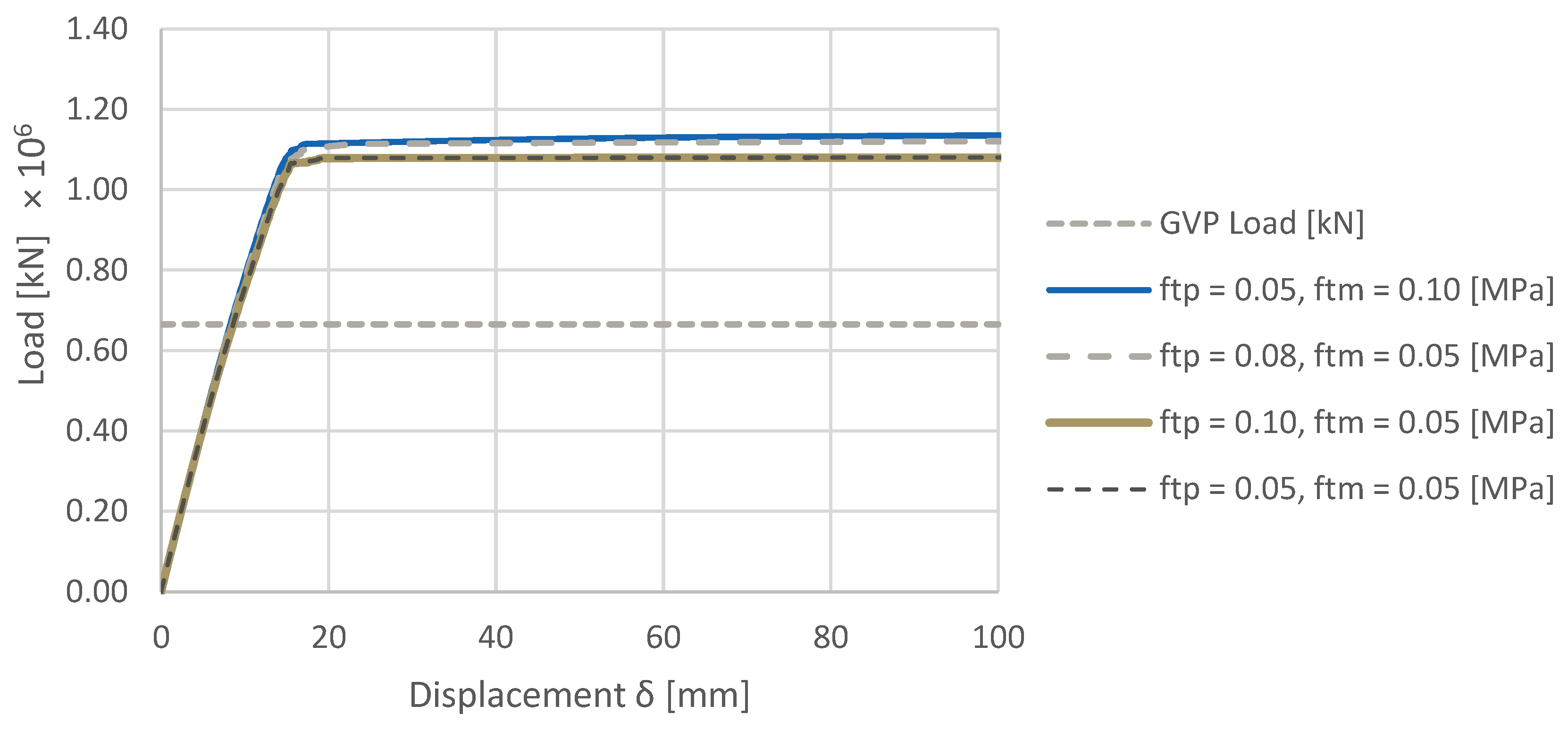
| fT,p, fT,m [MPa] | fC [MPa] | Time [min] |
|---|---|---|
| 0.05, 0.10 | 1.69 | 250 |
| 0.08, 0.05 | 1.69 | 252 |
| 0.05, 0.05 | 1.69 | 200 |
| 0.10, 0.05 | 1.69 | 141 |
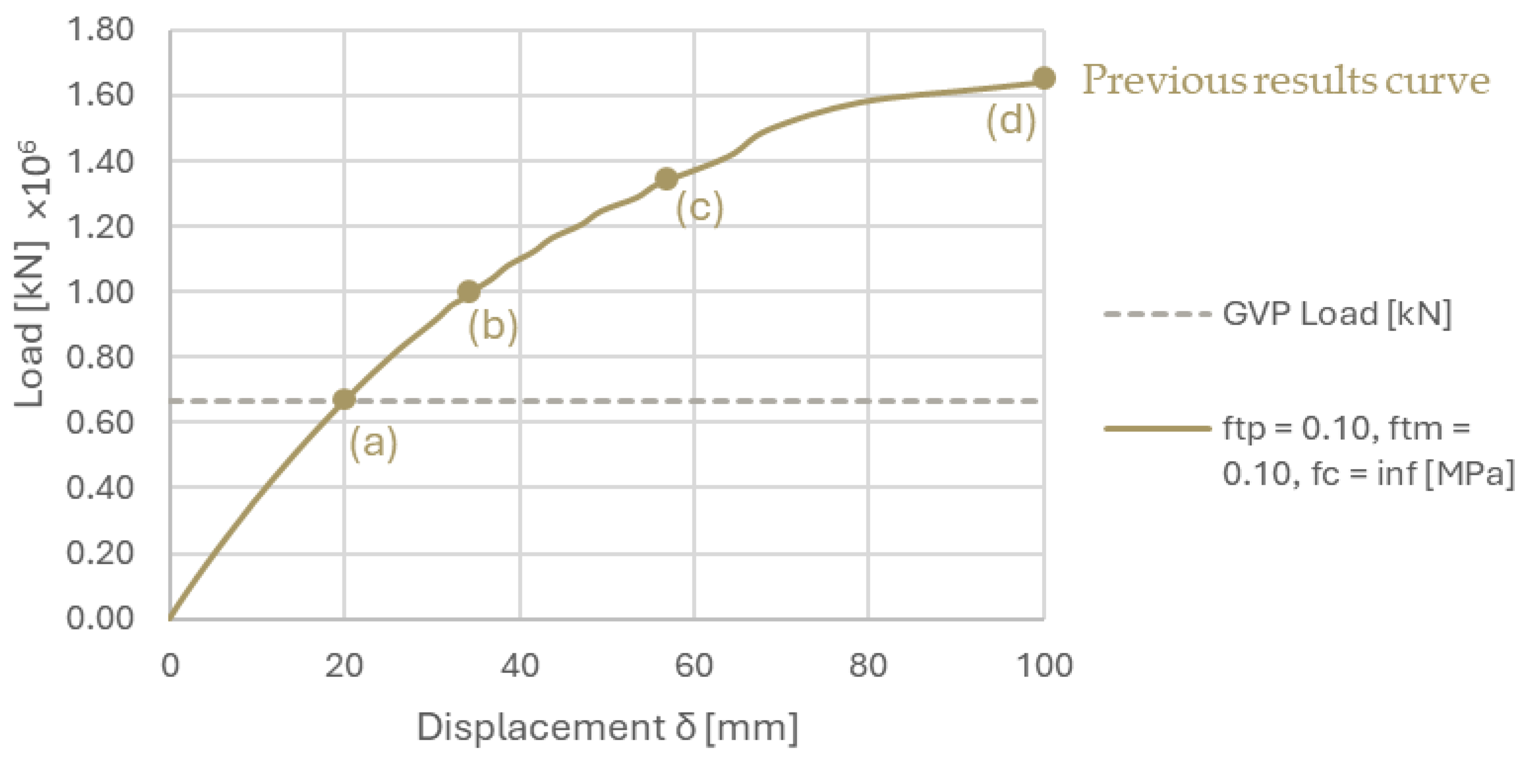
| 0.10, 0.10 | inf. | 42 |
| fT,m [MPa] | fC [MPa] | Time [min] |
|---|---|---|
| 0.05 | 1.69 | 83 |
| 0.10 | 1.69 | 107 |
| 0.05 | inf. | 9 |
| Fast LA [33] | FE, EBSM This Study | ||
|---|---|---|---|
| Assumed Density | kg/m3 | 2000 | 2530 |
| Young’s Modulus | MPa | Rigid | 2788.5 |
| Segmental Dome Weight (WSD) | kN | 6.96·105 * | 6.65·105 * |
| Collapse load λ (LF·WSD) | kN | 15.73 × 10⁵ (3D) ** | 16.6 × 10⁵ (3D) *** 9.31 × 10⁵ (2D) |
Disclaimer/Publisher’s Note: The statements, opinions and data contained in all publications are solely those of the individual author(s) and contributor(s) and not of MDPI and/or the editor(s). MDPI and/or the editor(s) disclaim responsibility for any injury to people or property resulting from any ideas, methods, instructions or products referred to in the content. |
© 2025 by the authors. Licensee MDPI, Basel, Switzerland. This article is an open access article distributed under the terms and conditions of the Creative Commons Attribution (CC BY) license (https://creativecommons.org/licenses/by/4.0/).
Share and Cite
Gandolfi, A.; Pingaro, N.; Milani, G. Elastic Body Spring Method (EBSM) for the Stability Analysis of the Global Vipassana Pagoda in Mumbai, India. Buildings 2025, 15, 653. https://doi.org/10.3390/buildings15050653
Gandolfi A, Pingaro N, Milani G. Elastic Body Spring Method (EBSM) for the Stability Analysis of the Global Vipassana Pagoda in Mumbai, India. Buildings. 2025; 15(5):653. https://doi.org/10.3390/buildings15050653
Chicago/Turabian StyleGandolfi, Alessandro, Natalia Pingaro, and Gabriele Milani. 2025. "Elastic Body Spring Method (EBSM) for the Stability Analysis of the Global Vipassana Pagoda in Mumbai, India" Buildings 15, no. 5: 653. https://doi.org/10.3390/buildings15050653
APA StyleGandolfi, A., Pingaro, N., & Milani, G. (2025). Elastic Body Spring Method (EBSM) for the Stability Analysis of the Global Vipassana Pagoda in Mumbai, India. Buildings, 15(5), 653. https://doi.org/10.3390/buildings15050653