Article

Comprehensive Design Process of CEB-Reinforced Masonry Panels for Earthquake and Hurricane-Resilient Houses

1
Environmental Engineering Graduate Program, Civil Construction Department, Polytechnic School, Federal University of Rio de Janeiro, Rio de Janeiro 21941-909, Brazil
2
Urban Engineering Graduate Program, Polytechnic School, Federal University of Rio de Janeiro, Rio de Janeiro 21941-909, Brazil
3
CERIS—Civil Engineering Research and Innovation for Sustainability, Department of Civil Engineering, University of Aveiro, 3810-193 Aveiro, Portugal
4
CICECO—Aveiro Institute of Materials, Department of Materials and Ceramic Engineering, University of Aveiro, 3810-193 Aveiro, Portugal
5
Civil Engineering Department, Polytechnic Institute, Federal University of Rio de Janeiro, Macaé 27930-560, Brazil
6
Civil Engineering Graduate Program, COPPE—Alberto Luiz Coimbra Institute of Graduate Studies and Research in Engineering, Federal University of Rio de Janeiro, Rio de Janeiro 21941-598, Brazil
7
Graphic Expression Department, Polytechnic School, Federal University of Rio de Janeiro, Rio de Janeiro 21941-909, Brazil
*
Author to whom correspondence should be addressed.
Buildings 2025, 15(17), 3242; https://doi.org/10.3390/buildings15173242
Submission received: 25 July 2025 / Revised: 28 August 2025 / Accepted: 3 September 2025 / Published: 8 September 2025
(This article belongs to the Special Issue Reliability and Risk Assessment of Building Structures)

Abstract

Among the threats capable of causing disasters, earthquakes and hurricanes are those that most significantly impact the structures of buildings. This collaboration between UFRJ (Brazil) and UA (Portugal) aims to develop a house model that is both earthquake- and hurricane-resistant, within a specific range of magnitude to be determined, utilizing straightforward, affordable, and eco-friendly construction methods. SHS-Multirisk was developed under two phases. The first one carried out the design of the SHS-Multirisk 1.0 house model and the second phase comprised the preliminary conception of the SHS-Multirisk 2.0 architecture integrated with structural panels. This paper focuses on presenting the comprehensive research, development, and innovation (R&D&I) process of compressed earth block-reinforced masonry panels and the preliminary evaluation of their technical feasibility to be applied in SHS-Multirisk 2.0 house models. The steps of the process were explored in detail throughout process implementation, which revealed successive multi- and interdisciplinary challenges.

1. Introduction

Based on data from the Emergency Disaster Database [1], over 175 million people are impacted by disasters annually, resulting in more than 64 thousand deaths each year, considering the period from 2003 to 2022. In every disaster, housing loss ranks as the second most critical issue, following the loss of human lives.
Among the threats capable of causing disasters, earthquakes and hurricanes significantly impact the structures of buildings and are very unpredictable. Unfortunately, many developing nations suffer from these types of threats, severely affecting highly vulnerable groups’ social and economic development [2,3].
Earthquakes have been responsible for extensive infrastructure damage, causing significant economic and social losses on a global scale. The costs caused by seismic events go beyond physical damage, encompassing recovery and rehabilitation challenges that extend for several years after the event, including indirect economic disruptions such as productivity losses and long-term social impacts [4,5]. Additionally, earthquakes’ socio-economic impacts manifest in the deterioration of social well-being and the intensification of the affected communities’ vulnerabilities. This complex interface between direct and indirect damage highlights the importance of interdisciplinary strategies that integrate technological approaches, public policies, and risk management practices to promote resilience and accelerate the recovery of impacted territories [6,7].
Aiming to illustrate this complexity, Aydin et al. [8] provide a detailed report of the catastrophic physical, patrimonial, and social damage caused by the 6th of February 2023 magnitude 7.7 and 7.6 earthquakes in Türkiye. Over 518,000 residential units were destroyed/severely damaged/demolished immediately, including schools, hospitals, and cultural landmarks, while 62,013 lives were lost (53,537 people in Türkiye and 8476 in Syria) and more than 100,000 people were injured. While 2 million people experienced shelter problems, the earthquakes devastated 11 provinces and over 5 million people migrated to different regions. Historic structures, such as mosques and cultural centers, suffered irreparable damage, erasing parts of Türkiye’s rich heritage. Socially, the disaster led to widespread trauma, mental health challenges, and disruptions in education and healthcare services, with 42 hospitals sustaining severe or moderate damage. The long-term socio-economic impacts, including unemployment, migration, and financial strain, continue to challenge recovery efforts.
Compressed earth block (CEB)-reinforced masonry technology holds significant promise for use in humanitarian emergencies and multi-hazard resilient construction, mainly because of its environmental, economic, and social benefits, including the use of locally sourced materials with minimal environmental impact and the involvement of beneficiaries in the construction process [9,10]. Nonetheless, this technology has certain limitations that require further understanding to ensure resilient construction, particularly as in-plane and out-of-plane shear pose challenges for masonry under seismic forces [11,12].
The SHS—Simple Housing Solution—Project [13,14] is a framework for (re)constructing homes and small buildings through a collaborative community-based approach. It aims to maximize resource efficiency and help restore order in critical scenarios, such as post-disaster recovery, post-conflict rebuilding, refugee resettlement, or risk mitigation efforts.
SHS is grounded in the core principles for sustainable housing restoration outlined by the United Nations Development Program (UNDP) and the International Recovery Platform (IRP), focusing on environmental, technical, financial, and socio-organizational sustainability. Recognized as one of the 16 finalists for the 2019 Sasakawa Awards, the project aligns with the Sendai Framework for Disaster Risk Reduction [15] and contributes to various sustainable development goals (1, 3, 4, 5, 6, 8, 9, 10, 11, 12, 13, 16, and 17). A Haitian civil engineer who graduated from the Federal University of Rio de Janeiro (UFRJ) applies knowledge from the SHS Project in social projects in Haiti [16].
SHS-Multirisk is a research, development, and innovation (R&D&I) spin-off initiative being developed through collaboration between UFRJ and the University of Aveiro (UA). The project aims to create a housing model designed to withstand both earthquakes and hurricanes, with the specific magnitude range currently under study. Furthermore, it uses simple, low-cost, and environmentally friendly construction technologies compared to traditional alternatives or more technological but less accessible ones. The first SHS-Multirisk house model is being improved in this phase, targeting more aggressive scenarios.
While earthen construction technologies such as compressed earth blocks (CEBs) have been explored in various housing initiatives (see Section 2.2), few studies have evaluated their structural performance under earthquake and/or hurricane loads. Previous research has shown that natural fiber reinforcements such as reeds and bagasse improve CEB strength and ductility [17,18]. In the same direction, numerical simulations confirm that optimized mortar and sisal fibers further enhance performance [19], and adding cement to the earth increases the mechanical strength and durability of the blocks, reducing the risks of cracking or collapse [20]. Although Zarzour et al. [21] carried out a seismic design of a CEB low-carbon building, multi-hazard applications remain largely unexplored.
The existing literature often focuses on component-level testing or theoretical modeling, with limited emphasis on full-scale experimental validation and architectural integration. This study addresses that gap by presenting a proposal for reinforced CEB masonry panels designed for combined earthquake and hurricane resilience, tested under cyclic loading and embedded within a community-based housing framework. The originality of this work lies in its interdisciplinary approach, merging technical innovation with socio-economic–environmental feasibility to support disaster-prone communities.
The aim of this paper is to detail the comprehensive R&D&I process behind the reinforced masonry panels utilized in the SHS-Multirisk 2.0 residential model and provide preliminary analysis on how the results may affect house performance under seismic scenarios. The paper is aligned with the Sendai Framework for Disaster Risk Reduction (2015–2030) [15] and the Paris Agreement on Climate Change (2015).
Masonry structures are particularly vulnerable to seismic actions, displaying brittle behavior and limited energy dissipation. Non-destructive post-seismic studies highlight the importance of experimental validation under extreme loading [22] and typical forms of masonry damage in earthquakes include cracking (horizontal, vertical, or diagonal cracks), displacement (masonry components can shift or be displaced from their original positions), collapse, shear failure, and foundation damage [23]. Among these, out-of-plane failures stand out as one of the most severe problems, often triggered by poor connections between walls and diaphragms [24]. The prevalence of these damage modes has been consistently observed in post-earthquake surveys, confirming that out-of-plane instability remains a key vulnerability in unreinforced masonry construction [25,26]. Except for foundation damage, SHS-Multirisk experiments were planned to understand these damage modes in full-scale reinforced panels, thus increasing predictability in real case situations.
Considering the high number of experiments carried out and the complexity on the analysis of each one, quantitative analyses on the experiments’ outputs are clearly out of the scope of this paper. However, the key experiments which led to critical decisions within the R&D&I process had their quantitative analyses included in the scope of this article or were referenced from other published works. It is necessary to highlight that there are also extensive qualitative partial results throughout the entire process and comprehensive process implementation revealed significant multi- and interdisciplinary challenges. The main result is the successful development of SHS-Multirisk 2.0 house panels.

2. General Aspects of Proposed Housing Solution

Low-cost earthquake-resistant constructions represent an indispensable approach to mitigate the impacts of seismic events, especially in economically vulnerable regions with high seismic activity.
In this context, the optimization of structural systems and the incorporation of alternative materials that promote high ductility and energy dissipation capacity emerge as fundamental strategies. The development of integrated solutions, combining traditional methods with emerging technologies, can significantly improve the resilience of buildings while maintaining the economic viability of projects.
Additionally, the integration of advanced computational modeling techniques and real-time structural monitoring systems has provided new horizons for the development of low-cost earthquake-resistant methods.

2.1. The Constructive Technology

Over the past decades, global concerns regarding energy, environmental, ecological, and economic challenges have led to the recognition of raw earth as a viable and sustainable building material [27,28,29]. Among the earthen construction technologies, CEBs appear as an evolution from adobe [30] and consist of pressing a mixture of non-plant–soil consisting of sand, fine particles (silt and clay), and water, to which binder materials (cement or lime) may be added for soil stabilization and strength increasing. In this work, the term CEB refers to blocks created by compressing a mixture of soil that has been stabilized with cement and water, possibly adding hydrated lime.
The pressing process, whether manual or automated, enables the production of modular blocks with consistent dimensions, often featuring hollows. However, the uniformity of the blocks’ dimensions is heavily influenced by factors such as the production method, soil type, particle size distribution, and mixture’s moisture. Using hand presses can lead to notable variations in the manufacturing process, particularly in the block’s height. Therefore, applying mortar layers in CEB masonry is strongly advised to ensure better stress distribution across the masonry elements. However, hand presses do not demand electrical supply, are easy to operate, and are very cheap machines when compared to automatic presses.
According to [31], stabilizing the earth with cement and/or lime minimizes retraction, which is influenced by the clay content and water percentage in the mixture, thereby reducing the formation of cracks in the blocks as they lose moisture. Additionally, it enhances the dry unit weight of CEBs, improving their performance in areas such as compressive strength, thermal insulation, impermeability, and durability, with the latter being linked to decreased water exposure. It is also important to mention that the fungicidal property of lime in the mixture [32] emphasizes that the binder ratios in a soil mixture can differ depending on the varying soil characteristics in different locations.
The modular nature of CEBs allows for fast and tidy construction through block interlocking, making it ideal for architectural designs with dimensions that are multiples of ½ block to minimize cutting and material waste. For use in reinforced masonry panels, CEBs should have a hollow design with two holes, some of which are reinforced with steel bars embedded in micro-concrete or mortar to enhance the structural system’s flexibility. Moreover, the holes in the blocks enable the integration of electrical pipes within the structure, while water, sewage, or gas pipes are prohibited in masonry serving a structural purpose. The visual masonry appeal can be enhanced by using exposed blocks coated with a thin layer of water-resistant resins or acrylic finishes. The protective coating, along with the waterproof layer at the base of the walls, is essential to avoid water exposure, which can accelerate the blocks’ deterioration over time.
The application of CEB-reinforced masonry technology for (re)construction in disaster scenarios has been thoroughly analyzed and discussed in [9].

2.2. Real Applications in Communitary Works

Compressed earth blocks (CEBs) have been successfully applied in various community construction projects worldwide, demonstrating their potential for sustainable and affordable housing. In Uganda, organizations like HYT and Smart Havens Africa have utilized interlocking stabilized soil blocks (ISSBs) to build affordable housing for vulnerable groups [32,33]. Moreira also illustrates an application of CEB houses in Malawi [34]. In India, the Auroville Earth Institute has developed advanced CSEB technologies, enabling multi-story residential buildings and post-disaster housing reconstruction [35]. Similarly, in Nepal, Community Impact Nepal has facilitated the construction of over 3500 earthquake-resistant homes using ISSBs, empowering local entrepreneurs and communities [36,37]. In Mexico, Échale has implemented a self-construction model using CSEBs, resulting in significant community engagement and one million lives being improved, with 30,000 new houses and 150,000 house improvements carried out [38]. These cases highlight the versatility and social impact of CEBs in addressing housing shortages and promoting sustainable development.
It is important to highlight two ongoing applications in Haiti that are SHS-based. At Don de L’Ámitié and Lacombe, more than 50 multi-hazard houses were constructed by communities, in social arrangements coordinated by a civil engineer who graduated from UFRJ and former SHS team member. This partnership between the NGOs Village Marie Haiti and Techo Haiti is truly transforming Haitian communities towards sustainable development, joining housing provision, strengthening social ties, improvement of livelihoods, education and training, child protection, food safety, health protection, and technology and economic development [16,39,40].

2.3. SHS-Multirisk Project Timeline

The project runs under two phases:
  • Phase 1: UFRJ. In 2018 and 2019, studies of threats from strong winds [41] and earthquakes [42] took place at UFRJ, when a first detailed experimental phase was carried out and enabled the first design of the SHS-Multirisk 1.0 model. From mid-2019 to March 2020, immediately before the first lockdown due to the COVID-19 pandemic, the second experimental phase took place at the UFRJ Campus Fundão facilities, when shear tests were carried out on 16 wallets aiming to understand the contribution of the following factors in shear strength: arrangement of reinforcing joists along the height, percentage of reinforced vertically holes, and the existence of rough coating with plaster. Authors from UFRJ participated in this phase.
  • Phase 2: UFRJ-UA Partnership. In April 2021, the partnership between UFRJ and UA began though a postdoctoral internship of the first author at UA, under the supervision of the second author and in collaboration with other authors from UA. The first phase results were used as inputs to the second phase. The aim was to define types of reinforced masonry panels and carry out a broad experimental program [43], intending to understand the cyclical behavior of full-scale panels for in-plane and out-of-plane bending shear and determine the mechanical properties of the masonry and its components through static tests. Based on these results, the residential model SHS-Multirisk 2.0 was proposed.

2.4. Overall Multi-Risk House Conception

The design of a multi-risk house is an iterative process, as it involves an architectural design that must be fully integrated with structural elements design, especially the panels that make up the walls and the roof’s elements.
Another point worth highlighting is the high interdisciplinarity involving many aspects of earthquake and hurricane threats, adding additional complexity to the design. These interferences occur mainly in the way the loads act on the designed system, which can lead to conflicting design criteria. For example, from a seismic point of view, the house symmetry is desirable, including the symmetry of the openings, but from a wind-load point of view, the existence of openings on all facades does not offer the most favorable configuration.
When these conflicting criteria arose, it was decided to give priority to the design most favorable to the seismic threat, since in the investigations of the SHS-Multirisk 1.0 model, the forces resulting from seismic loads were critical for dimensioning the structural elements. However, as a general rule, solutions were sought that could be useful for performance against both seismic and hurricane threats, such as the panel’s height limitation, chosen to coincide with the top of the doors. The lower panels’ height reduces the bending efforts at the base for both threats and reduces the shear forces in earthquakes, since the panels are lighter and less subject to the effects of seismic accelerations.
Construction technique simplicity was also a design criterion, considering that the objective is to provide a solution that can be implemented directly by communities vulnerable to seismic threats and hurricanes, as is the case of Haiti, Nepal, among other countries. Therefore, complex solutions were discarded, while the aim was to extract maximum performance from simplicity. This is the case, for example, of the use of wooden elements to provide ties at the top of the panels, serving both as a lintel and as support for the roof rafters.

2.4.1. The SHS-Multirisk 1.0 House Model

The complete development process of this house model (Figure 1) involved an experimental campaign and computational analysis, which are detailed in [9].
The analysis determined that the SHS-Multirisk 1.0 model, constructed with CEB structural masonry, is capable of withstanding earthquakes with accelerations up to 0.20 g PGA (equivalent to a horizontal force of 82.58 kN) across Class A, B, C, or D terrains in a near-collapse limit state. This level of acceleration is comparable to the earthquake experienced in Haiti in 2018.
It was determined that a structure similar to the proposed design, but with a different arrangement of openings, could endure wind forces associated with speeds of up to 35 m/s (126 km/h) [41], provided certain reinforcements are implemented and the roof tiles are detached to create a fuse effect.

2.4.2. The SHS-Multirisk 2.0 Preliminary House Model

The preliminary architectural design is closely linked to the panels’ design and was developed interactively, seeking to take advantage of the best practices performed in the SHS-Multirisk 1.0 model and optimize the points identified as critical in the previous design.
In addition, an attempt was made to use local materials (mainly wood and earth) more intensively and propose simple innovations for the context of earthquakes and hurricanes that the communities themselves could implement.
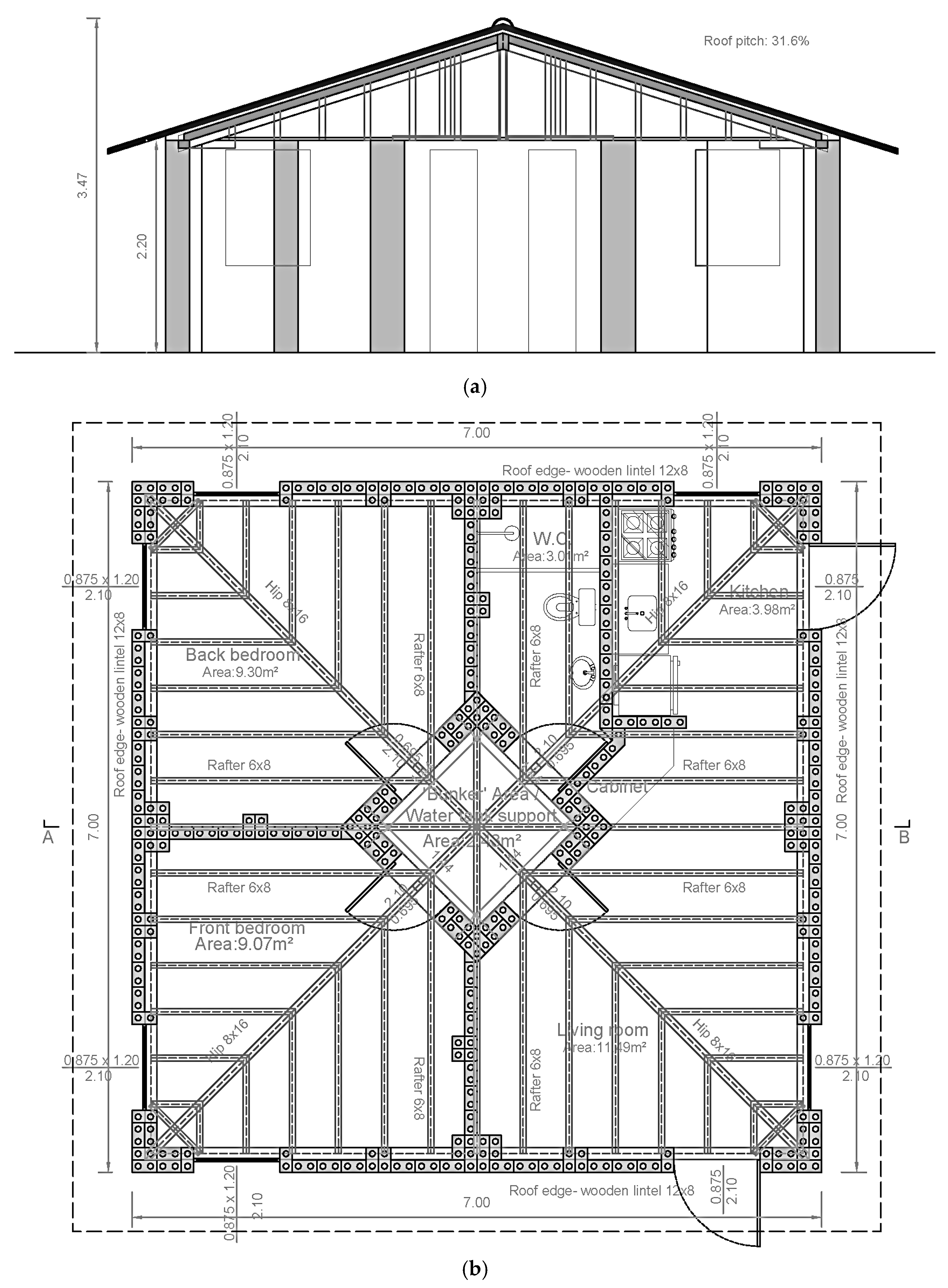
Among the characteristics listed for the preliminary SHS-Multisk 2.0 model (under development; Figure 2) the following can be mentioned:
  • House with just one floor and low ceiling height on the borders (next to 220 cm), which reduces bending moments at the base and wind pressures on the masonry panels, in addition to simplifying the work.
  • Absence of a slab, which reduces bending moments at the bottom of the panels and simplifies the construction process.
  • Roofs with semi-loose tiles, aiming at the formation of openings in the roof during strong winds and the consequent reduction in the pressure difference in the masonry panels (fuse effect).
  • Maximization of symmetry in masonry and openings, which increases predictability and symmetry in the house’s response to different angles of horizontal force incidences.
  • The adoption of the walls’ design as a combination of individualized patterned panels rather than panels with varying dimensions. By using a set of panels with similar stiffness, it is possible to conceive a resistant scheme that favors global torsional behavior and allows for flexible architectural options, within certain limits that are currently being studied. It also favors better distribution of loads and damage, increasing the predictability even in more advanced stages of damage. In addition, it is possible to recover the elements in isolation, reducing costs.
  • To simplify the construction process, only two panel geometries were adopted, C and L, which are integrated into the preliminary model of Figure 2, along with the other elements mentioned above. Roof options are under study.
  • Opening of external doors to the outside of the house, making it easier for residents to leave in the event of a disaster occurrence. Opening doors to the outside, as well as opening internal doors towards outside the ‘bunker’ area, also makes it easier for residents to break down doors if these elements are jammed after the adverse event.
  • The use of timber to brace the panels against their out-of-plane behavior, allowing the transfer of forces/displacements to the panels with in-plane behavior (bracing system and tensioned timber lines).
  • Masonry lintel’s elimination and use of the wooden beam on the roof edge as a slight lintel.
  • Presence of stiffeners at each meter of masonry on the sides of door and window openings.
  • Presence of a central core of L-shaped panels to function as a ‘bunker’ for emergency shelter for up to six people during hurricanes and as an isolated support structure for the water tank.
  • Overall cost limitation for a house of smaller than 50 m2, considering that the project’s target audience is composed of vulnerable communities and larger houses could make the project economically unfeasible.

2.5. Novel Contribution and Advantages of House 2.0’s Panels

Table 1 provides a comparison between issues that compromise the structural integrity and earthquake resilience of masonry buildings [45] and SHS 2.0 panels’ characteristics.
Furthermore, there are other aspects that evidence SHS 2.0 panels’ strengths:
  • Panels’ geometry allows for the creation of a bunker region inside the house, what differentiates SHS 2.0 concept and design.
  • Panels’ typologies and geometry allow for symmetric distribution of loads and resistances, contributing to house’s predictable behavior in different directions.
  • The construction technology adopted in the panels makes it easy to carry out maintenance and recovery of damaged panels.
  • The panels’ design was integrated into a special multi- and interdisciplinary design, making it possible to face hurricane and earthquake hazards.
  • The adopted technology allows for self-construction and has low environmental impacts.
  • The findings have practical implications for vulnerable communities in disaster-prone regions, offering a viable solution for housing reconstruction and risk mitigation.

3. Materials and Methods

Considering that the proposal for structural CEB masonry panels for the SHS-Multirisk 2.0 house model is an innovative process, discovering these elements’ mechanical behavior required a specific experimental research program, adding complexity to the house design process.
The iterative architecture/structure design process consists of the following steps:
(a)
Preliminary architectural design (Section 2.4.1);
(b)
Preliminary structural panels’ design (Section 3.1);
(c)
Panels’ introductory experimental study (Section 3.2);
(d)
New panels’ design (Section 3.3);
(e)
New architectural design (Section 2.4.2);
(f)
Panels’ main experimental study (Section 3.4);
(g)
Panels’ design improvement (Section 3.5);
(h)
Architectural design improvement;
(i)
House 2.0 computer modeling;
(j)
House 2.0 structural behavior analysis under different load scenarios;
(k)
Adjustments and obtaining the final residence model.
The research conducted in phase 2 is currently in step ‘h’, so this article only addresses the panels’ design process (items ‘a’ to ‘g’) and a preliminary evaluation of its impact on the house’s performance.

3.1. Strucutural Panels’ Preliminary Design

The structural panels’ initial design was based on the outputs obtained from the SHS-Multirisk 1.0 residential model. The aim was to take advantage of the successful features of the previous model and add modifications to improve the panels’ performance. The main changes were in the panels’ shape, the distribution of reinforcement, and in the uniformity in the materials used.
In the SHS-Multirisk 1.0 model, 1 m spaced stiffeners were adopted along the masonry. The stiffeners also acted as reinforcement on the openings’ borders and improved the panel’s performance for out-of-plane bending shear. Reinforced concrete joists were adopted in the middle and at the top of masonry, as well as reinforced concrete columns in some vertical block holes.
In this model, frames measuring approximately 1 m wide by 1.10 m high (there were two frames along the 2.20 m high wall) played a central role in the house’s structural behavior, since they allowed for the formation of compressed diagonals when the residence was subjected to horizontal forces. This behavior was confirmed by pushover tests detailed in [9].
For the SHS-Multirisk 2.0 house, the basic modulation of the 1 m wide by 2.20 m high for one single panel was adopted, using 25 cm long by 12.5 cm wide compressed earth blocks with holes and maintaining stiffeners and horizontal/vertical reinforcement, with the aim of improving strength and ductility.
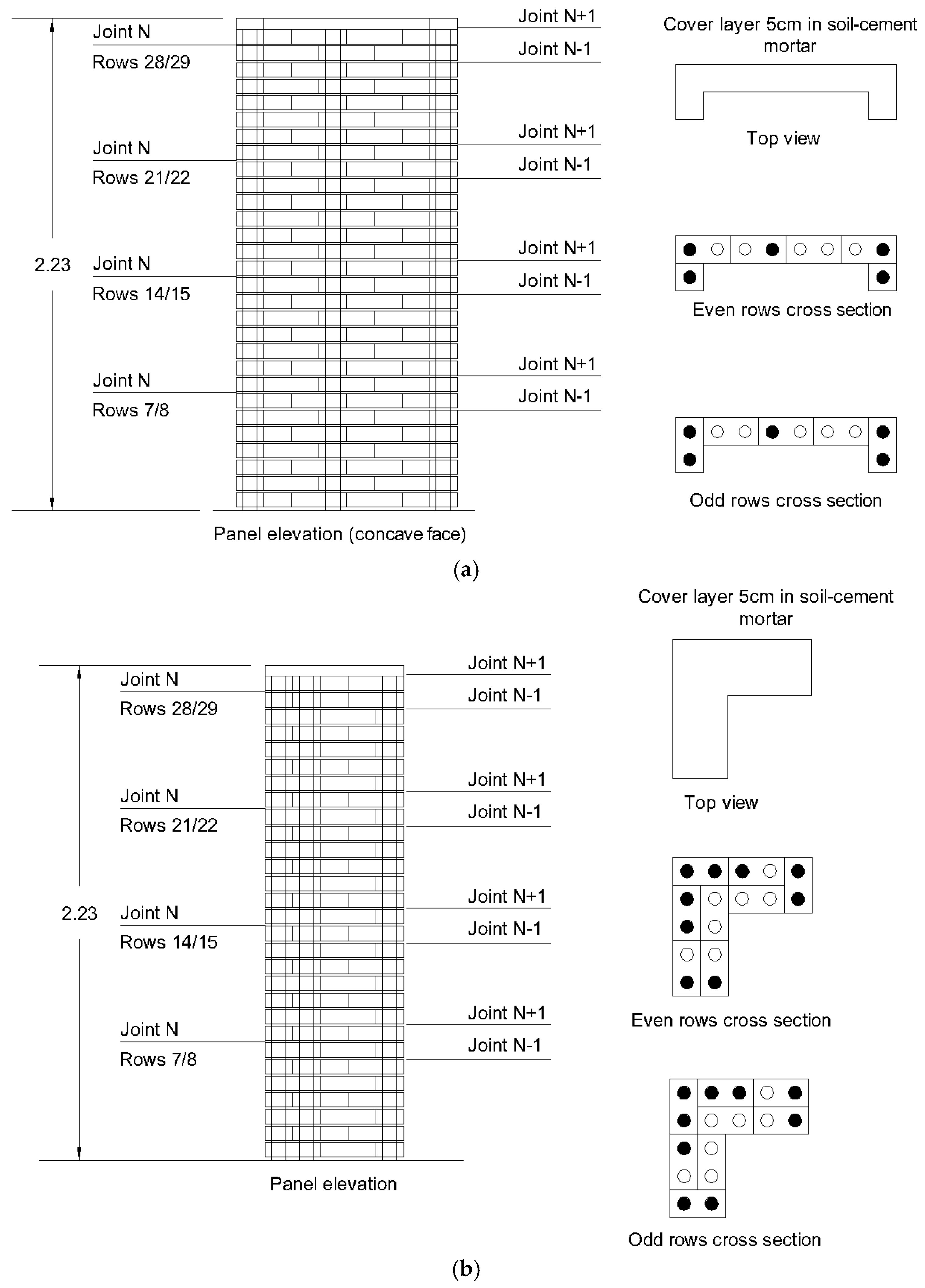
Only two types of panels were selected to compose the design of the entire house: C and L (Figure 3). While the L-type panel was used in the corners and in the bunker area, the C-type panel was used in the other situations, being the most common one (Figure 2).
Another relevant aspect was the replacement of the former concrete vertical and horizontal elements by soil/cement mortar, aiming to provide greater material homogeneity and reduce adverse effects from the interaction between the cement/sand and cement/soil mortar elements. Through this criterion, it was also possible to maximize the use of local materials and minimize the environmental impact, in line with the project objectives. Soil/lime mortar was initially considered, as it is similarly used in adobe blocks. However, the need for better adhesion between the mortar and the reinforcements led to the option of using cement mixed with soil in the mortars.
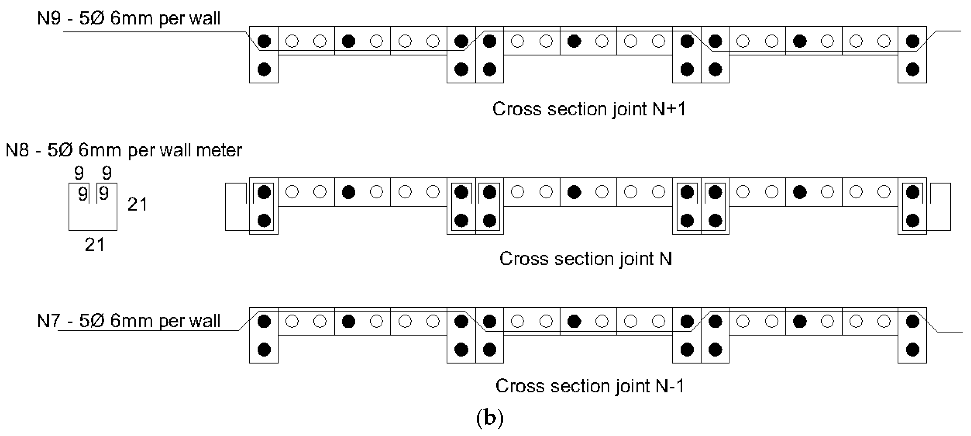
In line with SHS design guidelines for simplicity, the original panel’s horizontal beams were eliminated and replaced by reinforced mortar joints in certain positions. The panels’ upper part contained U-shaped steel bars in the block holes that comprise the stiffeners, aiming to allow the passage of wooden elements that make up the roof support in the SHS-Multirisk 2.0 house model.

3.2. Panels’ Introductory Experimental Study

From the preliminary design described in Section 3.1, the first experimental needs were identified, aiming to understand the panels’ characteristics that could lead to a more reliable design and offer improved performance at in-plane bending shear.
The panels’ introductory experimental study was developed in two stages:
  • Multifactorial experiment in wallets. Since the ability to withstand horizontal forces depends on compression and tensile elements, it was necessary to improve the understanding of how these elements could be modified, aiming to obtain better panel performance. Thus, an experimental program was developed in Brazil, from 2019 to 2020, consisting of a multifactorial experiment with 16 wallets, with the objective of understanding the influence of the following factors on the panels’ shear strength: arrangement of reinforcing joists along the height, percentage of holes reinforced vertically, and the existence of rough coating with plaster.
  • Experiments to select components. In 2021, at the University of Aveiro, experiments were carried out to select the mix that would be used in the mortars for manufacturing the blocks, in the coating, and in the filling of the joints and holes in the blocks. Furthermore, tests were carried out to verify the adhesion between the soil/cement mortar and reinforcement, aiming to provide assertive choices for the experimental campaign performed in phase 2. These results can be found in [43].

3.2.1. Multifactorial Shear Experiment on Wallets

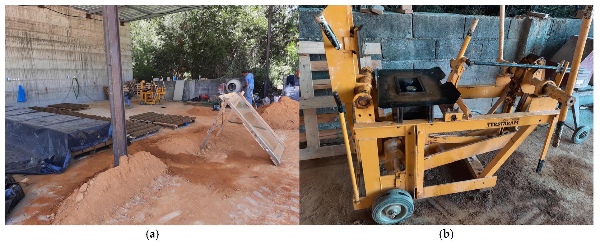
In June 2019, CEBs measuring 250 mm in length, 125 mm in width, and approximately 65 mm in height were produced at UFRJ facilities located in Macaé, Rio de Janeiro, Brazil (Figure 4b). The blocks were produced using a mechanical hand press (Figure 4a) and a blend of two types of soil. The mixture included cement type II-32 as a binder in a 6:1 ratio (6 parts soil to 1 part cement by volume), along with 2% hydrated lime and approximately 20% of water content by volume. The soil moisture was manually adjusted based on tactile assessment to simulate real-world conditions, where the community would handle this process during SHS implementation. It is important to note that water content can vary significantly depending on the type of soil. The water absorption and CEBs’ compressive strength were tested in accordance with the NBR 8492:2012 standard [46]. In January 2020, the blocks were transported to UFRJ Campus Fundão facilities, at Rio de Janeiro city. The wall panels were built in February 2020 and tested in March 2020, after 28 days (Figure 5).
From mid-2019 to March 2020, pushover shear tests were carried out on eight types of wallets, with two replicates each:
  • 1V.GP.SE: One joist, 50% of the holes grouted and without plaster.
  • 1V.GT.SE: One joist, 100% of the holes grouted and without plaster.
  • 1V.GP.CE: One joist, 50% of holes grouted and plastered.
  • 1V.GT.CE: One joist, 100% of holes grouted and plastered.
  • 2V.GP.SE: One joist at the top and one in the middle, 50% of the holes grouted and without plaster.
  • 2V.GT.SE: One top joist and one intermediate, 100% of the holes grouted and without plaster.
  • 2V.GP.CE: One joist at the top and another in the middle, 50% of the holes grouted and plastered.
  • 2V.GT.CE: One joist at the top and one in the middle, 100% of the holes grouted and plastered.
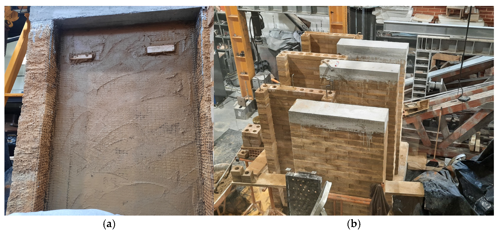
Figure 5 shows the construction of wallet specimens for shear tests in UFRJ/Brazil.
The modified shear test (pushover) involved applying a horizontal force to the top of the wallet specimens (Figure 6). Each specimen measured 1 m in length, corresponding to four blocks per row, with a single leaf of ½ block width (eventually covered with a 2 cm layer of plaster in the proportion 1:3:1—cement, sand, lime—in both sides) and a total height next to 90 cm. Each specimen was constructed with blocks placed in mortar joints approximately 1 cm thick, mixed manually in a 6:1 ratio of soil to cement by volume. The reinforced concrete joist matched the blocks’ width, and some vertical holes were reinforced and filled with grout. The grout was prepared manually using a 1:4:2 ratio of cement, sand, and 3/8” stone gravel by volume. Reinforcement included 1/4” CA 50 steel bars, with one bar per hole and two bars per horizontal joist. To prevent rotation, a steel vertical support was embedded in the concrete base to stabilize the wall near the load application point, without imposing significant restrictions on movement in the direction of the applied load. Additionally, a steel angle was installed at the bottom of the wallet, on the opposite corner of the load application point, to prevent overall translation.
The load was manually applied and incrementally increased using a hydraulic jack placed at the center of the top concrete joist section. Each load stage averaged 150 kg. Since the process was manual, the load application rates were not precisely controlled. However, a waiting period of approximately 30 s was observed at each stage to stabilize displacements. Displacement measurements were taken using linear variable differential transformers (LVDTs) positioned at four levels along the walls’ height, labeled as LVDTs 1, 2, 3, and 4, from top to bottom. A load cell was utilized to measure the applied load. Both displacement and load data were recorded simultaneously through a data acquisition system. Figure 6 illustrates the set up used for the horizontal tests.
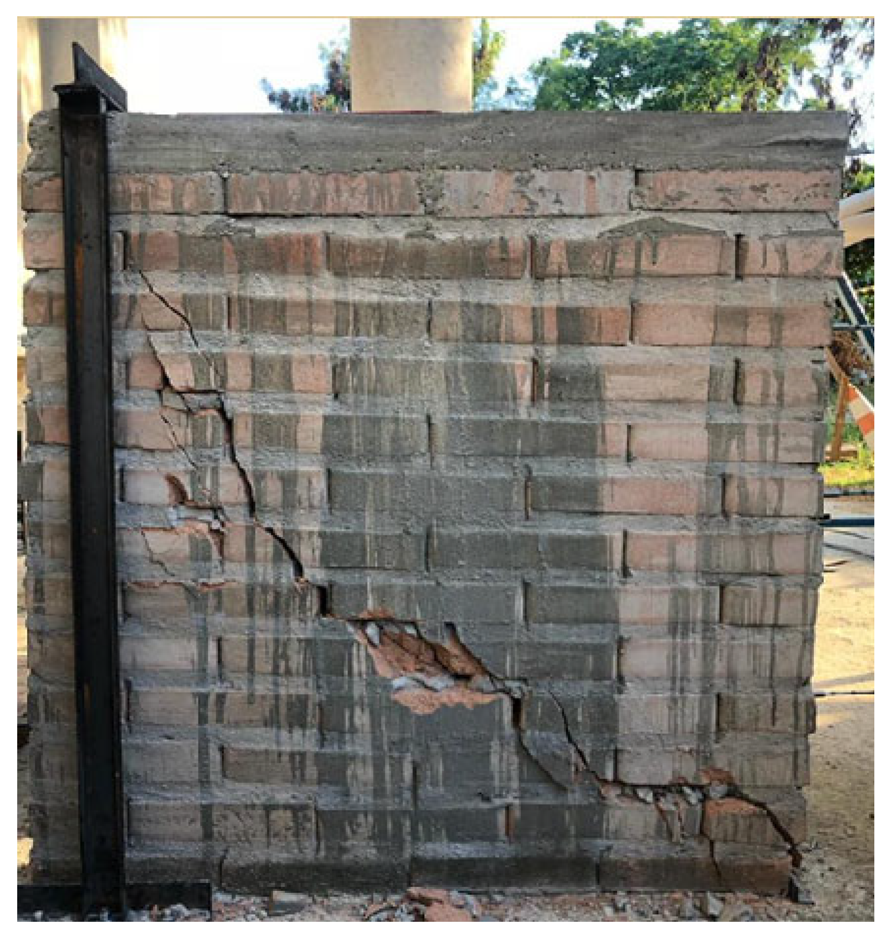
Figure 7 shows a crack in one of the sixteen wallets after the horizontal load test at UFRJ/Brazil.
Multifactorial Experiment Analysis
While the average in-plane shear force and the coefficient of variation were obtained from the data of two specimens tested in each typology, the masses were estimated based on the panels’ geometric characteristics and the components’ (blocks, mortars, and micro-concrete) average unitary weights.
As each panel type has a typical mass per area value, and these masses are mobilized during seismic events generating loads on the panels, an attempt was made to define a parameter that relativized the shear force to the panel’s mass. Thus, the parameter ‘resistant shear force/mass per square meter’, or simply ‘force/mass’, was calculated, which was taken as an indicator of the effective capacity of the panel’s in-plane shear, with acceleration units.
Considering the shear forces values corresponding to the panel typology adopted in the SHS-Multirisk 1.0 model (1V.GP.SE) as a reference, the effective shear force factors were calculated for seismic loads (i.e., based on the ‘force/mass’ parameter) and non-seismic loads (without considering the effect of mass, as in the case of wind loads). These factors represent, therefore, the extent to which typologies can overcome shear force compared to the reference panel.
Finally, from the SHS-Multirisk 1.0 model’s quantitative and budget worksheets [47], the house cost factors were calculated, representing the relationship between the house cost corresponding to different panel types and the cost of a house made with the basic typology (1V.GP.SE). These comparisons were made considering the cost option of construction with labor and materials (traditional system) and the option of construction in ‘mutirão’ (community or joint work system, where a good part of the labor comes from the community itself and is not reimbursed) + materials. In this way, it was also possible to evaluate the cost impacts in choosing the panels, and not just the strength aspects, avoiding economically unfeasible options.

3.2.2. Tests for Choosing New Panels’ Components

In the 2nd experimental phase, an expanded experimental campaign was planned, aimed at testing full-scale walls in bending shear behavior.
Before the blocks were manufactured, compressive strength and absorption tests were carried out at UA Civil Lab to choose the blocks’ materials proportions following NBR 8491:2012 [48] and NBR 8492:2012 [46]. They tested the mixtures 6:1, 8:1, and 10:1 (soil/cement). These mixture ratios were pre-selected based on former experiences in Brazil, regarding previous investigations and best practices from ABCP (Portland Cement Brazilian Association) senior specialists and from block producers.
The average mortar compressive strength was obtained by the prism test according to EN 1015-11:1999 [49]. Compression and flexion tests were carried out on different mixes based on the volume of the mortar, with basically two humidity types: dry mortar (approximate consistency to manufacture blocks, mixes 6:1, 7:1, 8:1) and wet mortar (consistency of plaster, mixes 5:1, 6:1, 7:1, 8:1). These mixture ratios were pre-selected based on the directive of using mortars with the same materials and proportions next to the ones used in CEB production, thus safeguarding chemical compatibility and durability in contact between mortars.
The shear effect at the mortar–block interface was also analyzed according to BS EN 1052-3:2002 [50] standard for different proportions in volume of wet mortar with plaster consistency (5:1, 6:1, 7:1, 8:1), aged 7 days.
Following EN 10080:2005 Annex D [51], pullout tests were carried out on 10 mm steel bars on three types of anchoring substrate, 6 days of age: micro-concrete mix by volume 1:4:2 (cement/sand/stone gravel), dry mortar mix by volume 8:1 (soil/cement, with 2% hydrated lime), and wet soil/cement 6:1 mortar.
Based on the test results for choosing the components, the mix selected for block production was 8:1, as it was the option with the best benefit/cost ratio. The mortar chosen for laying the blocks, plastering, and filling the holes with reinforcements was the soil/cement wet mortar in the 5:1 ratio, which would allow even better conditions for anchoring the reinforcements when compared to the 6:1 ratio. The plaster was reinforced with a square polyethylene mesh with a 10 mm opening. Quantitative results can be found in [43].

3.3. New Panels’ Design

After the conclusion of the introductory experiments in the 2nd phase, the first panels’ design review was carried out, obtaining a complete definition for the prototype panels’ construction. In addition to confirming the previously designed panels’ formats and dimensions, the positions, diameters and details of the reinforcements, the blocks and mortar mixes, the plaster’s thickness, and the specification of the structuring mesh embedded in the mortar coating were also established.

3.4. New Panels’ Main Experimental Study

To evaluate the designed panels’ behavior under earthquake and hurricane conditions, an extensive experimental program was developed. This program included cyclic bending shear tests, both in-plane and out-of-plane, conducted on full-scale type C panels with plaster, type C panels without plaster, and type L panels without plaster.
In addition to tests on full-scale panels, diagonal and axial compression tests were also carried out for mechanical characterization on wallets, with and without plaster. Tests were also performed to characterize the components (blocks and mortars) used in the specimens’ construction, as well as the assessment of the reinforcement pullout behavior and the shear stress at the mortar–block joint interface.
The tests involved the development of a relatively complex experimental set up, including the development of an innovative system for full-scale wall bending shear testing.
The main experimental study was developed in the following stages:
  • Main experiment planning;
  • Block manufacturing;
  • Specimens’ construction;
  • Test systems design and assembly;
  • Carrying out the experiments and data analysis.

3.4.1. Main Experiments Planning

The experimental planning was divided into two groups:
  • Group 1: Experiments on full-scale panels.
  • Group 2: Experiments on wallets and components.
Group 1 Experiments
The experiments in group 1 were planned to identify the behavior of different panel’s types under cyclic horizontal loading, both in-plane and out-of-plane.
Five sets of panels were planned, two of which were type C without plaster (for in-plane and out-of-plane tests), two of which were type C with plaster (for in-plane and out-of-plane tests), and one of which was type L without plaster.
Group 2 Experiments
Group 2 experiments were designed to determine part of the panels and components’ mechanical characteristics through static testing.
Axial and diagonal compressive tests were designed on wallets (with and without plaster), and compressive tests on blocks and mortars. Absorption tests on blocks, shear tests on the block–mortar interface, and reinforcement pullout tests were also planned.

3.4.2. Block Manufacturing

The experimental campaign directed block production and the specimens’ construction.
The manufacture was carried out at Vagoinertes LDA. company’s facilities in the Municipality of Vagos, Aveiro, Portugal. After molding blocks using mixture 8:1 (soil/cement) with a hand press, they were covered with a plastic tarp, allowing the initial blocks’ curing process in their own humidity for 12 h. In the sequence, the blocks’ wet curing continued for three consecutive days when they were stored on pallets (Figure 8). Then, from October to December 2021, the block pallets were transported to UA.

3.4.3. Construction of Test Specimens

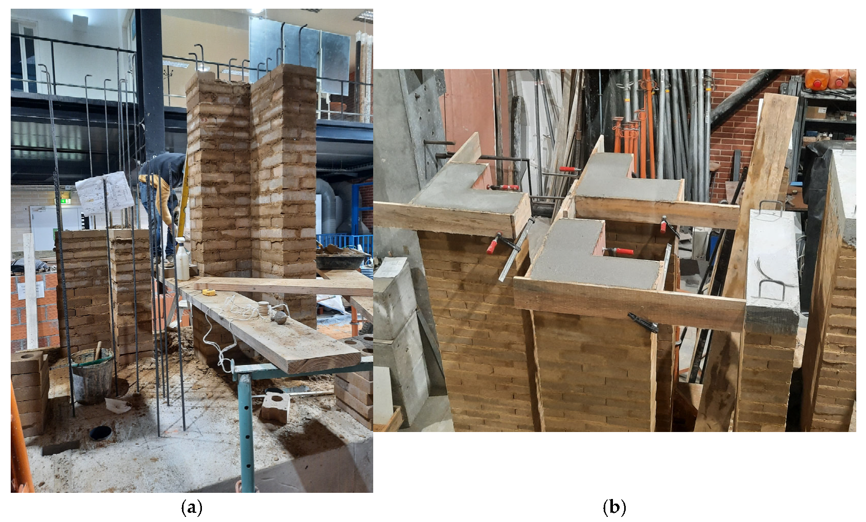
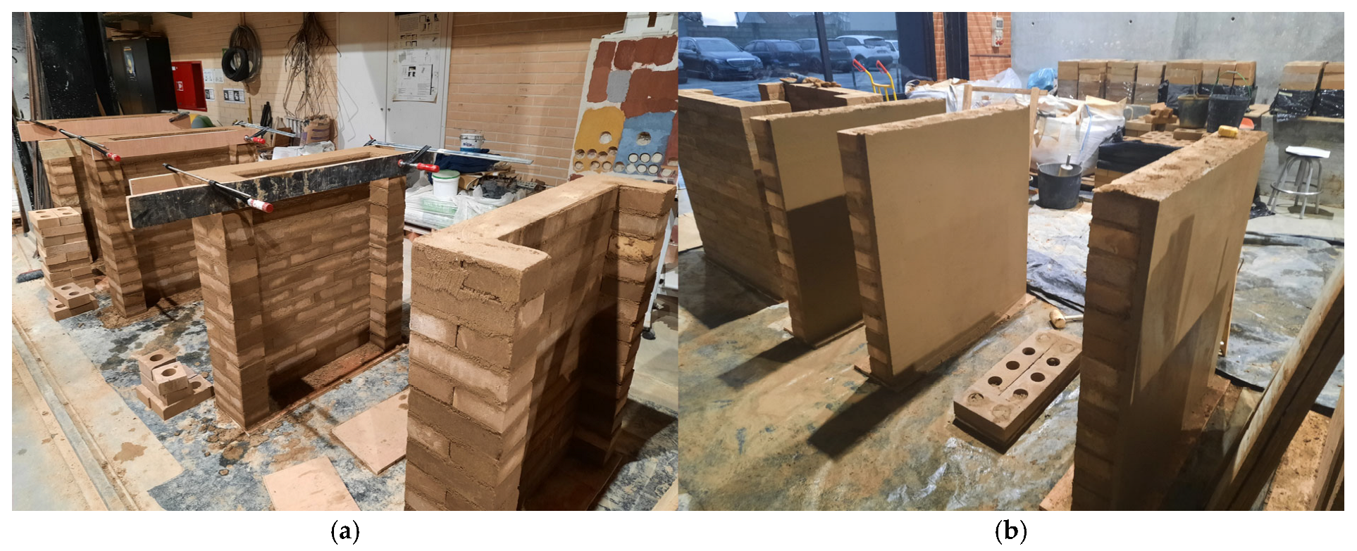
The specimens’ construction took place at UA’s Civil Engineering Laboratory in two stages and was carried out by 3 workers (2 professionals and 1 assistant).
All fifteen walls were nearly 220 cm high, with a reinforced 10 cm high concrete joist at the top to allow for effective horizontal load application. Testing full-scale specimens aimed at minimizing noise effects and behavioral distortions between components like reinforcements and masonry panels [11,52,53].
Twelve walls featured a pre-defined C-section with four designated for out-of-plane bending shear tests (Figure 9) and eight for in-plane cyclic bending shear tests (Figure 10). Additionally, three walls had a pre-defined non-plastered L-section (Figure 11).
The walls were constructed using vertical A500 steel bars of 10 mm diameter (placed in five filled holes for C sections and nine filled holes for L sections). Horizontal A500 steel bars of 6 mm diameter were installed at four levels, spaced 55 cm apart, starting from the top. All specimens were built on a reinforced concrete base, 60 cm in height, following a consistent design and material layout.
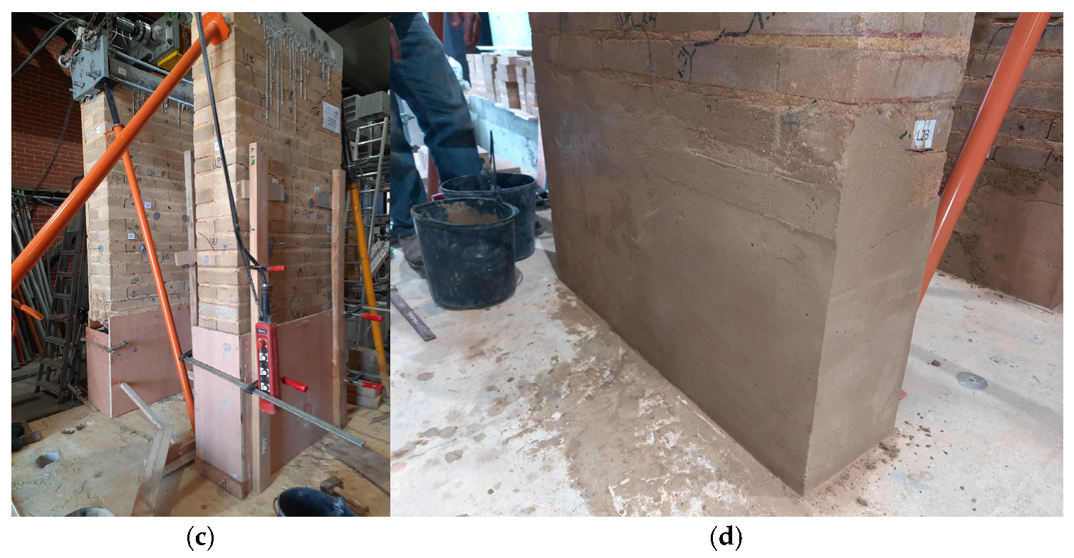
In addition, twelve wallets were built and tested in axial and diagonal compression, aiming to directly obtain mechanical properties under static loads. Specimens were also built to be used in strength tests on mortars and blocks, block absorption tests, and steel pullout tests, seeking to characterize the panels’ components (Figure 12).
The wallet specimens were built on mobile wooden bases and transported to the test site using a hydraulic jack, overhead crane, and a system of pulleys with manual hoists.

3.4.4. Test Systems’ Design and Assembly

According to the experiment groups mentioned in Section 3.4.1, two integrated test systems were designed and assembled:
  • System for Cyclic Bending Shear Tests on Full-Scale Walls.
  • System for Static Characterization Tests.
Development of System for Cyclic Bending Shear Tests on Full-Scale Walls
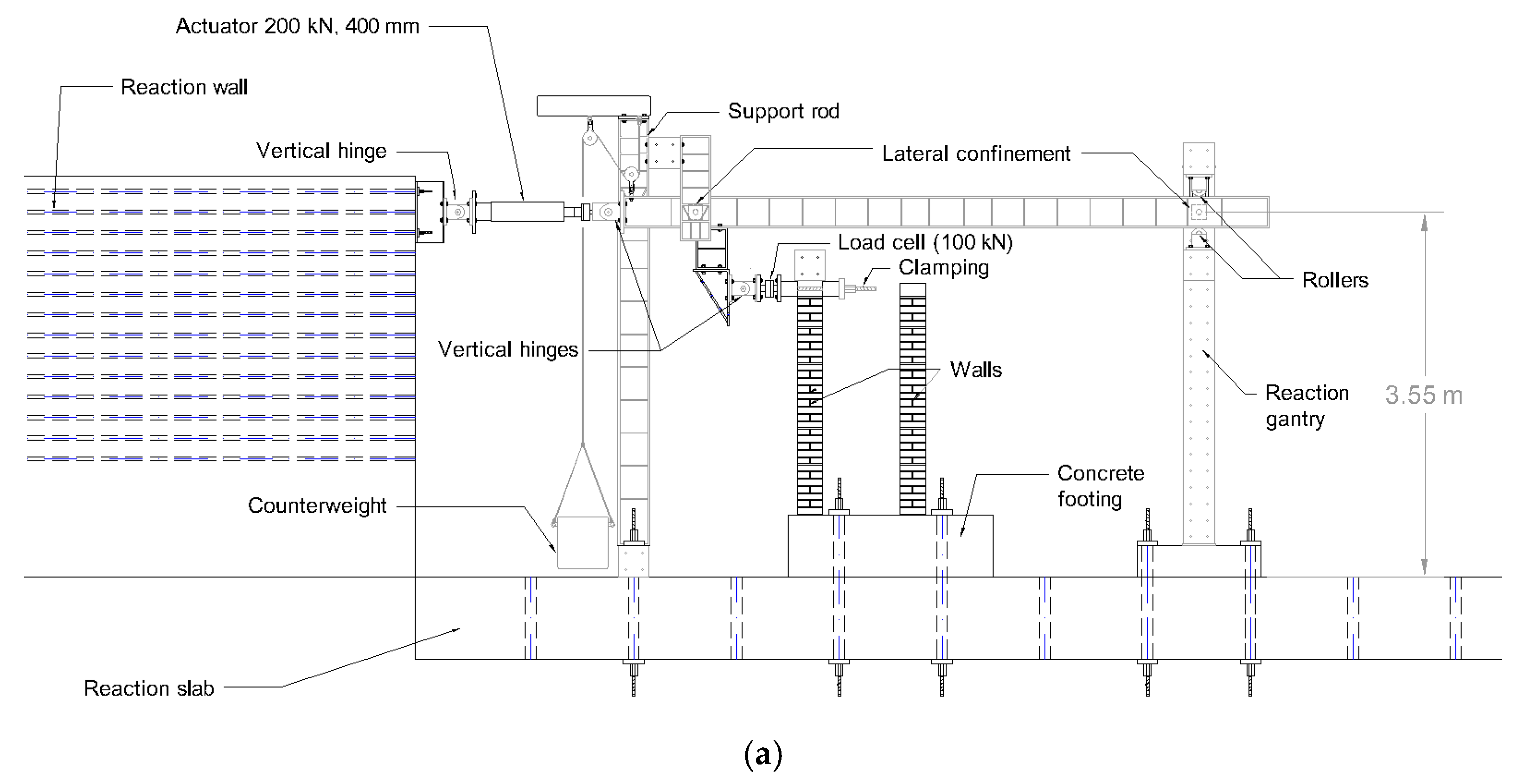
An innovative test system with a metallic structure, hinges, load cells, counterweight, and actuator next to a reaction wall was designed to carry out cyclic bending shear tests on full-scale masonry panels, whose detailed mechanism was explained in [49]. This system allowed for horizontal load application on top of the masonry panels located on reinforced concrete footings (Figure 13).
A mass next to 370 kg was applied on the top of the panels, representing an average roof’s permanent load. A footings’ movement system was also designed, which allowed footings to be moved and rotated for the purpose of applying the load at the panels’ top section geometric center.
The actuator was programmed to control displacement at a steady speed of 0.1 mm/s until a displacement of 5 mm was achieved. After that point, the speed was adjusted to 0.5 mm/s for in-plane bending shear tests and 1 mm/s for out-of-plane bending shear tests. Each load stage corresponds to three cycles, applied in four phases [54]:
  • Push configuration, phase 1/4 (positive displacements are increasing), and phase 2/4 (positive displacements are decreasing).
  • Pull configuration, phase 3/4 (negative displacements are increasing in absolute values), and phase 4/4 (negative displacements are decreasing in absolute values).
External LVDTs fixed on an independent support structure and aligned toward the specimens were used to measure both in-plane and out-of-plane displacements, as well as torsional rotations. Additionally, LVDT sensors were attached directly to the panels at four levels along their height, positioned to monitor steel deformations at specific locations.
Development of System for Static Characterization Tests
Part of the system for cyclic tests (the reaction gantry) was used for mechanical characterization tests under static loads.
The reaction gantry was fixed to the reaction slab using pre-tensioned bars, with the actuator fixed to the upper beam. For component testing, the actuator was programmed for automated displacement control, and for wallet compressive tests, the highest capacity actuator (1500 kN) was used in a manual control configuration.
In addition to the actuator sensors, the instrumentation included external LVDTs mounted on an independent support structure and directed toward the specimen to measure vertical displacements. Furthermore, LVDT sensors were attached to the wallets within a rectangular frame at specific locations aiming at monitoring steel deformations.

3.4.5. Carrying Out Experiments and Data Analysis

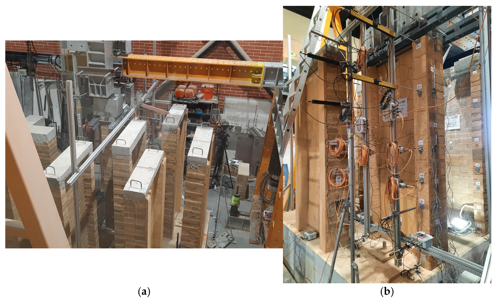
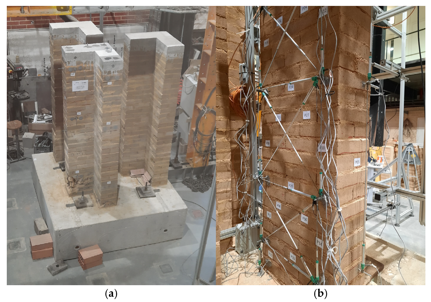
Cyclic bending shear tests and their instrumental frames can be visualized in Figure 14 (C-panels, out-of-plane), Figure 15 (C-panels, in-plane), and Figure 16 (L-panels).
The results were analyzed considering the technical standards corresponding to each test, using Matlab (versions 2020 and 2021a) and Excel (version Office Mondo 2016) software.

3.5. Panels’ Design Improvement

Based on the results obtained from the tests, it was possible to update the panels’ design, aiming to fix some observed problems and improve performance in real applications.

4. Results and Discussion

Starting from the initial panel’s design described in Section 3.1, the Results and Discussion Section will follow the same structure presented in Section 3.

4.1. Panels’ Introductory Experimental Study

4.1.1. Multifactorial Shear Experiment on Wallets

As this experiment is considered crucial for choosing the best panel typology, the quantitative results and analysis are presented below. Table 2 shows the individual maximum horizontal shear force results for the sixteen wallets that were tested at UFRJ.
Table 3 presents the main results from the multifactorial experiment. The color scale represents a visual output hierarchy, where the red represents the worst results, and the green, the best ones, for each criterion (effective shear force and house cost).
From a constructive point of view, practical experience shows that installing the reinforcements and the grout in the vertical holes is a laborious operation, as is anchoring the reinforcements in the foundations. Furthermore, it can be seen from Table 3 that there are configurations with sections partially grouted that present effective shear force factors very close to the factors of fully grouted panels. For this reason, it was decided to disregard the use of fully grouted panels.
Among the partially grouted panels, it can be noticed that the panel with two beams and with plaster presented high effective shear force factors (2.11 for seismic loads and 3.17 for non-seismic loads) and an increase in the house costs considered tolerable (34% for the traditional system and 32% for the ‘joint work’ system), so it was considered the most promising alternative. Furthermore, the panel configuration with two beams, partially grouted and without plastering, was also considered important to be investigated, as it would allow for strength gain (near 30%) with minimal impact on house costs.
Based on these results, it was defined that the experimental investigation would continue for panel configuration typologies with horizontal reinforcements approximately every 50 cm and partially grouted holes in the modalities with (2V.GP.CE) and without plaster (2V.GP.SE). In theory, this would allow residents to build the cheapest model (without plaster) at first and, in the future, add plaster to obtain performance gains.

4.1.2. Implications of Using Different Panel Types in SHS-Multirisk 1.0 House Model

The total calculated 1.0 house weight was 309.69 kN (64.47 kN for the roof and 245.22 kN for the walls with panel type 1V.GP.SE) [9]. Considering the different panels’ masses per area from Table 3, if one adopts the basic panel typology 2V.GP.SE, the total weight is near 64.47 kN + 245.22 kN × 231/220 = 321.95 kN. If the panel used is type 2V.GP.CE, the total estimated weight becomes 64.47 kN + 245.22 kN × 331/220 = 433.41 kN.
As detailed in [9], when applying the Equivalent Horizontal Force Method according to the Brazilian seismic standard NBR 15421 (2006) [55], the total horizontal force at the base is evaluated, in a given direction, according to the expression H = Cs∙W, where W represents the total permanent weight, and Cs is the seismic response coefficient associated with the pseudo acceleration Sa.
The calculated Equivalent Horizontal Forces for the same seismic scenarios studied in [9] (PGA 0.2 g and 0.5 g, for soil types A—healthy rock, B—rock, C—altered rock or very rigid soil, D—rigid soil, and E—soft soil) are present in Table 4 for the house weights corresponding to different panel typologies.
Following the same steps and criteria detailed in [9], structural verifications in the SHS-Multirisk 1.0 house model with the new panel typologies were carried out for the ultimate limit state. These verifications were based on BS 5628-2 (2005) [56] with adaptations when necessary, and considered walls as isolated, conservatively ignoring the group effect.
It is worth noting from Table 4 that, when using the appropriate basic panel’s typology (1V.GP.SE for scenarios 1–4, 2V.GP.SE for scenarios 5–7, 2V.GP.CE for scenarios 8–9), the SHS-Multirisk 1.0 model appears to be technically feasible regarding in-plane shear behavior. However, some localized problems appear in bending for more aggressive scenarios (5–9) and panels at the edges revealed critical stress, which has what motivated the strengthening of these regions in SHS-Multirisk 2.0 house model.
These results confirmed the interest in typologies 2V.GP.SE and 2V.GP.CE for house model 2.0 panels.

4.2. Panels’ Design Review

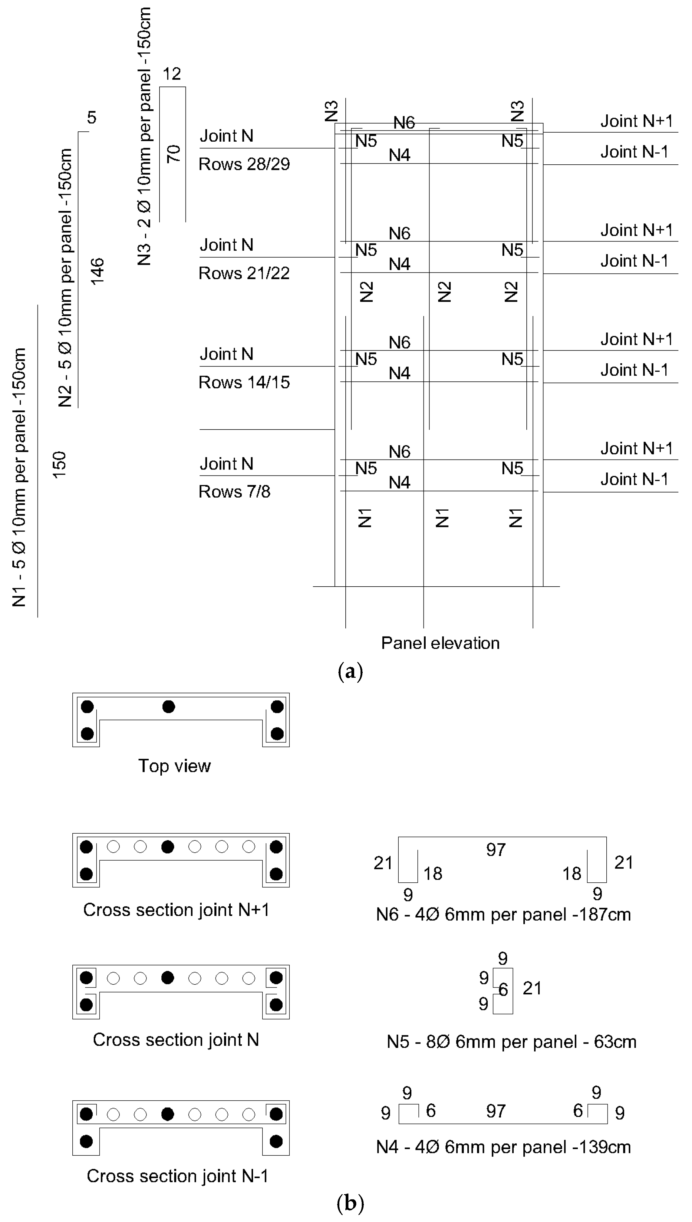
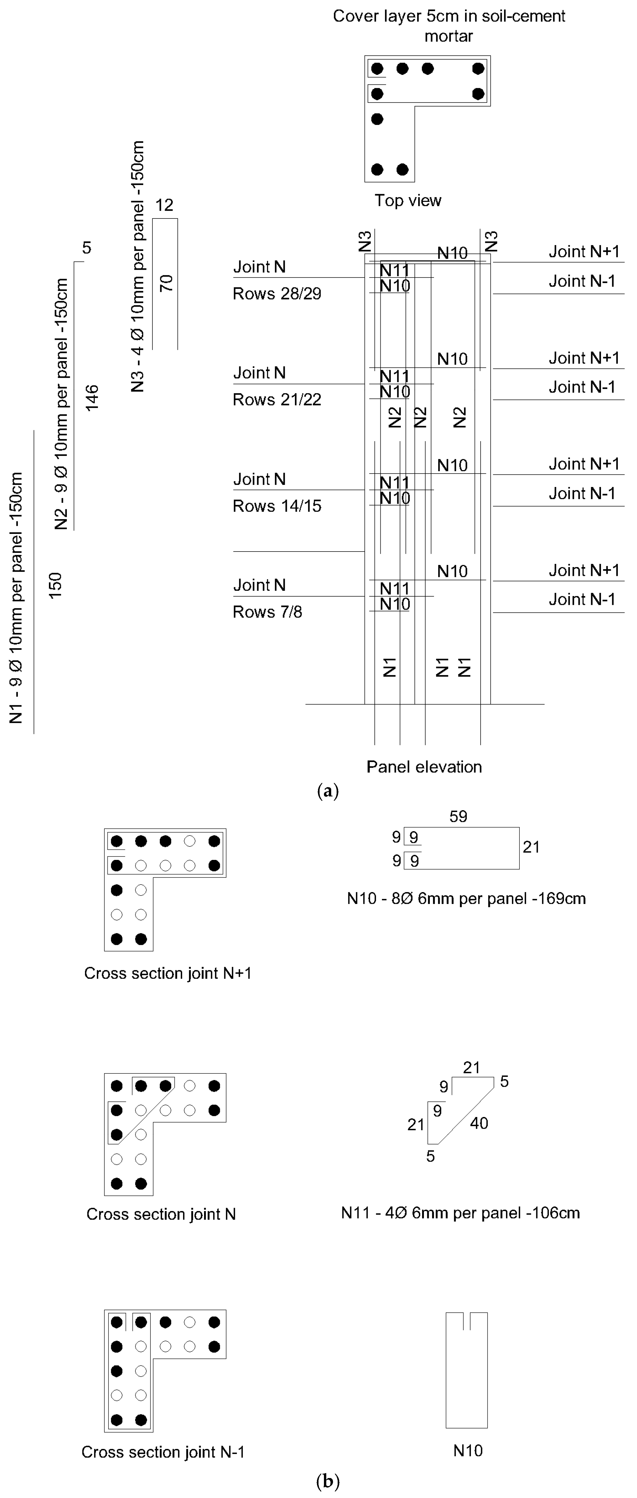
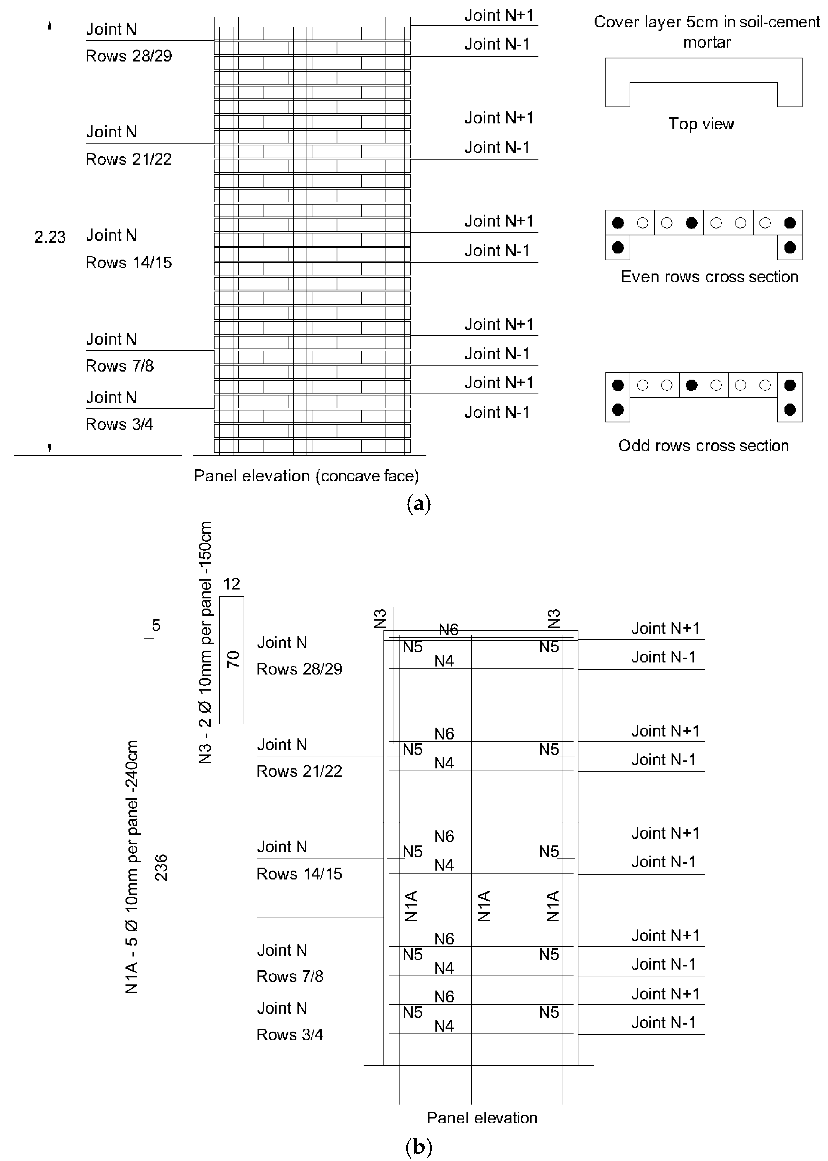
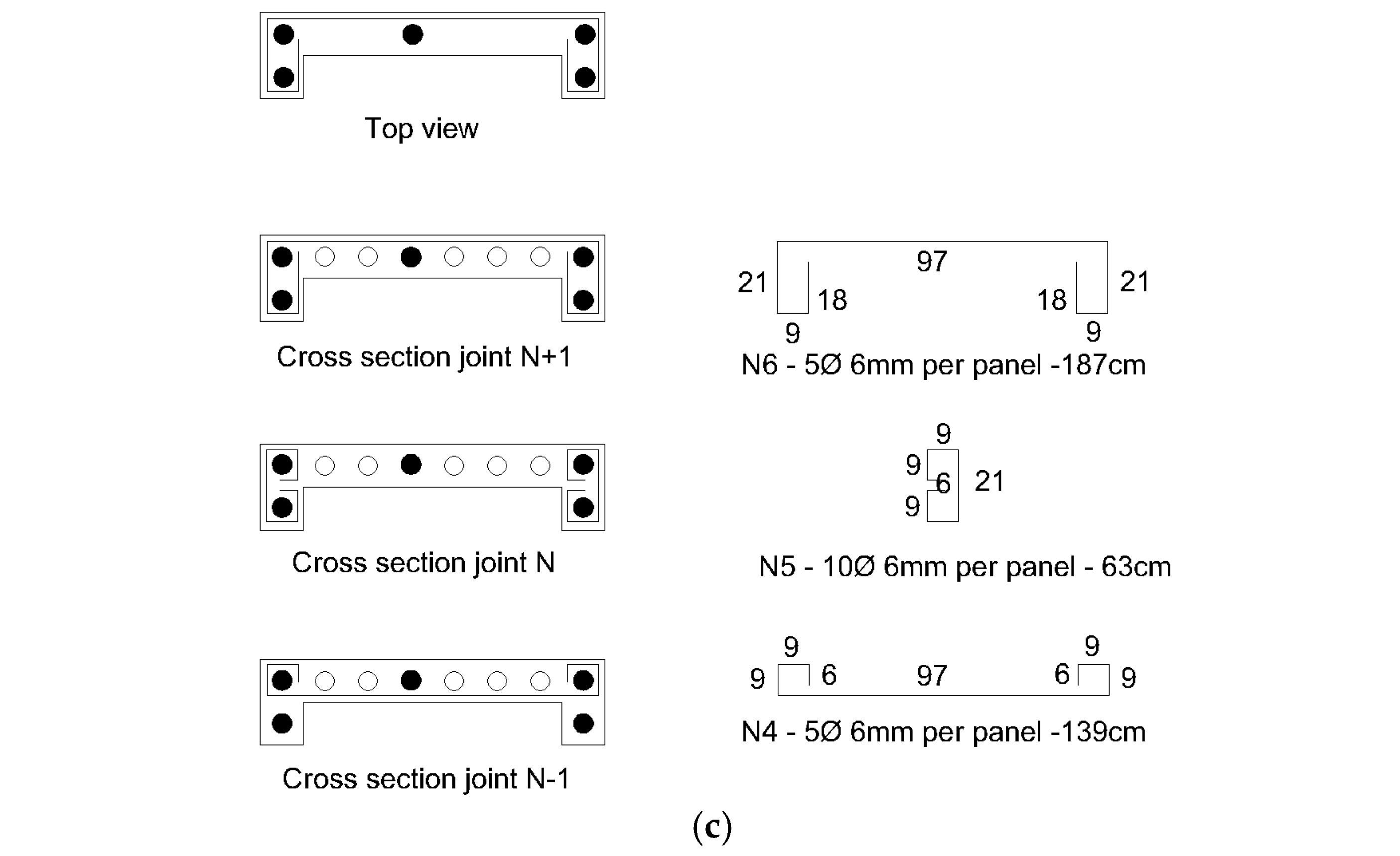
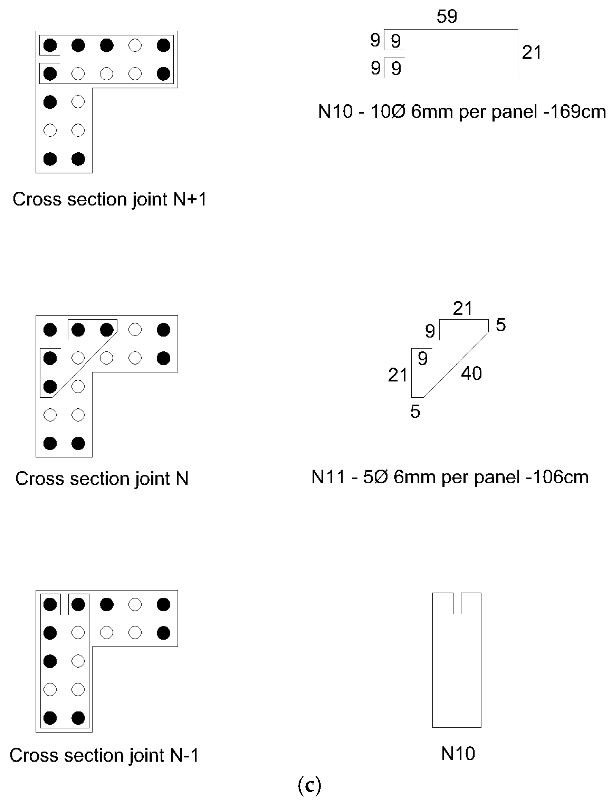
Starting from the preliminary design presented in Section 3.1, Figure 17 and Figure 18 illustrate the executive design of panels C and L, respectively. An overlapping length of 55 cm was adopted in the vertical Ø10 mm bars. The horizontal reinforcements of Ø6 mm were organized as sets of three pieces, so no reinforcements were crossing in the mortar joints with an average thickness of 10 mm.

4.3. Panels’ Main Experimental Study

4.3.1. Key Experiment Outputs

The focus of this article is not to discuss quantitatively the experiments’ results, but rather to describe the overall panels’ development process and their preliminary relation to house performance, especially regarding in-plane simple shear and bending shear behavior. However, there are key findings that are useful to understand the 2.0 house’s performance, which will be presented in the following sections. Additional quantitative experimental results can be found in [57,58].
Results from Static Diagonal Compression Tests at UA
Long et al. [59] emphasize the importance of cohesive models and parametric studies to understand the mechanical properties of materials under dynamic loading. In this regard, attempts were made to parametrize some findings by comparing the results obtained in Brazil and in Portugal.
Table 5 contains the main wallet diagonal compression test results, as well as the equivalent pushover horizontal forces, calculated from the specimens’ geometry.
One can note that the values of maximum shear forces obtained in Portugal diverged significantly from the results obtained in Brazil. Plastered wallets had an average force of 124.55 kN in UA’s tests, near 2.19× the average of 56.87 kN obtained at UFRJ. In the same direction, non-plastered wallets had an average force of 70.30 kN in UA’s tests, near 2.86× the average of 24.55 kN obtained at UFRJ.
While [58] reported an average compressive strength of 5.17 MPa for the blocks used in UA tests, [9] mentioned an average value of 2.06 MPa for blocks manufactured for wallet tests in Brazil (nearly 2.51× higher). Additionally, the mortars used in Brazil presented a compressive strength of 4.44 MPa, while those in Portugal revealed an average of 11.70 MPa (also nearly 2.64× higher).
These results suggest that the increase in the wallets’ shear strength was probably due to the increased blocks and mortars’ strengths, since the percentage gains in the components’ compressive strength were similar to the percentage increases in shear strength. It is believed that the determining factors for the increased strength in the components manufactured in Portugal were the type of soil used, the curing process under more appropriate conditions, and the type of machine used to press the blocks. It should also be noted that the tests on the components at UA were carried out for periods much longer than 28 days from manufacturing, and there may have been some residual resistance gain over time.
Results from Full-Scale Panels’ In-Plane Bending Shear Tests
According to [58], the designed panels showed good shear deformation capacity at in-plane and out-of-plane conditions, what contributes to their applicability at contexts with high horizontal loads, such as those that occur in earthquakes and hurricanes; ref. [57] demonstrated that the panel frequencies were within the expected range.
The qualitative results from the main experiments also provided significant information for understanding the panels’ behavior and allowed the sufficient conditions to determine the panels’ improvement. The most relevant points are as follows:
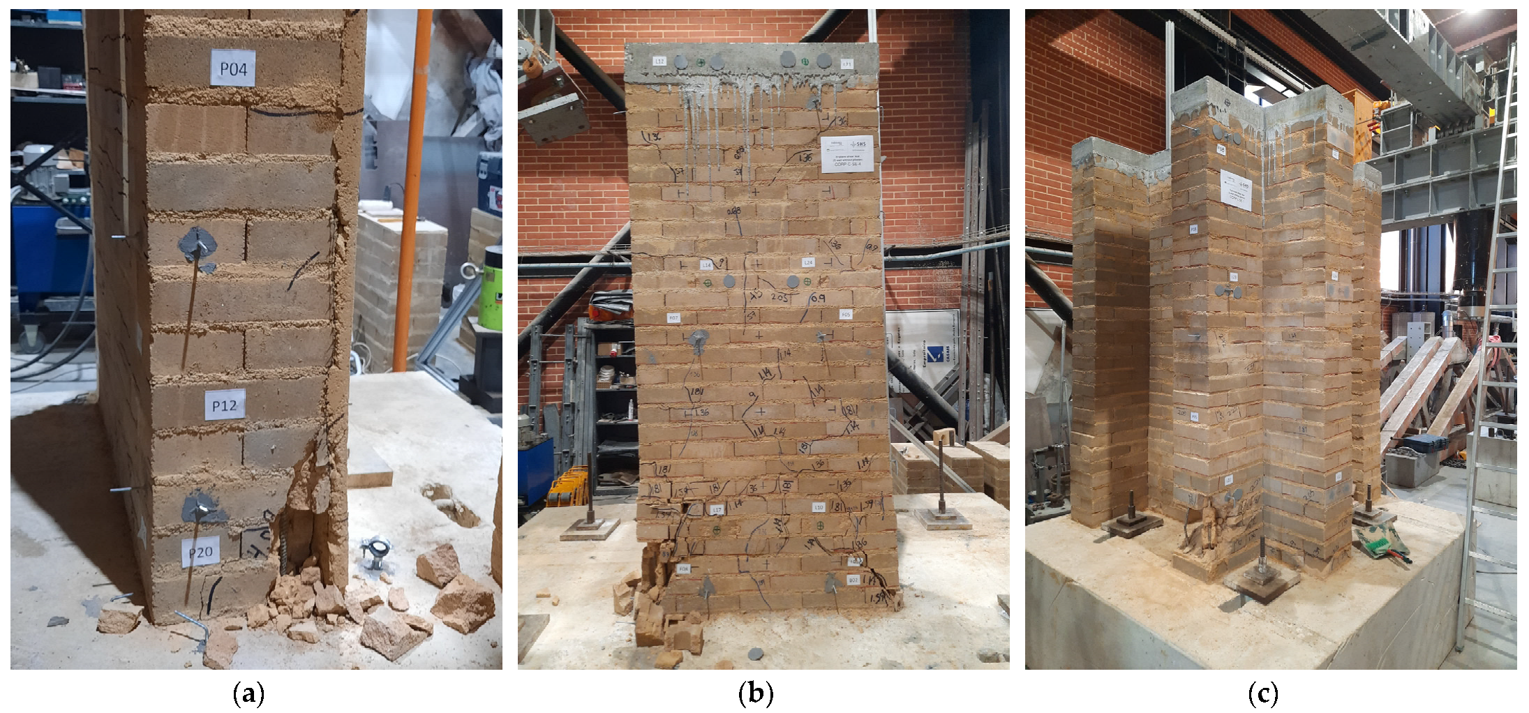
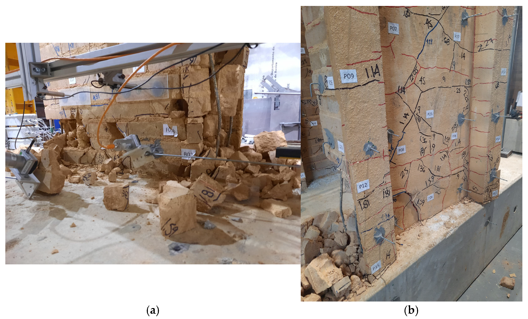
  • In all panels that kept vertical reinforcement active, collapsing occurred by the blocks’ compression at the base, revealing that the bending effect is critical to the structural panels’ performance under cyclic loads (Figure 19).
  • In addition to the blocks’ compressive collapse, it was observed that the high plastic stretching at the base bars increased buckling when compressed, contributing to the base blocks’ damage (Figure 20). This observation led to the decision to reinforce the horizontal bars at the panel’s low quarter, shortening the spaces between the steel stirrups.
  • When vertical reinforcement remained active, the arrangement between the vertically grouted holes and the steel stirrups were successful in keeping the panel’s integrity during the cyclic tests, even if some mortar layers slightly slipped.
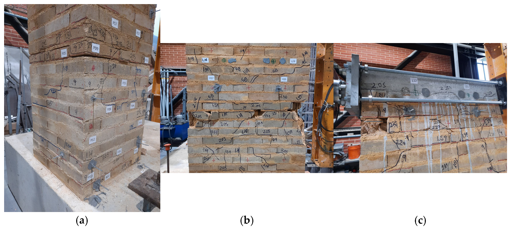
  • In 2/3 of the L-panels, the lap splices did not work effectively, while this happened in apparently 3/8 of the C-panels tested under cyclic in-plane shear with bending (Figure 21). This was attributed to the more prominent torsional behavior and to the shorter distance between the reinforcements and the compressed section in the L-panels, what increases the forces at the bars under bending stress, when compared to the C-panels. This observation led to the decision to adopt vertical entire bars, instead of using lap splices.
From a quantitative point of view, the maximum forces obtained in the cyclic bending shear tests are particularly useful for a structural verification based on the Equivalent Horizontal Force Method (EHFM), according to the Brazilian seismic standard NBR 15421 (2006) [55] (Table 6).
It is worth noting from Table 6 that the average in-plane bending shear capacity of the panels with plaster (CE) is just 8% higher than that of panels without plaster (C). This may contrast with the results from the diagonal compression tests, in which wallets with plaster showed to be 77% more resistant than wallets without plaster (Table 3). One can also calculate efficiency factors (EFs) between in-plane bending shear against simple shear, obtaining 0.451 for C-panels without plaster, 0.275 for plastered C-panels, and 0.360 for non-plastered L-panels, revealing that simpler panels may be more efficient (and cheaper to build).
Indeed, it is now clear that this drop in shear resistance is due to the bending behavior in full-scale panels, what is totally in accordance with the results from the structural verifications carried out in Section 4.1.2 for the 1.0 house model.

4.3.2. Implications of Using Proposed Panel Types in SHS-Multirisk 2.0 House Model

To carry out preliminary capacity verification for the house model 2.0, we will choose the border panel lines (lateral ones), since we have in-plane bending shear experimental data for all the panels’ typologies in this direction. The total horizontal force at the panels’ line is evaluated according to the expression Hline = Cs∙Wline, where Wline represents the total permanent weight at the line, and Cs is the seismic response coefficient associated with the pseudo acceleration Sa.
Adopting a simplified and conservative approach, the panels’ out-of-plane bending shear capacities and group effects were disregarded. Thus, the panels’ line service capacity (LSC) was calculated by summing the individual panels’ capacities obtained from the experiments. The roof weight was assumed to be the same as in model 1.0 (64.47 kN), since the houses have similar areas. However, a 25% share was considered for the panel line studied, proportional to its influence area. Horizontal loads from the earthquake’s effects on the roof were distributed proportionally to the panels’ in-plane bending inertias. The water tank load was not considered acting on this line, since in model 2.0, it is the bunker panels that directly support it.
In addition to the roof and self-weight panels’ load, it was also assumed that each panel supports half the load of another nearby transverse panel when seismic loads occur. The properties for different panel typologies are summarized in Table 7, while the properties of the panel lines for the plastered and non-plastered configurations are summarized in Table 8.
Both house models’ masses are very close (310 kN in model 1.0, 311 kN in model 2.0 with panels without plaster, and 342 kN in model 2.0 with plastered panels), the materials are essentially the same and the height is also similar. Therefore, similar house frequencies are expected and the same response spectra values will be adopted for both models.
Since Cs is the seismic response coefficient, defined as Cs = (2.5 ags0/g)/(R/I), where ags0 corresponds to the spectral acceleration for the period 0.0 s and I is the importance factor corresponding to the use of the structure, the only difference between the house models 1.0 and 2.0 is in the response modification coefficient (R), which is related to the basic earthquake-resistant system. In model 1.0, the system was classified as ‘porticos that resist at least 25% of seismic forces and masonry walls with common reinforcement (ASCE 7-05)’ in which R = 3.0, whereas in model 2.0, the most appropriate system seems to be ‘inverted pendulum-type structures and cantilever column systems’, in which R = 2.5. This means that one can obtain Cs for model 2.0 (Cs,2.0) by simply multiplying the original parameter by the factor 3.0/2.5, due to the difference in the R parameter.
After calculating the Horizontal Equivalent Force for the panel’s line, the global safety factor (GSF) can be obtained by dividing LSC by Hline.
The global safety factors obtained in Table 9 and Table 10 illustrate the panels’ performance in lines type 1 and 2, respectively. It is interesting that the line with panels with no plaster have slightly higher GSF for all seismic scenarios and for all scenarios GSF > 3, that is, the panels would withstand stress, in service conditions, by a comfortable safety factor.
It also demonstrates that, solely from the forces’ perspective, the favorable effect of the plaster at the panels’ in-plane bending shear resistance may be surpassed by the adverse effect of mass increasing. This leads to the conclusion that simpler panels may perform better than plastered ones in full-scale walls, mainly due to bending effects. Despite that, we believe that using a polyethylene mesh within a very thin plaster layer (<1 cm thick only in the internal side) can be useful in increasing the panels’ performance for bending shear.
Another noteworthy point is that the discussion in the Section Results from Static Diagonal Compression Tests at UA revealed that the wallets’ shear performance is directly conditioned by the components’ resistances. The same applies to the findings in Section Results from Full-Scale Panels’ In-Plane Bending Shear Tests, where efficient factors were obtained between in-plane bending shear against simple shear. Despite the fact that this topic deserves future investigations with wider samples, we will adopt these relations as valid for estimating the bending shear resistance of panels with components of minimum strengths (this is the case for the tests at UFRJ) using two equivalent methods (Table 11):
  • M1 (based on the resistance factors calculated in Section Results from Static Diagonal Compression Tests at UA): For similar situations where the components’ strengths are 2.51× lower than the ones obtained at UA, it is expected that the bending shear behavior will be 2.19× lower for plastered panels and 2.86× lower for non-plastered ones.
  • M2 (based on the bending shear efficiency factors calculated in Section Results from Full-Scale Panels’ In-Plane Bending Shear Tests): In this option, the hypothesis is that the efficiency factors (0.451 for C-panels without plaster, 0.275 for plastered C-panels, and 0.360 for non-plastered L-panels) may be similar independently of the components’ resistances, so that applying these factors to the average shear forces obtained in UFRJ wallet tests would allow for obtaining bending shear estimations for full-scale panels with minimum resistance components.
The corresponding reduced line service capacity can be found in Table 12.
Finally, even for panels constructed with components of minimum strengths prescribed in the standards, these findings reveal that the global safety factor is greater than 1 for all seismic scenarios studied in this preliminary analysis (Table 13 and Table 14), suggesting the panels would withstand in bending shear service conditions.
Although this approach has limitations inherent to the EHFM, the real load corresponding to the accelerations acting on the panels’ masses (near 80% if the total seismic load) would act distributed along the panels’ height and not concentrated at the top, which is what occurred in the cyclic tests. This means that, in real seismic situations, the bending moments at the base would be reduced by 50% × 80% = 40%, allowing an increase in simple shear behavior and probably increasing the safety factors. In this context, plastered panels may have greater safety factors than non-plastered ones.

4.3.3. Aspects Regarding Panels’ Deformation Capacity

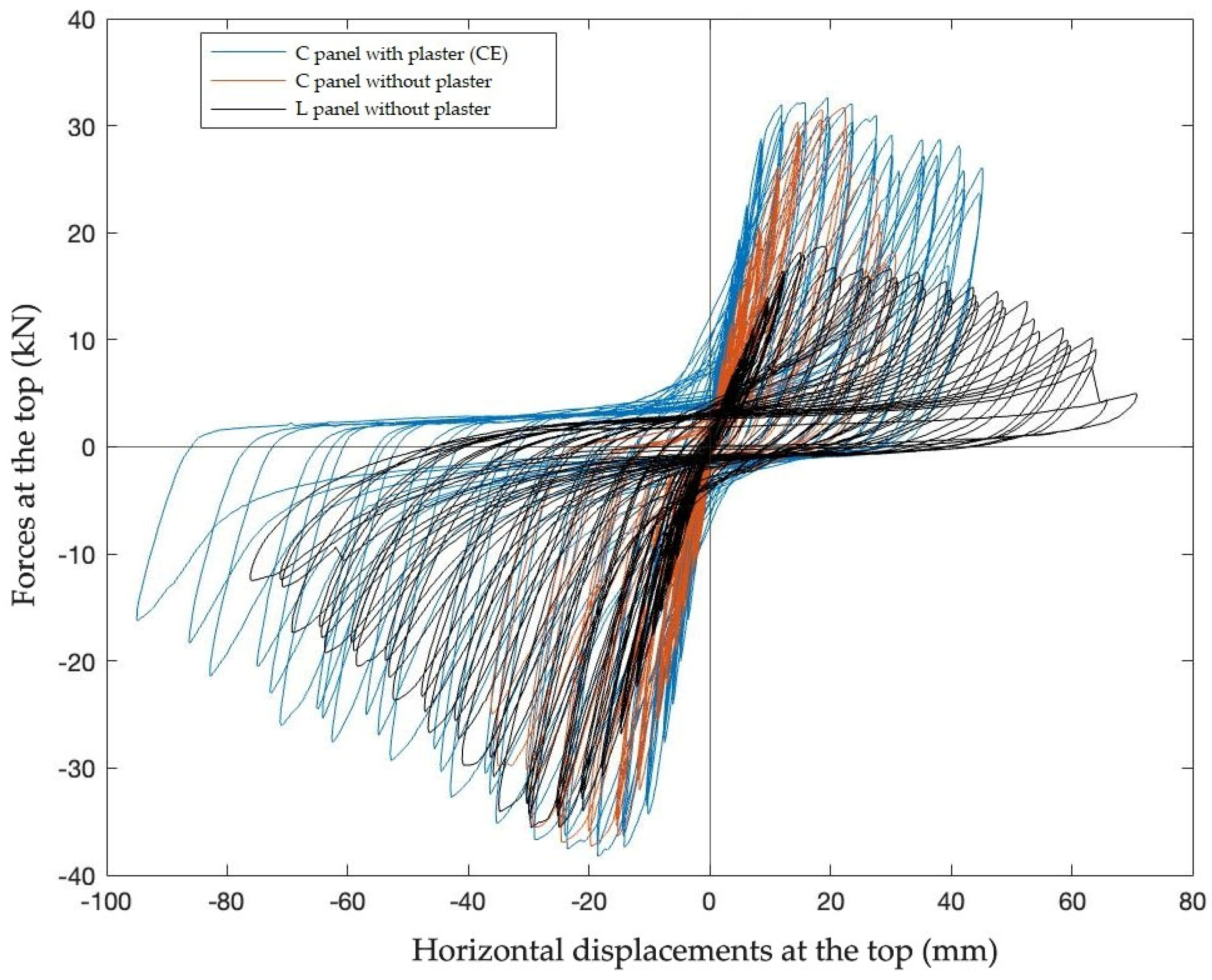
An assertive quantitative analysis for the cyclic bending shear panels’ properties and behavior demands more in-depth analysis of data, experimental details, and mechanisms that are out of the purpose of this paper. However, to provide a general overview of different panel types in-plane bending shear behavior, the cyclic load x displacement graphs for three representative specimens are presented in Figure 22.
From Figure 22, it is possible to note the following for in-plane bending shear:
  • Despite the maximum forces are similar, C plastered panels allow for greater displacements than non-plastered ones, revealing more ductility and better stability in critical damage conditions. This characteristic is very useful in seismic contexts, what confirms C plastered panels as a resilient option.
  • L-panels also presented good deformation capacity, but due to their asymmetric geometry, the force behavior in pulling is very different from pushing. However, as they act in opposite pairs within the panel lines, the load asymmetry effect may be reduced. These panels presented a more prominent stiffness degradation rate when the tensioned region was within the panel’s width (and the compressed region was within the panel’s length).
  • For all panels in which the steel bars remained working, high displacements were achieved.
It is important to highlight that none of the panels collapsed during or after the cyclic tests. Even when critically damaged and disconnected from the test system, all panels continued supporting the roof simulated load and the self-weight. Despite the reinforcements being plastically deformed, they had an important role in this ultimate performance.

4.4. Panels’ Design Improvement

As mentioned in the previous section, after the cyclic tests, it was concluded that the vertical reinforcements should preferably be continuous, without splices. While this may represent some additional construction work, it is understood that the level of reliability in panels’ performance can be improved significantly. Even so, more care is needed with the consolidation of the mortar in the holes, and it should have a more fluid consistency.
As the collapse at the panels’ bases was associated with the buckling of the reinforcements, it was necessary to add two stirrups in the panels’ lower frame (first 50 cm from the base) to reduce the bars’ buckling length.
Figure 23 and Figure 24 contain the final panels’ design version.
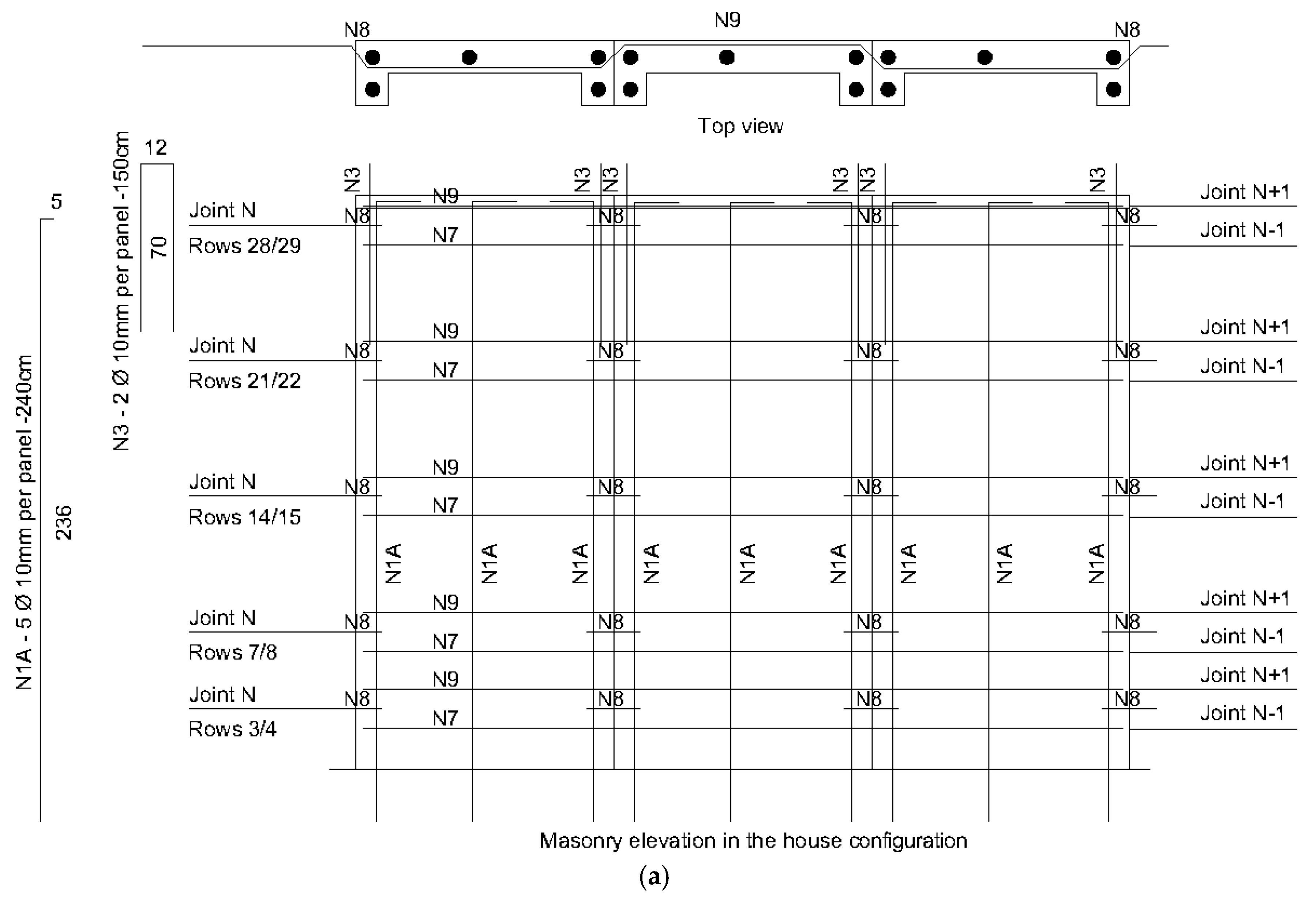
Figure 25 contains the panels’ integration into the house walls. As one can see, the panels should be constructed keeping vertical joints but providing horizontal reinforcements that allow solidary out-of-plane displacements.

4.5. Panels’ Recovery Process

Two C-panels (one with plaster and the other without plaster) were then recovered with the reinforcement’s insertion and tested again. The recovery process was based on the following steps (Figure 26):
  • Pre-shoring of walls;
  • Wall’s horizontal alignment at the base;
  • Wall’s vertical alignment;
  • Locking struts in the wall right position;
  • Replacing/welding of broken bars;
  • Adding new steel bars where buckling occurred;
  • Wooden formwork to cast mortar;
  • Pouring soil/cement mortar into the forms;
  • Mortar wet curing for 3 days;
  • Removal of forms after 7 days;
  • Removal of metal props after 28 days.
Both recovered walls presented restitution of the load capacity in the final displacements in at least one of the test directions (pulling and/or pushing). This result confirms that it is possible to recover panels critically damaged using simple techniques and local resources, restoring their work capacity. This is particularly useful to prevent the corrosion of exposed steel bars and structural deterioration in damaged and cracked walls, as mentioned by Zhang et al. [60].
The panels; ductility is a critical feature for seismic resilience. Vertical reinforcement enhances ductility, while the modular design ensures post-damage recoverability, allowing individual panels to be recovered after critical damage. Kennedy [61] emphasized the importance of conservative strain limits to prevent failure, but SHS findings indicate that the panels can maintain functionality after significant damage and recovery.
This feature is particularly valuable in disaster-prone regions, where rapid reconstruction is essential.

5. Conclusions

The SHS-Multirisk 2.0 house development process involved several complexities, especially regarding the panels’ development.
The complexities originated from several aspects, such as the different dynamics of the loads arising from earthquake and hurricane hazards, the high degree of interdependence between house and panels’ designs, the interdisciplinarity between architectural design and engineering performance, and the need to use local materials with reduced environmental impact and artisanal production techniques, in accordance with the project’s philosophy of simplicity.
From a construction point of view, the development objectives were considered to be achieved, since it was possible to manufacture the blocks with local materials and without electric power. Furthermore, the panels were built manually by professionals who had never worked with this technology, proving their viability for use by local populations.
From a technical point of view, the objectives were also considered to be achieved in the panels’ design. The designed panels showed good performance in bending shear, especially for in-plane conditions, demonstrating their applicability in seismic contexts (see Video S1 at the Supplementary Materials section at the end of this paper). C plastered panels revealed better performance than non-plastered ones for high displacements, but this good performance depends on the effectiveness of a structured mesh (i.e., polyethylene) embedded in a thin mortar layer. Despite the fact that the structured plaster’s role in shear is remarkable, bending restrictions may significantly limit this advantage. L-panels have accelerated stiffness degradation when compared to C-panels.
Preliminary assessments based on the Horizontal Equivalent Force (HEF) method prescribed by NBR 15421 [55] and BS 5628-2 [56] revealed that by using the adequate panel types as tested in the UFRJ multifactorial experiment, the SHS-Multirisk 1.0 house model would attend shear ultimate limit state requirements for load scenarios PGA 0.2 g (terrains classes A, B, C, D, E) and PGA 0.5 g (terrains classes A, B, C, D), but bending remains unattended. However, in real service conditions for scenarios like the Haiti 2018 and 2010 earthquakes, model 1.0 would probably perform satisfactorily.
Starting with the results of the bending shear cyclic tests carried out at UA, introductory assessments for the SHS-Multirisk 2.0 house model allowed for estimating HEF loads and comparing them to the border panel’s line’s service bending shear capacity. The global safety coefficients were revealed to be greater than 3 for all studied scenarios, pointing towards successful performance for seismic situations. Furthermore, the damaged panels could be recovered using simple techniques, with much of their deformation capacity being restored after recovery.
From the point of view of an R&D&I design, it is considered that the objectives were adequately achieved, since they include the research, development, and practical implementation of the following products and processes: SHS-Multirisk 2.0 house panels (fully developed products), system for full-scale wall cyclic testing (complete product), process for full-scale wall cyclic testing (complete process), and the SHS-Multirisk 2.0 house (product under development through the UFRJ-UA partnership).
The main limitation of this work has to do with the local materials’ varying properties, the differences in the machines eventually used to manufacture the blocks, and the differences in personnel expertise employed in the panels’ construction, based on different contexts, cultures, and locations. However, an attempt was made to estimate the cyclic bending shear’s service capacity for panels constructed with minimum strength parameters. In this case, the global safety coefficients for the border panel lines revealed greater than 1 for all scenarios studied, indicating probable successful performance in scenarios like the Haiti 2018 and 2010 earthquakes.
While the present research has demonstrated the feasibility of obtaining effective local construction solutions for SHS Project situations, it is important to highlight that further data analysis, computational modeling/simulations, and verifications must be carried out to develop a definite comprehensive understanding of the full house model’s performance in diverse seismic contexts.
The house model is still an object of investigation through the collaboration of UFRJ-UA, which aims to understand the hazard scenarios to which the house is applicable.

Supplementary Materials

The following supporting information can be downloaded at: https://www.mdpi.com/article/10.3390/buildings15173242/s1, Video S1: SHS Test System (2022).

Author Contributions

Conceptualization, L.D.G., A.C., A.T., H.R. and J.F.; methodology, L.D.G., A.C., A.T., H.R., J.F., G.G., A.H., F.D. and G.J.; software, L.D.G. and J.F.; validation, L.D.G., A.C., A.T., H.R., J.F., A.H., G.G., F.D. and G.J.; formal analysis, L.D.G., A.C., A.T., H.R. and J.F.; investigation, L.D.G., A.C., A.T., H.R., J.F. and G.G.; resources, L.D.G., A.C., A.T., H.R., A.H., F.D. and G.J.; data curation, L.D.G., J.F. and G.G.; writing—original draft preparation, L.D.G.; writing—review and editing, L.D.G., A.C., A.T., H.R., J.F., G.G., A.H., F.D. and G.J.; visualization, L.D.G., A.C., A.T., H.R., J.F., G.G., A.H., F.D. and G.J.; supervision, L.D.G. and A.C.; project administration, L.D.G. and A.C.; funding acquisition, L.D.G., A.C., A.T., H.R., A.H., F.D. and G.J. All authors have read and agreed to the published version of the manuscript.

Funding

This research was funded by the Federal University of Rio de Janeiro and the University of Aveiro. This work was also supported by the Foundation for Science and Technology (FCT)—Aveiro Research Centre for Risks and Sustainability in Construction (RISCO), Universidade de Aveiro, Portugal [FCT/UIDB/ECI/04450/2020]. Jorge Fonseca acknowledges the Foundation for Science and Technology (FCT) for the PhD grant, with reference 2022.13794.BD. Alice Tavares is grateful for the financial support of the project CICECO-Aveiro Institute of Materials, UIDB/50011/2020, UIDP/50011/2020 and LA/P/0006/2020 and DOI 10.54499/2021.03830.CEECIND/CP1659/CT0032 financed by national funds through the FCT/MCTES (PIDDAC).

Data Availability Statement

Research data may be available under reasonable request.

Acknowledgments

The authors acknowledge the Civil Construction Department of the Polytechnic School of UFRJ for the financial support in the blocks’ manufacture and construction of the specimens; the UA’s Civil Engineering Department for the use of lab facilities; the CompanyVagoinertes, LDA. for the provision of soil, water, electricity, and storage.

Conflicts of Interest

The authors declare no conflicts of interest. The funders had no role in the design of the study; in the collection, analyses, or interpretation of the data; in the writing of the manuscript; or in the decision to publish the results.

References

  1. Centre for Research on the Epidemiology of Disasters (CRED). 2023: Disasters in Numbers, 1st ed.; UCLouvain: Brussels, Belgium, 2024. [Google Scholar]
  2. Cutter, S.L.; Boruff, B.J.; Shirley, W.L. Social vulnerability to environmental hazards. Soc. Sci. Q. 2023, 84, 242–261. [Google Scholar] [CrossRef]
  3. UN-Habitat. World Cities Report 2020: The Value of Sustainable Urbanization, 1st ed.; United Nations Human Settlements Programme: Nairóbi, Kenya, 2020. [Google Scholar]
  4. Tierney, K. The Social Roots of Risk: Producing Disasters, Promoting Resilience, 1st ed.; Stanford University Press: Redwood City, CA, USA, 2014. [Google Scholar]
  5. Okuyama, Y. Disaster impact and input–output analysis. Econ. Syst. Res. 2019, 31, 178–193. [Google Scholar] [CrossRef]
  6. Norris, F.H.; Stevens, S.P.; Pfefferbaum, B.; Wyche, K.F.; Pfefferbaum, R.L. Community resilience as a metaphor, theory, set of capacities, and strategy for disaster readiness. Am. J. Community Psychol. 2008, 41, 127–150. [Google Scholar] [CrossRef] [PubMed]
  7. Aldrich, D.P. Building Resilience: Social Capital in Post-Disaster Recovery, 1st ed.; University of Chicago Press: Chicago, IL, USA, 2012. [Google Scholar]
  8. Aydin, M.C.; Işık, E.; Büyüksaraç, A.; Ulu, A.E.; Avcil, F. Technical and Socio-Economic Perspective on the Disaster of the Century (6 February 2023 Earthquake) in Türkiye on the Second Anniversary. Geol. J. 2025, 1–18. [Google Scholar] [CrossRef]
  9. Di Gregorio, L.; Guimarães, G.; Tenório, M.; Lima, D.; Haddad, A.; Danziger, F.; Jannuzzi, G.; Santos, S.; Lima, S. The Potential of CEB Reinforced Masonry Technology for (Re)construction in the Context of Disasters. Materials 2020, 13, 3861. [Google Scholar] [CrossRef]
  10. Houben, H.; Guillaud, H. Earth Construction: A Comprehensive Guide, 1st ed.; Intermediate Technology Publications: Rugby, UK, 1994. [Google Scholar]
  11. Vintzileou, E. Testing Historic Masonry Elements and/or Building Models. In Perspectives on European Earthquake Engineering and Seismology; ANSAL, A., Ed.; University Istanbul: Istanbul, Türkiye, 2014; Volume 1, pp. 267–307. [Google Scholar]
  12. Magenes, G.; Calvi, G.M. In-plane seismic response of brick masonry walls. Earthq. Eng. Struct. Dyn. 1997, 26, 1091–1112. [Google Scholar] [CrossRef]
  13. Di Gregorio, L.; Guimarães, G.; Danziger, F.; Jannuzzi, G.; Qualharini, E.; Veról, A.; Haddad, A.; Miguez, M.; Cruz, V.; Bianchessi, D. Simple Housing Solution Project: (Re) Building in Critical Situations. In Natural Hazards—Impacts, Adjustments, and Resilience, 1st ed.; Farsangi, E.N., Ed.; IntechOpen: London, UK, 2021; Volume 1, pp. 1–22. [Google Scholar] [CrossRef]
  14. SHS—Solução Habitacional Simples/Simple Housing Solution. Available online: https://shs.poli.ufrj.br/ (accessed on 29 August 2025).
  15. UNDRR—United Nations Office for Disaster Risk Reduction. Sendai Framework for Disaster Risk Reduction 2015–2030, 1st ed.; UNISDR: Geneva, Switzerland, 2015. [Google Scholar]
  16. Village Marie Haiti. Available online: https://villagemarie.com/ (accessed on 29 August 2025).
  17. Kamalizad, M.; Morshed, R. Seismic performance of compressed earth block walls reinforced with common reeds. Case Stud. Constr. Mater. 2024, 21, e03388. [Google Scholar] [CrossRef]
  18. Tello, J.; Cabrera, M.; Rodríguez, J.; Eyzaguirre, C. Compressed earth blocks for rural housing in seismic zones using bagasse fibers from sugarcane. Key Eng. Mater. 2022, 922, 177–184. [Google Scholar] [CrossRef]
  19. Elmaatoufi, S.; Kheltent, M.; Na Sla, S.; El Maatoufi, Y.; Gueraoui, A.; Cherraj, M. Numerical study of the mechanical behavior of compressed earth block walls under uniaxial compression: Influence of sisal fibers and mortar composition through finite element simulation. JP J. Heat Mass Transf. 2025, 38, 651–662. [Google Scholar] [CrossRef]
  20. Bailly, G.C.; El Mendili, Y.; Konin, A.; Khoury, E. Advancing earth-based construction: A comprehensive review of stabilization and reinforcement techniques for adobe and compressed earth blocks. Engineering 2024, 5, 750–783. [Google Scholar] [CrossRef]
  21. Zarzour, N.; Santisi d’Avila, M.P.; Mercerat, E.D.; Lenti, L.; Oggero, M. Seismic design of a low-carbon building constructed with in-situ produced compressed earth blocks. Soil Dyn. Earthq. Eng. 2024, 187, 108990. [Google Scholar] [CrossRef]
  22. Jouhar, A.; Moussaoui, R.; Cherraj, M.; Nchiti, E.M.; Takarli, M.; Allou, F.; Hachmi, D.E. Ultrasonic characterization of compressed earth blocks in post-seismic reconstruction in the Al Haouz region, Tayidrin Village, Morocco. Sustain. Mediterr. Constr. 2024, 20, 89–93. [Google Scholar]
  23. Kahya, V.; Genç, A.F.; Sunca, F.; Roudane, B.; Altunişik, A.C.; Yilmaz, S.; Günaydin, M.; Dok, G.; Kirtel, O.; Demir, A.; et al. Evaluation of earthquake-related damages on masonry structures due to the 6 February 2023 Kahramanmaras¸-Türkiye earthquakes: A case study for Hatay Governorship Building. Eng. Fail. Anal. 2024, 156, 107855. [Google Scholar] [CrossRef]
  24. Sorrentino, L.; Cattari, S.; da Porto, F.; Magenes, G.; Penna, A. Seismic behaviour of ordinary masonry buildings during the 2016 central Italy earthquakes. Bull Earthq. Eng. 2019, 17, 5583–5607. [Google Scholar] [CrossRef]
  25. Bruneau, M. State-of-the-Art Report on Seismic Performance of Unreinforced Masonry Buildings. J. Struct. Eng. 1994, 120, 230–251. [Google Scholar] [CrossRef]
  26. Ferreira, T.M.; Costa, A.A.; Costa, A. Analysis of the Out-Of-Plane Seismic Behavior of Unreinforced Masonry: A Literature Review. Int. J. Archit. Herit. 2015, 9, 949–972. [Google Scholar] [CrossRef]
  27. Leitão, D.; Barbosa, J.; Soares, E.; Miranda, T.; Cristelo, N.; Briga-Sá, A. Thermal performance assessment of masonry made of ICEB’s stabilized with alkali activated fly ash. Energy Build. 2017, 139, 44–52. [Google Scholar] [CrossRef]
  28. Arrigoni, A.; Beckett, C.; Ciancio, D.; Dotelli, G. Life cycle analysis of environmental impact vs. durability of stabilised rammed earth. Constr. Build. Mater. 2017, 142, 128–136. [Google Scholar] [CrossRef]
  29. Jaquin, P.A.; Augarde, C.E.; Gerrard, C.M. Chronological description of the spatial development of rammed earth techniques. Int. J. Archit. Herit. 2008, 2, 377–400. [Google Scholar] [CrossRef]
  30. Pacheco-Torgal, F.; Eires, R.; Jalali, S. Construção em Terra, 1st ed.; University of Minho TecMinho: Guimarães, Portugal, 2009. [Google Scholar]
  31. Pitta, M.R. Estabilização com solo-cimento. Techne 1995, 17. [Google Scholar]
  32. Nambatya, M. Investigating the Rationale for Material Selection in Tropical Housing Projects in Uganda—A Case for Interlocking Stabilised Soil Blocks (ISSB) Technology. Master’s Thesis, University of Cambridge, Cambridge, UK, 2015. [Google Scholar]
  33. HYT Uganda. Haileybury Youth Trust Project’s in Uganda. Available online: https://hytuganda.com/our-projects/ (accessed on 22 August 2025).
  34. Moreira, T.S. Experimental Characterization of Dry-Stack Interlocking Compressed Earth Block Masonry. Ph.D. Thesis, University of Minho, Guimarães, Portugal, 2015. [Google Scholar]
  35. Auroville Earth Institute. Auroville Case Study. Available online: https://dev.earth-auroville.com/auroville-case-study/ (accessed on 29 August 2025).
  36. World Habitat. Eco-Brick Technology and Enterprises Transforming Communities in Nepal–World Habitat Awards Silver Winner. Available online: https://world-habitat.org/news/press-releases/eco-brick-technology-and-enterprises-transforming-communities-in-nepal-world-habitat-awards-silver-winner-2020/ (accessed on 29 August 2025).
  37. Build-up-Nepal. Interlocking Eco-Bricks. Available online: https://www.buildupnepal.com/interlocking-bricks/ (accessed on 22 August 2025).
  38. Ecología y Desarrollo (Organization). Study of Social Entrepreneurship and Innovation Ecosystems in the Latin American Pacific Alliance Countries: Case Study: Echale a tu casa, Mexico, 1st ed.; Interamerican Development Bank: Washington, DC, USA, 2016. [Google Scholar]
  39. Planeta Coppe. Village Marie: Os Primeiros Tijolos de um Sonho Nascido na UFRJ. 2021. Available online: https://coppe.ufrj.br/planeta-coppe/village-marie-os-primeiros-tijolos-de-um-sonho-nascido-na-ufrj/ (accessed on 29 August 2025).
  40. Techo Haiti. Sustainable Homes in Haiti with Village Marie. 2025. Available online: https://www.youtube.com/watch?v=FO9SbmpIQvM (accessed on 29 August 2025).
  41. Gonçalves, F.S. Aspectos Construtivos Para Residências de Baixo Custo Sob a Ação de Ventos Fortes. Bachelor’s Thesis, Universidade Federal do Rio de Janeiro, Rio de Janeiro, Brazil, 2018. [Google Scholar]
  42. Tenório, M.C.U. Análise da Viabilidade Técnica da Alvenaria Estrutural em Tijolos de Solo-Cimento Para Situações com Cargas Sísmicas: Práticas Construtivas e Análise Estrutural do Projeto de Solução Habitacional Simples. Bachelor’s Thesis, Federal University of Rio de Janeiro, Rio de Janeiro, Brazil, 2019. [Google Scholar]
  43. Di Gregorio, L.T.; Costa, A.; Tavares, A.; Rodrigues, H.; Fonseca, J. SHS-Multirisco: Solução Habitacional Simples para (re)construção resistente a sismos e furacões. In 8º Fórum Internacional do Património Arquitetónico Portugal Brasil; Tavares, A., Costa, A., Eds.; Universidade de Aveiro: Aveiro, Portugal, 2022; Volume 1, pp. 41–51. [Google Scholar]
  44. Di Gregorio, L.T.; Costa, A.; Tavares, A.; Rodrigues, H.; Fonseca, J. SHS-Multirisk Internal Project Report #3. Unpublished. 2022. [Google Scholar]
  45. Arkan, E.; Işık, E.; Avcil, F.; İzol, R.; Büyüksaraç, A. Seismic Damages in Masonry Structural Walls and Solution Suggestions. Acad. Platf. J. Nat. Hazards Disaster Manag. 2023, 4, 49–64. [Google Scholar] [CrossRef]
  46. NBR 8492; Tijolo de Solo-Cimento—Análise Dimensional, Determinação da Resistência à Compressão e da Absorção de água—Método de ensaio. Associação Brasileira De Normas Técnicas: Rio de Janeiro, Brazil, 2012.
  47. Santos, R.L.R. Orçamento, Planejamento e Gerenciamento de Obras de Residências de Baixo Custo em Regime de Mutirão: Caso de Estudo do Projeto Solução Habitacional Simples. Bachelor’s Thesis, Federal University of Rio de Janeiro, Rio de Janeiro, Brazil, 2019. [Google Scholar]
  48. NBR 8491; Tijolo de Solo-Cimento—Requisitos. Associação Brasileira De Normas Técnicas: Rio de Janeiro, Brazil, 2012.
  49. EN 1015-11; Methods of Test for Mortar for Masonry—Part 11: Determination of Flexural and Compressive Strength of Hardened Mortar. CEN—Comité Européen de Normalisation: Brussels, Belgium, 1999.
  50. BS 1052-3; Methods of Test for Masonry—Part 3: Determination of Initial Shear Strength. BSI—British Standards Institution: London, UK, 2002.
  51. BS EN 10080; Stell for the Reinforcement Of Concrete—Weldable Reinforcing Steel—General. BSI—British Standards Institution: London, UK, 2005.
  52. Lanese, I.; Pavese, A.; Furinghetti, M. Hybrid testing of Seismic Isolated Structures: Facing time and Geometry Scaling Issues. In Proceedings of the 16th European Conference on Earthquake Engineering, Thessaloniki, Greece, 18–21 June 2018. [Google Scholar]
  53. Mucciarelli, M. The Role of Site Effects at the Boundary Between Seismology and Engineering: Lessons from Recent Earthquakes. In Perspectives on European Earthquake Engineering and Seismology, 1st ed.; Ansal, A., Ed.; School of Engineering Ozyeğin, University Istanbul: Istanbul, Türkiye, 2014; Volume 1, Chapter 5. [Google Scholar]
  54. Di Gregorio, L.; Costa, A.; Rodrigues, H.; Fonseca, J.; Tavares Costa, A. Development of a System for Cyclic Shear Tests on Full-Scale Walls. Appl. Sci. 2023, 13, 7498. [Google Scholar] [CrossRef]
  55. NBR 15421; Projeto de estruturas resistentes a sismos—Procedimento. Associação Brasileira De Normas Técnicas: Rio de janeiro, Brazil, 2006.
  56. BS 5628-2; Code of Practice for the Use of Masonry—Part 2: Structural Use of Reinforced and Prestressed Masonry. BSI—British Standards Institution: London, UK, 2005.
  57. Bourgeois, I.; Di Gregorio, L.T.; Rodrigues, H.; Fonseca, J.; Tavares, A.; Costa, A. Application of Sonic Tests and Modal Identification in the Characterization of Masonry Walls. Appl. Sci. 2023, 13, 3762. [Google Scholar] [CrossRef]
  58. Di Gregorio, L.T.; Costa, A.; Tavares, A.; Rodrigues, H.; Fonseca, J. SHS-Multirisk UFRJ-UA: Simple Housing Solution for (re)construction resilient to earthquakes and hurricanes. In 9º Fórum Internacional do Património Arquitetônico Portugal Brasil, 1st ed.; Amoroso, M.R., Bogéa, K., Fonseca, H., Beso, M., Eds.; Edutira UEMA: São Luís, Brasil, 2023; Volume 1, pp. 424–433. [Google Scholar]
  59. Long, X.; Li, H.; Iyela, P.M.; Kang, S.-B. Predicting the bond stress–slip behavior of steel reinforcement in concrete under static and dynamic loadings by finite element, deep learning and analytical methods. Eng. Fail. Anal. 2024, 161, 108312. [Google Scholar] [CrossRef]
  60. Zhang, W.; Lin, J.; Huang, Y.; Lin, B.; Liu, X. Experimental and numerical studies on flexural performance of composite beams under cyclic loading. Structures 2024, 70, 107728. [Google Scholar] [CrossRef]
  61. Kennedy, N.E. Seismic Design Manual for Interlocking Compressed Earth Blocks. Ph.D. Thesis, California Polytechnic State University, San Luis Obispo, CA, USA, 2013. [Google Scholar] [CrossRef]
Figure 1. (a) SHS-Multirisk 1.0 residential model; (b) roof structure; (c) 3D frame computational model. Source: Adapted from [42].
Buildings 15 03242 g001
Figure 2. (a) Design elevation of SHS-Multirisk 2.0 model; (b) architectural floor plan. Source: [44].
Buildings 15 03242 g002
Figure 3. Preliminary version of SHS-Multirisk 2.0 house panels: (a) C panel elevation and cross sections; (b) L panel elevation and cross sections.
Buildings 15 03242 g003
Figure 4. (a) Factory area set up in UFRJ facilities, with hand mechanical press used to produce bricks. (b) Block production.
Buildings 15 03242 g004
Figure 5. (a,b) Wallet construction; (c) details of wallets evolved in metallic mesh, ready to be plastered; (d) wallets ready for tests.
Buildings 15 03242 g005
Figure 6. Wallet instrumented with LVDTs and load system.
Buildings 15 03242 g006
Figure 7. Cracked wallet after test.
Buildings 15 03242 g007
Figure 8. (a) Factory area set up in company Vagoinertes LDA.’s facilities. (b) Hand mechanical press used to produce bricks.
Buildings 15 03242 g008
Figure 9. C-panel specimens’ construction for out-of-plane bending shear testing: (a) Vertical reinforcements within the blocks’ holes; (b) Concrete molding at the panels’ top.
Buildings 15 03242 g009
Figure 10. C-panel specimens’ construction for in-plane bending shear testing: (a) Plastered C panel; (b) Overview of C panels constructed on the concrete footing.
Buildings 15 03242 g010
Figure 11. L-panel specimens’ construction for bending shear testing: (a) Vertical reinforcements within the blocks’ holes; (b) Concrete molding at the panels’ top.
Buildings 15 03242 g011
Figure 12. Wallets for axial (a) and diagonal (b) compressive strength testing.
Buildings 15 03242 g012
Figure 13. Cyclic bending shear test system for full-scale walls. (a) Illustrating out-of-plane tests. (b) Prepared for in-plane tests. Source: [54].
Buildings 15 03242 g013aBuildings 15 03242 g013b
Figure 14. (a) C-panel specimens constructed for out-of-plane bending shear testing. (b) Instrumented wall for testing.
Buildings 15 03242 g014
Figure 15. (a) C-panel specimens constructed for in-plane bending shear testing. (b) Instrumented wall for testing.
Buildings 15 03242 g015
Figure 16. (a) L-panel specimens constructed for in-plane bending shear testing. (b) Instrumented wall for testing.
Buildings 15 03242 g016
Figure 17. Executive design of C-panels: (a) vertical reinforcement; (b) horizontal reinforcement.
Buildings 15 03242 g017
Figure 18. Executive design of L-panels: (a) vertical reinforcement; (b) horizontal reinforcement.
Buildings 15 03242 g018
Figure 19. (a) C-panel damaged after out-of-plane bending shear testing. (b) C-panel specimen after in-plane bending shear testing. (c) L-panel damaged after in-plane bending shear testing.
Buildings 15 03242 g019
Figure 20. Steel bar buckling and damaged blocks nearby (a,b).
Buildings 15 03242 g020
Figure 21. Failure of lap splices in middle of L-panel (a) and C-panel (b), and in top of C-panel (c).
Buildings 15 03242 g021
Figure 22. Representative panels’ load x displacements graphs from cyclic bending shear tests. Source: [44].
Buildings 15 03242 g022
Figure 23. Executive improved design of C-panels: (a) elevation; (b) vertical reinforcement; (c) horizontal reinforcement.
Buildings 15 03242 g023aBuildings 15 03242 g023b
Figure 24. Executive improved design of L-panels: (a) elevation; (b) vertical reinforcement; (c) horizontal reinforcement.
Buildings 15 03242 g024aBuildings 15 03242 g024bBuildings 15 03242 g024c
Figure 25. Reinforced CEB masonry in the house configuration: (a) vertical reinforcement; (b) horizontal reinforcement.
Buildings 15 03242 g025aBuildings 15 03242 g025b
Figure 26. (ad) C-wall recovery process.
Buildings 15 03242 g026aBuildings 15 03242 g026b
Table 1. SHS-Multirisk 2.0 resilient characteristics.
Main Causes of Damage to Load-Bearing Walls in Masonry Structures [45]SHS-Multirisk 2.0 House Panels’ Resilient Characteristics
Lack of professional engineering input during construction. SHS 2.0 house panels are engineered.
Ignoring earthquake-resistant design principles.The panels’ design was driven by earthquake-resistant design principles and were tested in cyclic conditions.
Weak corner connections between walls.Panels have a near-independent in-plane bending shear performance and corner panels are in reinforced L-shape. Against out-of-plane bending, shear panels have stiffeners, horizontal steel stirrups, and a light timber lintel.
Absence of reinforcing bond beams. Panels have vertical and horizontal steel reinforcements.
Heavy roofs made of earthen materials. SHS-Multirisk 2.0 house model is light, symmetrical, and designed to lower wind pressures.
Poor construction quality and workmanship. SHS uses simple construction techniques with local materials, establishes clear construction patterns, and addresses educational aspects that allow people’s training for self/owner-driven construction.
Large openings for doors and windows weakening walls. Openings for doors and windows are patterned and less than 90 cm large, providing sufficient comfort and necessary multi-hazard safety.
Use of low-quality or weak materials. SHS adopts local engineered materials with minimum strength parameters allowed by technical standards.
Improperly formed joints. Vertical joints between panels reduce stiffness and allow damage contention.
Mixing materials with incompatible properties. Panels’ materials are essentially the same: soil/cement mortars and rough steel bars, which are compatible and adherent within the mixes tested.
Irregularly shaped wall materials. Components are regular and allow regular shape panels.
Incorrect placement of wall components. SHS panels executive design details the placement of all panels’ components.
Poor-quality mortar for connections. Pre-defined mortar mixes used in blocks, joints, and plaster are compatible and tested.
Decline in skilled masonry construction practices. Content of SHS project strengthens skilled masonry construction practices.
Unregulated use of local building materials.The use of local materials is controlled in a simple and effective way.
Table 2. Maximum shear force in each wallet.
TypeWallet NumberMaximum Shear Force (kn)
1V.GP.SEW517.46
W1418.45
1V.GT.SEW434.54
W929.12
1V.GP.CEW250.60
W1048.36
1V.GT.CEW760.71
W1567.88
2V.GP.SEW120.87
W1128.24
2V.GT.SEW849.59
W1344.32
2V.GP.CEW659.65
W1654.08
2V.GT.CEW357.22
W1259.22
Table 3. Main results from shear experiment on wallets at UFRJ.
Types of Panels and Their PropertiesEffective Shear Force FactorHouse Cost Factor
TypeAverage Shear Force (kn)Var.
Coef.
Mass per Area (kg/m2)Force
/Mass (m/s2)
Seismic LoadsNon Seismic LoadsUsual SystemJoint Working
System
1V.GP.SE17.963.9%22081.541.001.001.001.00
1V.GT.SE31.8312.0%265120.011.471.771.181.18
1V.GP.CE49.483.2%320154.501.892.761.321.29
1V.GT.CE64.307.9%365176.032.163.581.501.46
2V.GP.SE24.5521.2%231106.511.311.371.021.03
2V.GT.SE46.967.9%271173.612.132.611.201.20
2V.GP.CE56.876.9%331172.062.113.171.341.32
2V.GT.CE58.222.4%371157.141.933.241.521.49
Table 4. Seismic scenarios and evaluation for horizontal shear and bending effects, parallel to joints. Adapted from [42].
PGA Class of Foundation Soil Scenario S a C s Type of Basic PanelH—Equivalent Horizontal Force (kN)Approved Masonry for In-Plane ShearApproved Masonry for Different Bending Types
0.20 g
e.g., Haiti 2018
A10.40 g0.1331V.GP.SE41.29100%100%
B20.50 g0.1671V.GP.SE51.62100%100%
C30.60 g0.2001V.GP.SE61.94100%100%
D40.80 g0.2671V.GP.SE82.58100%100%
E51.25 g0.4172V.GP.SE134.15100%96%
0.50 g
e.g., Haiti 2010
A61.00 g0.3332V.GP.SE107.32100%96%
B71.25 g0.4172V.GP.SE134.15100%96%
C81.50 g0.5002V.GP.CE216.71100%83%
D91.75 g0.5832V.GP.CE252.82100%78%
Table 5. Main results of diagonal compression shear experiment on wallets.
Wallet IDDiagonal Force (kN)Horizontal Equiv. Pushover Force (kN)Average Horiz. Equiv. Pushover Force (kN)Variation Coefficient
CE1187.16128.63124.5512.24%
CE2199.80137.34
CE3156.62107.68
SE1104.0371.2870.305.46%
SE2107.1873.55
SE396.2866.07
Table 6. Results from in-plane cyclic bending shear tests.
Pannel Type—IDMaximum Pushing Force (kN)Maximum Pulling Force (kN)Average Maximum Panels’ Load (kN)
L-118.7235.5525.29
L-229.6825.63
L-319.5722.56
C-128.8333.0031.73
C-228.7635.77
C-328.6729.88
C-431.6737.28
CE-131.8636.4434.28
CE-231.4637.83
CE-329.2436.56
CE-432.6338.21
Table 7. Isolated panels’ properties for different typologies.
Panels’ TypologiesIn-Plane Moment of Inertia (cm4)Average In-Plane Bending Shear Capacity (kN)Self-Weight (kN)Loads from Near Panels (kN)
L—without plaster1,095,00025.2910.073.72
C—without plaster1,600,00031.736.213.10
CE—with plaster1,915,00034.287.453.72
Table 8. Properties of panel lines for configurations without and with plaster (type 1 and type 2, respectively).
Number of Panels Within the Line% Roof Load Distribution Within the LineRoof Load Distribution (kN)Panels’ Self-Weight
(kN)
Near Panels’ Loads
(kN)
Wline (kN)LSC
(kN)
LINE TYPE 1: 2 L- + 4 C-PANELS
2-L25.49%4.1120.137.4531.6950.57
4-C74.51%12.0124.8512.4249.28126.93
TOTAL100.00%16.1244.9819.8780.97177.50
LINE TYPE 2: 2 L- + 4 CE-PANELS
2-L22.23%3.5820.137.4531.1650.57
4-CE77.77%12.5329.7914.8957.22137.11
TOTAL100.00%16.1249.9222.3488.38187.69
Table 9. House performance for panel line type 1.
PGA Class of Foundation Soil Scenario S a C s , 1.0 C s , 2.0 Hline_type1 (kN) LSCtype1
(kN)
GSFline_type1
0.20 g
e.g., Haiti 2018
A10.40 g0.1330.16012.95177.5013.70
B20.50 g0.1670.20016.19177.5010.96
C30.60 g0.2000.24019.43177.509.13
D40.80 g0.2670.32025.91177.506.85
E51.25 g0.4170.50040.48177.504.38
0.50 g
e.g., Haiti 2010
A61.00 g0.3330.40032.39177.505.48
B71.25 g0.4170.50040.48177.504.38
C81.50 g0.5000.60048.58177.503.65
D91.75 g0.5830.70056.68177.503.13
Table 10. House performance for panel line type 2.
PGA Class of Foundation Soil Scenario S a C s , 1.0 C s , 2.0 Hline_type2 (kN) LSCtype2
(kN)
GSFline_type2
0.20 g
e.g., Haiti 2018
A10.40 g0.1330.16014.14187.6913.27
B20.50 g0.1670.20017.68187.6910.62
C30.60 g0.2000.24021.21187.698.85
D40.80 g0.2670.32028.28187.696.64
E51.25 g0.4170.50044.19187.694.25
0.50 g
e.g., Haiti 2010
A61.00 g0.3330.40035.35187.695.31
B71.25 g0.4170.50044.19187.694.25
C81.50 g0.5000.60053.03187.693.54
D91.75 g0.5830.70061.87187.693.03
Table 11. Estimated properties for panels with minimum strength components.
Panels’ TypologiesIn-Plane Moment of Inertia (cm4)Estimation for In-Plane Bending Shear Capacity (kN)Self-Weight (kN)Loads from Near Panels (kN)
L—without plaster1,095,0008.8310.073.72
C—without plaster1,600,00011.086.213.10
CE—with plaster1,915,00015.657.453.72
Table 12. Panel lines’ estimated properties for non-plastered and plastered configurations (type 1 and type 2, respectively).
Number of Panels Within the Line% Roof Load Distribution Within the LineRoof Load Distribution (kN)Panels’ Self-Weight
(kN)
Near Panels’ Loads
(kN)
Wline (kN)LSC
(kN)
LINE TYPE 1: 2 L- + 4 C-PANELS
2-L25.49%4.1120.137.4531.6917.66
4-C74.51%12.0124.8512.4249.2844.33
TOTAL100.00%16.1244.9819.8780.9761.99
LINE TYPE 2: 2 L- + 4 CE-PANELS
2-L22.23%3.5820.137.4531.1617.66
4-CE77.77%12.5329.7914.8957.2262.61
TOTAL100.00%16.1249.9222.3488.3880.27
Table 13. House performance evaluated for panel line type 1.
PGA Class of Foundation Soil Scenario S a C s , 1.0 C s , 2.0 Hline_type1 (kN) LSCtype1
(kN)
GSFline_type1
0.20 g
e.g., Haiti 2018
A10.40 g0.1330.16012.9561.994.78
B20.50 g0.1670.20016.1961.993.83
C30.60 g0.2000.24019.4361.993.19
D40.80 g0.2670.32025.9161.992.39
E51.25 g0.4170.50040.4861.991.53
0.50 g
e.g., Haiti 2010
A61.00 g0.3330.40032.3961.991.91
B71.25 g0.4170.50040.4861.991.53
C81.50 g0.5000.60048.5861.991.28
D91.75 g0.5830.70056.6861.991.09
Table 14. House performance evaluated for panel line type 2.
PGA Class of Foundation Soil Scenario S a C s , 1.0 C s , 2.0 Hline_type2 (kN) LSCtype2
(kN)
GSFline_type2
0.20 g
e.g., Haiti 2018
A10.40 g0.1330.16014.1480.275.68
B20.50 g0.1670.20017.6880.274.54
C30.60 g0.2000.24021.2180.273.78
D40.80 g0.2670.32028.2880.272.84
E51.25 g0.4170.50044.1980.271.82
0.50 g
e.g., Haiti 2010
A61.00 g0.3330.40035.3580.272.27
B71.25 g0.4170.50044.1980.271.82
C81.50 g0.5000.60053.0380.271.51
D91.75 g0.5830.70061.8780.271.30
Disclaimer/Publisher’s Note: The statements, opinions and data contained in all publications are solely those of the individual author(s) and contributor(s) and not of MDPI and/or the editor(s). MDPI and/or the editor(s) disclaim responsibility for any injury to people or property resulting from any ideas, methods, instructions or products referred to in the content.