Article

Seismic Response Estimation of Multi-Story Structures Equipped with a Cost-Effective Earthquake Protection System

1
International Research Institute of Disaster Science, Tohoku University, Sendai 980-8572, Japan
2
Department of Civil Engineering, Yildiz Technical University, Istanbul 34220, Türkiye
*
Author to whom correspondence should be addressed.
Buildings 2025, 15(17), 3233; https://doi.org/10.3390/buildings15173233
Submission received: 6 August 2025 / Revised: 1 September 2025 / Accepted: 4 September 2025 / Published: 8 September 2025
(This article belongs to the Special Issue Innovative Solutions for Enhancing Seismic Resilience of Buildings)

Abstract

This study presents a new method for estimating the seismic responses of multi-story structures equipped with a cost-effective earthquake protection system. This system comprises a graphite lubrication interface, targeting a friction coefficient of approximately 0.2, and a feasible restoring force mechanism to suppress residual displacements. It utilizes the concept of sliding systems through conventional and affordable construction materials although it acts like a fixed-based structure until exceeding the threshold level. This multi-story estimation procedure is an extension of the recently developed procedure for estimating the shear coefficient of a single-story sliding structure with a restoring force mechanism. In the new estimation procedure, a multi-story superstructure is firstly regarded as a single-story superstructure to determine the shear coefficient. Then, the shear coefficient is distributed to each story through floor distribution coefficients considering the mass ratios. The contribution of ground motion intensity is also incorporated into the new form for improving accuracy. For this examination, incremental dynamic analyses (IDAs) are performed for three and six-story free-standing structures, both with and without a restoring force capability. The results clarify the reliability of the new estimation, which matched the IDA results within the ±20% error. The improvement in accuracy achieved by incorporating ground motion intensity is also clarified. The multi-story estimation with the improvement can reasonably estimate the seismic response of sliding structures, without dynamic analysis, solely based on structural properties. This greatly benefits the design process. Furthermore, the IDA results clarified the significant benefits of multi-story sliding structures employing graphite lubrication and properly designed restoring force mechanisms in reducing structural damage and suppressing residual sliding displacements.

1. Introduction

Seismic isolation technology introduces innovative high-tech protection systems to decouple the ground motion and the structural system response through the isolation interface [1,2,3,4]. Base isolation devices, such as rubber bearings [1,2,3] and friction pendulum systems, refs [2,5,6,7,8] are commonly used prominent devices in seismic risk mitigation studies. The high performance of these devices has motivated researchers to develop alternative structural systems that exhibit similar performance under large earthquakes without using elaborate high-tech devices. In several studies, conventional construction materials and alternative products sought to improve seismic performance (e.g., recycled tires [9,10,11] and mixtures of tires and sand [12]). Moreover, the rolling mechanism of a thin film layer of sand grains between polyvinyl chloride panels [13], low-cost rolling isolation systems for masonry structures in developing countries [14], and urethane balls reinforced with steel cores for lightweight structures [15] have been studied by various researchers.
As the occurrence of sliding provides an isolation effect under earthquake loading, a new sliding interface using common and inexpensive construction materials to realize a low friction coefficient has been investigated. The friction coefficients of marble, rubber, and polyethylene are in the range of 0.08–0.18 [16], steel and concrete were found to be at least over 0.4: steel-steel: 0.8 [17], concrete–concrete: 0.4–0.5 [18], and steel-concrete: 0.6–0.8 [19,20].
The use of graphite lubrication is a traditional way of reducing the friction coefficient at the sliding interface [21]. Graphite has good material properties as a lubricant, such as high-pressure resistance, high chemical stability and high thermal resistance [22,23]. Due to these properties, the graphite-lubricated interface can be used long term with a low friction, sufficient stability, minimal maintenance, and low aging degradation. In fact, graphite lubrication was found to be effective in reducing the friction coefficient of steel and mortar from 0.8 to 0.2 [24,25]. The stable friction of the graphite-lubricated steel and mortar interface has been demonstrated by different types of setups with various excitations [26,27,28], supporting its low variation and high practicality. Moreover, a small amount of graphite is sufficient for lubrication, according to tests based on the replacement of steel with cast iron, which is a ferroalloy with a higher graphite constituent than steel. These results have led to ongoing studies on structures with graphite-lubricated sliding interfaces in Japan [26,29,30]. Structural systems using graphite lubrication between the steel/iron-mortar interface are occasionally referred to as a free-standing structure (FSS) to distinguish them from base isolation systems or sliding types of bearings.
An FSS is a type of sliding structure that incorporates graphite lubrication between steel/iron-mortar sliding interface with a maximum friction coefficient of 0.2. The first form of FSS does not have a restoring force mechanism to minimize the residual displacements after an earthquake. However, several studies emphasized the importance of re-centering features of base isolation systems, and the critical role of restoring force capability in seismic isolation systems is well understood [31,32,33,34,35]. Thus, new requirements were outlined in design provisions to minimize the residual displacements yielding to the misalignment of the structure [36,37,38]. Limiting residual displacements in structures is essential to reduce the risk of pounding for structures having limited seismic gaps in densely populated cities (e.g., Tokyo and Istanbul) and the cost of labor during post-earthquake actions [39] that can be applied by experienced companies. One way to add a restoring function to an FSS is to use a restoring force spring mechanism in parallel, typically demonstrated by a rubber bearing [40,41] or a metallic spring [31,42,43]. The other is to make a curved sliding interface by taking advantage of its geometry [5].
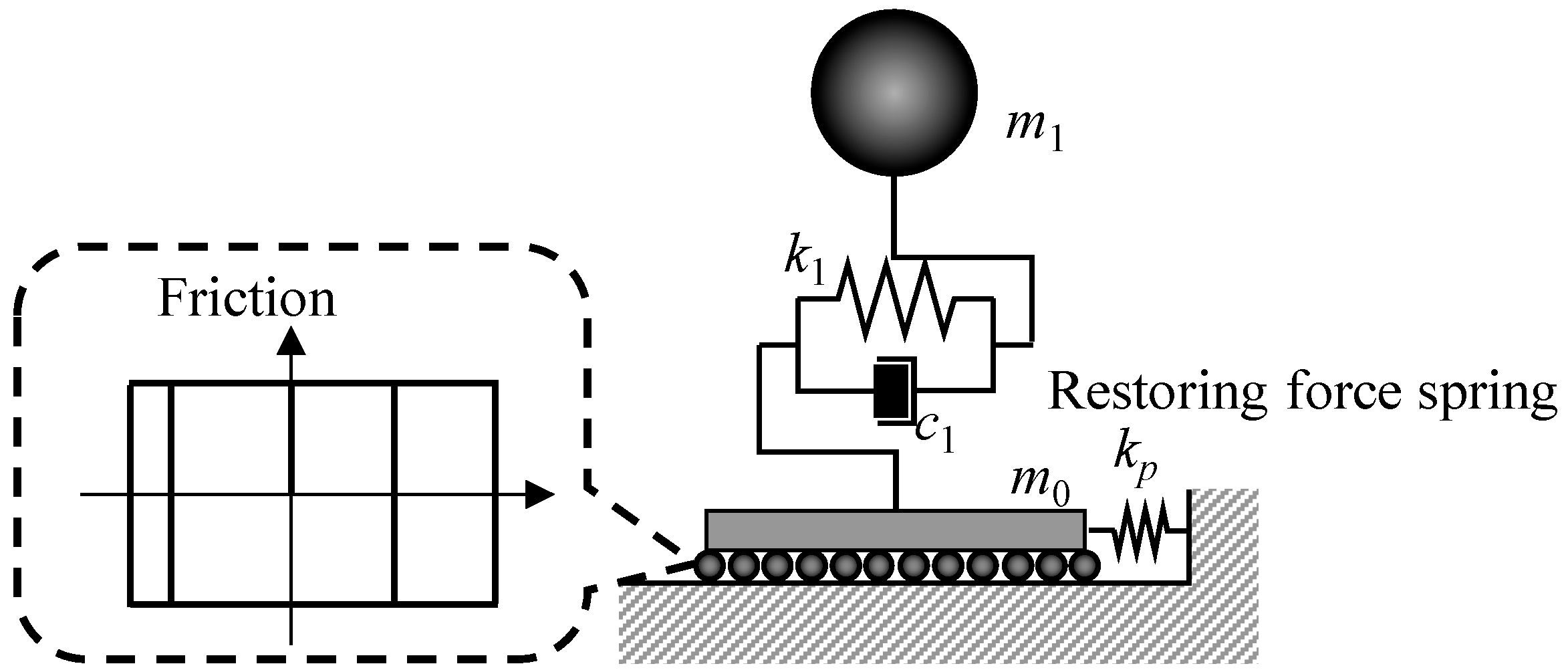
Regarding the residual sliding displacement of a sliding structure, a reasonable design of the restoring force mechanism for the suppression has been proposed based on the concept of pudding [44]. It was developed particularly for a single-story sliding structure along with the seismic estimation, which is referred to as the single-story estimation in this study. The concept of the suppression is a positive use of pounding, which is a common and classical problem for base isolated structures [45,46,47,48,49,50]. For this purpose, the spring is designed to be soft enough so as not to cause a significant increase in the response of the superstructure, having sufficient function for the suppression. Seismic estimation has an important role in evaluating shear forces generated in the superstructure from the sliding and the restoring force mechanism. The effectiveness of the suppression and seismic response estimation has been verified in a shake table experiment on a single-story FSS equipped with rubber bands that were used as the restoring force spring [51]. The configuration of a multi-story FSS equipped with restoring force springs is shown in Figure 1.
This study presents a way to estimate shear coefficients in a multi-story sliding structure with and without the restoring force mechanism, referred to as multi-story estimation in this study. It is basically placed as an advanced and extended study of the single-story estimation. In addition, improvement is introduced as a new form to the estimation so that it can take into account the excitation intensity, which was omitted in the conventional estimation for a single-story sliding structure for the sake of simplification. The multi-story estimation with the improvement on the excitation intensity provides seismic response estimates of sliding structures only from those structural properties without computing dynamic analysis. It greatly benefits the design perspective and understanding of the fundamentals of sliding structures.
This study numerically investigates the effectiveness and accuracy of the multi-story estimation and the new form. The key parameter for the examination is the number of stories in the superstructure in a FSS with or without a restoring force mechanism. Then, this study focusses on a three/six-story FSS with a friction coefficient around 0.2 with and without a restoring force mechanism. These FSS models are simulated through an incremental dynamic analysis (IDA) [52,53,54], which is a common approach for evaluating the seismic performance of base-isolated structures [50,55,56], with the far-field ground motion set listed in [57]. Note that the occurrence of uplift in the FSSs is not considered for either the stick or slip state, because the current development of FSSs mainly focuses on buildings with a low slenderness ratio that are unlikely to cause uplift.
The remainder of this paper is organized as follows. The multi-story estimation for a sliding structure having a multi-story superstructure and a restoring force mechanism is provided together with its new form in Section 2 after the brief introduction of the single-story estimation. The multi-story estimation with the new or conventional form is numerically evaluated through IDA for three/six-story FSS models with and without the restoring force mechanism in Section 3. Finally, the conclusions of this study are presented in Section 4.

2. Suppression of Residual Sliding Displacement and Estimation of Seismic Responses

The multi-story estimation is an extension of a single-story response estimation, which has been developed for the basic sliding structure model having a single-story superstructure, a sliding part and a restoring force mechanism that suppresses its residual sliding displacements without significantly exacerbating the structural responses (Figure 2). The proposed estimation method can evaluate the influence of the restoring force mechanism on the superstructure response.
Firstly, the earlier seismic response estimation method proposed for the single-story superstructure of an FSS with restoring force mechanism design is summarized in Section 2.1. Secondly, the new response estimation method incorporating the seismic intensity measure is introduced in Section 2.2. Then, the multi-story estimation procedure is presented in Section 2.3.

2.1. Response Estimation of a Single-Story Sliding Structure Equipped with a Restoring Force Mechanism

A single-story estimation [44] has been developed based on the basic sliding structure model, which is a two-degree-of-freedom (2DOF) model, together with a restoring force mechanism, as shown in Figure 2. It allows us to consider the influences of both the sliding interface friction coefficient and the restoring force mechanism on the superstructure. For the seismic response estimation procedure, simple analytical models are used for friction and pounding: the friction was represented by the Coulomb’s friction model, and the pounding was expressed by the Kelvin model [58], which is the simplest linear form even though actual pounding has some nonlinear effects [59,60]. These simple models are practically useful for the preliminary design of the restoring force mechanism and for understanding the global seismic response of the FSS.
The original study with numerical verifications using various ground motions found that a gap between the sliding structure and the restoring force mechanism did not affect the response of the superstructure considerably and the case without the gap resulted in the least residual sliding displacement. Therefore, this study does not consider the gap.
When a sliding structure is represented by the model in Figure 2, the estimation provides a shear coefficient of the superstructure by the following form:
C ¯ P = C ¯ 2 + C ¯ p * 2 = μ s 2 1 + γ + α 1 + β 2 + 4 λ 2 μ e 2
where { C ¯ , C ¯ p * } is the set of shear coefficients applied to the superstructure derived from the friction and restoring force spring, respectively; α (= m0/m1) is the mass ratio; β ( [ 1 , 1 ] ) is the contribution factor of the ground motion acceleration at the onset of sliding; γ ( [ 0 , 2 ] ) is the contribution factor of the superstructure’s initial deformation at the onset of sliding; μs is the maximum static friction coefficient; μe is the equivalent friction coefficient associated with the restoring force mechanism; and λ is the amplitude ratio between an anticipated ground motion intensity and actual one. Note that Equation (1) can represent the case even without the spring by setting μe = 0.
In Equation (1), C ¯ p * is linked with the equivalent friction coefficient μe, and it was found to be associated with the restoring force stiffness [44], as follows:
k p = M π g 2 v p μ e 2 ,
where M (= m0 + m1) is the total mass of the sliding structure; g (= 9.8 m/s2) is the gravitational acceleration; and vp is the maximum sliding velocity during the contact with the restoring force spring and structure. Based on Equation (2), the spring stiffness kp can be designed by assuming the equivalent friction coefficient μe, which corresponds to the allowable shear force additionally induced in the sliding part by the restoring force spring. In addition, according to the earlier study [44], vp can be almost replaced by the peak ground velocity (PGV) of a ground motion especially when μe is reasonably small to μs (e.g., μe = μs/2). When the PGV of an actual ground motion applied to the structure is v p * , the gap can be reflected in Equation (1) as λ = v p * / v p .
Equation (1) can be further simplified, based on the median values of β and γ (i.e., β = 0.0 and γ = 1.0), as follows:
C ¯ P = C ¯ 2 + C ¯ p * 2 = μ s 2 2 + α 2 + 4 λ 2 μ e 2 ,
which is referred to as the conventional form in this study. Its effectiveness has been verified in numerical simulations [44] and experiments [51] on the single-story sliding structure based on the friction coefficient around 0.2, for both cases with and without a restoring force mechanism.
Equation (3) is highly practical as it allows for estimating the response of the sliding structure without a restoring force mechanism (i.e., μe = 0.0) only from μs and α, which are basic structural parameters. As μe can be decided in relation with μs (e.g., μe = μs/2), Equation (3) depends on λ and provides the corresponding estimates.

2.2. New Forms of β and γ

In the conventional estimation form, C ¯ becomes constant when μe = 0, corresponding to the case without the restoring force spring, because of using the median values: β = 0.0 and γ = 1.0. Its reasonable agreement with the seismic responses of a sliding structure is attributed to its isolation effect, which makes the responses insensitive to the ground motion intensities. However, the responses are not completely independent from the intensities, and its influence needs to be reflected in the estimation to be more precise especially at high intensity range.
A new form is introduced by improving β and γ so that they can vary according to the excitation intensity, as follows:
γ I = 2 I I + I s = 2 I / I s I / I s + 1 β I = I I s I + I s = I / I s 1 I / I s + 1 ,
where I (≥0) is the ground motion intensity; and Is (≥0) is the standard intensity that produces the median values: γ I s = 1 and β I s = 0 . Note that I/Is is the dimensionless ratio of the intensity normalized by the standard intensity. This study employs PGV as the excitation intensity because it is used in the seismic response estimation in Equations (1) and (3), as well as in the design of the restoring force spring in Equation (2). Even when it is changed to peak ground acceleration (PGA) or response spectra, β and γ remain the same due to their linear relations with PGV and its reliance on the ratio of the intensity.
Equation (4) is the new form proposed in this study, in contrast with the conventional form (i.e., β = 0.0 and γ = 1.0), which does not take into the account of the excitation intensity. The examination of the new form is an important subject of this study, and it is compared with the conventional form in numerical simulations on multi-story sliding structures in Section 3.

2.3. Response Estimation of a Multi-Story Sliding Structure Equipped with a Restoring Force Mechanism

The multi-story estimation, which is a seismic response estimation of a multi-story sliding structure shown in Figure 3a, is developed by extending the estimation of a single-story sliding structure, as shown in Figure 3b. This extension is made by the following two steps:
  • The multi-story superstructure is converted into a single story, as shown in Figure 3b, and C ¯ P is calculated from the converted structure.
  • C ¯ P is distributed to each story of the superstructure, based on distribution factors.
By embodying these steps with some distribution factors, the shear coefficient estimation of the ith story in the multi-story superstructure, which is the key of this study, is described by
C ¯ P i = C ¯ i 2 + C ¯ p i * 2 = C ¯ D ¯ i 2 + C ¯ p * D ¯ p i 2 ,
where { C ¯ i , C ¯ p i * } is the set of the ith story’s shear coefficients induced by the friction and the restoring force spring, respectively; and { D ¯ i , D ¯ p i } is the set of the ith story’s distribution factors associated with C ¯ and C ¯ p * , respectively. Based on C ¯ P i , the inter-story drift on the ith story is also estimated by
δ ¯ i = C ¯ P i / k i .
As shown above, the determination of distribution factors in Equation (5) is fundamental for the estimation. Thus, a set of the distribution factors of D ¯ and D ¯ p is introduced below.

2.3.1. Distribution Factor D ¯ i

D ¯ i is the distribution factor applied to C ¯ , which is the estimated shear coefficient to be induced by sliding alone. It is more influenced by the stick state rather than the sliding state, as the shear coefficient of the superstructure peaks immediately after the onset of sliding. This indicates that the distribution factor of the superstructure in multi-story sliding structures can be similar to that of fixed-base structures, which is associated with linear and hyperbolic mass distributions such as the Ai distribution in the Japanese design code [61,62]. However, it should be noted that the sliding structure has the isolation effect, which the base-fixed structure does not have, resulting in the less amplification of the superstructure’s responses.
When a sliding structure has an N-story superstructure, the estimate C ¯ corresponds to the shear coefficient in the mid-part of the superstructure at the N/2-story: C ¯ P N / 2 = C ¯ P . Its higher parts should have larger shear coefficients due to the amplification, while the lower parts should have smaller shear coefficients.
Based on the above considerations, this study introduces the following equation as the distribution factor D ¯ i applied to C ¯ i :
D ¯ i = ψ i 3 4 .
where ψ i = α i α mid ; α i = j = i N m j / j = 1 N m j ; and α mid is the mid part’s mass ratio of the structure. Equation (7) is the product of the geometric mean of ψ i 1 and ψ i 1 2 , which, respectively, are related to the linear and hyperbolic mass distributions centralized by α mid . Note that α mid varies depending on the total number of stories and the mass distribution as follows:
α mid = α N c + 1 H c + α N c 1 H c .
where H c = 1 2 i = 1 N m i i = 1 N c m i m N c + 1 , 0 H c 1 ; and Nc is the nearest but lower story to the center of mass, counted from the 1st story.

2.3.2. Distribution Factor D ¯ p i

D ¯ p i is the distribution factor applied to C ¯ p * , which is the estimated shear coefficient of the superstructure to be induced only by the restoring force spring. As this spring is functional mainly at sliding for generating pulse-like resisting force, it is influenced by the sliding state rather than the stick state. Thus, it should have a different shape from D ¯ i . In this respect, the restoring force mechanism added to a sliding structure should have a greater influence on the stories closer to the attachment point, indicating that the influence of the restoring force mechanism is less on the higher stories.
Based on the above consideration, this study introduces the following equation as the distribution factor D ¯ p i applied to C ¯ p * :
D ¯ p i = j = i N m j k = 1 N j = 1 k m j .
Note that D ¯ p i holds the condition of i = 1 N D ¯ p i 2 = 1 .

2.3.3. Examples of D ¯ i and D ¯ p i

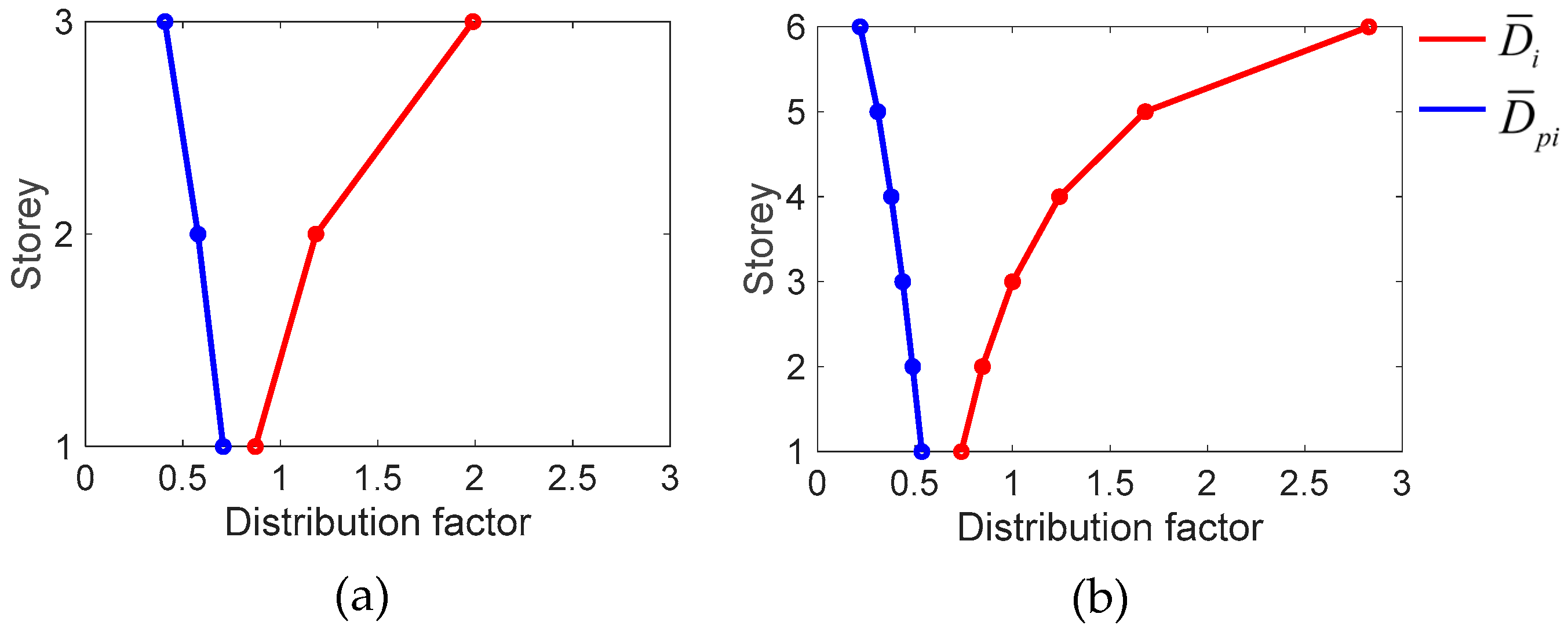
The distribution factors of D ¯ i and D ¯ p i are illustrated in Figure 4 for sliding structures with three-story and six-story superstructures having the same mass on each story. As shown in Figure 4, D ¯ p i has a decreasing relationship with the number of stories, while D ¯ i has an increasing relationship with the number of stories. Figure 4 shows that the mid-parts of these three-story and six-story structures correspond to Nc = 1.5 and 3.0, respectively, as D ¯ i at these points become 1.0.
The effectiveness of these distribution factors for the seismic response estimation of multi-story sliding structures is discussed in numerical simulations in the following section.

3. Numerical Simulations to Examine the Multi-Story Estimation

To examine the proposed multi-story estimation and the new form, numerical simulations were performed to three/six-story sliding elastic structures with and without a restoring force mechanism. These numbers of stories are major targets for the FSS. The examination was performed with the IDA using a ground motion set and procedures in FEMA P695 [57].
After the brief introduction of IDA in Section 3.1, the estimations for the three-story and six-story sliding structures are examined in detail in Section 3.2 and Section 3.3, respectively.

3.1. Incremental Dynamic Analysis and Indices for the Estimation Accuracy

The IDAs were performed with the far-field ground motion set in FEMA P695 [57], and the details of the 44 ground motions are listed in Table 1. The median of those PGVs is 0.41 m/s. The ground motions were uniformly rescaled to make the median become 0.5 m/s, and those acceleration response spectra are illustrated in Figure 5. The amplitude was used as the standard ratio of the 44 ground motions: R44 = 1.0. The IDAs were performed by gradually increasing it in the range of 0.0–3.0 with the increment of 0.1, to see the response of the sliding structures under different ground motion intensities. The ratios of R44 = 0.5 and 1.0 almost correspond to Lv1 and Lv2 ground motion intensities considered in the Japanese design, respectively. The Lv2 intensity is considered as the design basis earthquake, and its 1.5 times intensity, referred to as Lv3, corresponds to the maximum considered earthquake.
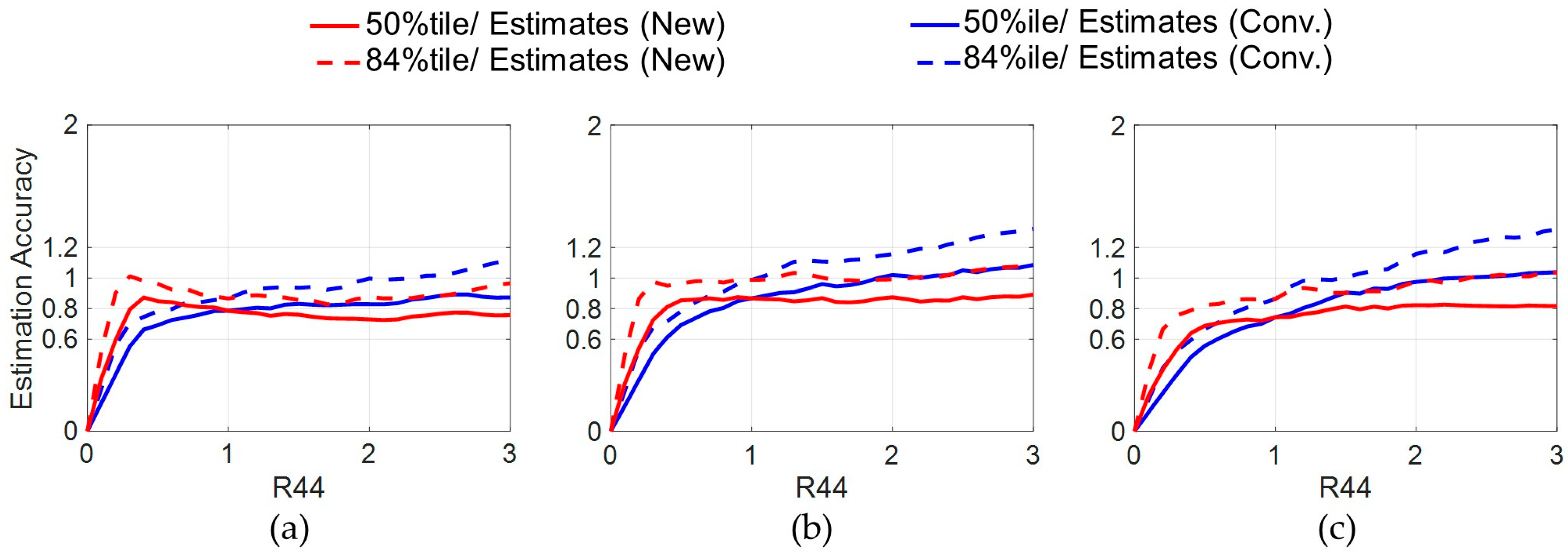
This study focusses on the maximum and residual values of sliding displacement and each story’s the shear coefficient and inter-story drift within the superstructure as major structural responses in the sliding structures. The estimation accuracy is evaluated by the median and 84-percentile values of the IDA results. This study evaluates an estimation as good [fair] when either of the curves falls within the ±20% [−40% to +20%] estimation error range. These ranges have been decided by assuming that the randomness of ground motions and the nonlinearity of the sliding structure will each cause at least a 10% error. Then, a good estimation needs to be within a ±20% error range. The moderate estimation was decided by making only the overestimation tolerance twice, to be tolerant of an overestimation but not of an underestimation.

3.2. Three-Story FSS Model

The multi-story estimation with the new form is firstly examined through a series of IDAs with a three-story sliding elastic structure with and without a restoring force mechanism.

3.2.1. Numerical Model of a Three-Story FSS

The details of the three-story FSS model and restoring force parameters are listed in Table 2. The total mass of the structure was fixed as M = 600 × 103 kg, which was homogeneously allocated to each story including the sliding part. The superstructure was designed to make its first natural frequency at the stick state become f1 = 2.0 Hz. This natural frequency was decided by referencing typical low-rise steel buildings in Japan and experiments on full-scale steel buildings conducted at E-Defense [63,64,65,66]. Then, based on the Ai distribution in the Japanese design [61,62], a set of stiffness in the superstructure was determined to be those in Table 2. The damping coefficients were determined by the stiffness proportional damping with the first frequency and the damping ratio of 2.0%.
As the kinematic friction coefficient is commonly known to be affected by the sliding velocity [67,68], this study is based on the following friction model:
μ v = μ min + μ max μ min e ρ v ,
where {μmax, μmin} is the set of maximum and minimum friction coefficients, respectively; ρ is the intensity of the velocity dependence; and v is the sliding velocity. This study set these parameters to μmax = μs = 0.21, μmin = 0.16 and ρ = 20 s/m, based on the experimental results of the graphite-lubricated mortar and steel [24,25]. The stable friction of the interface has been obtained in different experimental setups with various excitations [26,27,28], demonstrating its low variation. The simulations in this study were based on an elastic–perfectly plastic model to demonstrate the states of stick and slip seamlessly. The stiffness at the stick state was determined by k0 = μsMg/Δ0 with the elastic limit: Δ0 = 0.001 mm, and the stiffness at the sliding state varied to demonstrate Equation (10).
The stiffness of a restoring force spring in Table 2 was designed using Equation (2) with the total mass M, μe = 0.1 and vp = 0.5 m/s. This design allows the spring to generate the equivalent friction coefficient in the sliding interface by 0.1 and 0.2 to the ground motions of vp = 0.5 and 1.0 m/s, respectively.

3.2.2. Three-Story FSS Model Without a Restoring Force Spring

The IDA results for the three-story FSS model without the restoring force spring and estimation accuracy are summarized in Table 3 and illustrated in Figure 6, Figure 7, Figure 8 and Figure 9. The estimates were calculated by the multi-story estimation using Equations (1) and (5) with the distribution factors of Equations (7) and (9), together with two different calculations on C ¯ . The conventional form is based on β = 0.0 and γ = 1.0, while the new form is based on Equation (4) with Is = 0.5 m/s, which corresponds to the Lv2 ground motion intensity in Japan.
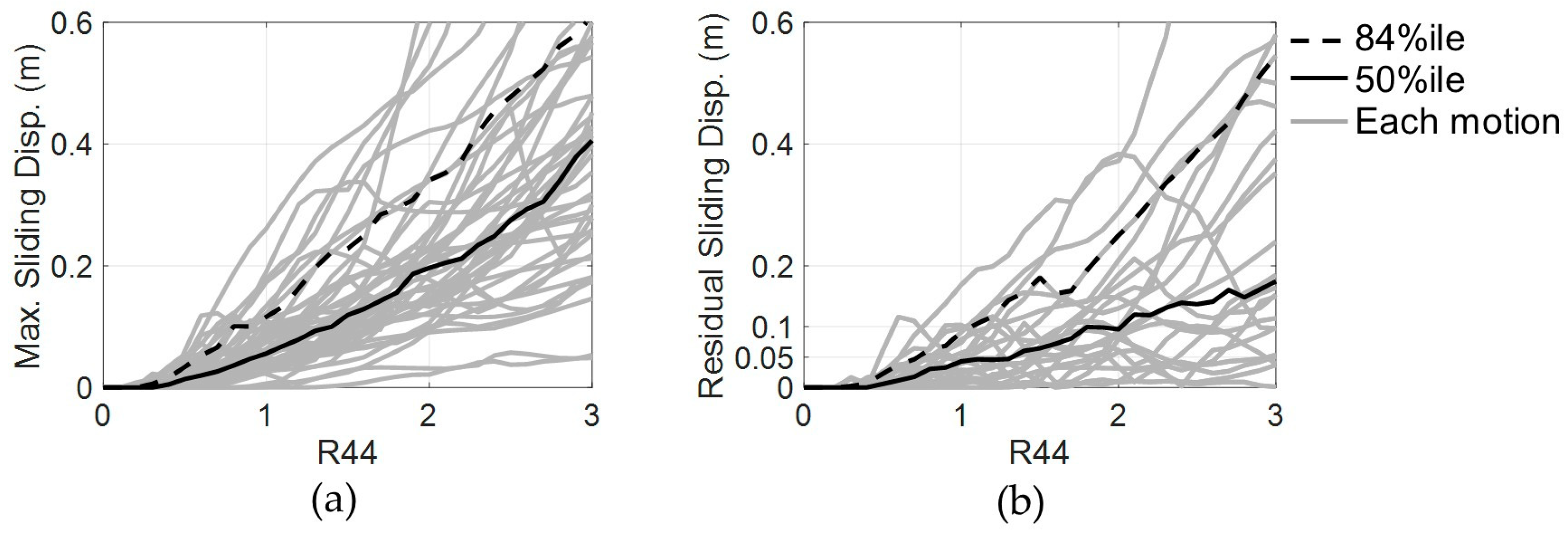
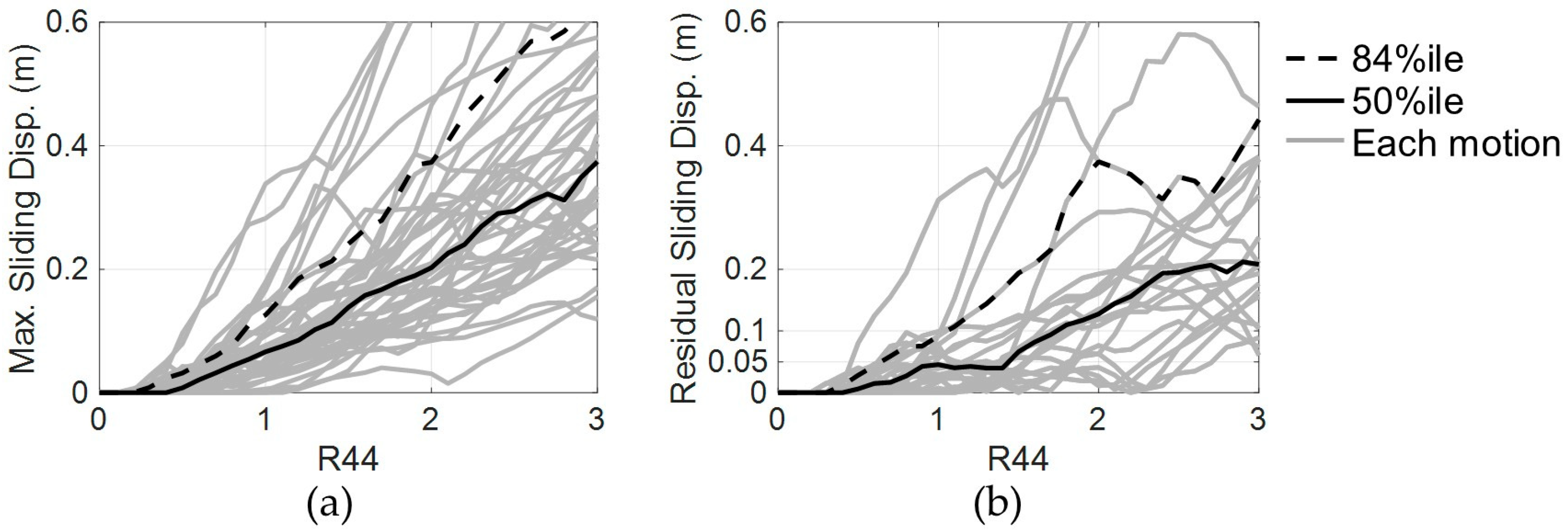
Figure 6a shows that the FSS model starts to slide by the ground motion intensity around R44 = 0.5, corresponding to PGV = 0.25 m/s. Below the ground motion intensity, it does not slide, behaving as a conventional structure. Figure 6b clarifies that the FSS model without the restoring force mechanism has large residual sliding displacement especially after subjecting to high intensity excitations: the median values of the residual sliding displacement have become over 0.1 m at the intensities over R44 = 2.0, and the 84-percentile values have reached to such large residue even at much smaller intensities around R44 = 1.0. In this case, the maximum sliding displacement and its residue tend to become larger as increase in the ground motion intensity, as shown in Figure 6a,b. In contrast, the responses of the superstructure become insensitive to the excitation intensities due to the nonlinear effect of the sliding, which is shown in Figure 7.
The estimates, produced by the multi-story estimation with the new form, reasonably agreed with the responses, as shown in Figure 7. According to Figure 8, its accuracy is good, as the 84th-percentile curves for all the stories fall in the ±20% error in the major amplitude range R44 = 0.5–3.0. The accuracy of the new form is higher than the conventional form, because of the less fluctuation in the accuracy, as shown in Figure 8. According to Table 3, the conventional form tends to underestimate the responses of higher stories at over PGV = 1.0 m/s (R44 = 2.0), while the new form reasonably matches the IDA median results. Figure 9 illustrates that the multi-story estimation with the new form can be extensively used to estimate the inter-story drift of the superstructure, as the accuracy of all stories is sufficiently high in the wide range of intensities.

3.2.3. Three-Story FSS Model with a Restoring Force Mechanism

IDA results for the three-story FSS model with the restoring force mechanism in Table 2 are summarized in Table 4 and illustrated in Figure 10, Figure 11, Figure 12 and Figure 13. Note that the estimates were calculated by the same way in Section 3.2.2.
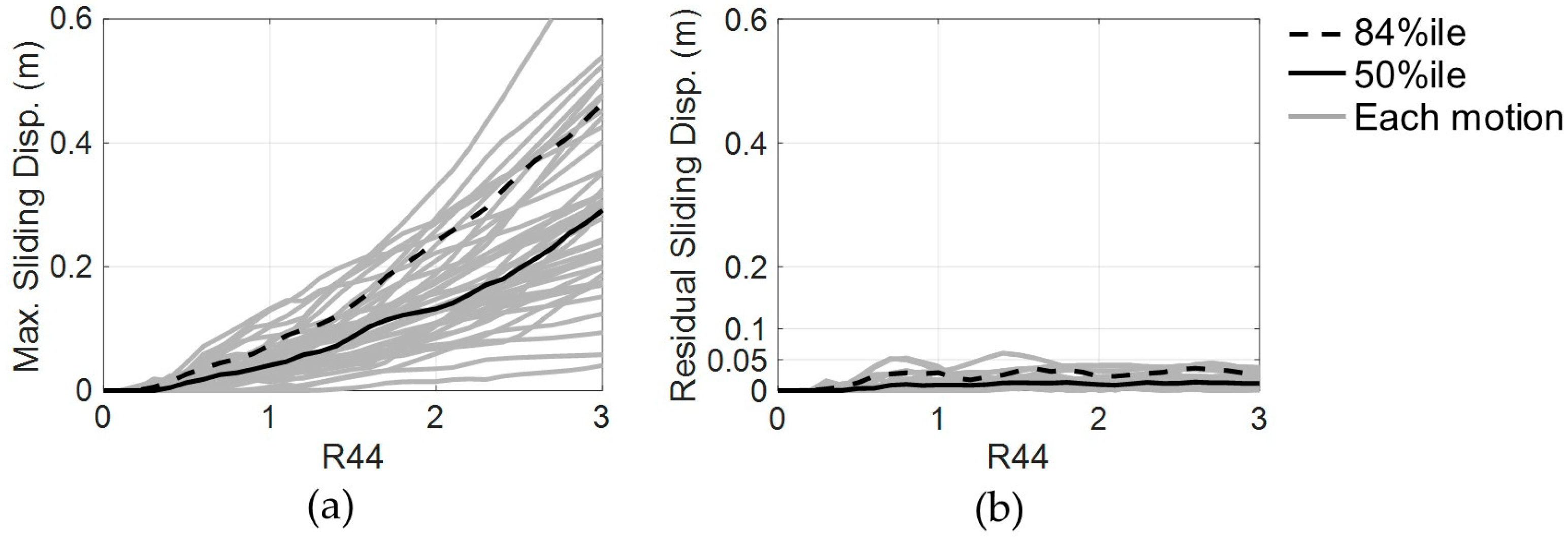
The restoring force mechanism does not affect the onset of sliding, and the FSS model equipped with the spring also starts to slide by the ground motion intensity around R44 = 0.5, corresponding to PGV = 0.25 m/s, as observed in Figure 10a. According to the comparison with Figure 6b and Figure 10b, the restoring force mechanism is greatly effective in suppressing the residual sliding displacement, keeping it below 0.05 m at all considered intensities. Although the restoring force mechanism is introduced to mainly suppress the residual sliding displacement, it secondarily has a function to reduce the maximum sliding displacement to some degree, as seen from the comparison with Figure 6a and Figure 10a.
Comparing Figure 7 and Figure 11, the shear coefficients in the FSS model without and with the restoring force mechanism do not differ greatly, indicating that the intended performance has been achieved by the design of the restoring force mechanism. However, the influence of the restoring force mechanism can be seen slightly in the first story, as small increases in the shear coefficient, particularly at high intensities above R44 = 1.5 in Figure 11a.
The estimates, produced by the multi-story estimation with the new form, show good correspondence with the structural responses, especially with the 84th-percentile curves in Figure 11, resulting in the high estimation accuracy seen in Figure 12. Its accuracy is good in the overall considered intensity range with less fluctuation in comparison with the conventional form, which shows the underestimation tendency at the high intensities around PGV = 1.5 m/s (R44 = 3.0) in Table 4. In addition, the estimates of the inter-story drift again have reasonably agreed with the IDA results, as shown in Figure 13.

3.3. Six-Story FSS Model

To further investigate the accuracy of the multi-story estimation and the new form, a series of IDAs was performed with a six-story FSS model with and without a restoring force mechanism.

3.3.1. Numerical Model of a Six-Story FSS

The parameters of the six-story FSS model and the restoring force mechanism are listed in Table 5. The total mass M was unchanged from the examination in Section 3.2, and it was again homogeneously distributed to each story. Steel structures in Japan tend to have the first natural periods in 0.6–0.7 sec which are simply calculated by 0.03·H where H is the building height. Thus, the set of stiffness in the superstructure was designed to have the first natural frequency f1 = 1.5 Hz at the stick state, based on the same manner in Section 3.2. The set of damping in the superstructure was determined by the stiffness proportional damping with the first frequency and the damping ratio of 2.0%. Apart from the mass m0, the sliding part in the six-story FSS model had identical parameters with those of the three-story FSS model.

3.3.2. Six-Story FSS Model Without a Restoring Force Mechanism

The IDA results for the six-story FSS model without the restoring force mechanism and estimation accuracy are summarized in Table 6 and illustrated in Figure 14, Figure 15, Figure 16 and Figure 17. The estimates were calculated in the same way as in Section 3.2, i.e., the multi-story estimation based on Equations (1), (5), (7) and (9), with two different calculations on C ¯ by the conventional form (β = 0.0 and γ = 1.0) and the new form (Equation (4) with Is = 0.5 m/s).
Figure 14a shows that this FSS model also starts to slide by the ground motion intensity around R44 = 0.5 and does not slide below the intensity. According to the comparison with Figure 6a and Figure 14a, the results of the sliding displacement in this six-story FSS model are quite similar with those in the three-story FSS model. This indicates that the difference in the superstructures does not greatly affect the sliding, suggesting that the friction and the excitations almost govern the sliding.
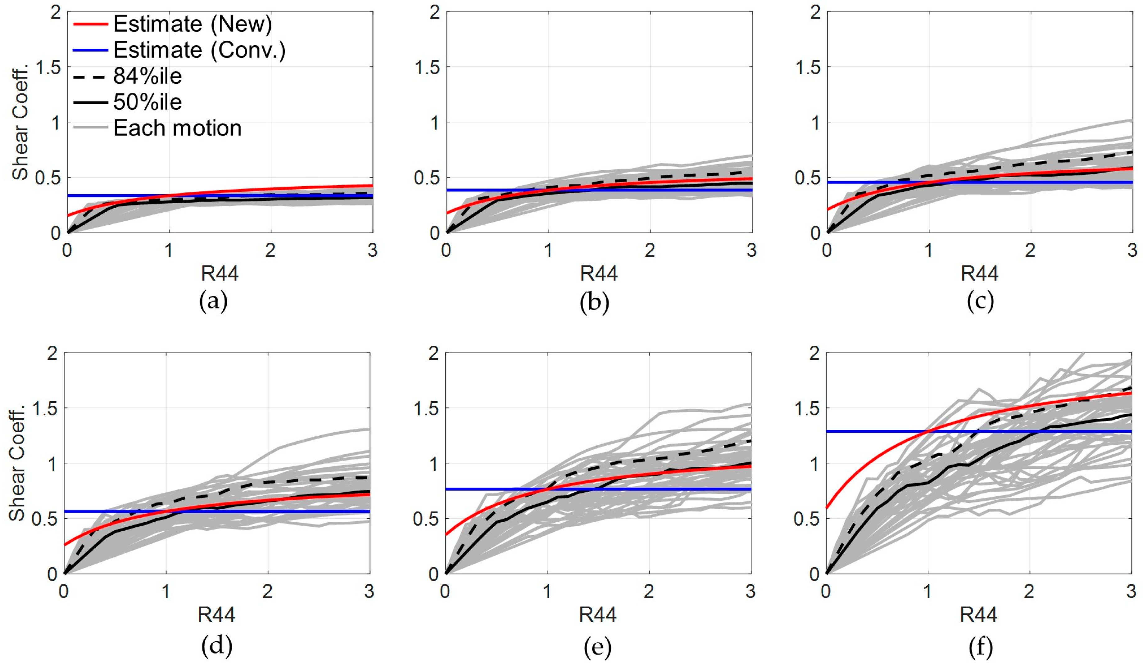
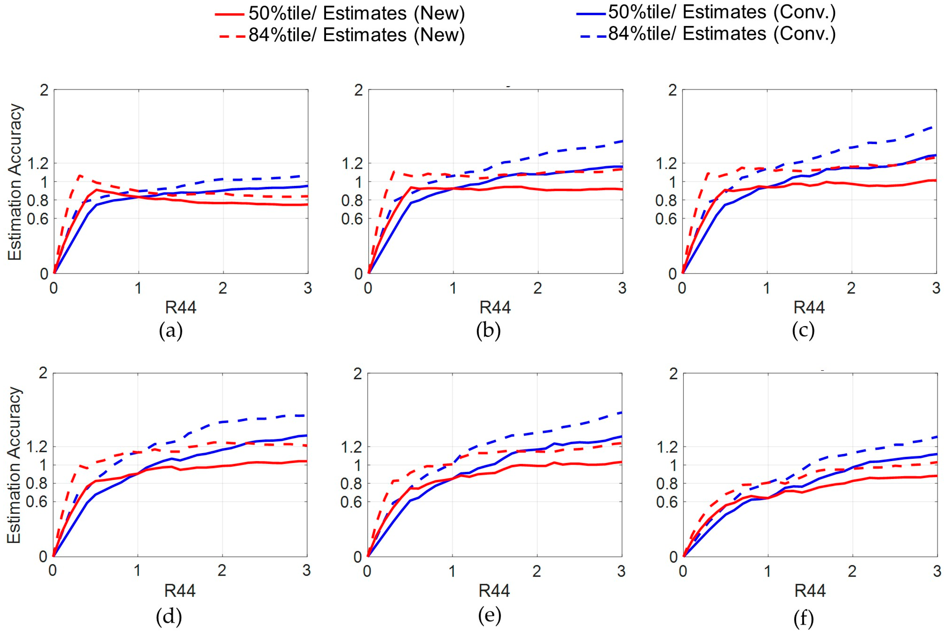
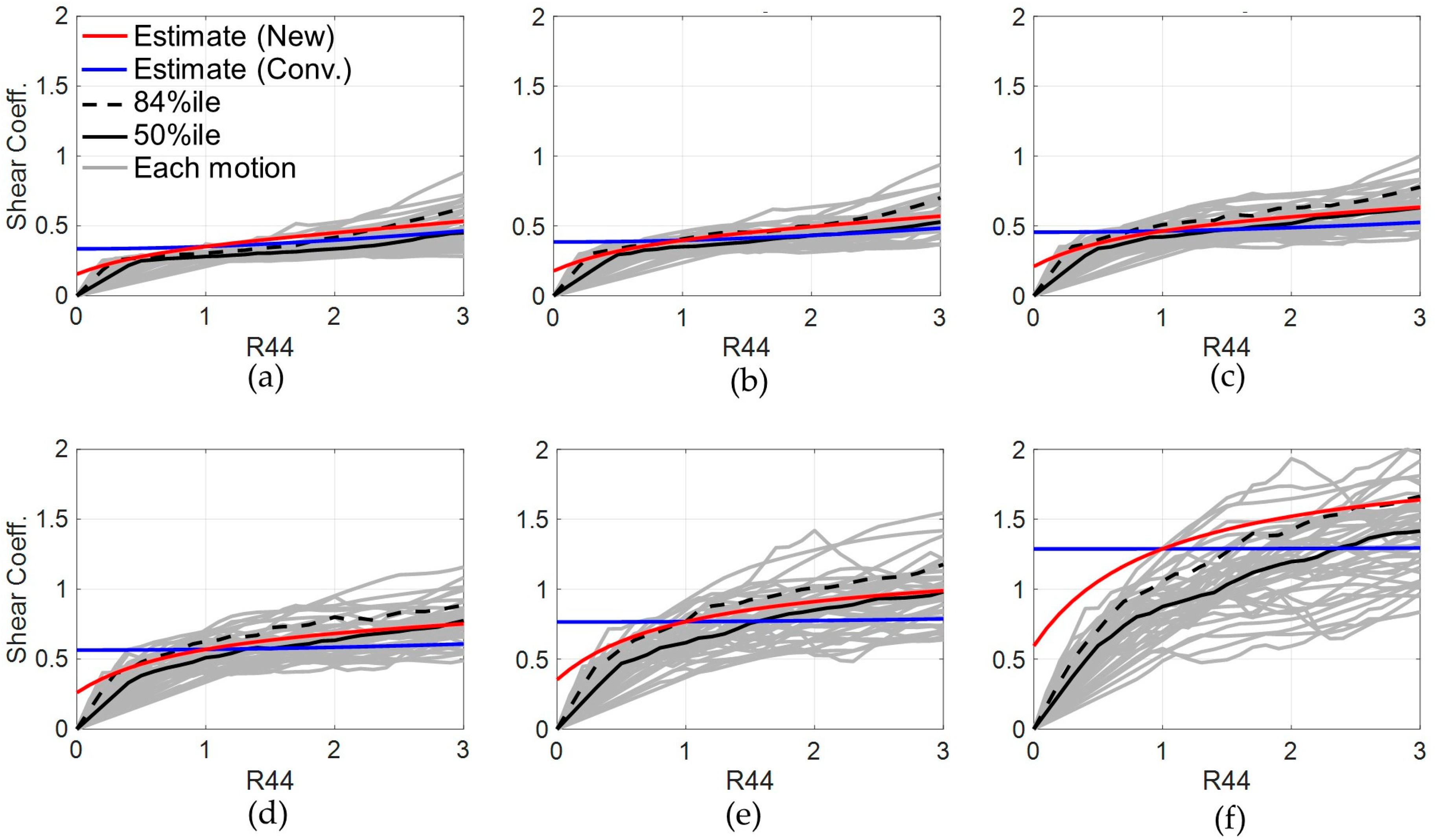
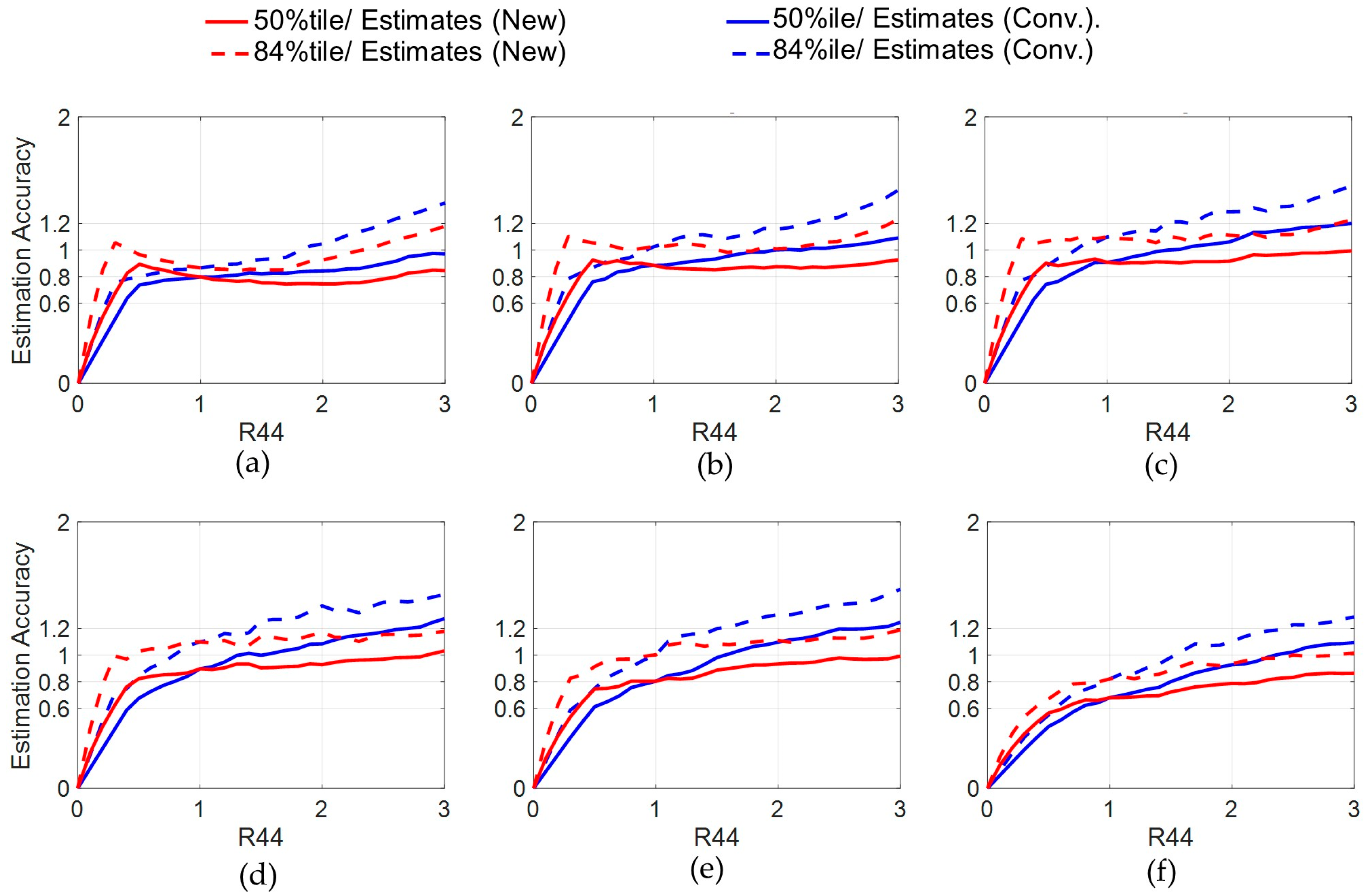
The estimates, generated by the multi-story estimation with the new form, show good agreement with the IDA curves over the wide range of excitation intensities. Contrarily, the estimate by the conventional form does not agree such well, mainly because it produces a single estimate for all intensities, as can be seen in Figure 15 and Table 6. The accuracy of the multi-story estimation with the new form is good as the 84-percentile curves for almost all stories fall in ±20% error range as shown in Figure 16. In contrast, the estimates based on the conventional form are found to underestimate the responses especially at high intensities over R44 = 2.0, as seen in Table 6, clarifying the superiority of the new form. The estimates of the inter-story drift on each story are sufficiently close to the IDA results, as shown in Figure 17.
The above results justify that the multi-story estimation is reliable to the six-story FSS model without a restoring force mechanism as well and the new form outperforms the conventional form.

3.3.3. Six-Story FSS Model with a Restoring Force Mechanism

The IDA results for the six-story FSS model with the restoring force mechanism and estimation accuracy are summarized in Table 7 and illustrated in Figure 18, Figure 19, Figure 20 and Figure 21. Note that the estimates were calculated in the same way in other examinations.
The restoring force mechanism successfully retains the residual sliding displacement within 0.05 m, as shown in Figure 18b, and the effectiveness is clarified in comparison with Figure 14b. In addition, the restoring force mechanism contributed to reducing the maximum sliding displacement to some degree, approximately by 30%, according to Figure 14a and Figure 18a.
Regarding the shear coefficients in the superstructure in Figure 19, the estimates by the multi-story estimation with the new form well agree with the IDA curves, keeping the good agreements even at high excitation intensities. Its accuracy is evaluated to be good, because the 84th-percentile curves on all stories fall in ±20% error range in the major intensities range: R44 = 0.5–3.0 as shown in Figure 20. The accuracy is less fluctuated than that based on the conventional form, which shows some unpreferable underestimations of the median curves at the high intensities in Figure 20 and Table 7. Figure 21 illustrates that the inter-story drift of the six-story FSS model with the spring also can be accurately assessed by the multi-story estimation with the new form.

4. Conclusions

This study newly introduced a multi-story estimation that allows us to estimate the shear coefficients of a multi-story FSS model with a restoring force mechanism. This estimation was developed by extending the single-story estimation that was developed specifically for a single-story FSS model with the restoring force mechanism. In the multi-story estimation, a shear coefficient of the superstructure is estimated by regarding it as a single-story, and the obtained coefficient is distributed to each story based on distribution factors associated with its mass ratio. Then, this study introduced two distribution factors related to shear coefficients derived from sliding and the restoring force mechanism. As the original single-story estimation was developed to provide a constant estimate even to different ground motion intensities for simplicity, it tends to have a slight gap with the actual responses especially at high excitation intensities. To this aspect, this study introduced a new form as an improvement that takes into the account of the influence of the intensity.
The multi-story estimation and the new form were examined for key parameters such as the number of stories in the superstructure in a FSS with or without a restoring force mechanism, using various ground motions. Then, IDAs were performed for a three/six-story FSS model, which is based on the friction coefficient of about 0.2, with and without a restoring force mechanism. The major findings of the numerical examinations are summarized as follows:
The multi-story estimation was found to be sufficiently reliable and useful to estimate those seismic responses, as those estimates agreed well with the IDA results of these three/six-story FSS model, with high accuracies not exceeding the error range of ±20%. The new form was also found to be effective, as the estimates based on the form more reasonably matched with curvatures of the IDA results than the estimates of conventional one.
The IDAs in this study supported that multi-story FSS models based on the friction coefficient around 0.2 are greatly effective in mitigating the seismic responses of the shear coefficient and inter-story drift. A reasonably designed restoring force mechanism is also effective in suppressing the residual sliding displacement without significantly accelerating the responses in the multi-story FSS model.
The obtained results highlighted the high utility of the proposed estimation enabling us to estimate responses of FSSs with reasonable accuracy by using simple formulations instead of computing dynamic analysis of the structures. It is greatly beneficial to the design in practice and physical understanding of the sliding structures.
As the multi-story FSS models investigated in this study model were based on the design using the shear force distribution in Japan, its use now is mainly limited to FSSs based on the design or similar ones. The feasibility of the multi-story estimation needs to be further examined with different types of structural models including the cases of irregular mass or stiffness distributions. In addition, its accuracy needs to be examined in experiments on a multi-story sliding structure with and without a restoring force mechanism.
The current development of FSSs is mainly aimed at buildings with a low slenderness ratio that are unlikely to uplift and impair the sliding interface. However, the proposed multi-story estimation could be useful for evaluating uplift in FSSs, and this application is a topic for further study. To realize the FSS in practice, the long-term stability and durability of the graphite-lubricated sliding interface with steel and mortar also needs to be examined in further experimental studies.

Author Contributions

Conceptualization, R.E. and C.Y.; methodology, R.E.; software, R.E.; validation, R.E.; formal analysis, R.E.; data curation, R.E.; writing—original draft preparation, R.E. and C.Y.; writing—review and editing, R.E. and C.Y.; visualization, R.E.; project administration, R.E.; funding acquisition, R.E. All authors have read and agreed to the published version of the manuscript.

Funding

This study was supported by the research grant (No.: 24H00344) from Japan Society for the Promotion of Science.

Data Availability Statement

The data presented in this study are available in the article. Further inquiries can be directed to the corresponding author.

Conflicts of Interest

The authors declare no conflicts of interest.

Abbreviations

The following abbreviations are used in this manuscript:
IDAIncremental dynamic analysis
FEMAFederal Emergency Management Agency
FSSFree-standing structure
PGVPeak ground velocity
PGAPeak ground acceleration
DOFDegree-of-freedom

References

  1. Kelly, J.M. Aseismic base isolation: Review and bibliography. Soil Dyn. Earthq. Eng. 1986, 5, 202–216. [Google Scholar] [CrossRef]
  2. Yenidogan, C. Earthquake-Resilient Design of Seismically Isolated Buildings: A Review of Technology. Vibration 2021, 4, 602–647. [Google Scholar] [CrossRef]
  3. Yenidogan, C.; Erdik, M. A comparative evaluation of design provisions for seismically isolated buildings. Soil Dyn. Earthq. Eng. 2016, 90, 265–286. [Google Scholar] [CrossRef]
  4. Yenidogan, C. Evaluation of Overall Seismic Performance of RC Structures and Effectiveness of Seismic Isolation Technology Under Extreme Events: February 6, 2023, Earthquakes. Buildings 2025, 15, 990. [Google Scholar] [CrossRef]
  5. Zayas, V.A.; Low, S.S.; Mahin, S.A. The FPS Earthquake Resisting System Experimental Report, Report No. UCB/EERC-87/01; Earthquake Engineering Research Center, University of California: Berkeley, CA, USA, 1987. [Google Scholar]
  6. Mokha, A.; Constantinou, M.C.; Reinhorn, A.M.; Zayas, V.A. Experimental Study of Friction-Pendulum Isolation System. J. Struct. Eng. 1991, 117, 1201–1217. [Google Scholar] [CrossRef]
  7. Fenz, D.M.; Constantinou, M.C. Behaviour of the double concave Friction Pendulum bearing. Earthq. Eng. Struct. Dyn. 2006, 35, 1403–1424. [Google Scholar] [CrossRef]
  8. Becker, T.C.; Mahin, S.A. Experimental and analytical study of the bi-directional behavior of the triple friction pendulum isolator. Earthq. Eng. Struct. Dyn. 2012, 41, 355–373. [Google Scholar] [CrossRef]
  9. Turer, A.; Özden, B. Seismic base isolation using low-cost Scrap Tire Pads (STP). Mater. Struct. 2008, 41, 891–908. [Google Scholar] [CrossRef]
  10. Spizzuoco, M.; Calabrese, A.; Serino, G. Innovative low-cost recycled rubber–fiber reinforced isolator: Experimental tests and Finite Element Analyses. Eng. Struct. 2014, 76, 99–111. [Google Scholar] [CrossRef]
  11. Calabrese, A.; Spizzuoco, M.; Serino, G.; Della Corte, G.; Maddaloni, G. Shaking table investigation of a novel, low-cost, base isolation technology using recycled rubber. Struct. Control. Heal. Monit. 2015, 22, 107–122. [Google Scholar] [CrossRef]
  12. Tsiavos, A.; Alexander, N.A.; Diambra, A.; Ibraim, E.; Vardanega, P.J.; Gonzalez-Buelga, A.; Sextos, A. A sand-rubber deformable granular layer as a low-cost seismic isolation strategy in developing countries: Experimental investigation. Soil Dyn. Earthq. Eng. 2019, 125, 105731. [Google Scholar] [CrossRef]
  13. Tsiavos, A.; Sextos, A.; Stavridis, A.; Dietz, M.; Dihoru, L.; Alexander, N.A. Experimental investigation of a highly efficient, low-cost PVC-Rollers Sandwich (PVC-RS) seismic isolation. Structures 2021, 33, 1590–1602. [Google Scholar] [CrossRef]
  14. Takagi, J.; Masui, T.; Araki, Y.; Ikago, K.; Pareek, S.; Lee, S.; Suzuki, Y.; Enokida, R.; Guo, J.; Shrestha, K.C.; et al. Development of low-cost rolling base isolation system for seismic protection of rubble stone masonry buildings in Himalayan Mountain range. Front. Built Environ. 2024, 10, 1495051. [Google Scholar] [CrossRef]
  15. Cilsalar, H.; Constantinou, M.C. Behavior of a spherical deformable rolling seismic isolator for lightweight residential construction. Bull. Earthq. Eng. 2019, 17, 4321–4345. [Google Scholar] [CrossRef]
  16. Nanda, R.P.; Shrikhande, M.; Agarwal, P. Low-Cost Base-Isolation System for Seismic Protection of Rural Buildings. Pract. Period. Struct. Des. Constr. 2016, 21, 04015001. [Google Scholar] [CrossRef]
  17. Campbell, W.E. Studies in boundary lubrication. Tran. ASME 1939, 61, 633–641. [Google Scholar]
  18. Tassios, T.P.; Vintzēleou, E.N. Concrete-to-Concrete Friction. J. Struct. Eng. 1987, 113, 832–849. [Google Scholar] [CrossRef]
  19. Rabbat, B.G.; Russell, H.G. Friction Coefficient of Steel on Concrete or Grout. J. Struct. Eng. 1985, 111, 505–515. [Google Scholar] [CrossRef]
  20. McCormick, J.; Nagae, T.; Ikenaga, M.; Zhang, P.-C.; Katsuo, M.; Nakashima, M. Investigation of the sliding behavior between steel and mortar for seismic applications in structures. Earthq. Eng. Struct. Dyn. 2009, 38, 1401–1419. [Google Scholar] [CrossRef]
  21. Bowden, F.P.; Tabor, D. The Friction and Lubrication of Solids Part II; Oxford University Press: New York, NY, USA, 1964. [Google Scholar]
  22. Lansdown, A.R. Lubrication, A Practical Guide to Lubricant Selection; Pergamon: Oxford, UK, 1982. [Google Scholar]
  23. Clauss, J.F. Solid Lubricants and Self-Lubricating Solids; Academic Press: New York, NY, USA; London, UK, 1972. [Google Scholar]
  24. Enokida, R.; Nagae, T. Seismic Damage Reduction of a Structural System based on Nontraditional Sliding Interfaces with Graphite Lubrication. J. Earthq. Eng. 2018, 22, 666–686. [Google Scholar] [CrossRef]
  25. Enokida, R.; Nagae, T.; Ikenaga, M.; Inami, M.; Nakashima, M. Application of graphite lubrication for column base in free standing steel structure. J. Struct. Constr. Eng. (Trans. AIJ) 2013, 78, 435–444. [Google Scholar] [CrossRef]
  26. Barbagallo, F.; Hamashima, I.; Hu, H.; Kurata, M.; Nakashima, M. Base shear capping buildings with graphite-lubricated bases for collapse prevention in extreme earthquakes. Earthq. Eng. Struct. Dyn. 2017, 46, 1003–1021. [Google Scholar] [CrossRef]
  27. Enokida, R.; Ikago, K.; Guo, J.; Kajiwara, K. Nonlinear signal-based control for shake table experiments with sliding masses. Earthq. Eng. Struct. Dyn. 2023, 52, 1908–1931. [Google Scholar] [CrossRef]
  28. Enokida, R.; Ikago, K.; Guo, J.; Kajiwara, K. Performance Examination of Nonlinear Signal-Based Control in Shake Table Experiments with Sliding Structures. Struct. Control. Heal. Monit. 2023, 2023, 9526244. [Google Scholar] [CrossRef]
  29. Chung, Y.L.; Kuo, K.T.; Nagae, T.; Kajiwara, K. Seismic responses of a free-standing two-story steel moment frame equipped with a cast iron-mortar sliding base. Earthq. Struct. 2019, 17, 245–256. [Google Scholar] [CrossRef]
  30. Tosauchi, Y.; Sato, E.; Fukuyama, K.; Inoue, T.; Kajiwara, K.; Shiohara, H.; Nagae, T.; Fukuyama, H.; Kabeyasawa, T.; Mukai, T. Three-dimensional shaking table test of a ten story RC frame. J. Struct. Constr. Eng. (Trans. AIJ) 2015, 83, 1139–1149. (In Japanese) [Google Scholar] [CrossRef]
  31. Constantinou, M.C.; Mokha, A.S.; Reinhorn, A.M. Experimental and Analytical Study of Combined Sliding Disc Bearing and Helical Steel Spring Isolation System; Rep. NCEER-90-0019; National Center for Earthquake Engineering Research: Buffalo, NY, USA, 1990. [Google Scholar]
  32. Kawashima, K.; MacRae, G.A.; Hoshikuma, J.; Nagaya, K. Residual Displacement Response Spectrum. J. Struct. Eng. 1998, 124, 523–530. [Google Scholar] [CrossRef]
  33. Katsaras, C.P.; Panagiotakos, T.B.; Kolias, B. Restoring capability of bilinear hysteretic seismic isolation systems. Earthq. Eng. Struct. Dyn. 2008, 37, 557–575. [Google Scholar] [CrossRef]
  34. Cardone, D.; Gesualdi, G.; Brancato, P. Restoring capability of friction pendulum seismic isolation systems. Bull. Earthq. Eng. 2015, 13, 2449–2480. [Google Scholar] [CrossRef]
  35. Ponzo, F.C.; Di Cesare, A.; Leccese, G.; Nigro, D. Shake table testing on restoring capability of double concave friction pendulum seismic isolation systems. Earthq. Eng. Struct. Dyn. 2017, 46, 2337–2353. [Google Scholar] [CrossRef]
  36. AASHTO. Guide Specifications for Seismic Isolation Design; American Association of State Highway and Transportation Officials: Washington, DC, USA, 2014. [Google Scholar]
  37. ASCE 7-16; Minimum Design Loads and Associated Criteria for Buildings and Other Structures. American Society of Civil Engineers: New York, NY, USA, 2016.
  38. EN 15129:2010; European Standard EN 15129:2010 for Anti-Seismic Devices. European Committee for Standardization: Brussels, Belgium, 2010.
  39. Calvi, P.M.; Calvi, G.M. Historical development of friction-based seismic isolation systems. Soil Dyn. Earthq. Eng. 2018, 106, 14–30. [Google Scholar] [CrossRef]
  40. Mostaghel, N.; Khodaverdian, M. Dynamics of resilient-friction base isolator (R-FBI). Earthq. Eng. Struct. Dyn. 1987, 15, 379–390. [Google Scholar] [CrossRef]
  41. Iemura, H.; Taghikhany, T.; Jain, S.K. Optimum design of resilient sliding isolation system for seismic protection of equipments. Bull. Earthq. Eng. 2007, 5, 85–103. [Google Scholar] [CrossRef]
  42. Sachdeva, G.; Chakraborty, S.; Ray-Chaudhuri, S. Seismic response control of a structure isolated by flat sliding bearing and nonlinear restoring spring: Experimental study for performance evaluation. Eng. Struct. 2018, 159, 1–13. [Google Scholar] [CrossRef]
  43. Naeem, A.; Kim, J. Seismic retrofit of structures using rotational friction dampers with restoring force. Adv. Struct. Eng. 2020, 23, 3525–3540. [Google Scholar] [CrossRef]
  44. Enokida, R. Suppression of residual sliding displacement of flat-sliding structures by cushion stoppers. Soil Dyn. Earthq. Eng. 2021, 150, 106905. [Google Scholar] [CrossRef]
  45. Kelly, J.M.; Beucke, K.E. A friction damped base isolation system with fail-safe characteristics. Earthq. Eng. Struct. Dyn. 1983, 11, 33–56. [Google Scholar] [CrossRef]
  46. Tsai, H.C. Dynamic analysis of base-isolated shear beams bumping against stops. Earthq. Eng. Struct. Dyn. 1997, 26, 515–528. [Google Scholar] [CrossRef]
  47. Matsagar, V.A.; Jangid, R.S. Seismic response of base-isolated structures during impact with adjacent structures. Eng. Struct. 2003, 25, 1311–1323. [Google Scholar] [CrossRef]
  48. Komodromos, P.; Polycarpou, P.C.; Papaloizou, L.; Phocas, M.C. Response of seismically isolated buildings considering poundings. Earthq. Eng. Struct. Dyn. 2007, 36, 1605–1622. [Google Scholar] [CrossRef]
  49. Masroor, A.; Mosqueda, G. Experimental simulation of base-isolated buildings pounding against moat wall and effects on superstructure response. Earthq. Eng. Struct. Dyn. 2012, 41, 2093–2109. [Google Scholar] [CrossRef]
  50. Mazza, F.; Labernarda, R. Internal Pounding between Structural Parts of Seismically Isolated Buildings. J. Earthq. Eng. 2021, 26, 5175–5203. [Google Scholar] [CrossRef]
  51. Enokida, R.; Tomoki, N.; Ikago, K. Experimental Examinations of Free-Standing Structures with/without Cushion Stoppers for the Suppression of the Residual Sliding Displacement. In World Conference on Seismic Isolation; Springer: Cham, Switzerland, 2024; Volume 533, pp. 400–409. [Google Scholar] [CrossRef]
  52. Vamvatsikos, D.; Cornell, C.A. Incremental dynamic analysis. Earthq. Eng. Struct. Dyn. 2002, 31, 491–514. [Google Scholar] [CrossRef]
  53. Vamvatsikos, D.; Cornell, C.A. Applied Incremental Dynamic Analysis. Earthq. Spectra. 2004, 20, 523–553. [Google Scholar] [CrossRef]
  54. Vamvatsikos, D.; Fragiadakis, M. Incremental dynamic analysis for estimating seismic performance sensitivity and uncertainty. Earthq. Eng. Struct. Dyn. 2010, 39, 141–163. [Google Scholar] [CrossRef]
  55. Castaldo, P.; Palazzo, B.; Ferrentino, T. Seismic reliability-based ductility demand evaluation for inelastic base-isolated structures with friction pendulum devices. Earthq. Eng. Struct. Dyn. 2017, 46, 1245–1266. [Google Scholar] [CrossRef]
  56. Castaldo, P.; Alfano, G. Seismic reliability-based design of hardening and softening structures isolated by double concave sliding devices. Soil Dyn. Earthq. Eng. 2020, 129, 105930. [Google Scholar] [CrossRef]
  57. Federal Emergency Management Agency. Quantification of Building Seismic Performance Factors; FEMA P695: Washington, DC, USA, 2009. [Google Scholar]
  58. Anagnostopoulos, S.A.; Spiliopoulos, K.V. An investigation of earthquake induced pounding between adjacent buildings. Earthq. Eng. Struct. Dyn. 1992, 21, 289–302. [Google Scholar] [CrossRef]
  59. Jankowski, R. Non-linear viscoelastic modelling of earthquake-induced structural pounding. Earthq. Eng. Struct. Dyn. 2005, 34, 595–611. [Google Scholar] [CrossRef]
  60. Jankowski, R. Analytical expression between the impact damping ratio and the coefficient of restitution in the non-linear viscoelastic model of structural pounding. Earthq. Eng. Struct. Dyn. 2006, 35, 517–524. [Google Scholar] [CrossRef]
  61. Faizian, M.; Ishiyama, Y. Comparison of seismic codes of 1981 Japan (BSLJ), 2000 USA (IBC) and 1999 Iran (ICS). In Proceedings of the 10th World Conference on Earthquake Engineering, Vancouver, BC, Canada, 1–6 August 2004. Paper No. 3168. [Google Scholar]
  62. Marino, E.M.; Nakashima, M.; Mosalam, K.M. Comparison of European and Japanese seismic design of steel building structures. Eng. Struct. 2005, 27, 827–840. [Google Scholar] [CrossRef]
  63. Lignos, D.G.; Hikino, T.; Matsuoka, Y.; Nakashima, M. Collapse Assessment of Steel Moment Frames Based on E-Defense Full-Scale Shake Table Collapse Tests. J. Struct. Eng. 2013, 139, 120–132. [Google Scholar] [CrossRef]
  64. Mizushima, Y.; Mukai, Y.; Namba, H.; Taga, K.; Saruwatari, T. Super-detailed FEM simulations for full-scale steel structure with fatal rupture at joints between members—Shaking-table test of full-scale steel frame structure to estimate influence of cumulative damage by multiple strong motion: Part 1. Jpn. Archit. Rev. 2018, 1, 96–108. [Google Scholar] [CrossRef]
  65. Ji, X.; Hikino, T.; Kasai, K.; Nakashima, M. Damping identification of a full-scale passively controlled five-story steel building structure. Earthq. Eng. Struct. Dyn. 2013, 42, 277–295. [Google Scholar] [CrossRef]
  66. Kurata, M.; Akazawa, M.; Aida, S.; Cho, K.; Kawamata, Y.; Saburi, K.; Ohtsuru, S. Seismic behavior of medical equipment in earthquake-resistant and seismically-isolated buildings at e-defense shaking table tests. J. Struct. Constr. Eng. (Trans. AIJ) 2023, 88, 1116–1123. (In Japanese) [Google Scholar] [CrossRef]
  67. Kato, S.; Yamaguchi, K.; Matsubayashi, T. Stick-Slip Motion of Machine Tool Slideway. J. Eng. Ind. 1974, 96, 557–566. [Google Scholar] [CrossRef]
  68. Constantinou, M.; Mokha, A.; Reinhorn, A. Teflon Bearings in Base Isolation II: Modeling. J. Struct. Eng. 1990, 116, 455–474. [Google Scholar] [CrossRef]
Figure 1. Configuration of a multi-story FSS with restoring force springs.
Buildings 15 03233 g001
Figure 2. Basic sliding structure model with a restoring force mechanism.
Buildings 15 03233 g002
Figure 3. Seismic response estimation of a multi-story sliding structure: (a) N story sliding structure (N+1DOF) model, and (b) the concept of multi-story estimation.
Buildings 15 03233 g003
Figure 4. Distribution factors of D ¯ i and D ¯ p i for an N-story superstructure, having an equal mass on each story, in an FSS model: (a) N = 3 and (b) N = 6.
Buildings 15 03233 g004
Figure 5. Acceleration response spectra (damping ratio: 5.0%) of the far-field ground motion set in FEMA P695: 44 ground motions, standardized to make the median of those PGVs become 0.5 m/s, corresponding to R44 = 1.0.
Buildings 15 03233 g005
Figure 6. Sliding displacement in the three-story FSS model without restoring force mechanism: (a) Maximum, and (b) Residue.
Buildings 15 03233 g006
Figure 7. Shear coefficient in the three-story FSS model without a restoring force mechanism: (ac) 1st, 2nd and 3rd stories.
Buildings 15 03233 g007
Figure 8. Estimation accuracy of shear coefficient in the three-story FSS model without a restoring force mechanism: (ac) 1st, 2nd and 3rd stories.
Buildings 15 03233 g008
Figure 9. Inter-story drift and its estimation for the six-story FSS model without a restoring force mechanism subjected to ground motions standardized with R44 =1.0, 1.5, 2.0, 2.5 and 3.0, which correspond to PGV = 0.50, 0.75, 1.00, 1.25 and 1.50 m/s, respectively.
Buildings 15 03233 g009
Figure 10. Sliding displacement in the three-story FSS model with a restoring force mechanism: (a) max., and (b) residue.
Buildings 15 03233 g010
Figure 11. Shear coefficient in the three-story FSS model with a restoring force mechanism: (ac) 1st, 2nd and 3rd stories.
Buildings 15 03233 g011
Figure 12. Estimation accuracy of shear coefficient in the three-story FSS model with a restoring force mechanism: (ac) 1st, 2nd and 3rd stories.
Buildings 15 03233 g012
Figure 13. Inter-story drift and its estimation for the six-story FSS model with a restoring force mechanism subjected to ground motions with R44 = 1.0, 1.5, 2.0, 2.5 and 3.0, which correspond to PGV = 0.50, 0.75, 1.00, 1.25 and 1.50 m/s, respectively.
Buildings 15 03233 g013
Figure 14. Sliding displacement in the six-story FSS model without restoring force mechanism: (a) Maximum, and (b) Residue.
Buildings 15 03233 g014
Figure 15. Shear coefficient in the six-story FSS model without a restoring force mechanism: (af) 1st–6th stories.
Buildings 15 03233 g015
Figure 16. Estimation accuracy of shear coefficient in the three-story FSS model without a restoring force mechanism: (af) 1st–6th stories.
Buildings 15 03233 g016
Figure 17. Inter-story drift and its estimation of the six-story FSS model without a restoring force mechanism subjected to ground motions with R44 = 1.0, 1.5, 2.0, 2.5 and 3.0, which correspond to PGV = 0.50, 0.75, 1.00, 1.25 and 1.50 m/s, respectively.
Buildings 15 03233 g017
Figure 18. Sliding displacement in the six-story FSS model with restoring force mechanism: (a) Maximum, and (b) Residue.
Buildings 15 03233 g018
Figure 19. Shear coefficient in the six-story FSS model with a restoring force mechanism: (af) 1st–6th stories.
Buildings 15 03233 g019
Figure 20. Estimation accuracy of shear coefficient in the three-story FSS model with a restoring force mechanism: (af) 1st–6th stories.
Buildings 15 03233 g020
Figure 21. Inter-story drift and its estimation of the six-story FSS model with a restoring force mechanism subjected to ground motions with R44 = 1.0, 1.5, 2.0, 2.5 and 3.0, which correspond to PGV = 0.50, 0.75, 1.00, 1.25 and 1.50 m/s, respectively.
Buildings 15 03233 g021
Table 1. 22 sets of ground motion records used in IDA.
ID No.EarthquakeSitePGAmax (g)
YearNameMFault TypeNameL (km)Vs30 (m/sec)
11994Northridge6.7ThrustBeverly Hills-Mulhol13.33560.52
21994Northridge6.7ThrustCanyon Country-WLC26.53090.48
31999Duzce, Turkey7.1Strike-slipBolu41.33260.82
41999Hector Mine7.1Strike-slipHector26.56850.34
51979Imperial Valley6.5Strike-slipDelta33.72750.35
61979Imperial Valley6.5Strike-slipEl Centro Array #1129.41960.38
71995Kobe, Japan6.9Strike-slipNishi-Akashi8.76090.51
81995Kobe, Japan6.9Strike-slipShin-Osaka462560.24
91999Kocaeli, Turkey7.5Strike-slipDuzce98.22760.36
101999Kocaeli, Turkey7.5Strike-slipArcelik53.75230.22
111992Landers7.3Strike-slipYermo Fire Station863540.24
121992Landers7.3Strike-slipCoolwater82.12710.42
131989Loma Prieta6.9Strike-slipCapitola9.82890.53
141989Loma Prieta6.9Strike-slipGilroy Array #331.43500.56
151990Manjil, Iran7.4Strike-slipAbbar40.47240.51
161987Superstition Hills6.5Strike-slipEl Centro Imp. Co.35.81920.36
171987Superstition Hills6.5Strike-slipPoe Road (temp)11.22080.45
181992Cape Mendocino7.0ThrustRio Dell Overpass22.73120.55
191999Chi-Chi, Taiwan7.6ThrustCHY101322590.44
201999Chi-Chi, Taiwan7.6ThrustTCU04577.57050.51
211971San Fernando6.6ThrustLA-Hollywood Stor39.53160.21
221976Friuli, Italy6.5ThrustTolmezzo20.24250.35
(M: magnitude, L: epicentral distance from a measured site and Vs30: soil condition of a measured site).
Table 2. Parameters in a three-story FSS model with and without a restoring force spring.
Without the Restoring Force SpringWith the Restoring Force Spring
Superstructure: 2.0 HzMass (kg)m1 = m2 = m3 = M/4 (M = 600 × 103 kg)
Stiffness (kN/mm)k1 = 142.1, k2 = 115.9, k3 = 73.9
Damping (kN·s/m)c1 = 452.3, c2 = 368.8, c3 = 235.1
Sliding partMass (kg)m0 = M/4
FrictionEquation (10) (μmax = 0.21, μmin = 0.16 and ρ = 20 s/m)
Restoring force spring (kN/mm)kp = 0.0kp = 5.69
(μe = 0.1 and vp = 0.5 m/s)
Table 3. IDA results and estimations for the three-story FSS without a restoring force mechanism.
Shear Coefficient [Inter-Story Drift (mm)] on Each Story
IDA Median ResultsEstimates (New)Estimates (Conv.)
PGV (m/s)0.51.01.50.51.01.50.51.01.5
Story3rd0.73 [15]0.97 [19]1.05 [21]0.97 [19]1.16 [23]1.25 [25]0.97 [19]
2nd0.53 [13]0.62 [15]0.67 [17]0.58 [15]0.69 [17]0.74 [19]0.58 [15]
1st0.36 [11]0.41 [13]0.43 [13]0.43 [13]0.51 [15]0.55 [17]0.43 [13]
Table 4. IDA results and estimations for the three-story FSS with a restoring force mechanism.
Shear Coefficient [Inter-Story Drift (mm)] on Each Story
IDA Median ResultsEstimates (New)Estimates (Conv.)
PGV (m/s)0.51.01.50.51.01.50.51.01.5
Story3rd0.73 [14]0.96 [19]1.04 [21]0.98 [19]1.17 [23]1.28 [25]0.98 [19]0.99 [20]1.00 [20]
2nd0.51 [13]0.64 [15]0.73 [19]0.59 [15]0.73 [18]0.82 [21]0.59 [15]0.62 [15]0.67 [17]
1st0.35 [11]0.42 [13]0.53 [15]0.45 [14]0.58 [18]0.69 [22]0.45 [14]0.51 [15]0.60 [19]
Table 5. Parameters in a six-story FSS model with and without a restoring force mechanism.
Without the Restoring Force MechanismWith the Restoring Force Mechanism
Superstructure: 1.5 HzMass (kg)m1 = m2 = m3 = m4 = m5 = m6 = M/7 (M = 600 × 103 kg)
Stiffness (kN/mm)k1 = 160.0, k2 = 148.8, k3 = 133.1,
k4 = 112.5, k5 = 86.5, k6 = 53.7
Damping (kN·s/m)c1 = 678.9, c2 = 631.7, c3 = 564.9,
c4 = 477.4, c5 = 367.0, c6 = 228.0
Sliding partMass (kg)m0 = M/7
FrictionEquation (10) (μmax = 0.21, μmin = 0.16 and ρ = 20 s/m)
Restoring force spring (kN/mm)kp = 0.0kp = 5.69
(μe = 0.1 and vp = 0.5 m/s)
Table 6. IDA results and estimations for the six-story FSS without a restoring force mechanism.
Shear Coefficient [Inter-Story Drift (mm)] on Each Story
IDA Median ResultsEstimates (New)Estimates (Conv.)
PGV (m/s)0.51.01.50.51.01.50.51.01.5
Story6th0.82 [13]1.25 [20]1.44 [22]1.29 [20]1.52 [24]1.63 [26]1.29 [20]
3rd0.43 [11]0.52 [13]0.59 [15]0.46 [11]0.54 [14]0.58 [15]0.46 [11]
1st0.28 [9]0.30 [9]0.32 [10]0.34 [11]0.40 [12]0.43 [13]0.34 [11]
Table 7. IDA results and estimations for the six-story FSS with a restoring force mechanism.
Shear Coefficient [Inter-Story Drift (mm)] on Each Story
IDA Median ResultsEstimates (New)Estimates (Conv.)
PGV (m/s)0.51.01.50.51.01.50.51.01.5
Story6th0.88 [14]1.20 [19]1.42 [22]1.29 [20]1.52 [24]1.64 [26]1.29 [20]1.29 [20]1.29 [20]
3rd0.42 [11]0.52 [13]0.63 [15]0.46 [12]0.56 [14]0.63 [15]0.46 [12]0.49 [12]0.53 [13]
1st0.28 [9]0.34 [11]0.45 [14]0.35 [11]0.45 [14]0.53 [17]0.35 [11]0.40 [13]0.46 [15]
Disclaimer/Publisher’s Note: The statements, opinions and data contained in all publications are solely those of the individual author(s) and contributor(s) and not of MDPI and/or the editor(s). MDPI and/or the editor(s) disclaim responsibility for any injury to people or property resulting from any ideas, methods, instructions or products referred to in the content.