Article

Automated Screw-Fastened Assembly of Layered Timber Arch-Shells: Construction-Phase LCA and Performance Validation

Faculty of Environmental Engineering, The University of Kitakyushu, Kitakyushu 808-0135, Japan
*
Author to whom correspondence should be addressed.
Buildings 2025, 15(17), 3186; https://doi.org/10.3390/buildings15173186
Submission received: 1 August 2025 / Revised: 29 August 2025 / Accepted: 1 September 2025 / Published: 4 September 2025

Abstract

Global climate change mitigation has prompted the construction sector to pursue decarbonization strategies, with timber structures offering significant carbon reduction potential. Wood serves as a sustainable material that sequesters carbon during growth while reducing emissions across the entire construction supply chain. Robotic construction of timber structures is increasingly promoted as a low-carbon, intelligent alternative for small- and medium-scale projects, yet the energy consumption and environmental impacts of robotic automated assembly using self-tapping screws remain understudied. This study presents a construction-phase life-cycle assessment (LCA) of an innovative vertically mobile robotic construction system for automated timber structure. The system integrates a KUKA KR 6 R900 (KUKA Robotics Corporation, Augsburg, Germany) six-axis robot with an electrically actuated lifting platform and specialized end-effector, enabling fully autonomous assembly of a Layered Interlaced Timber Arch-Shell (LITAS) structure using Hinoki cypress timber and self-tapping screws. This research provides the first comprehensive LCA dataset for robotic screw-fastened timber construction and establishes a replicable framework for sustainable automated building practices, with methodology scalability enabling application to diverse timber construction scenarios and advancing intelligent and decarbonized transformation in the construction industry.

1. Introduction

To mitigate global climate change, many countries have set ambitious carbon neutrality goals. The construction sector represents a key area with significant potential for carbon emission reduction [1], necessitating a shift towards low-carbon materials and decarbonization of construction processes [2]. Compared with reinforced concrete systems, wood has shown significant carbon reduction potential in multiple links such as raw material acquisition, manufacturing, and construction [3,4]. Wood not only sequesters carbon through photosynthesis during growth [5], but also serves as a sustainable material [6]. At the same time, digital and intelligent technologies have been reshaping the construction chain in recent years [7]. Building Information Modeling (BIM), digital twins and other technologies have enabled the digital design of non-standard wooden structures [8,9]. At the construction level, multi-axis industrial robots, additive manufacturing, 3D printing technology and automated assembly have quickly moved from laboratories to construction sites [10,11,12], and are seen as important tools for improving construction efficiency, reducing waste and reducing energy consumption [13]. Multi-axis industrial robots demonstrate remarkable capabilities in precision control and continuous operation [14], while indirectly reducing carbon footprint through minimized rework and material waste [15], thus enabling accurate, fast, and low-carbon construction of non-standard timber structures. Despite the promising potential of robotics in construction, three critical research gaps remain unaddressed: (1) the lack of quantitative energy assessment frameworks for robotic timber construction processes, (2) insufficient integration between parametric design workflows and autonomous assembly systems for non-standard timber structures, and (3) the absence of comprehensive environmental impact evaluation methodologies that account for construction-phase energy consumption in automated timber assembly. Furthermore, studies have shown that the existing robotic construction system for wooden structure building suffer from manually connection and fastening building components [16], inadequate tool integration, and inability to sustain continuous construction beyond the robot’s operational workspace [17].
Thus, this paper introduces a highly functional vertical mobile robot automated on-site construction system for the construction of non-standard medium-sized wooden structures. The feasibility and stability of this system are tested by using this system to build a target wooden structure. A life-cycle assessment (LCA) is introduced during the construction phase to supplement the environmental performance dimension in the research of robotic wooden structure construction.

1.1. Research Progress in Robotic Automation in Construction

Recent advances in robotic automation for timber construction have demonstrated significant potential for addressing the construction industry’s challenges of labor shortages, productivity constraints, and sustainability requirements. Wagner et al. [18] established comprehensive digital automation workflows for large-scale robotic timber prefabrication through the BUGA Wood Pavilion project, while Wagner et al. [19] developed a flexible and transportable robotic timber construction platform for location-independent manufacturing. Recent research [20] proposed meta-model-based approaches that integrate traditional mortise-and-tenon joinery techniques with robotic technologies using genetic algorithm optimization. Kramberger et al. [21] developed frameworks for robotic assembly of timber structures in human–robot collaborative setups using learning-by-demonstration methodologies. Studies [22] have systematically analyzed the challenges and potential of human–robot collaboration in timber prefabrication through comprehensive conceptual frameworks. Apolinarska et al. [23] successfully implemented reinforcement learning algorithms for robotic assembly of timber joints, demonstrating effective sim-to-real transfer for construction applications. Naboni et al. [24] developed methodologies for designing and automating the assembly of reversible timber structures with force/torque feedback systems. Kunic et al. [25] proposed automated workflows for reversible timber beam assembly incorporating multi-phase end-effectors and collaborative robotics. Chai et al. [26] investigated robotic band saw cutting techniques for manufacturing double-curved glulam with improved efficiency over CNC milling. Leng et al. [27] proposed integrated robotic construction and digital design methodologies enabling inexperienced personnel to construct complex wooden structure with robotic assistance. Digital fabrication approaches [28] have been explored for circular timber construction using waste material and computational design optimization.
Despite these technological advances, critical research gaps persist in the field of robotic timber construction. First, existing studies predominantly focus on technical feasibility and system development, while quantitative environmental impact assessment remains unexplored. The absence of comprehensive life-cycle inventory data for robotic assembly processes prevents evidence-based comparisons with traditional construction methods. Second, current robotic systems are constrained by fixed workspace limitations, typically restricting construction to structures within the robot’s native reach envelope. This limitation significantly reduces the applicability of robotic construction to real-world building scales. Third, no systematic framework exists for modeling and predicting energy consumption during robotic assembly operations. Without validated energy models, optimization of construction workflows and identification of efficiency improvement opportunities remain speculative. Furthermore, existing research lacks standardized metrics for comparing energy efficiency across different robotic systems and construction approaches. These gaps collectively hinder the adoption of robotic construction as a demonstrably sustainable alternative to conventional methods. This work directly addresses these limitations by providing comprehensive environmental data, extending operational workspace through vertical mobility, and establishing a replicable energy modeling framework with validated performance metrics

1.2. Research Aim

This study focuses on two interconnected research objectives that advance both automated timber construction and sustainable building assessment methodologies.
The primary objective is to develop and validate a novel vertically mobile robotic automation system capable of autonomous on-site assembly of non-standardized medium-scale timber structures. Unlike existing systems that require manual intervention for fastening operations, this system integrates: (a) a multi-functional end-effector combining pneumatic gripping and automated screw-driving capabilities, (b) a synchronized lifting platform extending operational envelope, and (c) parametric design-to-fabrication workflows.
The second objective establishes a comprehensive construction-phase life-cycle assessment (LCA) methodology specifically calibrated for robotic timber assembly systems. This framework quantifies environmental impacts with unprecedented granularity, disaggregating energy consumption across robotic drives, compressed air systems, and lifting mechanisms, while establishing the relative contribution of construction-phase versus material-embodied emissions in automated timber construction.
These objectives advance the state-of-the-art by providing: (1) the first fully autonomous timber fastening system with quantified performance metrics, (2) a standardized energy assessment framework for robotic construction.
In summary, the proposed research aims directly to address the critical gaps identified in Section 1.1. The development of a vertically mobile robotic system resolves the lack of integration between parametric design workflows and autonomous screw-fastening assembly, thereby overcoming the workspace and fastening limitations of previous robotic systems. Meanwhile, the construction-phase LCA framework responds to the absence of quantitative energy assessment and comprehensive environmental impact evaluation for robotic timber construction. Together, these contributions establish a direct alignment between the identified research gaps and the proposed objectives, ensuring both methodological novelty and practical relevance.

2. Methodology

2.1. Workflow

To test our research hypotheses and achieve the stated objectives, we developed a novel methodology that differs from existing approaches in three key aspects: (1) integration of energy monitoring throughout the robotic assembly process, (2) component-level environmental impact tracking, and (3) closed-loop validation between simulation and physical construction. This research presents an integrated workflow that encompasses the parametric design of the target structure, the robotic construction process, and the construction-phase energy assessment (Figure 1). Subsequent sections address: the target structure and associated materials (Section 2.2); the LCA methodology and formulas for construction-phase energy evaluation (Section 2.3); the robotic system configuration (Section 3.1); robotic construction simulation and control (Section 3.2); the on-site robotic assembly process (Section 3.3); construction-phase energy life-cycle impact assessment (LCIA) (Section 4.1); and robotic assembly time validation (Section 4.2).

2.2. Objective Timber Structure Design

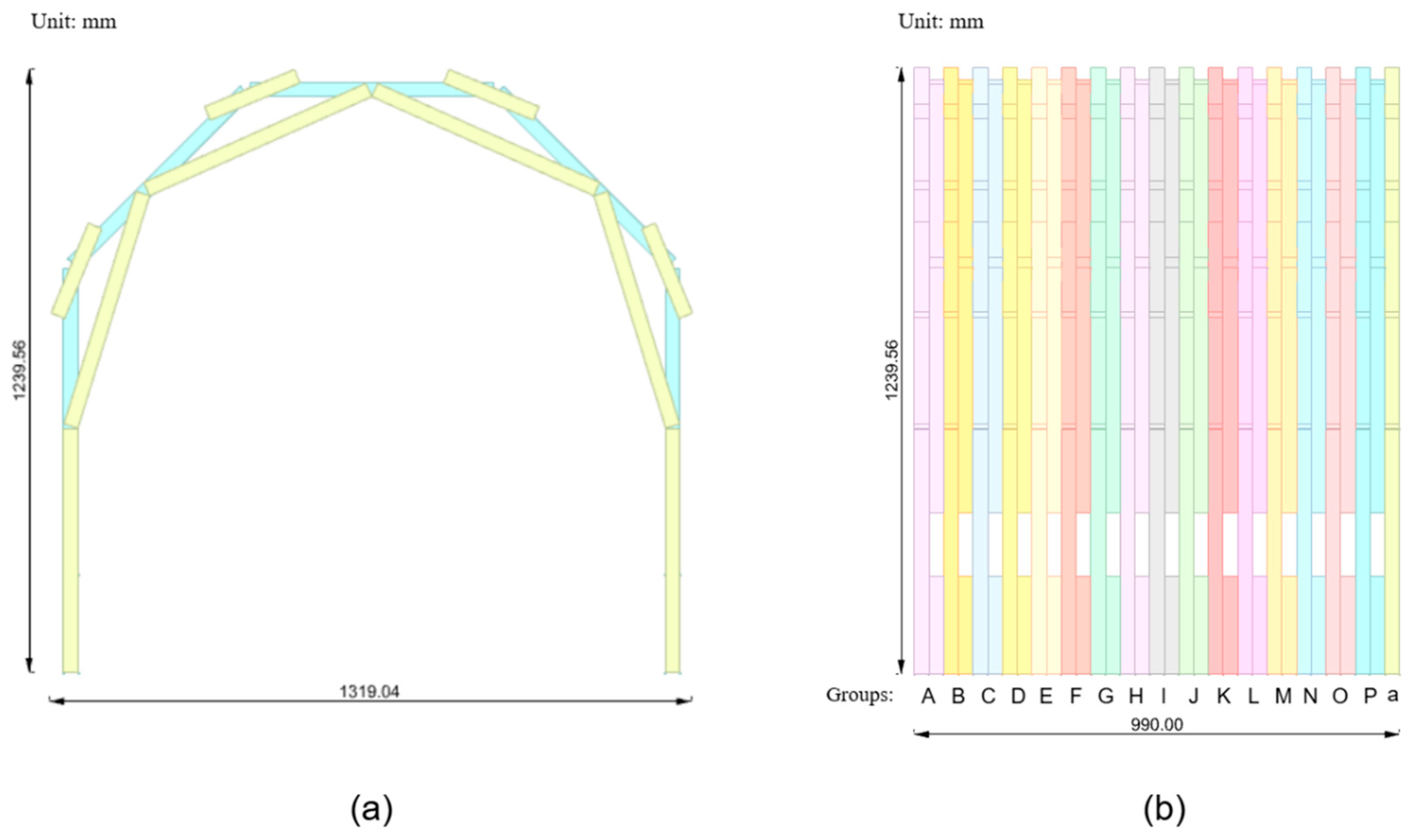
The target timber structure is a layered interlaced timber arch-shell (LITAS), characterized by a pointed arch geometry formed through interlocking multiple layers of screw-fastened timber elements. This configuration yields a self-stabilizing spatial structure with superior load-bearing capacity and lateral resistance [29]. Constrained by the robotic system’s maximum operational range, the structure measures 1.24 m in height and occupies a footprint of 1.18 m2, as illustrated in Figure 2. The material employed is Hinoki cypress (Chamaecyparis obtuse), a species widely used in Japanese timber constructions for its strength and durability [30]. The LITAS consists of 282 timber blocks and 512 self-tapping screws, arranged into 17 sequential groups (A–P) plus an additional preliminary layer (a). Each group incorporates two block lengths (500 mm and 200 mm) with a uniform cross-section of 30 mm × 30 mm. The parametric design process ensured structural stability and screw-fastening feasibility by defining the orientation and placement of each block while accounting for robotic reachability and screw insertion trajectories.
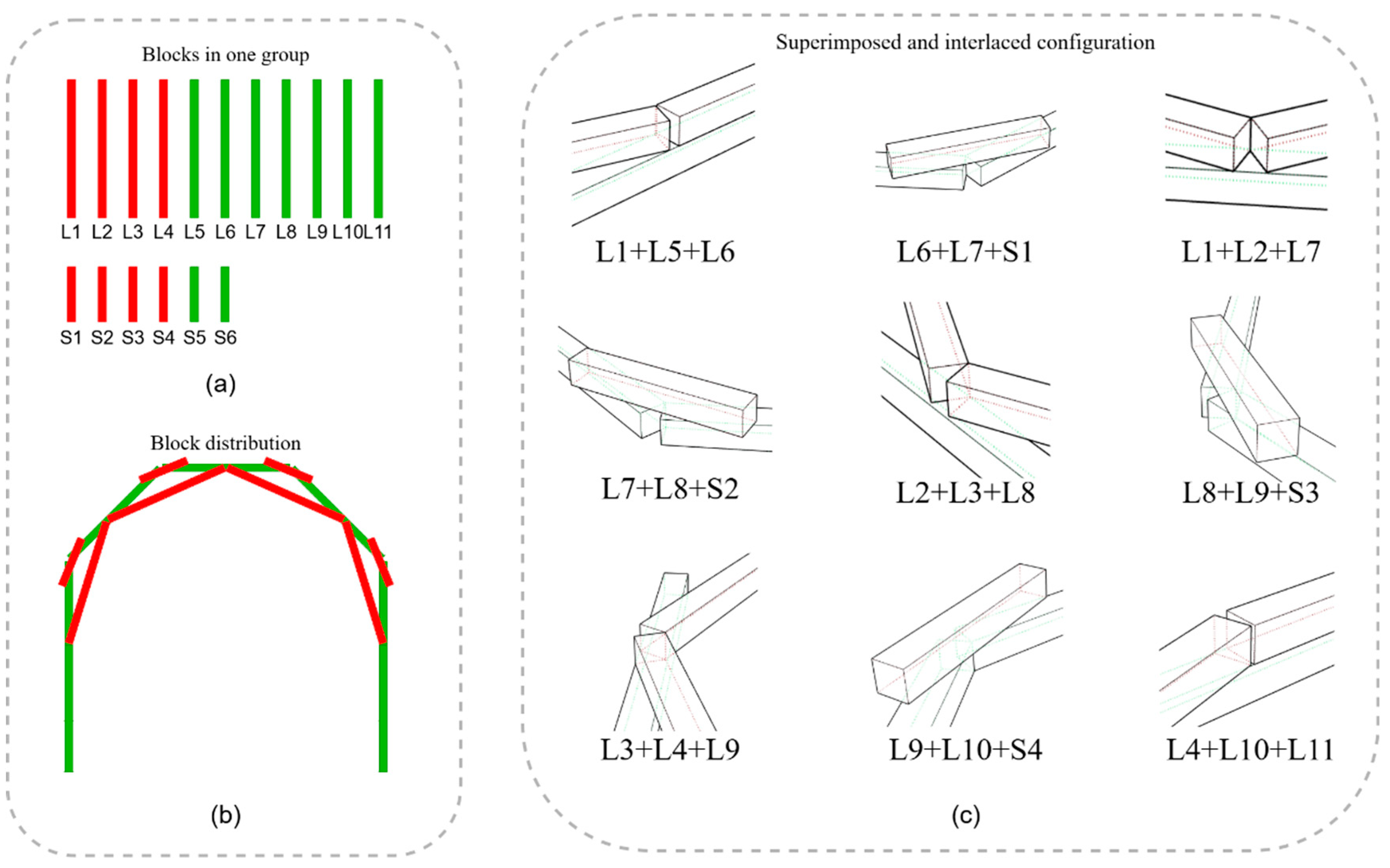
The structure’s assembly sequence replicates the superimposed and interlaced arrangement of these groups. Within each group, blocks serve either as primary load-bearing components or as stabilizing elements, with their positions determined through parametric optimization to balance load transfer and stiffness (Figure 3). This parametric modeling strategy provided both geometric definition and robotic constructability, ensuring a precise framework for subsequent automated assembly.

2.3. Life-Cycle Assessment Method

Life-cycle assessment (LCA) is a systematic methodology for identifying, quantifying, and evaluating the potential environmental impacts of a product, process, or service throughout its life cycle. ISO 14040 and ISO 14044 [31,32] provide the core methodological framework for conducting LCA studies. The present assessment focuses on the construction phase of the LITAS using a robotic construction system. While the methodological framework follows ISO 14040/44 and EN 15804 [33], this study extends its application to robotic timber assembly by defining the functional unit as the complete construction of a layered arch-shell and tailoring the system boundaries to construction-phase processes.

2.3.1. Functional Unit Definition

The functional unit for this LCA study is defined as the complete assembly of one LITAS structure with a footprint of 1.18 m2 and height of 1.24 m. This functional unit encompasses 282 timber blocks (40.96 kg total mass) and 512 self-tapping screws (2.43 kg), assembled using the robotic construction system. The reference flow includes all materials, energy, and auxiliary inputs required to construct one complete LITAS structure meeting the specified performance requirements. Unlike conventional LCA studies that often define functional units at the area of individual structure components, this study introduces a holistic functional unit encompassing the complete robotic assembly of a full-scale timber arch-shell. This definition extends the scope of construction-phase LCA to capture the integrated impacts of automated fastening workflows, thereby tailoring the framework to the specific context of robotic timber construction.

2.3.2. Boundary System

This study employs a cradle-to-site LCA framework. The system model applies the cut-off approach, with background data are sourced from the ecoinvent 3.9 database.
A1–A3 Raw material supply and manufacturing
These stages encompass raw material extraction, regional transportation, and processing for both timber blocks and self-tapping screws. This includes forest harvesting, sawing, and kiln-drying for lumber, as well as cold-forming, electroplating, and packaging for screws.
A4 Transport
Road freight exclusively is considered, encompassing ton-kilometer impacts across the supply chain: forest to sawmill, sawmill to the distribution warehouse, and distribution warehouse to the experimental site. Marine and air transport are excluded as all construction materials are domestically produced and procured within Japan.
A5 Construction and installation
This stage accounts for: electricity consumed by the robot and its controller, the electrical equivalent of compressed-air usage, energy consumed by the end-effector, energy demand of the lifting platform and 2% material losses on-site.
Exclusions
Capital equipment manufacturing and installation (robot, lifting mechanism, and end-effector) are excluded from A1–A3 due to data unavailability and limited analytical relevance. Use-phase (B1–B7) operational energy and end-of-life (C1–C4) processes are excluded, with the assessment focusing exclusively on material production and construction activities, and future dismantling scenarios too uncertain. Minor end-effector component replacements were excluded under cut-off approach, as their weight comprised less than 1% of the total material mass.

2.3.3. Construction-Phase Life-Cycle Inventory

The LCI phase involves systematic collection of input/output data for all processes within the system boundary. Primary data sources include detailed bills of materials for timber components, and energy consumption from robotic operations based on time-motion studies for assembly sequences. Secondary data from ecoinvent 3.9 database supplement primary data for background processes.
Bills of materials for LITAS
Table 1 presents the detailed life-cycle inventory of all materials used in the LITAS construction.
Energy consumption of Robotic construction system
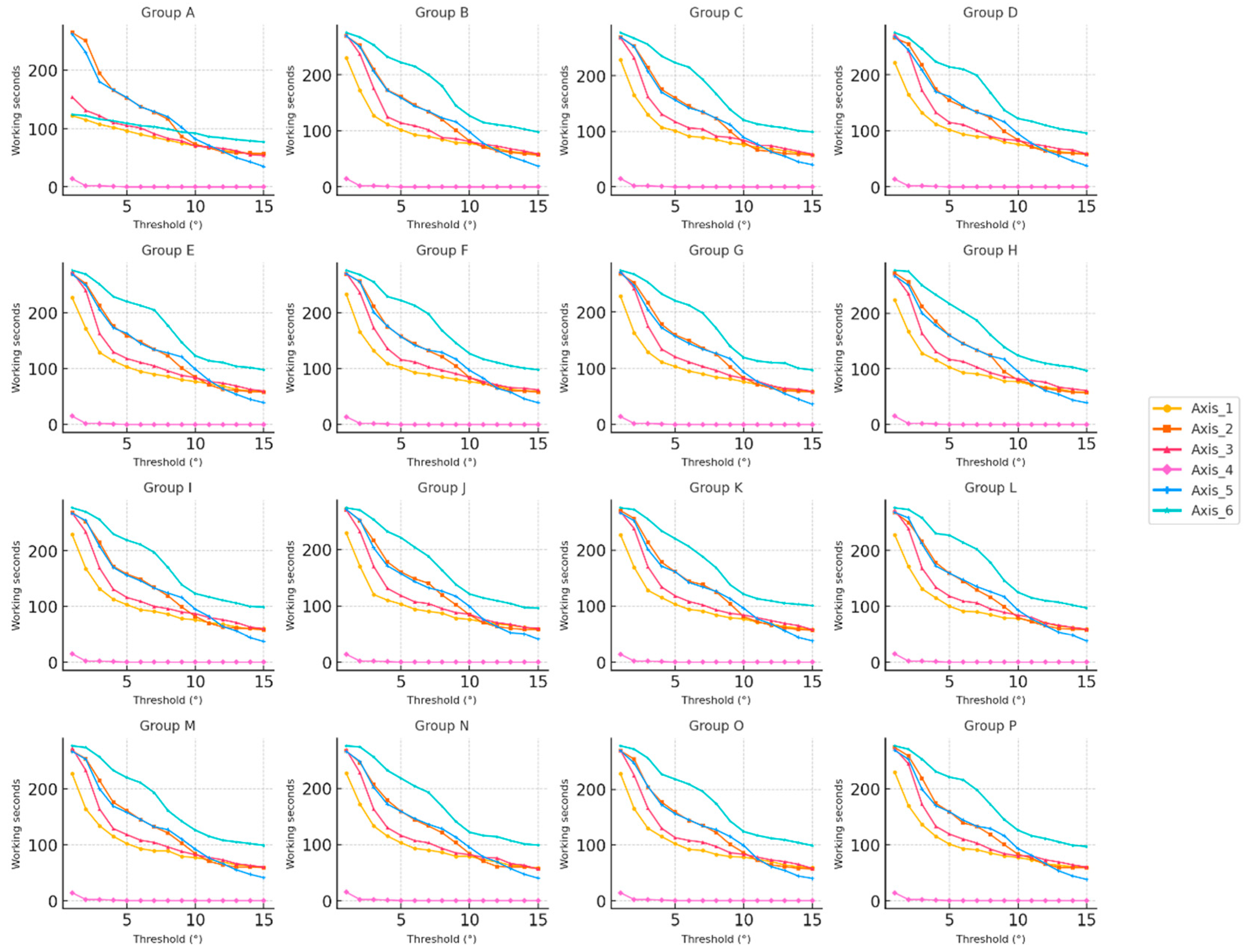
The energy consumption of the robot was calculated as the sum of the energy consumed by its six servo-driven axes, with the consumption of each axis directly related to its effective operating time [34,35]. To differentiate between “working” and “idle” states, effective operating time was defined as periods exhibiting angular displacement ≥ 1° within one-second intervals. A sensitivity analysis evaluated angular displacement thresholds ranging from 1° to 15°. The variation in effective operating time from Group A to Group P with respect to different angular thresholds is presented in Figure 4.
The threshold sensitivity analysis yielded the following results:
Axes 1–3 exhibit an approximately linear decrease in operating time with increasing thresholds, plateauing beyond 10°. This indicates movement concentration within the 5–10° range. Axis 4 exhibits negligible angular displacement throughout the task, with zero operating time, thus functioning as a non-participating axis. Axis 5 demonstrates maximum sensitivity to threshold changes, with a 50% reduction in operating time when the threshold increases from 1° to 10°, indicating its primary function in minor pose adjustments. Axis 6 exhibits a gradual decline in operating time with increasing thresholds, suggesting frequent medium- to large-scale pose transitions.
Balancing noise filtering against omission risk, a 5° threshold was selected to define effective operation for subsequent energy consumption calculations.
To integrate robotic assembly energy consumption into the unified life-cycle inventory, construction-phase energy is disaggregated into three components: robotic drive electricity (Erobot), compressed air electricity equivalent (Eair), and lifting platform electricity (Elift). Total energy consumption equals the sum of these three components.
Based on the preceding threshold sensitivity analysis, the effective duty cycle λ i for each robotic axis is determined, where t i w o r k and t t o t a l represent the effective operating time of the axis i and the total assembly time, respectively Equation (1).
λ i = t i w o r k t t o t a l
The robot’s electricity consumption is calculated by substituting the duty cycle into the rated operating power P i r u n and standby power P i i d l e (obtained from the manufacturer’s specifications), then summing the energy consumption across all six axes Equation (2).
E r o b o t = i = 1 6 λ i P i r u n + 1 λ i P i i d l e t t o t a l
Compressed air energy consumption Eair is calculated from the total air volume Vtot and the conversion coefficient Cair, whereas Elift is determined from the gravitational potential energy required for platform lifting, accounting for transmission efficiency. The total systems energy consumption is obtained by summing the individual contributions from the robot, compressed air system, and lifting platform Equation (3).
E t o t a l = E r o b o t + E a i r + E l i f t
Table 2 presents the electricity consumption of the robotic system, compressed air system, and lifting platform during each group’s assembly (A-P, a). Robotic system energy consumption was calculated using the aforementioned equations, while compressed air system and lifting platform energy consumption values were derived from manufacturer specifications.

3. Robotic Automation Construction

3.1. Robot Setup

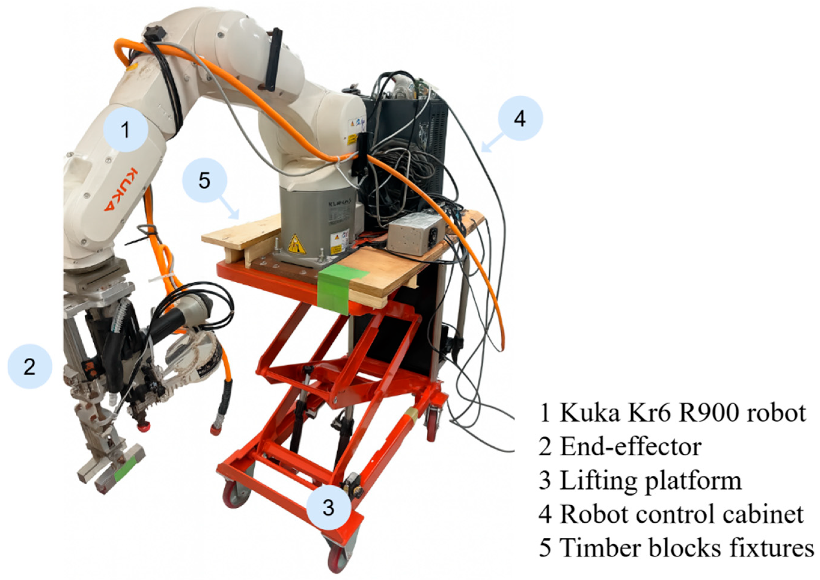
The robotic system setup represents a central methodological contribution of this study, as it integrates a vertically actuated robot, end-effector, and lifting platform into a unified system capable of fully automated LITAS assembly. The vertically mobile robotic construction system developed in this study comprises three integrated components: (1) a KUKA KR 6 R900 six-axis industrial robot as the core manipulator; (2) an electrically actuated lifting platform with a vertical travel range of 0.3 m to 1.8 m; and (3) a modular end-effector specifically designed for sequential gripping, transporting, and screw-fastening of timber elements (Figure 5). The robot arm, control cabinet, power supply, and pneumatic tubing are integrated onto the lifting platform, which employs a hydraulically actuated scissor-lift mechanism.
This platform enables synchronized elevation of the robot’s working plane, effectively extending the Kr 6’s native 900 mm vertical reach to approximately 2.4 m in the z-axis. The system design corresponds to the bottom-up, layer-by-layer assembly sequence inherent to the LITAS structure. Furthermore, the system achieves closed-loop coordination among the robot arm, lifting mechanism, and end-effector, enabling fully automated, continuous assembly of the entire LITAS without human intervention.
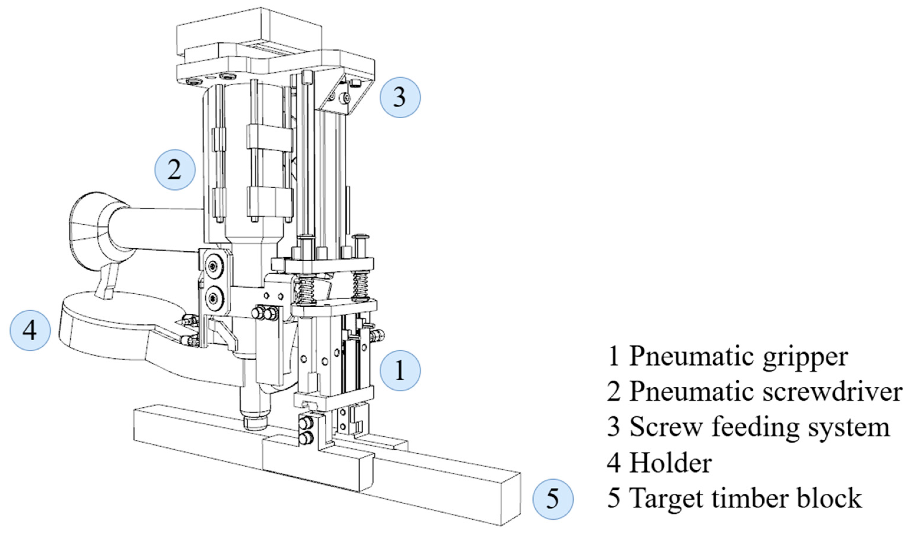
The end-effector replaces manual operations with mechanical automation. The end-effector incorporates the following components (Figure 6): (1) a pneumatic gripper for grasping, transporting, and positioning timber blocks with a 30 mm × 30 mm cross-section; (2) an automatic pneumatic screwdriver; (3) an integrated screw feeding system; and (4) a custom-designed holder that maintains the relative positions of the gripper and screwdriver, ensuring parallel operation and perpendicular orientation to the target timber block. This configuration prevents tool interference during operation and eliminates frequent end-effector reorientation. Additionally, during the screwing process, the pneumatic gripper stabilizes the timber, enhancing screw insertion precision.
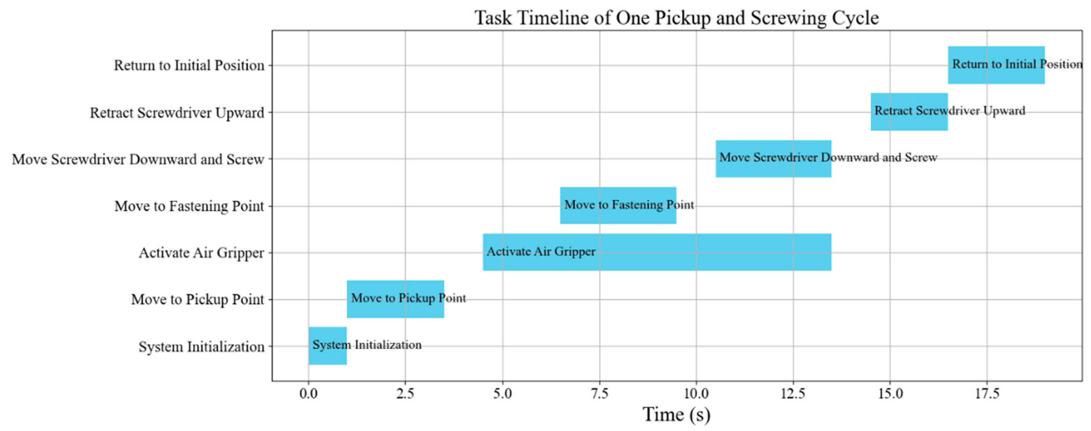
The end-effector completes single-screw fastening within 19 s per timber element, then immediately transitions to the next element, enabling continuous cyclic operation (Figure 7).

3.2. Robotic Construction Simulation and Robot Control

Using the KUKA|prc plug-in in Grasshopper, this study directly couples the parametric geometry of the LITAS with robotic assembly operations, enabling seamless translation from architectural models to robotic toolpaths. Path planning encompasses three primary operational steps: gripping, placing, and screw-driving.
(1)
Gripping: A robot-recognizable reference plane is generated on each timber block’s top surface. The calibrated offset between the screwdriver axis and gripper center enables single-step gripping pose determination. This approach eliminates frequent realignment during subsequent screwing operations caused by pose errors.
(2)
Placing: To prevent collisions between the target block and assembled components, the timber block is first positioned 100 mm above location, then lowered vertically to its final coordinate. This ensures a safe and linear trajectory.
(3)
Screw-driving: Experimental validation established an optimal insertion time of 0.5 s per self-tapping screw, balancing sufficient torque with maximum cycle efficiency.
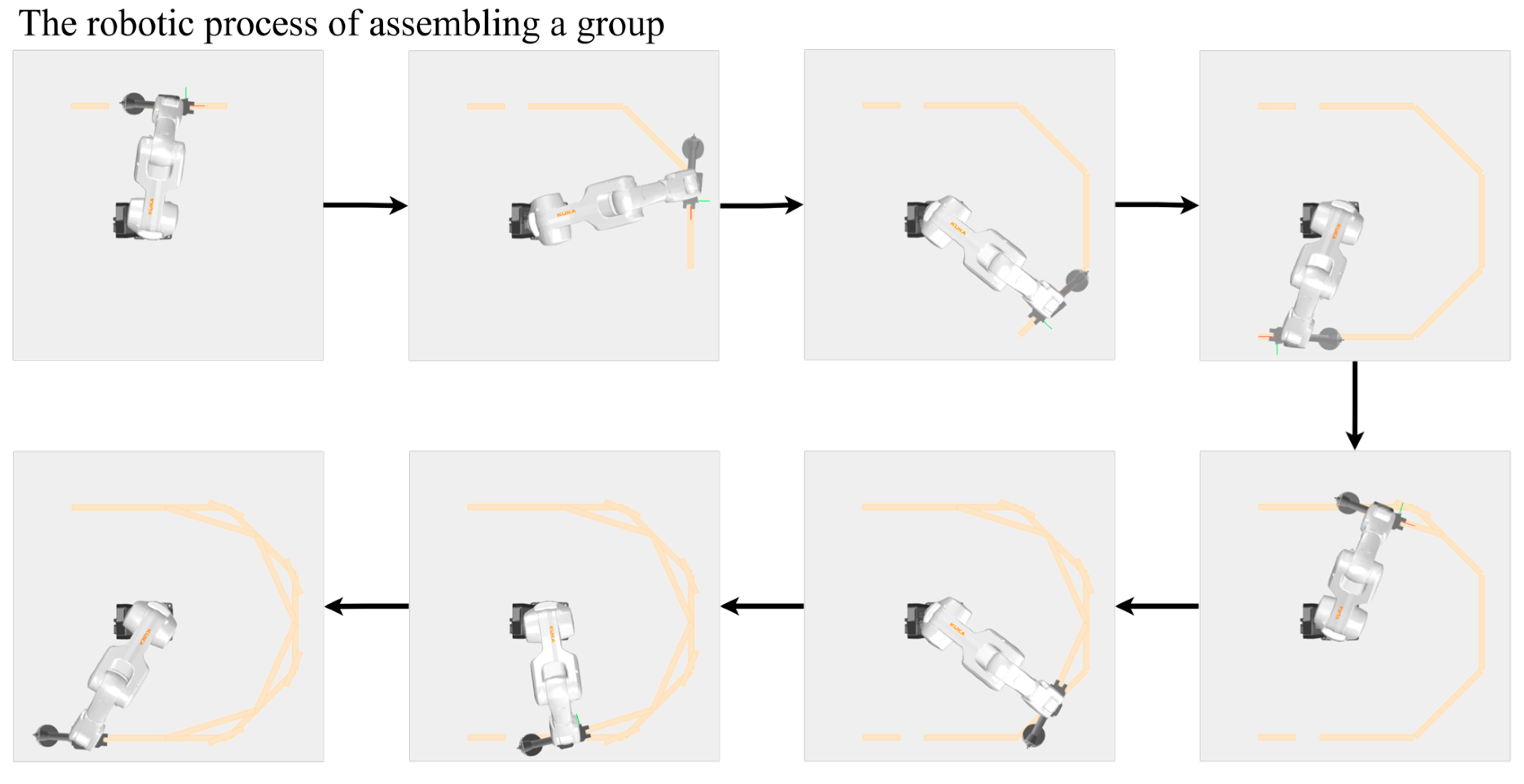
Each block assembly cycle follows a simulation-determined sequence. The robot initially approaches the designated picking position to retrieve the specified timber element, subsequently transferring it to the target coordinates for precise placement. Based on pre-programmed instructions, the system automatically determines the required screw quantity, then activates the screwdriver for fastening. Following fixation, the gripper releases the timber element, and the robot returns to its initial position, prepared for the next cycle. This cycle repeats until complete group assembly (Figure 8).
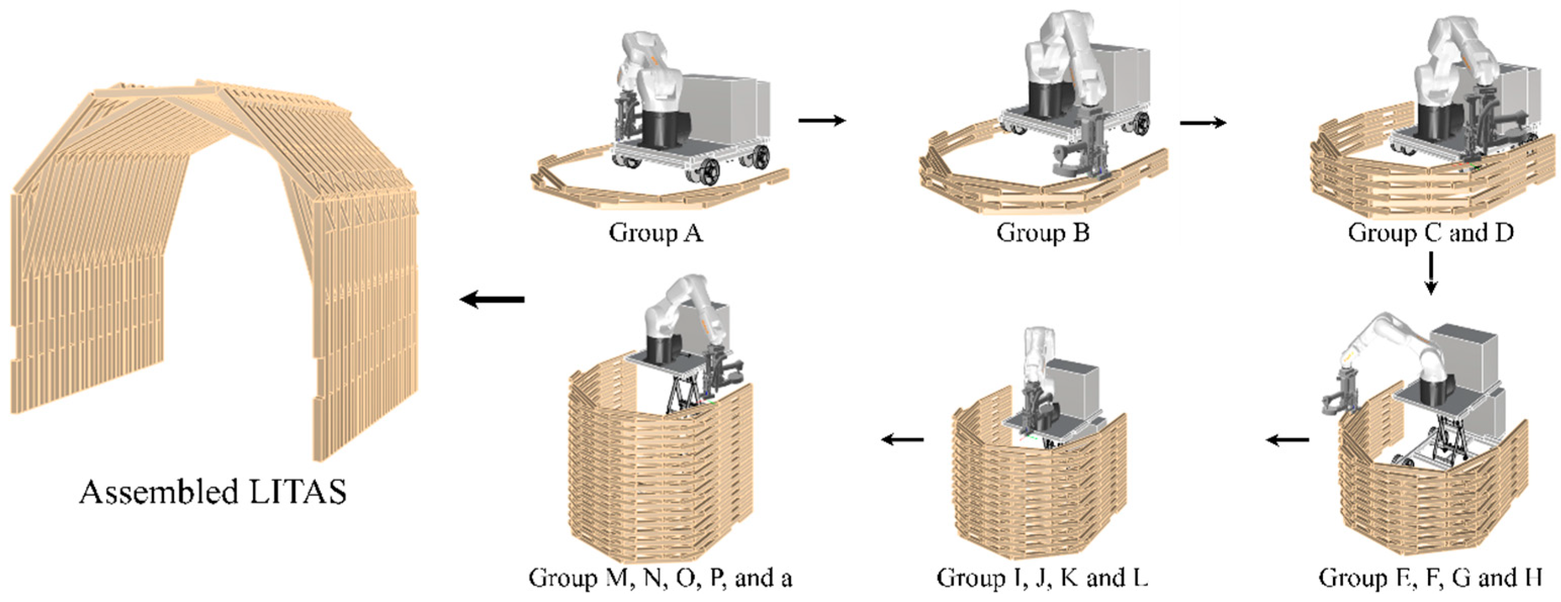
Upon completing each group’s assembly, the robot immediately proceeds to the next group using the same operational sequence, continuing until reaching the robotic arm’s operational limit. At this point, the lifting platform elevates the system to a new working height, enabling resumption of the cycle assembly process. This layer-by-layer progression continues until structure completion (Figure 9).

3.3. Robotic Construction System Assembly

This section details the assembly process and practical performance of the LITAS under experimental conditions. Prior to experimentation, the research team performed geometric calibration in the virtual environment to align the robot, lifting platform, block fixtures, end-effector, and target structure, ensuring digital-physical workspace consistency.
During the preparation phase, operators systematically verified correct positioning of all timber blocks within the block fixture area and confirmed the availability of all required self-tapping screws.
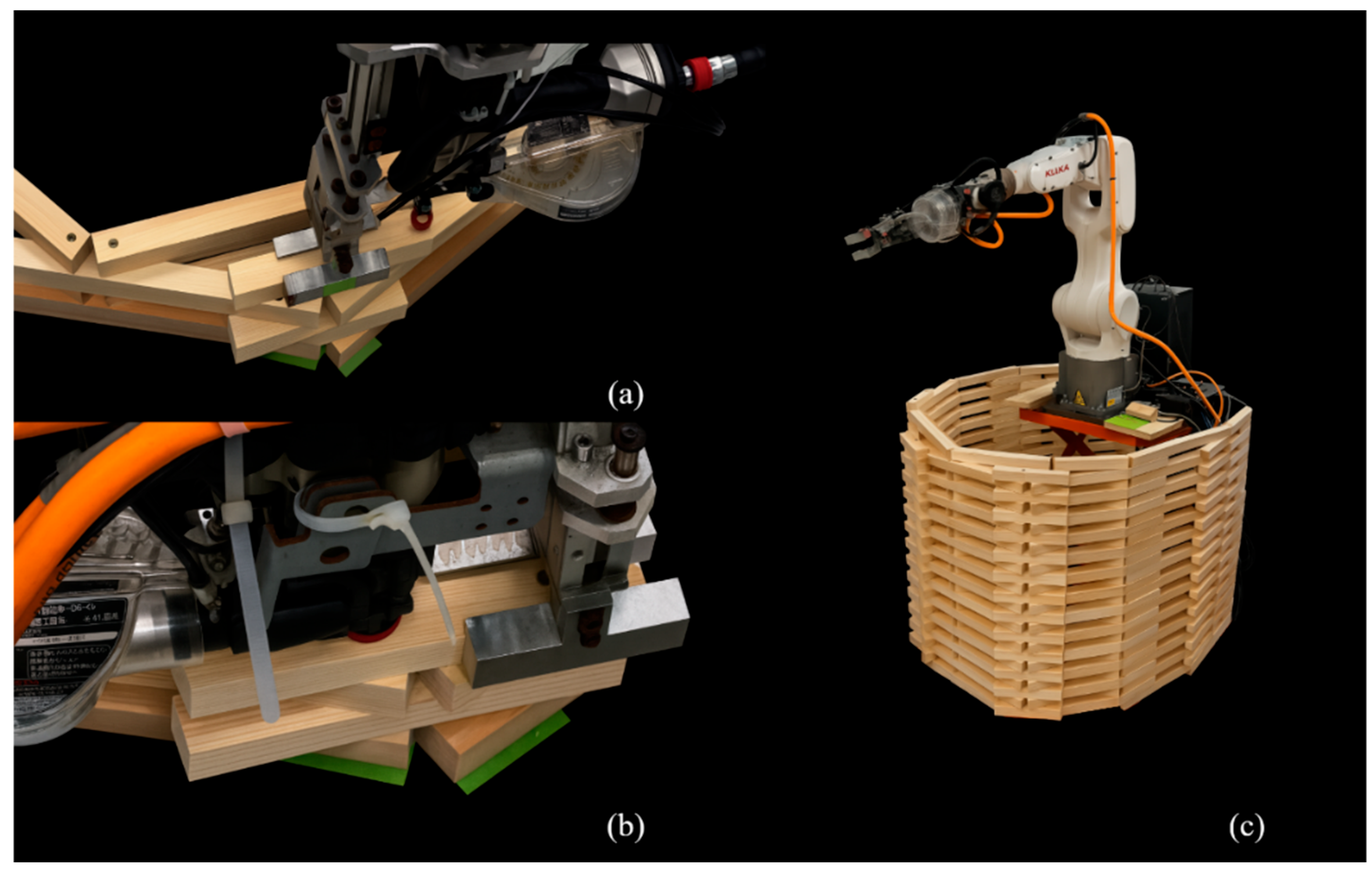
During assembly, the robot executed the predefined “gripping–placing–screwing” cycle (Figure 10), with screw quantities for each timber element automatically determined according to programmed specifications. Following the assembly logic, the system actuated the lifting platform after every two group installations, maintaining optical working height for subsequent assembly cycles.
Throughout the layer-by-layer construction, positional deviations of approximately 2–3 mm occurred in certain timber block due to thread-cutting debris, machining tolerances, and moisture-induced dimensional changes. To prevent error accumulation, on-site personnel continuously monitored the assembly accuracy, implementing real-time toolpath and layer height adjustments in Grasshopper to ensure geometric closure.
Through this closed-loop design-simulation-assembly integration, the robotic system successfully completed LITAS assembly, demonstrating the feasibility of combining digital parametric workflows with on-site adaptive correction for efficient robotic timber construction.

4. Results

First, the feasibility of the robotic system is visually demonstrated of the actual construction process. Second, the section quantifies the environmental performance of the robotic LITAS assembly on a cradle-to-site basis LCIA results are reported for the midpoint indicators required by EN 15804, with particular emphasis on the disaggregation of fossil, biogenic and land-use–related global warming potentials. The top 5 direct contributors within each process are identified and their relative shares are visualized. Third, the sensitivity of global warming potential to changes in component scale is examined through elasticity analysis. Finally, the accuracy and robustness of the proposed automated workflow are assessed by comparing the simulated assembly schedule with the time records of the laboratory experiment. The mean deviation and maximum deviation between simulated and observed cycle times are calculated for each assembly group (a, A–P). The implications of these findings for large-scale timber construction and future life-cycle optimization are further discussed.

4.1. Robotic Construction Assembly Results

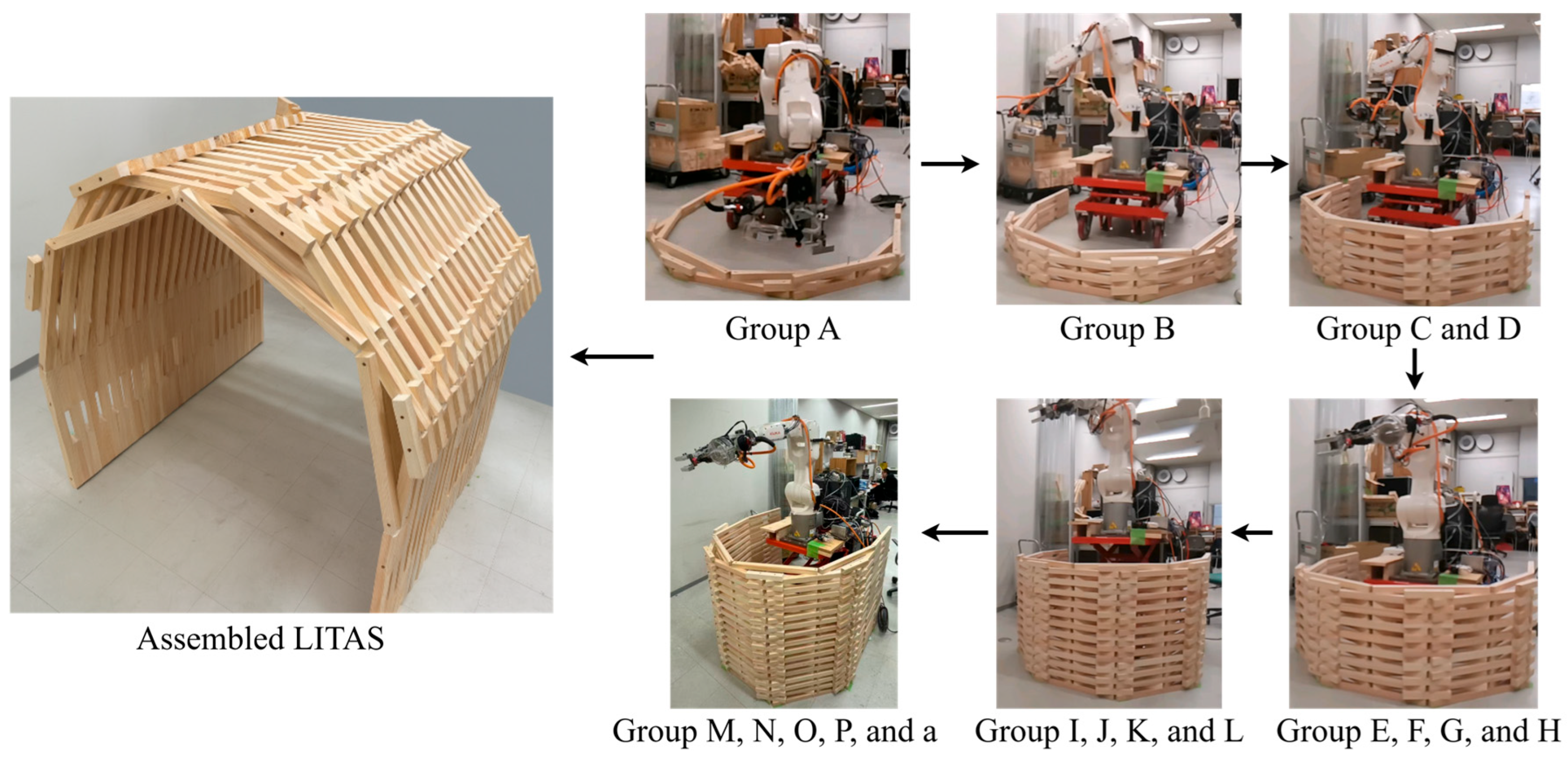
Figure 11 shows sequential photographs of the actual construction, beginning with the initial placement of timber blocks and continuing through the layer-by-layer assembly to the completed arch-shell. The images capture the continuous “gripping–placing–screwing” cycle executed by the robot and the progressive elevation achieved with the lifting platform. The final specimen demonstrates that the robotic workflow successfully reproduced the parametric design geometry without manual intervention. This visual evidence complements the subsequent quantitative analyses by confirming the practical reliability of the system.

4.2. Life-Cycle Impact Assessment (LCIA)

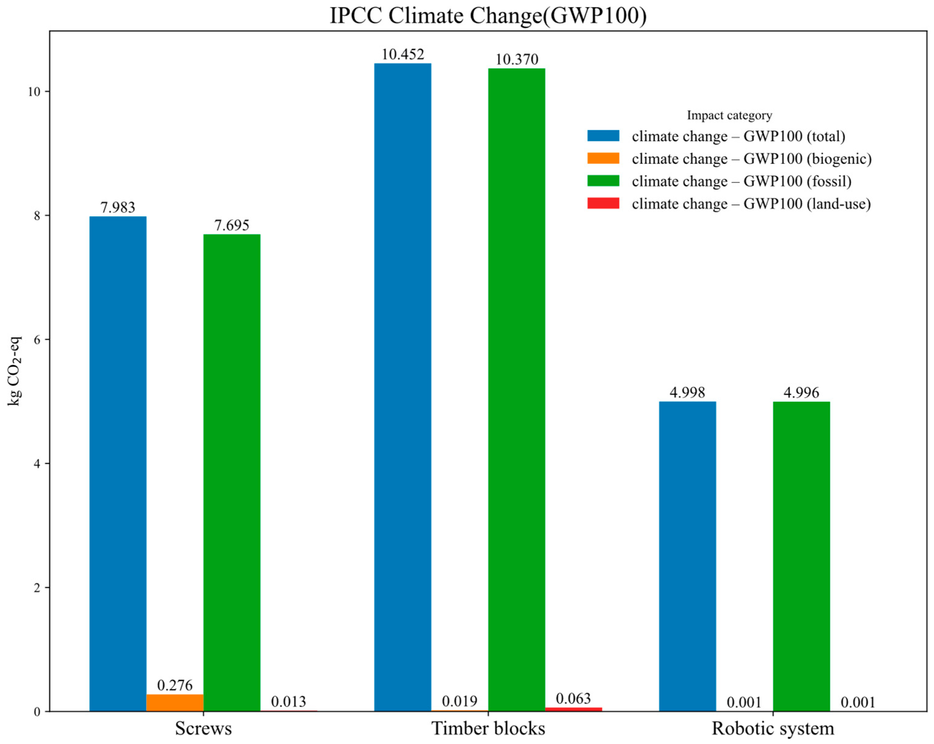
Environmental impacts are evaluated using IPCC 2021 [36] GWP100 method, focusing on climate change impacts. The assessment distinguishes between biogenic, fossil, and land-use related emissions following EN 15804 standards. Process contributions to climate change impacts are visualized in Figure 12.
Timber processing emerges as the largest source of greenhouse gas emissions, comprising 45% of total emissions. Steel production and electroplating for self-tapping screws contribute 34% of emissions, exhibiting the highest mass-specific emission intensity. Robotic system electricity consumption during assembly contributes 21% of emissions, confirming that automated assembly plays a secondary role compared to material-related emissions. Across all three categories, Fossil-GWP100 exceeds 96% of total emissions, while combined Biogenic and Land-use emissions remain below 2%. This reflects the database’s carbon-neutral treatment of timber carbon storage and minimal land-use-related emissions.
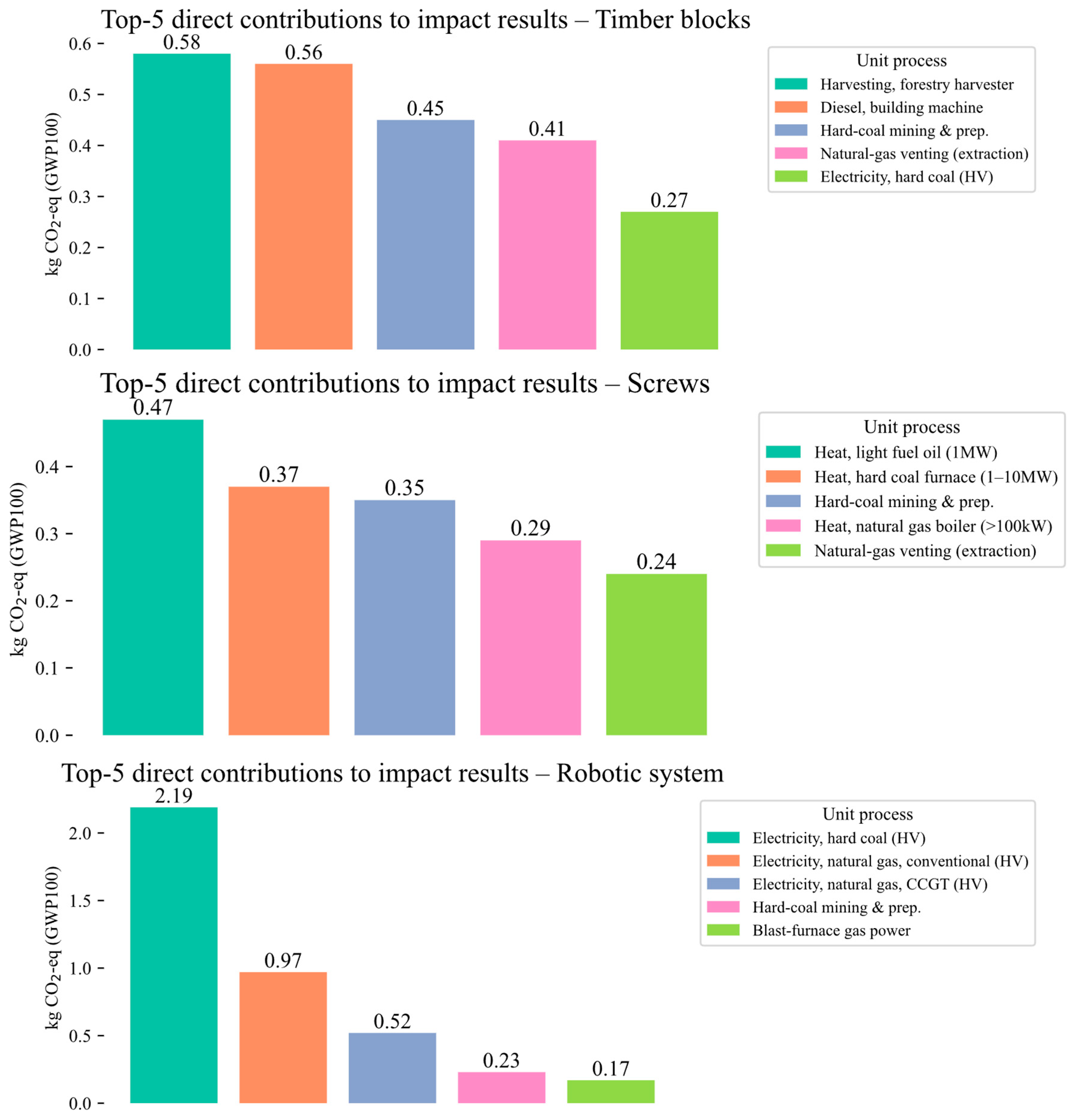
Analysis of the top five direct contributors reveals that carbon hotspots for all three primary components—screws, timber, and the robotic system are concentrated in fossil fuel-related processes (Figure 13).
Screw-related hotspots stem from fossil fuel heating during the electroplating and steel production stages. Timber hotspots arise from diesel combustion in forestry machinery and hard coal-based kiln drying electricity. Robotic system emissions are predominantly driven by Japan’s fossil fuel-intensive electricity grid. These findings indicate that embodied energy from material-related thermal and electricity sources significantly exceeds on-site assembly emissions.

4.3. Elasticity Analysis of Environmental Impact

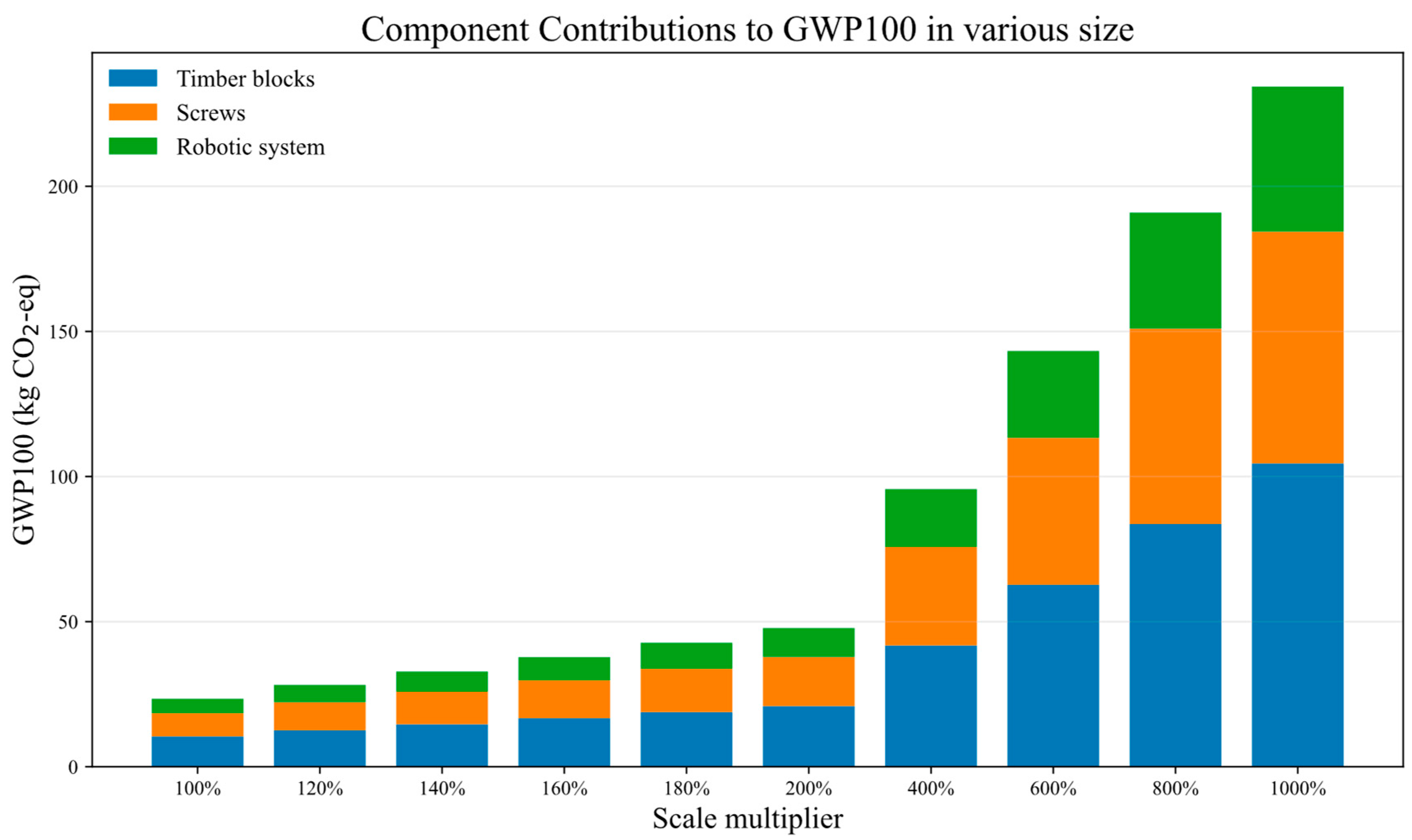
The elasticity analysis was conducted to evaluate the sensitivity of GWP100 emissions to variations in system component scales. This analysis examines how changes in the dimensions of system components affect the corresponding carbon emissions, with the elasticity coefficient measuring the proportional relationship between these changes. The study investigated component scaling across a range from baseline dimensions to a 1000% increase in size (Figure 14).
Proportional contributions to total emissions remain constant across construction scales: timber blocks contribute 44.6%, screws 34.1%, and the robotic system 21.3%. This indicates consistent prioritization for emission reduction efforts regardless of system scale. Component scale and total emissions exhibit a near-linear relationship, with system-wide scale elasticity coefficients approximating unity (Figure 15). Timber and robotic electricity consumption demonstrate average elasticities of 0.9999 ± 0.0006, indicating robust linearity. The screw component exhibits an overall linear trend (mean elasticity: 1.0019), with a minor super-proportional peak (1.0124) at 200% scale.
Emissions scale proportionally with measurable inputs, exhibiting direct size dependence. The system exhibits no significant threshold effects, with emission factors remaining stable across scaling operations. This validates model robustness throughout the examined size range. System scalability is maintained even when discrete transitions occur—such as the step increase in screw emissions near 200% scale—with component contributions to total GWP100 remaining constant.

4.4. Robotic Assembly Time Validation

Analysis of 17 assembly trials revealed that the actual construction times marginally exceeded numerical predictions, though deviations remained minimal (Figure 16). The mean absolute deviation between simulated and measured times was 11.19 s, with a maximum deviation of 12.83 s. Given an average cycle time of approximately 275 s per group, these deviations represent an error rate of 3–5%. These results demonstrate the system’s high temporal prediction accuracy and practical feasibility, confirming its stability and reliability under actual construction conditions.

5. Discussion

This study develops a vertically mobile robotic screw-fastening workflow for LITAS construction, achieving complete automated assembly while systematically quantifying construction-phase energy consumption and environmental impacts. Assembly time deviations remained minimal, validating the high reliability of both offline path planning and the duty cycle model. Construction-phase energy consumption remained low, with the robotic system comprising 21% and material-related emissions (timber and screws) accounting for 79%. Emission hotspots depend heavily on fossil fuel sources, notably hard coal-based electricity, boiler heating, and mining processes, highlighting the critical role of decarbonizing electricity grid and thermal energy in emission reduction strategies. Component-scale variation analysis reveals scale-invariant emission reduction hotspots. Timber constitutes the primary carbon source, followed by screws and robotic energy consumption. This prioritization hierarchy maximizes marginal benefits across all scales. Emission reduction strategies optimized at small scales transfer linearly to large-scale applications without requiring cost–benefit recalibration. Threshold effects exert minimal overall impact. While local step changes may induce temporary deviations in individual elasticity coefficients, they negligibly affect macro-scale proportions. Thus, discrete events demonstrate sensitivity only to micro-level factors without disrupting macro-level emission reduction priorities. These findings confirm the robustness and reliability of the LCA methodology.
By combining a stationary industrial robot with a lifting module, this study successfully constructed a timber arch-shell despite height constraints, establishing a replicable methodology for automating small- to medium-span timber structures. Furthermore, this study fills a critical data gap in cradle-to-site LCA for robotic screw-fastened timber construction, providing a benchmark for future energy optimization and carbon footprint assessments.
Based on these findings, the future research works are proposed: 1. Integration of force and vision sensors into the robotic end-effector for dynamic perception of timber tolerances and environmental disturbances, enabling adaptive closed-loop control; 2. Development of holistic carbon-optimization workflows integrating construction-phase energy efficiency with low-carbon electricity and sustainable supply chains; 3. Deployment of tracked mobile platforms with integrated lifting module for full-scale timber structures assembly, particularly in applications involving large spans or complex terrain. 4. Despite demonstrating stable automated assembly of the LITAS prototype, the current robotic system remains constrained by the intrinsic reach of the robot arm. The integrated lifting platform extends the vertical envelope and thus permits enlargement along the x-axis under a layer-by-layer stacking sequence. However, scaling in the z-axis direction (structural height) would require either robot with larger operational ranges or alternative construction logics that deviate from the current vertical stacking workflow. Future research will therefore focus on extending workspace mobility and exploring alternative robotic construction strategies to enable full-scale applications.

6. Conclusions

The findings of this work should be interpreted considering certain limitations. First, the LCA adopts a cradle-to-site boundary with a cut-off approach, excluding upstream processes such as the manufacturing of capital equipment (robot, lifting platform, and end-effector), plant infrastructure, and auxiliary services. Second, the results are based on a laboratory-scale assembly of an arch-shell structure with one robotic configuration. Although elasticity analysis indicates near-linear scalability, large-scale projects may be influenced by site logistics, construction tolerances, or alternative fastening techniques. These limitations underline the scope of the present study and suggest directions for further validation and extension.
This study proposes and validates a vertically mobile robotic screw-fastening workflow for the construction of a Layered Interlaced Timber Arch-Shell (LITAS). Through an integrated parametric design–simulation–fabrication workflow driving an industrial robotic arm combined with a lifting module, the system achieves fully automated timber construction while providing the first comprehensive quantification of both robotic-phase energy consumption and cradle-to-site life-cycle impacts. Experimental results confirm the system’s stability and reliability under real-world construction conditions. Life-cycle assessment reveals robotic operations contribute only 21% of carbon emissions, while material-related emissions (from timber and screws) dominating at 79%, with emission hotspots concentrated in fossil-based electricity and thermal energy processes. This dataset addresses critical gaps in the life-cycle inventory for robotic screw-fastened timber construction, providing a benchmark for future energy optimization and carbon footprint analysis. The findings demonstrate the feasibility of robotic screw-fastened timber construction and its significant emission reduction potential for small- to medium-scale projects, establishing a replicable technological pathway and research framework to advance intelligent and low-carbon transformation in construction.

Author Contributions

Conceptualization, Y.L.; methodology, Y.L. and K.B.; software, Y.L. and K.B.; validation, Y.L. and K.B.; formal analysis, Y.L.; investigation, Y.L. and K.B.; resources, Y.L.; data curation, Y.L.; Writing—Original Draft Preparation, Y.L.; Writing—Review and Editing, Y.L.; Visualization, Y.L.; Supervision, H.F.; Project Administration, H.F.; Funding Acquisition, H.F. All authors have read and agreed to the published version of the manuscript.

Funding

This research received no external funding.

Data Availability Statement

The data presented in this study is available on request from the authors.

Conflicts of Interest

The authors declare no conflicts of interest.

References

  1. United Nations Environment Programme. Building Materials and the Climate: Constructing a New Future; United Nations: Nairobi, Kenya, 2023; ISBN 978-92-807-4064-6. [Google Scholar]
  2. Sizirici, B.; Fseha, Y.; Cho, C.-S.; Yildiz, I.; Byon, Y.-J. A Review of Carbon Footprint Reduction in Construction Industry, from Design to Operation. Materials 2021, 14, 6094. [Google Scholar] [CrossRef] [PubMed]
  3. Howard, C.; Dymond, C.C.; Griess, V.C.; Tolkien-Spurr, D.; Van Kooten, G.C. Wood Product Carbon Substitution Benefits: A Critical Review of Assumptions. Carbon Balance Manag. 2021, 16, 9. [Google Scholar] [CrossRef]
  4. Winchester, N.; Reilly, J.M. The Economic and Emissions Benefits of Engineered Wood Products in a Low-Carbon Future. Energy Econ. 2020, 85, 104596. [Google Scholar] [CrossRef]
  5. Leskinen, P.; Cardellini, G.; González-García, S.; Hurmekoski, E.; Sathre, R.; Seppälä, J.; Smyth, C.; Stern, T.; Verkerk, P.J. Substitution Effects of Wood-Based Products in Climate Change Mitigation; From Science to Policy; European Forest Institute: Joensuu, Finland, 2018. [Google Scholar]
  6. Falk, R. Wood as a Sustainable Building Material. In Wood Handbook: Wood as an Engineering Material: Chapter 1; U.S. Department of Agriculture, Forest Service, Forest Products Laboratory: Madison, WI, USA, 2010. [Google Scholar]
  7. Brozovsky, J.; Labonnote, N.; Vigren, O. Digital Technologies in Architecture, Engineering, and Construction. Autom. Constr. 2024, 158, 105212. [Google Scholar] [CrossRef]
  8. Biswas, H.K.; Sim, T.Y.; Lau, S.L. Impact of Building Information Modelling and Advanced Technologies in the AEC Industry: A Contemporary Review and Future Directions. J. Build. Eng. 2024, 82, 108165. [Google Scholar] [CrossRef]
  9. Nguyen, T.D.; Adhikari, S. The Role of BIM in Integrating Digital Twin in Building Construction: A Literature Review. Sustainability 2023, 15, 10462. [Google Scholar] [CrossRef]
  10. García De Soto, B.; Agustí-Juan, I.; Hunhevicz, J.; Joss, S.; Graser, K.; Habert, G.; Adey, B.T. Productivity of Digital Fabrication in Construction: Cost and Time Analysis of a Robotically Built Wall. Autom. Constr. 2018, 92, 297–311. [Google Scholar] [CrossRef]
  11. Pajonk, A.; Prieto, A.; Blum, U.; Knaack, U. Multi-Material Additive Manufacturing in Architecture and Construction: A Review. J. Build. Eng. 2022, 45, 103603. [Google Scholar] [CrossRef]
  12. Takva, Ç.; Top, S.M.; Gökgöz, B.İ.; Gebel, Ş.; İlerisoy, Z.Y.; İlcan, H.; Şahmaran, M. Applicability of 3D Concrete Printing Technology in Building Construction with Different Architectural Design Decisions in Housing. J. Build. Eng. 2024, 98, 111257. [Google Scholar] [CrossRef]
  13. Chea, C.P.; Bai, Y.; Pan, X.; Arashpour, M.; Xie, Y. An Integrated Review of Automation and Robotic Technologies for Structural Prefabrication and Construction. Transp. Saf. Environ. 2020, 2, 81–96. [Google Scholar] [CrossRef]
  14. Adekunle, P.; Aigbavboa, C.; Otasowie, O.K.; Adekunle, S. Benefits of Robotic Utilization in the Prefabricated Construction Industry. In Proceedings of the 31st Annual Conference of the International Group for Lean Construction, Lille, France, 26 June–2 July 2023; pp. 746–754. [Google Scholar]
  15. Li, Y.; Zhang, Y.; Pan, A.; Han, M.; Veglianti, E. Carbon Emission Reduction Effects of Industrial Robot Applications: Heterogeneity Characteristics and Influencing Mechanisms. Technol. Soc. 2022, 70, 102034. [Google Scholar] [CrossRef]
  16. Willmann, J.; Knauss, M.; Bonwetsch, T.; Apolinarska, A.A.; Gramazio, F.; Kohler, M. Robotic Timber Construction—Expanding Additive Fabrication to New Dimensions. Autom. Constr. 2016, 61, 16–23. [Google Scholar] [CrossRef]
  17. Liu, Y.; Alias, A.H.; Haron, N.A.; Bakar, N.A.; Wang, H. Robotics in the Construction Sector: Trends, Advances, and Challenges. J. Intell. Robot. Syst. 2024, 110, 72. [Google Scholar] [CrossRef]
  18. Wagner, H.J.; Alvarez, M.; Groenewolt, A.; Menges, A. Towards Digital Automation Flexibility in Large-Scale Timber Construction: Integrative Robotic Prefabrication and Co-Design of the BUGA Wood Pavilion. Constr. Robot. 2020, 4, 187–204. [Google Scholar] [CrossRef]
  19. Wagner, H.J.; Alvarez, M.; Kyjanek, O.; Bhiri, Z.; Buck, M.; Menges, A. Flexible and Transportable Robotic Timber Construction Platform—TIM. Autom. Constr. 2020, 120, 103400. [Google Scholar] [CrossRef]
  20. Lai, Z.; Xiao, Y.; Chen, Z.; Li, H.; Huang, L. Preserving Woodcraft in the Digital Age: A Meta-Model-Based Robotic Approach for Sustainable Timber Construction. Buildings 2024, 14, 2900. [Google Scholar] [CrossRef]
  21. Kramberger, A.; Kunic, A.; Iturrate, I.; Sloth, C.; Naboni, R.; Schlette, C. Robotic Assembly of Timber Structures in a Human-Robot Collaboration Setup. Front. Robot. AI 2022, 8, 768038. [Google Scholar] [CrossRef] [PubMed]
  22. Yang, X.; Amtsberg, F.; Sedlmair, M.; Menges, A. Challenges and Potential for Human–Robot Collaboration in Timber Prefabrication. Autom. Constr. 2024, 160, 105333. [Google Scholar] [CrossRef]
  23. Apolinarska, A.A.; Pacher, M.; Li, H.; Cote, N.; Pastrana, R.; Gramazio, F.; Kohler, M. Robotic Assembly of Timber Joints Using Reinforcement Learning. Autom. Constr. 2021, 125, 103569. [Google Scholar] [CrossRef]
  24. Naboni, R.; Kunic, A.; Kramberger, A.; Schlette, C. Design, Simulation and Robotic Assembly of Reversible Timber Structures. Constr. Robot. 2021, 5, 13–22. [Google Scholar] [CrossRef]
  25. Kunic, A.; Naboni, R.; Kramberger, A.; Schlette, C. Design and Assembly Automation of the Robotic Reversible Timber Beam. Autom. Constr. 2021, 123, 103531. [Google Scholar] [CrossRef]
  26. Chai, H.; So, C.; Yuan, P.F. Manufacturing Double-Curved Glulam with Robotic Band Saw Cutting Technique. Autom. Constr. 2021, 124, 103571. [Google Scholar] [CrossRef]
  27. Leng, Y.; Shi, X.; Fukuda, H.; Kalachev, A.; Wan, D. Automated Construction for Human–Robot Interaction in Wooden Buildings: Integrated Robotic Construction and Digital Design of iSMART Wooden Arches. J. Field Robot. 2023, 40, 810–827. [Google Scholar] [CrossRef]
  28. Reisach, D.; Schütz, S.; Willman, J.; Schneider, S. Digital Fabrication for Circular Timber Construction: A Case Study. J. Circ. Econ. 2024, 1, 1–18. [Google Scholar] [CrossRef]
  29. Zhao, S.; Guo, F.; Zhao, J.; Yang, S.; He, F.; Liu, H.; Chen, Z. Investigation of the In-Plane Mechanical Behavior of Timber and Steel–Timber Composite Arches. Structures 2023, 57, 105267. [Google Scholar] [CrossRef]
  30. Yokoyama, M.; Gril, J.; Matsuo, M.; Yano, H.; Sugiyama, J.; Clair, B.; Kubodera, S.; Mistutani, T.; Sakamoto, M.; Ozaki, H.; et al. Mechanical Characteristics of Aged Hinoki Wood from Japanese Historical Buildings. Comptes Rendus Phys. 2009, 10, 601–611. [Google Scholar] [CrossRef]
  31. ISO 14040:2006; Environmental Management—Life Cycle Assessment—Principles and Framework. International Organization for Standardization: Geneva, Switzerland, 2006.
  32. ISO 14044:2006; Environmental Management—Life Cycle Assessment—Requirements and Guidelines. International Organization for Standardization: Geneva, Switzerland, 2006.
  33. EN 15804:2012+A2:2019; Sustainability of Construction Works—Environmental Product Declarations—Core Rules for the Product Category of Construction Products. European Committee for Standardization: Brussels, Belgium, 2019.
  34. Rassolkin, A.; Hoimoja, H.; Teemets, R. Energy Saving Possibilities in the Industrial Robot IRB 1600 Control. In Proceedings of the 2011 7th International Conference-Workshop Compatibility and Power Electronics (CPE), Tallinn, Estonia, 1–3 June 2011; pp. 226–229. [Google Scholar]
  35. Paryanto; Brossog, M.; Kohl, J.; Merhof, J.; Spreng, S.; Franke, J. Energy Consumption and Dynamic Behavior Analysis of a Six-Axis Industrial Robot in an Assembly System. Procedia CIRP 2014, 23, 131–136. [Google Scholar] [CrossRef]
  36. IPCC. Climate Change 2021: The Physical Science Basis. Contribution of Working Group I to the Sixth Assessment Report of the Intergovernmental Panel on Climate Change; Masson-Delmotte, V., Zhai, P., Pirani, A., Connors, S.L., Péan, C., Berger, S., Caud, N., Chen, Y., Goldfarb, L., Gomis, M.I., et al., Eds.; Cambridge University Press: Cambridge, UK; New York, NY, USA, 2021. [Google Scholar] [CrossRef]
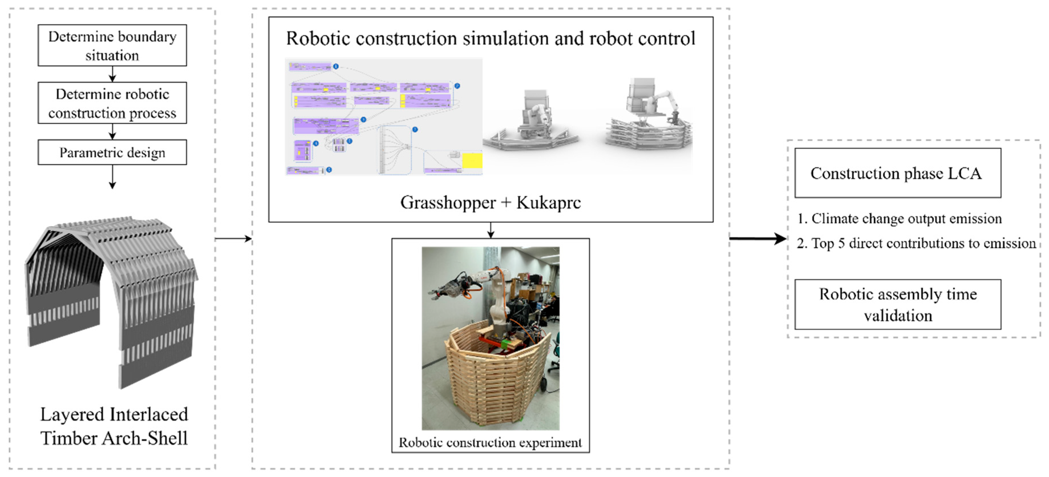
Figure 1. Workflow with computational design, construction workflow and LCA.
Buildings 15 03186 g001
Figure 2. Illustration of objective LITAS: (a) the front view, where different colors indicate different layers; (b) the right view and 16 groups from A to P and extra Group a.
Buildings 15 03186 g002
Figure 3. (a) Blocks used in one group; (b) Distribution of load-bearing components (green) and stabilizing elements (red); (c) Superimposed and interlaced configuration.
Buildings 15 03186 g003
Figure 4. Threshold sensitivity of axis activity across assembly groups.
Buildings 15 03186 g004
Figure 5. The vertically mobile robotic construction system that has been used for LITAS assembly in this study.
Buildings 15 03186 g005
Figure 6. End-effector with two main components: (1) Pneumatic Gripper; (2) Pneumatic screwdriver, and three auxiliary components: (3) Screw feeding system; (4) Holder; (5) Target timber block.
Buildings 15 03186 g006
Figure 7. The end-effector operational steps.
Buildings 15 03186 g007
Figure 8. Process of assembling a group of LITAS.
Buildings 15 03186 g008
Figure 9. The assembled LITAS by robot comprises Groups A to Group a.
Buildings 15 03186 g009
Figure 10. (a) Grip-place of timber block; (b) Screwing; (c) Assembled LITAS.
Buildings 15 03186 g010
Figure 11. Actual robotic construction of the LITAS from initial placement to final completion.
Buildings 15 03186 g011
Figure 12. Output emissions of each process.
Buildings 15 03186 g012
Figure 13. The top five emission contributors for each process.
Buildings 15 03186 g013
Figure 14. Emission composition for buildings of different sizes.
Buildings 15 03186 g014
Figure 15. Emission elasticity coefficients for buildings of different sizes.
Buildings 15 03186 g015
Figure 16. Simulated and measured construction time of each group.
Buildings 15 03186 g016
Table 1. All materials used in LITAS construction.
MaterialsItemWeight (kg)
Cypress blocks (500 mm)18233.58
Cypress blocks (200 mm)1007.38
M4 self-tapping screws5122.43
Table 2. Electricity consumption of the robotic system.
GroupRobot (kWh)Compressor (kWh)Lift-Platform (kWh)Total (kWh)
A0.360.0080.020.391
B0.440.011 0.451
C0.440.011 0.451
D0.430.011 0.441
E0.440.0110.020.471
F0.450.011 0.461
G0.440.011 0.451
H0.450.011 0.461
I0.430.0110.020.461
J0.440.011 0.451
K0.450.011 0.461
L0.440.011 0.451
M0.450.0110.020.481
N0.430.011 0.441
O0.440.011 0.451
P0.450.011 0.461
a0.210.0080.020.238
Disclaimer/Publisher’s Note: The statements, opinions and data contained in all publications are solely those of the individual author(s) and contributor(s) and not of MDPI and/or the editor(s). MDPI and/or the editor(s) disclaim responsibility for any injury to people or property resulting from any ideas, methods, instructions or products referred to in the content.