Article

Effects of Hydraulic Materials on the Performance Evolution of Carbonated High-Volume Magnesium Slag Mortars

School of Human Settlements and Civil Engineering, Xi’an Jiaotong University, Xi’an 710049, China
*
Author to whom correspondence should be addressed.
Buildings 2025, 15(17), 3062; https://doi.org/10.3390/buildings15173062
Submission received: 15 July 2025 / Revised: 17 August 2025 / Accepted: 22 August 2025 / Published: 27 August 2025

Abstract

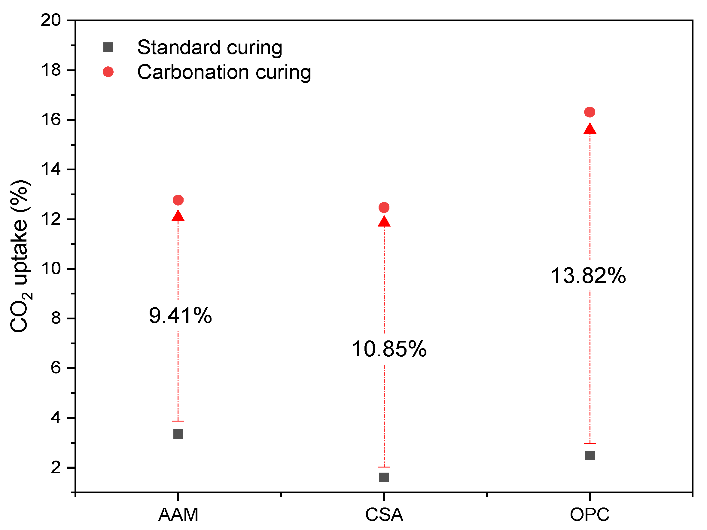
Magnesium slag (MS) is a solid by-product during magnesium production using the Pidgeon process. Around 5–6 million tons of magnesium slag was produced in China in 2023, which accounted for 83% of the total disposal of magnesium slag worldwide. To explore the innovative and high-end application of MS in building materials, this study investigated the preparation of calcium carbonate cementitious composites produced by high-volume (80%) MS and 20% of traditional ordinary Portland cement (OPC), low-carbon cement–calcium sulfoaluminate cement (CSA), or green cement–alkali-activated materials after CO2 curing. The effects of OPC, CSA, and AAM on the performance evolution of MS blends before and after carbonation curing were analyzed. The results indicated that AAM contributed to a superior initial strength (7.38 MPa) of MS composites after standard curing compared to OPC (1.18 MPa) and CSA (2.72 MPa). However, the lack of large pores (around 1000 nm) in the AAM-MS binder caused the slowest CO2 penetration during the carbonation curing period compared to the OPC- and CSA-blended samples. Less than 3 days were required for the full carbonation of the CSA- and OPC-blended MS mortar, while 7 days were required for the AAM blends. After carbonation, the OPC-blended MS exhibited the highest strength performance of 51.58 MPa, while 21.38 MPa and 9.3 MPa were reached by the AAM- and CSA-blended MS mortars, respectively. OPC-blended MS composites exhibited the highest CO2 uptake of 13.82% compared to the CSA (10.85%) and AAM (9.41%) samples. The leaching of Hg was slightly higher than the limit (<50 µg/L) in all MS mortars, which should be noticed in practical application.

1. Introduction

Ordinary Portland cement-based composites are the most intensively applied materials in engineering constructions [1]. Cement consumption worldwide reached 4.1 billion tons in 2023 [2]. Consequently, a large amount of CO2 was released during cement and building materials production, while a huge amount of natural resources, such as clay and limestone, are consumed every year (IEA). The CO2 emissions by building materials manufacturers have accounted for almost 8% of the global total emissions [3]. Many studies have been conducted to reduce the consumption of cement clinker, for example, the utilization of supplementary cementitious materials (SCMs) to replace cement in concrete, producing cement clinker with low-quality materials, and the production of building materials with innovative low-carbon technologies [4,5,6].
Carbonation curing has been applied in the production of building materials for decades [7], especially for the fast curing of pre-cast concrete structures [8]. Cement clinker and hydration products can be reacted with carbon dioxide (CO2) to form large amounts of calcium carbonate [9]. During the carbonation process of cement-based pre-cast concrete, the hydration of cement clinker can be improved significantly, while the precipitation of calcium carbonate was proved to effectively fill the pores of concrete [10]. Consequently, the fast strength development of concrete at early ages can be achieved [7]. In addition, the CO2 can be permanently stored in calcium carbonate polymorphs. In recent years, the applications of carbonation curing technology have been expanded to the field of valorization and the high-end application of alkaline solid wastes. Some alkaline solid wastes containing calcium oxide, calcium hydroxide, and calcium silicate-based phases showed high reactivity with the presence of CO2. The precipitation of calcium carbonate and other silica-alumina gel can provide a high reactivity to carbonated solid wastes in cement-based systems [11,12,13], which have been studied for their application as a new stream of SCMs in building materials. Furthermore, the precipitation of calcium carbonate during carbonation curing could play the role of the cementitious material. In Mo’s study, steel slag was applied as the main part of a binder to produce low-carbon building materials with a low content of cement, which gave a superior mechanical performance of composites [14,15]. The application of hydraulic materials provides a possibility to mold carbonation binders as usual cement concrete, which could be more efficient in producing shaped building materials than compressed modeling. Liu et al. also confirmed the cementitious ability of calcium carbonate from carbonation reaction, and the application of a low amount of a binding material, such as ordinary Portland cement, effectively enhanced the strength after demolding [16]. To design the cement clinker-free binders for carbonation curing, Liu et al. applied alkali-activated slag as the binding material with converter steel slag successfully, and the results indicated that the properties of binding materials strongly controlled the carbonation coefficient [17]. The initial hydration conditions of samples before carbonation played a key role to control the CO2 transportation, as well as the evolution of strength performance [18,19]. However, the hydration behavior and reaction products from various hydraulic cementitious materials are different; comparison studies corresponding to the effects of different typical binding materials on the carbonation performance of alkaline solid composites is limited. The feasibility of various hydraulic materials in the preparation of carbonated binders should be further evaluated.
Magnesium slag (MS) is a solid by-product from the Pidgeon process of magnesium production; 6~7 tons/ton of slag are produced. Only in 2020, more than five million tons of MS were generated [20]. Some serious environmental problems can be caused by the landfilling of MS; for example, dust pollution can be caused by the pulverization of MS, and the high alkalinity of MS pollutes the water and causes other geological disasters due to the landfilling [21]. The typical mineral phases in MS are gamma and beta-dicalcium silicate, which could be desirable materials for carbonation reaction [22], as well as the production of low-carbon building materials. The compatibility between MS and typical or innovative hydraulic materials during the production of CO2-cured building materials needs to be further evaluated for the purpose of optimization in mix design in practical applications.
To explore the application potential of available typical hydraulic cementitious materials and the optimization design of the CO2-cured MS building materials, this study investigates the performance evolution of an innovative green mortars-based high -volume MS (80%) and 20% of hydraulic materials including ordinary Portland cement, calcium sulfoaluminate cement, or alkali-activated cement under CO2 activation. The effects of hydraulic materials on the fresh behavior and carbonation performance including flowability, CO2 uptake, CO2 transportation, mechanical strength, microstructure, sustainability, and leaching properties were evaluated and analyzed. The results provide a comprehensive understanding of the role of the hydration products of hydraulic materials in the construction of carbonation products in CO2-activated calcium silicates-based composites, which also contributes to the high-end application of magnesium slag in CO2-sequestrated innovative building materials.

2. Materials and Methods

2.1. Materials

The magnesium slag (MS) was supplied by Fugu County Taida Coal Chemical Co., Ltd., Yulin, Shaanxi province, China. The hydraulic materials, including ordinary Portland cement (OPC), calcium sulfoaluminate cement (CSA), and ground granulated blast furnace slag (GBS), were applied. The standard ordinary Portland cement (OPC) (GB8076-2008) [23] was produced by a cement clinker plant in Hebei province. Ground granulated blast furnace slag (GBS) was provided by a supplementary cementitious materials production plant in Zhengzhou, Henan province. The applied calcium sulfate aluminate cement was supplied by Beijixiong, Co., Ltd. in Tangshan, Hebei province, China. The chemical compositions of OPC, CSA, GBS, and MS are shown in Table 1. The identified mineral patterns in raw materials are shown in Figure 1.

2.2. Sample Preparation and Test Methods

2.2.1. Sample Preparation

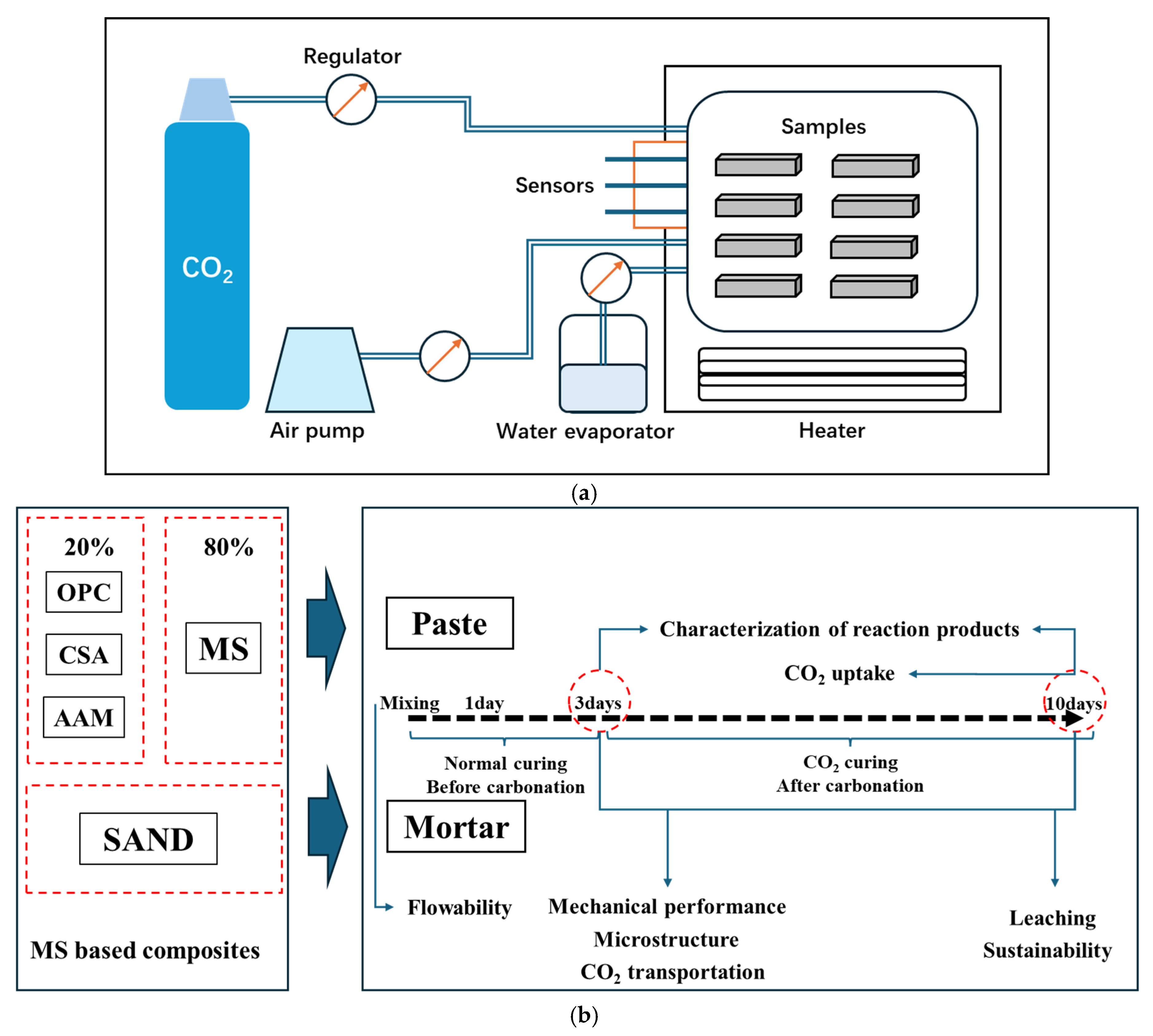
The mix design of MS-blended mortars is shown in Table 2. The binder consisted of 20% of hydraulic materials (OPC, CSA, GBS) and 80% of MS powder. The water-to-binder ratio was set as 0.5. Then, 4M NaOH was applied as an activator in GBS–MS composites to achieve a desirable strength after demolding according to the previous studies [24]. For mortar sample preparation, the standard sand to binder (OPC/CSA/GBS+MS) was 3. Paste samples were prepared to investigate the reaction products before and after carbonation curing, while the mortar samples were prepared for strength and microstructure test. Pastes before and after carbonation curing were named OPC/CAS/AAM-B and OPC/CAS/AAM-A, respectively. Mortars before and after carbonation were coded as OPC/CAS/AAM-BM and OPC/CAS/AAM-AM, respectively. Mortar samples with sizes of 40 mm × 40 mm × 40 mm were prepared and demolded after 1 day of normal curing. Afterward, the demolded samples were placed in a standard concrete curing chamber and cured at 25 °C, RH 98% for 2 days. Then, all samples were moved to a carbonation chamber (as shown in Figure 2) for 7 days of carbonation curing (25 °C, RH 65%, and CO2 dosage of 20%).

2.2.2. Characterization of Reaction Products

  • Mineral phases identification: To investigate the mineral phase development of MS composites before and after carbonation, crushed paste samples after 3 days’ standard curing and 7 days’ carbonation curing were tested with Bruker D8 ADVANCE (Cu tube); the scanning range was from 5° to 70°, the scanning speed was set as 0.2 s/step, and the voltage and current during scanning were 40 KV and 40 A, respectively. The mineral phases were identified using Highscore Plus 3.0.
  • Thermal gravimetric test: To evaluate the bound water and calcium carbonate formation in the paste samples after 3 days’ standard curing and 7 days’ carbonation curing, the powdered paste samples were tested using STA 449 F1. The test temperature range was from ambient temperature to 1000 °C, and the heating rate was 10 °C/min. Nitrogen was applied as the carrier gas during the test.

2.2.3. Microstructure Identification

  • Pore structure of mortars: To evaluate the pore size distribution of mortars after 3 days’ standard curing and 7 days’ carbonation curing, crushed mortar fractions with size of 2–8 mm were prepared and tested using MicroActive AutoPore V 9600 (Micromertics).
  • Morphology of reaction products: To identify the morphology of reaction products in mortars before and after carbonation, crushed MS-blended mortars with AAM, CSA, and OPC were prepared. The morphology images of reaction products were collected using a scanning electron microscope (Regulus 8100, HITACHI).

2.2.4. Evaluation of Mortar Performance

  • Compressive strength test: To evaluate the strength performance evolution of mortars during standard curing and carbonation curing, the compressions of MS-blended mortar cubes were tested using a strength test bench. The cube samples (40 mm × 40 mm × 40 mm) were prepared for compressive strength test according to GB/T 17671-2021 [25]. The average result was collected by testing 6 parts. Mortars after 1 day and 3 days of standard curing and 1, 3, 5, and 7 days of carbonation curing were tested and recorded.
  • Mini-slump flow test: The slump-flow of ternary mortars was conducted using the flow table test, according to GB/T 2419-2005 [26]. An average value of two tested diameters was recorded using a standard conical ring.

2.2.5. Development of Carbonation Front

To identify the carbonation development of mortars during carbonation curing, the mortar samples were split into 2 parts, and then the 0.5 % of phenolphthalein solution was sprayed on the fresh fracture surface according to the description of JGJ/T 23-2011 [27]. Since the carbonation can reduce the alkalinity of concrete, there will be no color change in the carbonated area, while the pink color will be observed in the uncarbonated part.

2.2.6. Evaluation of Sustainability

  • Sustainability coefficient: The sustainability coefficient (SC) of mortars after carbonation curing was evaluated using the calculation according to [28]. The CO2 emissions per kilogram of OPC, CSA, GBS, sand, and water are 0.85 kg, 0.54 kg, 0.035 kg, 0.004 kg, and 0.0006 kg, respectively [29]. The CO2 emission of MS was calculated as natural limestone; the value was selected as 0.0245 kg.

2.2.7. Leaching Properties

  • One batch leaching test: Mortars after 3 days of standard curing and 7 days of carbonation curing were crushed into fractions (<4 mm) for a dynamic leaching process. The distilled water was mixed with mortar fractions with a mass ratio of 10:1, the leaching duration was 24 h, and the shaking frequency was 250 rpm (EN 12457-2) [30]. After the leaching, the leachates were collected using the filter (0.45 μm). Afterward, the filtrates were acidified and tested using ICP-OES.

3. Results

3.1. The Fresh Behavior and Mechanical Performance Evolution of MS-Blended Mortars with Various Hydraulic Materials

3.1.1. Flowability of MS-Blended Mortars with OPC, CSA, and AAM

The flowability of mortars could be effectively influenced by the proportion and the sources of the ingredients, as well as by the pore structures [31,32]. The flowability of various MS composites is shown in Figure 3. MS-blended mortar with 20% of OPC (OPC-M) reached a flowability of 16.5 cm, while AAM-M showed a flow diameter of 15.3 cm. CSA-M presented the poorest flowability among all mortars, reaching only 12.2 cm. In comparison with the flowability of normal standard cement mortar (around 18 cm), the application of a high volume of MS reduced the flow ability of mortars. Furthermore, the introduction of CSA and AAM resulted in a further deterioration in the flowability of mortar composites, which agrees with a previous study of the fresh behaviors of normal CSA and AAM composites [32,33].

3.1.2. Mechanical Performance of MS-Blended Mortars with OPC, CSA, and AAM After Carbonation Curing

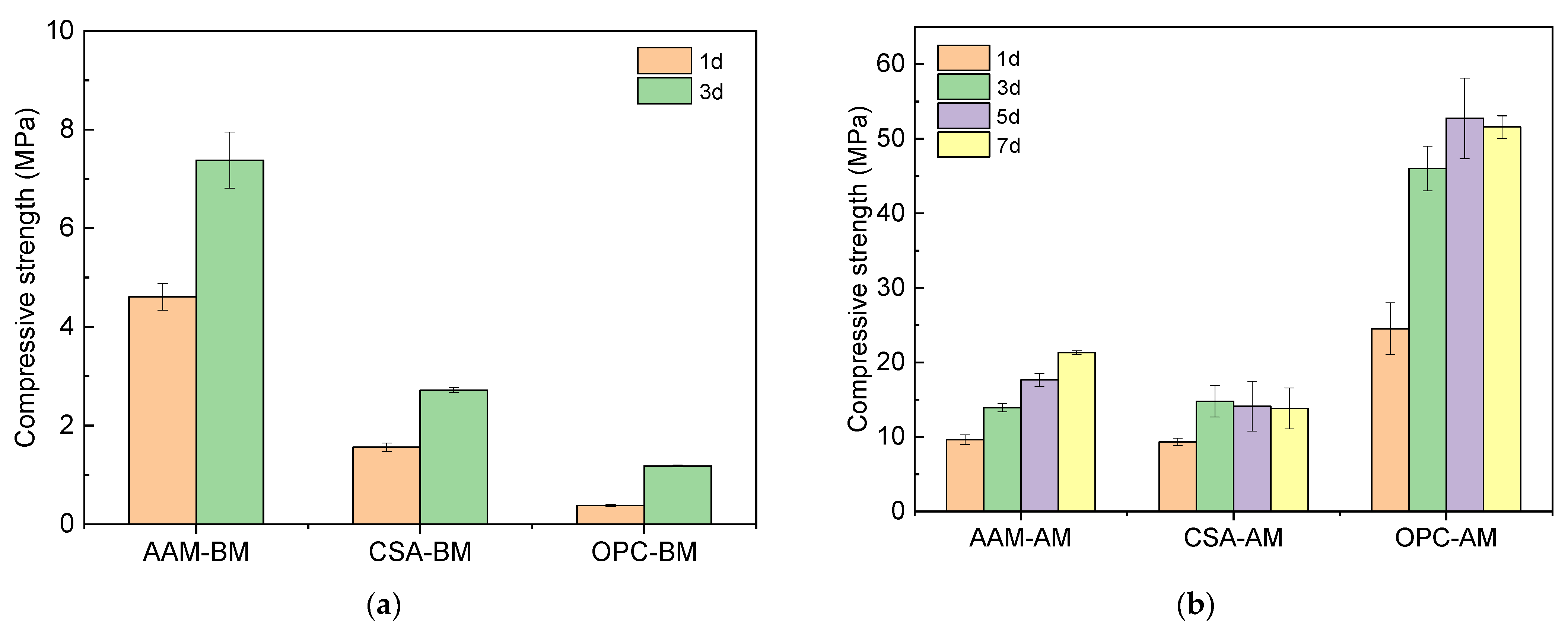
The strength performance results of MS-blended mortars before carbonation are shown in Figure 4a. The compressive strength of AAM-M after 1 day achieved 4.61 MPa and reached 7.38 MPa after 3 days, while the compressive strength of CSA-M mortars after 1 day was 1.56 MPa and increased to 2.72 MPa after 3 days. Meanwhile, OPC-M after 1 day and 3 days had much lower compressive strength than the composites with AAM and CSA, which only reached 0.38 MPa and 1.18 MPa. These results indicate that AAM was feasible for the formation of initial mechanical strength after the standard (normal) curing. This was attributed to the fast reaction of alkali-activated GBS systems at early ages. Meanwhile, the hydration process of CSA cement is usually faster than normal OPC under the same conditions, which has a much higher strength at a very early age [34,35].
During the carbonation curing, the mechanical performance was further enhanced (as shown in Figure 4b). The compressive strength of the samples with the OPC/CSA/AAM shows an increase with the extension of the carbonation curing time. The compressive strength of MS-blended mortar with AAM gradually increased from 9.62 MPa after 1 day to 21.28 MPa after 7 days. The CSA-blended MS mortar reached 9.3 MPa after carbonation for 1 day; afterward, no significant increase in compressive strength was observed. At the same time, the compressive strength of the OPC-blended samples increased from 24.51 MPa to 51.58 MPa during the carbonation curing period. It is clear to see the MS-OPC mortar exhibited the fastest strength growth, while the MS-CSA sample presented the slowest strength development.

3.1.3. Pore Structure Evolution of MS Mortars with OPC, CSA, and AAM After Carbonation Curing

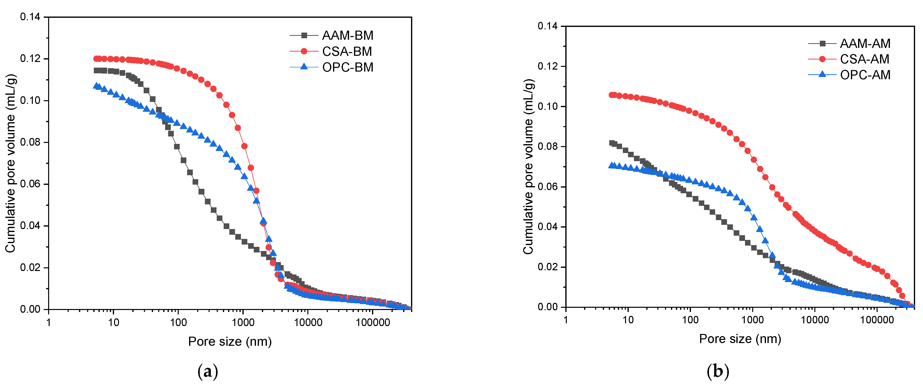
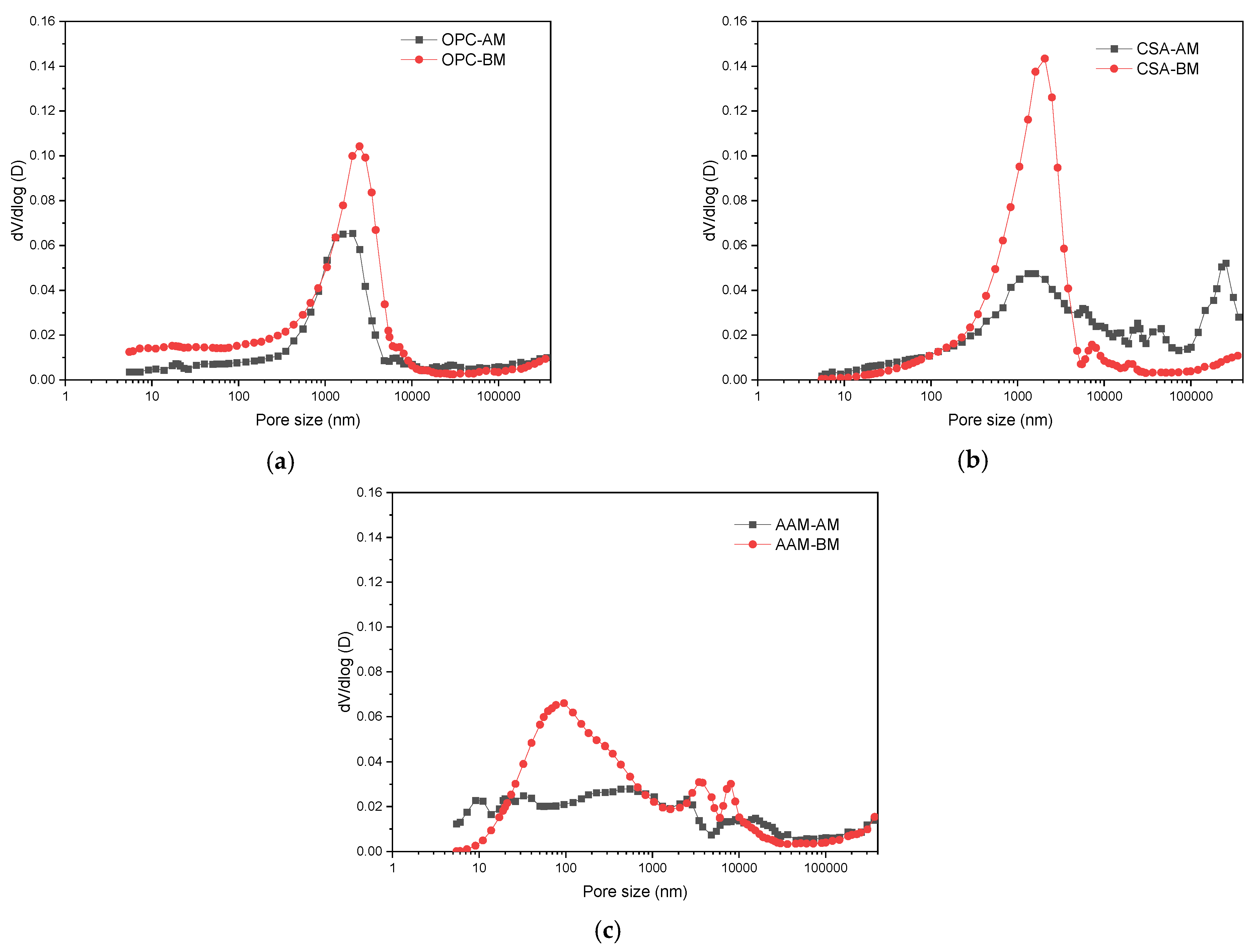
The cumulative pore volume results of MS-blended mortars with OPC, CSA, and AAM before and after carbonation are shown in Figure 5. After carbonation, CSA-BM showed the highest cumulative pore volume of 0.1201 mL/g, while OPC-BM and AAM-BM presented a cumulative pore volume of 0.1068 mL/g and 0.1145 mL/g, respectively. This disagrees with the compressive strength results before carbonation (Section 3.1.2). In previous studies, the properties of the pore distribution were also key factors in the mechanical performance of composites [36,37]. The critical pore size in CSA-BM was around 1000 nm, while it was about 2000 nm in OPC-BM. The introduction of AAM as a hydraulic material strongly suppresses the formation of pores around 1000 nm, and the critical pore size was reduced to around 100 nm (Figure 6). This could be the main reason why AAM-BM exhibited the highest compressive strength. After carbonation curing, it is noticed that the cumulative pore volume decreased significantly compared to the samples after standard curing (Figure 5b). The total pore volume of CSA-AM was decreased to 0.1058 mL/g, which decreased by 12%. OPC-AM and AAM-AM exhibited a reduction of 34% and 28% in the total pore volume of mortar, respectively.
The pore size distributions of MS-blended mortars before and after carbonation are shown in Figure 6. For the MS-blended mortar with OPC, the carbonation curing contributed to the densification of pores of 100–1000 nm, and the critical pore size was reduced from 2.5 um to 1.6 um. Similar densification was also observed in the CSA-blended MS composites. In contrast, the critical pore size of AAM-BM was around 100 nm, and the carbonation reduced the critical pore size to 20 nm. This is in agreement with a previous study of the carbonation of OPC-steel slag composites [16]. In many previous studies, carbonation curing can effectively reduce the pore volume and change the pore distribution of calcium silicate-based composites due to the precipitation of carbonation products [7,14]. The size range of the densified pore was controlled by different hydraulic materials.

3.2. The Carbonation Coefficient of CO2-Cured MS-Blended Mortars

3.2.1. The CO2 Uptake Ability of MS-Blended Binder with OPC, CSA, and AAM

The CO2 uptake ability of MS with various hydraulic materials (AAM, OPC, and CSA) was evaluated, and the results are shown in Figure 7. All samples exhibited a limited CO2 uptake after standard curing due to the natural carbonation during sample preparation. To have an accurate CO2 uptake ability of composites after carbonation, the difference of CO2 uptake of composites between standard curing and carbonation curing was recorded as the real CO2 sequestration ability during the carbonation curing. It is clear to see the categories of hydraulic materials could influence the CO2 uptake ability of MS binders. The sample with AAM binder exhibited a CO2 uptake ability of 9.41%, while MS with CSA and OPC binders showed a CO2 uptake ability of 10.85% and 13.82%, respectively. The application of OPC contributed to the highest CO2 uptake ability of the MS-blended sample. This could be induced by the difference in the available reactive calcium from the hydration products and raw materials.

3.2.2. Carbonation Front Development in MS-Blended Mortars with OPC, CSA, and AAM

The carbonation front development of the AAM-/CSA-/OPC-MS mortars is illustrated in Figure 8. It can be seen that the uncarbonated area in the MS-blended AAM mortar still can be observed after 7 days’ carbonation curing. For the MS-blended mortars with OPC and CSA, the carbonation front developed quit fast. The uncarbonated area was merely observed only after carbonation for 1 day in the mortar with CSA, while full carbonation was achieved in mortars with OPC after 3 days of carbonation curing. This indicates that the CO2 transportation and reaction in the MS-blended mortars were significantly regulated by the types of hydraulic materials. The application of AAM in MS-blended mortars enhanced the resistance to CO2 penetration compared to OPC and CSA. Consequently, compressive strength development could be inhibited due to the poor carbonation degree of mortars.

3.3. The Reaction Products of MS-Based Composites Before and After Carbonation

3.3.1. Mineral Phases Identification of Reaction Products

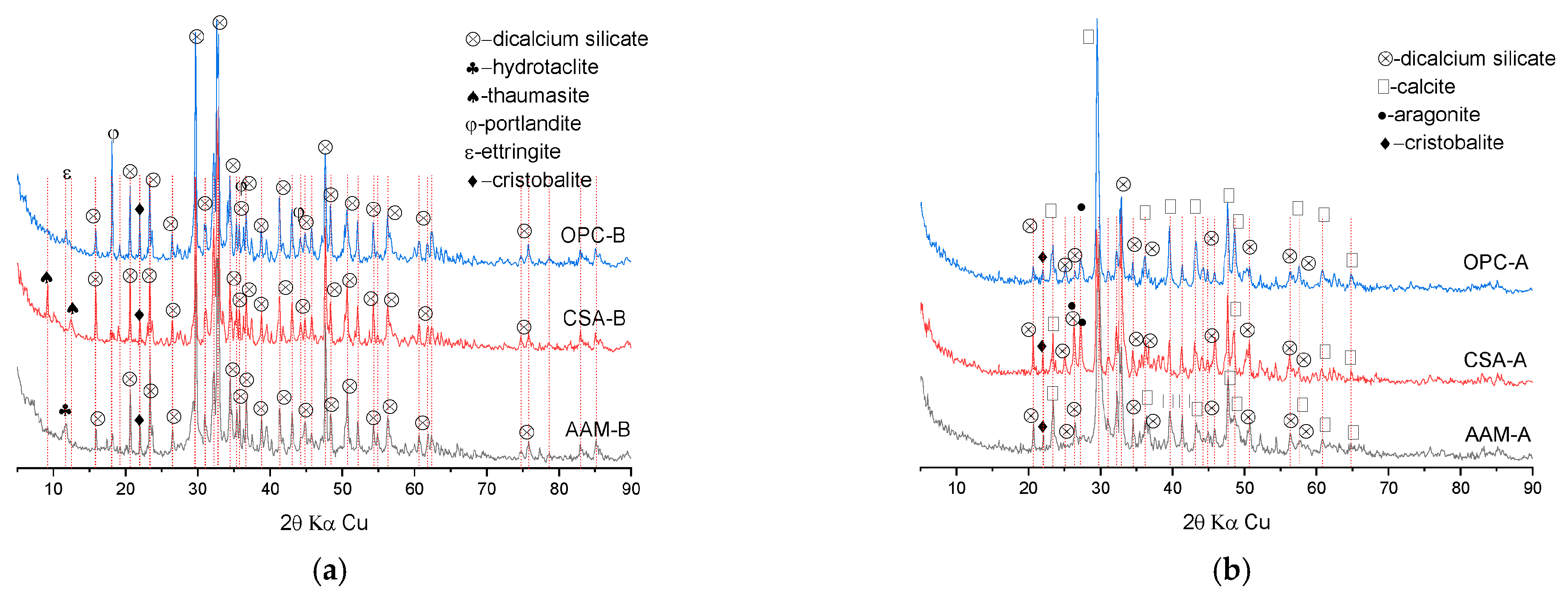
The mineral identification results of MS blends with OPC, CSA, and AAM before and after carbonation curing are shown in Figure 9. For OPC-based composites, the ettringite and calcium hydroxide were the main observed hydration products after 3 days of hydration, which were derived from the clinker hydration including alite, belite, and calcium aluminate [38]. Thaumasite and ettringite were observed in CSA-based MS composites, which are related to the typical reaction products of calcium sulfoaluminate cement [39]. In the AAM-based MS composite, hydrotalcite was identified due to the alkali activation of GBS. In all mixtures, dicalcium silicate was still observed after standard curing due to its low hydraulic reactivity [40]. After carbonation curing for 7 days, calcite and aragonite were formed as the main carbonation reaction products in the OPC- and CSA-based MS composites; besides, hydration products of OPC and CSA were merely observed due to the consumption by the carbonation reaction [41,42].

3.3.2. Thermal Gravimetric Analysis of Reaction Products

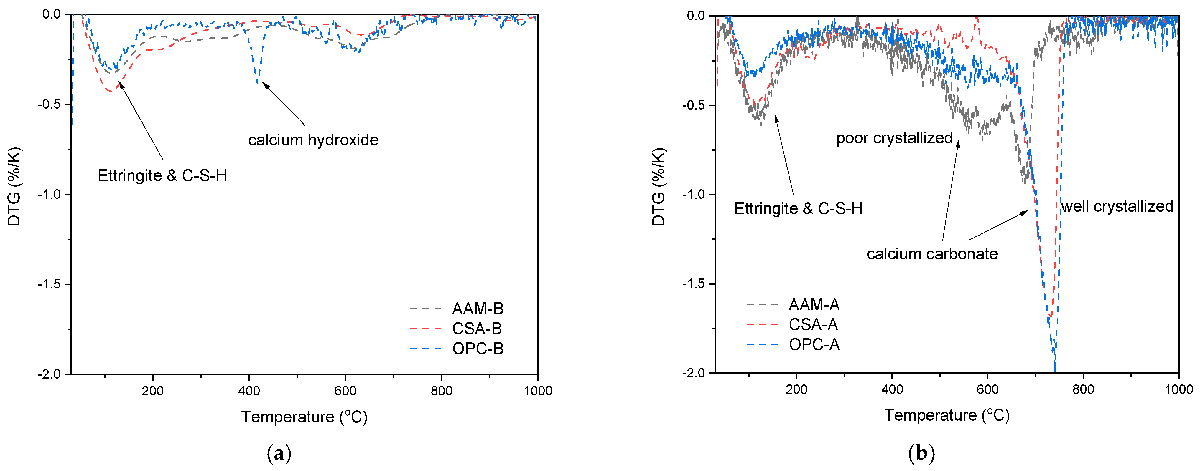
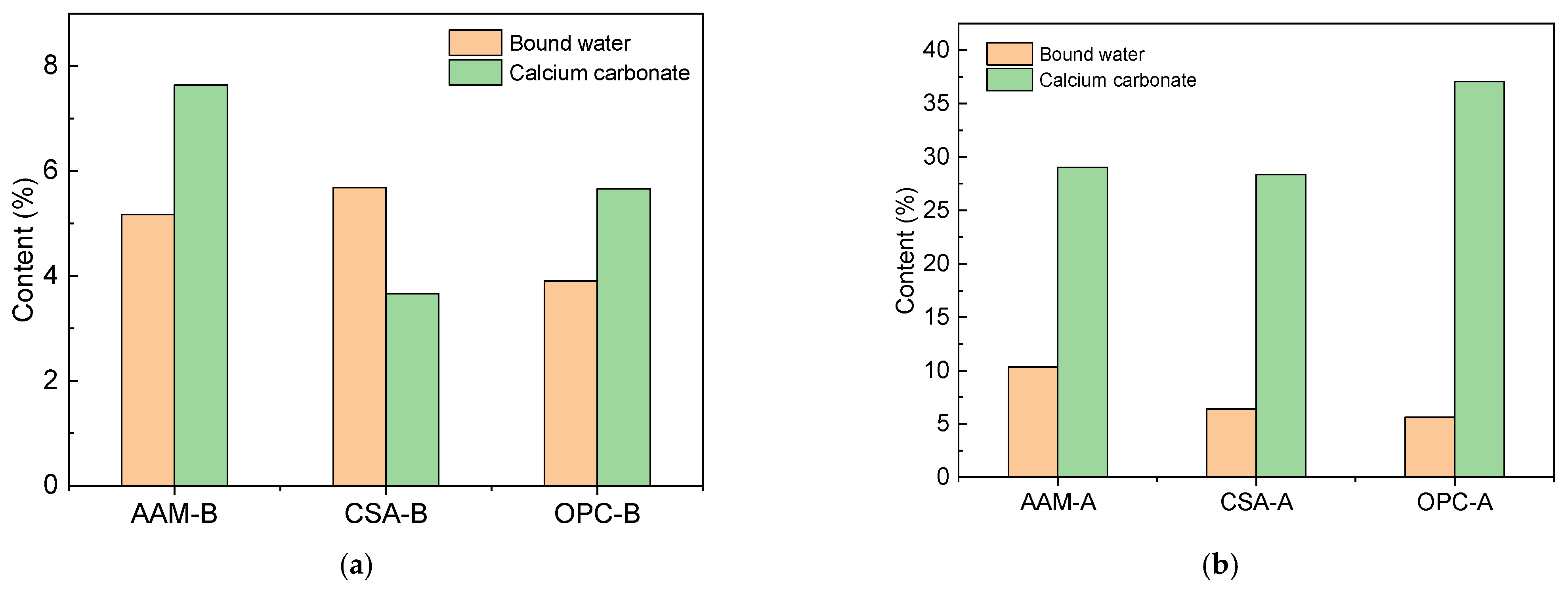
To further understand the reaction products of various mixtures, the TG analysis was conducted, and the results are shown in Figure 10. The poor crystallized calcium carbonate was only observed in the AAM-based MS composite after carbonation curing, which cannot be identified in the XRD analysis. This could be induced by the large amount of Na in the pore solution from the activator of AAM binders, which could inhibit the crystallization process of calcium carbonate. A similar observation also was confirmed in a previous study [43]. The bound water content and calcium carbonate content can be calculated based on the mass loss of the different specimens within the corresponding temperature ranges (as shown in Figure 11). The bound water content in the AAM-/CSA-/OPC-magnesium slag mortar before carbonation was 5.17%, 5.68%, and 3.66%, respectively, while the calcium carbonate content in the AAM-/CSA-/OPC-magnesium slag mortar was 7.64%, 3.66%, and 5.66%, respectively. After carbonation curing, the bound water content of the AAM-/CSA-/OPC-magnesium slag mortar was 10.33%, 6.4%, and 5.62%, respectively, while the calcium carbonate content of the AAM-/CSA-/OPC-magnesium slag mortar were 29.02%, 28.34%, and 37.07%, respectively. Notably, after carbonation, the bond water content had a significant increase only in the AAM-based MS composite rather than in the CSA- and OPC-based MS samples, while the calcium carbonation content showed a large increase among these three, with the largest increase in the OPC-MS mortar. Thus, the increased calcium carbonate and hydrates contributed to the strength development of the corresponding mortars.

3.3.3. Morphology of Reaction Products

The morphology of the reaction products in the MS-blended mortars with AAM, CSA, and OPC are shown in Figure 12. As can be seen, the crossed-layers structure in AAM-B usually indicates the presence of hydrotalcite after the alkali activation of GBS for 3 days, which was in agreement with the XRD results [44]. After carbonation, the pore volume between the crossed layers was filled with carbonation products, and a dense structure can be observed. The incorporation of CSA in the MS blends resulted in amounts of rod-like and sheet structures after standard curing, which was related to the formation of ettringite and the CAH from the hydration of calcium sulfoaluminate cement [45]. The needle-like products and the refinement of pores were observed after carbonation curing. This can be induced by the aragonite and the calcite in CSA blends after carbonation as shown in Figure 9. For the OPC-blended MS samples, the rod-like structure and prismatic-like structure indicated the presence of ettringite and calcium hydroxide from cement clinker hydration. The cubic shape of the reaction product can be identified after carbonation due to the presence of large amounts of calcite.

3.4. The Sustainability of MS-Based Composites

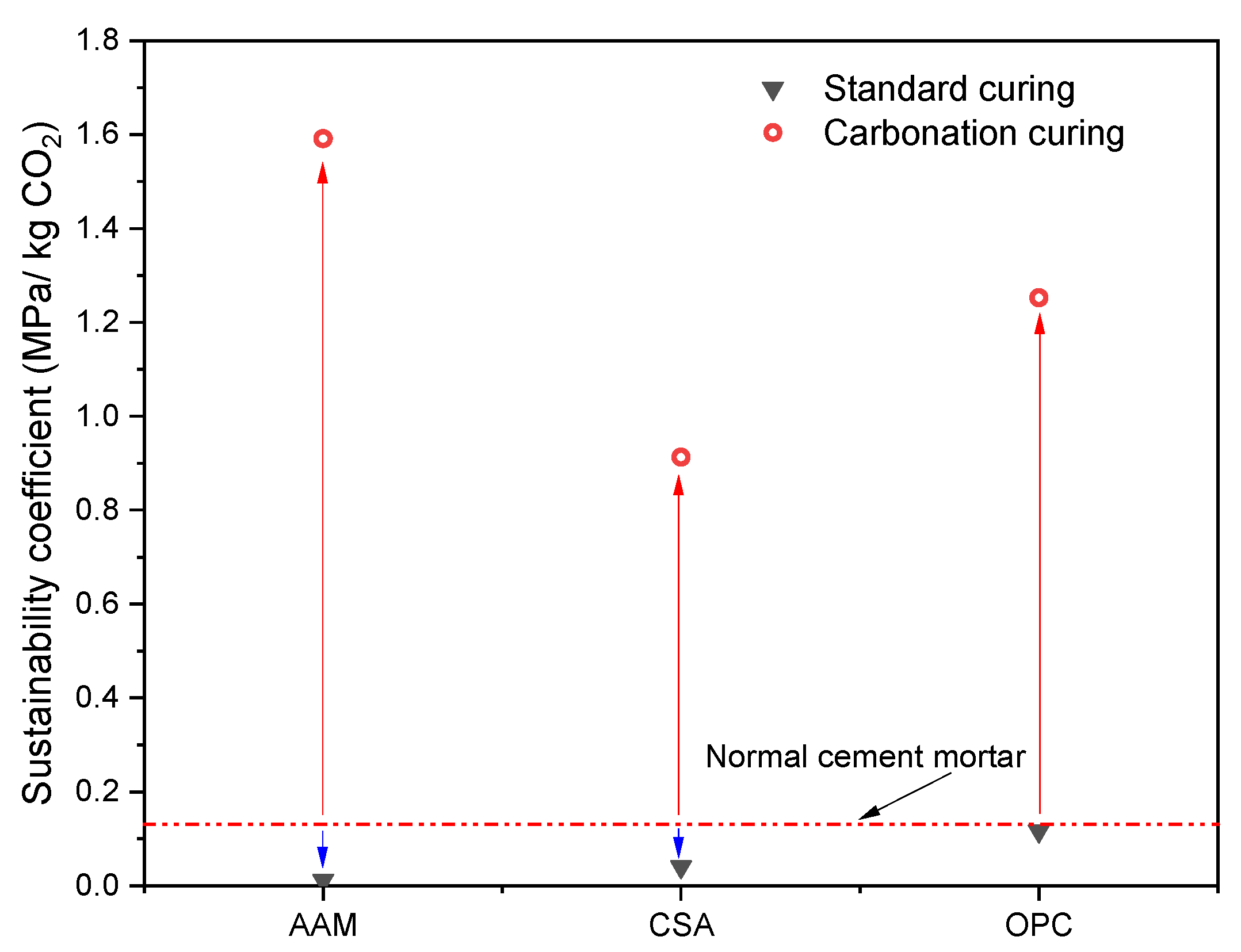
The sustainability coefficient (SC) of carbonated MS-blended mortars with AAM, CSA, and OPC was calculated according to the analysis of TGA, and the results are shown in Figure 13. The red dotted line indicates the SC of cured normal cement mortars produced with pure OPC after 28 days, which is around 0.13 MPa/kg of CO2. The MS-blended mortars subjected to standard curing presented a lower SC compared to the normal cement mortars due to low strength performance after 3 days of hydration. After carbonation curing, the SC was enhanced significantly for all MS-blended mortars. In addition, 1.6 MPa/kg of CO2 was reached by the MS mortars with AAM, while OPC-based sample exhibited an SC of 1.25 MPa/kg of CO2. CSA-based MS mortars presented the lowest SC value of 0.91 MPa/kg of CO2 among all samples. It is clear to see that carbonation curing effectively improved the SC of MS-blended mortars. In addition, the selection of hydraulic materials strongly influenced the SC value of the blended mortars. In comparison with the OPC-based samples, the AAM-based MS-blended mortars produced less CO2 emissions due to the absence of cement clinker, even though medium strength performance was achieved. CSA-based MS mortars exhibited the lowest SC value, which was due to the lowest strength performance of related mortar.

3.5. Leaching of Hazardous Elements

The carbonation reaction of calcium silicate composites usually results in the reduction of alkalinity [21]. Consequently, some hazardous elements could be easily leached out; for example, carbonated steel slag released an amount of V due to the reaction of larnite [46]. To evaluate the environmental impact of MS-blended mortar with OPC, CSA, and AAM as binding materials after carbonation, the concentration of hazardous elements was tested, and the results are shown in Figure 14. The concentration of Cd and Mn in leachates is quite low compared to the limit requirement of the National Class I of solid waste. The leaching of Cu, Ni, and Pb presented a higher dosage among all elements; however, their concentrations still satisfied the requirement of the national standard. For Hg leaching, the concentration of it is slightly higher than the requirement. A previous study indicated highly leachable Hg in MS, which could be derived from the ores for magnesium production [21]. In addition, the reduction in the alkalinity of the composites after carbonation may also promote the increase of leachable Hg [47]. This leaching problem could be controlled by further regulation of the carbonation degree in practical applications. Overall, the MS-blended mortar with AAM as the binding material exhibited lower Cr, Cu, and Pb leaching compared to the OPC- and CSA-based mortars. This could be induced by the slow carbonation of AAM-based MS-blended mortar, which resulted in a low carbonation degree of samples. On the other hand, the pore solution of AAM binders usually exhibits higher alkalinity compared to normal cement samples, which also contributes to the reduction in leaching of Cr, Cu, and Pb [48].

4. Discussion

The combination of hydration and carbonation curing provides a possibility for producing calcium silicates-based building materials as normal OPC composites [16,17]. In this study, the hydraulic materials showed influences on the evolution of the microstructure, strength, and CO2 transportation of MS-based mortars, as well as the curing efficiency under ambient conditions. In general, the reaction of the MS-blended samples can be described as the schematic reaction process in Figure 15. As is well known, the mechanical performance of cementitious materials is mostly determined by physical properties, such as the pore structure [49,50]. In MS-based composites, the pore volume and structural properties after hydration and carbonation were controlled by the initial packing, precipitation of hydration products, and generation of carbonation products.
During hydration curing, in comparison with OPC, CSA and AAM presented a faster hydration reaction [51,52]. This agrees with the results that the bound water in the CSA- and AAM-blended MS composites was higher than that in the OPC sample. Ettringite from the reaction of CSA cement showed a quite low density around 1.77 g/cm3 compared to the C-S-H and CH in hydrated OPC; the rod-like morphology of it contributed to the fast compressive strength of CSA binders after hydration [53]. However, the poor flowability of the MS-CSA binder resulted in poor compacting of the mortar, which resulted in more large pores than MS-AAM after normal curing (Section 3.1.3). This explains the differences in the mechanical performance of MS mortars after normal curing.
During carbonation curing, the CO2 transportation in voids and the carbonation reaction of MS determined the precipitation process of calcium carbonate in the composites, as well as the strength development. For CSA-blended MS mortar, the large pores after normal curing provided desirable diffusion channels for CO2 gas. Since the hydration process of CSA consumed a large amount of free water (in Section 3.3.2), more unsaturated pores could be formed and provided space for CO2 intrusion and reaction. This is also confirmed in previous studies which showed that the large pores and optimized water–solid ratio can promote the CO2 transportation and reaction in composites [7,41]. Thus, the CSA-blended mortars achieved full carbonation after only 1 day. However, the existence of initially large pores was still adverse to the mechanical performance of mortars. Furthermore, the partial decomposition of ettringite under carbonation also resulted in the deterioration of compressive strength [54]. Therefore, the compressive strength of CSA-blended MS mortars showed a limited improvement compared to other samples.
For AAM-MS and OPC-MS systems, the development of the carbonation front (Section 3.2) revealed that the carbonation process in OPC-MS was faster than in AAM-MS composites. Poorly crystallized calcium carbonate and a smaller amount of calcium carbonate compared to OPC blends were identified in AAM-MS (Section 3.3.2). This indicates that the carbonation reaction of MS was suppressed in AAM systems. This could be caused by the chemical differences in pore solution of mortars between the OPC and AAM blends. In previous cases, the Na concentration was shown to be the key factor to control the resistance to carbonation for alkali-activated slag [55]. Firstly, the presence of Na promoted the stability of amorphous and poorly crystallized calcium carbonate by changing the nucleation mechanisms [56]. This agreed with the presence of low-crystallized calcium carbonate in the AAM system, as shown in Figure 16, where the decomposition of calcium carbonate was presented at a lower temperature compared to OPC-MS and CSA-MS. SEM also indicated that AAM-MS exhibited a smaller size of calcium carbonate after carbonation. Consequently, a stronger densification was observed in the MIP results, which showed a high volume of gel pores in the AAM systems after carbonation (Section 3.1.3). Furthermore, the Na in the pore solution was also proved to play the role of pH buffer during carbonation [56,57]. Additionally, a large number of fine pores in the AAM-blended MS mortars was not favorable to the evaporation of free water and the formation of unsaturated channels for CO2 transportation [58]. Therefore, the CO2 transportation in AAM-MS was significantly slowed down compared to the OPC systems. This also explains the slow strength development of the AAM-blended MS mortars during ambient carbonation curing. In practical production, these differences should be considered for an optimal setting and design of carbonation curing conditions.

5. Conclusions

This study investigates the role of hydraulic materials, including alkali-activated material, calcium sulfoaluminate cement, and ordinary Portland cement on the performance evolution of MS-blended binders after hydration and carbonation. Properties evaluation consisting of fresh behavior, mechanical performance, microstructure, and reaction products of the blended binder was performed. The results provide a comprehensive understanding of the binder system design for the production of MS-based building materials by carbonation curing. Some conclusions can be addressed as follows:
(1)
The application of alkali-activated GBS in the preparation of MS mortars resulted in the highest compressive strength of 7.38 MPa compared to CSA (2.72 MPa) and OPC (1.18 MPa) after the hydration stage. After carbonation, the compressive strength of AAM-MS mortar, OPC-MS mortar, and CSA-MS mortar achieved 21.28 MPa, 9.3 MPa, and 51.58 MPa, respectively.
(2)
The duration of full carbonation of blended mortar was 1 day, 3 days, and more than 7 days for CSA-, OPC-, and AAM-blended samples, respectively. The CO2 uptake ability achieved 13.82%, 10.85%, and 9.51% by the OPC-, CSA-, and AAM-blended binders, respectively.
(3)
The application of CSA in MS-blended mortar contributed to the highest porosity and volume of large pores compared to AAM and OPC. In the carbonated CSA-blended binder, well-crystallized calcite and aragonite were identified. Calcite was the only calcium carbonate polymorph in the carbonated OPC-blended binder, while an amount of poorly crystallized calcite existed in AAM-blended sample.
(4)
The leaching of Cd, Cr, Cu, Mn, Ni, and Pb from carbonated MS mortars satisfied the requirement of National Class I solid wastes. The Hg leaching was slightly higher than the requirement (<50 µg/L). AAM-based binders exhibited a higher ability on the leaching inhibition of Cr, Cu, and Pb.
In the practical production process, the performance of building materials is usually optimized by the curing strategies, mix design, and cost effectiveness. This study focused on the influences of hydraulic materials on the performance evolution of MS mortars during ambient hydration and carbonation. However, other factors such as the compacting degree, content of hydraulic materials, and pre-treatment still need to be clearly explained for engineering production, which will be further investigated in the following study.

Author Contributions

Conceptualization, G.L.; methodology, G.L. and B.Y.; software, G.L. and B.Y.; validation, G.L., B.Y., S.L. and J.W.; formal analysis, B.Y.; investigation, G.L., B.Y., S.L. and J.W.; resources, G.L.; data curation, G.L. and B.Y.; writing—original draft preparation, G.L., B.Y., S.L. and J.W.; writing—review and editing, G.L.; visualization, G.L. and B.Y.; supervision, G.L. and J.W.; project administration, G.L.; funding acquisition, G.L. All authors have read and agreed to the published version of the manuscript.

Funding

The financial support of ‘National Natural Science Foundation of China (No. 52208288)’, ‘International Postdoctoral Exchange Fellowship Program (Talent-Introduction Program)’ (YJ20210154), and ‘Young Talent Support Plan’ of Xi’an Jiaotong University are gratefully acknowledged.

Data Availability Statement

The data presented in this study are available on request from the corresponding author.

Conflicts of Interest

The authors declare no conflict of interest.

References

  1. Li, X.; Qin, D.; Hu, Y.; Ahmad, W.; Ahmad, A.; Aslam, F.; Joyklad, P. A Systematic Review of Waste Materials in Cement-Based Composites for Construction Applications. J. Build. Eng. 2022, 45, 103447. [Google Scholar] [CrossRef]
  2. Wu, S.; Shao, Z.; Andrew, R.M.; Bing, L.; Wang, J.; Niu, L.; Liu, Z.; Xi, F. Global CO2 Uptake by Cement Materials Accounts 1930–2023. Sci. Data 2024, 11, 1–11. [Google Scholar] [CrossRef]
  3. Zhong, X.; Hu, M.; Deetman, S.; Steubing, B.; Lin, H.X.; Hernandez, G.A.; Harpprecht, C.; Zhang, C.; Tukker, A.; Behrens, P. Global Greenhouse Gas Emissions from Residential and Commercial Building Materials and Mitigation Strategies to 2060. Nat. Commun. 2021, 12, 6126. [Google Scholar] [CrossRef]
  4. Perez-Cortes, P.; Escalante-Garcia, J.I. Design and Optimization of Alkaline Binders of Limestone-Metakaolin—A Comparison of Strength, Microstructure and Sustainability with Portland Cement and Geopolymers. J. Clean. Prod. 2020, 273, 123118. [Google Scholar] [CrossRef]
  5. Sun, Q.; Tian, S.; Sun, Q.; Li, B.; Cai, C.; Xia, Y.; Wei, X.; Mu, Q. Preparation and Microstructure of Fly Ash Geopolymer Paste Backfill Material. J. Clean. Prod. 2019, 225, 376–390. [Google Scholar] [CrossRef]
  6. Liu, G.; Florea, M.V.A.; Brouwers, H.J.H. Performance Evaluation of Sustainable High Strength Mortars Incorporating High Volume Waste Glass as Binder. Constr. Build. Mater. 2019, 202, 574–588. [Google Scholar] [CrossRef]
  7. Liang, C.; Li, B.; Guo, M.-Z.; Hou, S.; Wang, S.; Gao, Y.; Wang, X. Effects of Early-Age Carbonation Curing on the Properties of Cement-Based Materials: A Review. J. Build. Eng. 2024, 84, 108495. [Google Scholar] [CrossRef]
  8. Kashef-Haghighi, S.; Shao, Y.; Ghoshal, S. Mathematical Modeling of CO2 Uptake by Concrete during Accelerated Carbonation Curing. Cem. Concr. Res. 2015, 67, 1–10. [Google Scholar] [CrossRef]
  9. Liu, Z.; Meng, W. Fundamental Understanding of Carbonation Curing and Durability of Carbonation-Cured Cement-Based Composites: A Review. J. CO2 Util. 2021, 44, 101428. [Google Scholar] [CrossRef]
  10. Mechanisms of Carbonation Hydration Hardening in Portland Cements—ScienceDirect. Available online: https://www.sciencedirect.com/science/article/pii/S0008884621003367 (accessed on 29 October 2024).
  11. Bagchi, A.K. Historical Perspectives on Development. Int. Handb. Dev. Econ. 2008, 1, 16–31. [Google Scholar]
  12. Jin, Y.; Xiong, Z.; Feng, W.; Zheng, D.; Ng, S.; Wang, Y. Semi-Dry Carbonated Recycled Concrete Paste as Alternative to Limestone and Its Reactivity in LC3. J. Therm. Anal. Calorim. 2024, 149, 215–7224. [Google Scholar] [CrossRef]
  13. Poon, C.S.; Shen, P.; Jiang, Y.; Ma, Z.; Xuan, D. Total Recycling of Concrete Waste Using Accelerated Carbonation: A Review. Cem. Concr. Res. 2023, 173, 107284. [Google Scholar] [CrossRef]
  14. Mo, L.; Zhang, F.; Deng, M.; Jin, F.; Al-Tabbaa, A.; Wang, A. Accelerated Carbonation and Performance of Concrete Made with Steel Slag as Binding Materials and Aggregates. Cem. Concr. Compos. 2017, 83, 138–145. [Google Scholar] [CrossRef]
  15. Liu, P.; Mo, L.; Zhang, Z. Effects of Carbonation Degree on the Hydration Reactivity of Steel Slag in Cement-Based Materials. Constr. Build. Mater. 2023, 370, 130653. [Google Scholar] [CrossRef]
  16. Liu, G.; Schollbach, K.; van der Laan, S.; Tang, P.; Florea, M.V.A.; Brouwers, H.J.H. Recycling and Utilization of High Volume Converter Steel Slag into CO2 Activated Mortars—The Role of Slag Particle Size. Resour. Conserv. Recycl. 2020, 160, 104883. [Google Scholar] [CrossRef]
  17. Liu, G.; Rong, H.; Wang, J. Valorization of Converter Steel Slag in Sustainable Mortars by a Combined Alkali and Carbonation Activation. J. Clean. Prod. 2022, 370, 133519. [Google Scholar] [CrossRef]
  18. Wang, Y.; Liu, J.; Hu, X. Utilization of Accelerated Carbonation to Enhance the Application of Steel Slag: A Review. J. Sustain. Cem.-Based Mater. 2023, 12, 471–486. [Google Scholar] [CrossRef]
  19. Song, Q.; Guo, M.-Z.; Wang, L.; Ling, T.-C. Use of Steel Slag as Sustainable Construction Materials: A Review of Accelerated Carbonation Treatment. Resour. Conserv. Recycl. 2021, 173, 105740. [Google Scholar] [CrossRef]
  20. Yang, X.; Dong, F.; Zhang, X.; Li, C.; Gao, Q. Review on Comprehensive Utilization of Magnesium Slag and Development Prospect of Preparing Backfilling Materials. Minerals 2022, 12, 1415. [Google Scholar] [CrossRef]
  21. Wang, X.; Yan, X.; Li, X. Environmental Risks for Application of Magnesium Slag to Soils in China. J. Integr. Agric. 2020, 19, 1671–1679. [Google Scholar] [CrossRef]
  22. Amini, O.; Ghasemi, M. Laboratory Study of the Effects of Using Magnesium Slag on the Geotechnical Properties of Cement Stabilized Soil. Constr. Build. Mater. 2019, 223, 409–420. [Google Scholar] [CrossRef]
  23. GB 8076-2008; National Standard for Concrete Admixtures. Standards Press of China (SPC): Beijing, China, 2008.
  24. Sasui, S.; Kim, G.; Nam, J.; van Riessen, A.; Eu, H.; Chansomsak, S.; Alam, S.F.; Cho, C.H. Incorporation of Waste Glass as an Activator in Class-C Fly Ash/GGBS Based Alkali Activated Material. Materials 2020, 13, 3906. [Google Scholar] [CrossRef]
  25. GB/T 17671-2021; Test Method of Cement Mortar Strength. Standards Press of China (SPC): Beijing, China, 2021.
  26. GB/T 2419-2005; Test Method for Fluidity of Cement Mortar. Standards Press of China (SPC): Beijing, China, 2005.
  27. JGJT23-2011; Technical Specification for Inspection of Concrete Compressive Strength by Rebound Method. Standards Press of China (SPC): Beijing, China, 2011.
  28. Damineli, B.L.; Kemeid, F.M.; Aguiar, P.S.; John, V.M. Measuring the Eco-Efficiency of Cement Use. Cem. Concr. Compos. 2010, 32, 555–562. [Google Scholar] [CrossRef]
  29. Pillai, R.G.; Gettu, R.; Santhanam, M.; Rengaraju, S.; Dhandapani, Y.; Rathnarajan, S.; Basavaraj, A.S. Service Life and Life Cycle Assessment of Reinforced Concrete Systems with Limestone Calcined Clay Cement (LC3). Cem. Concr. Res. 2019, 118, 111–119. [Google Scholar] [CrossRef]
  30. EN 12457-2:2002; Characterisation of Waste—Leaching, 2022nd ed. CEN: Milan, Italy, 2004.
  31. Cortes, D.; Kim, H.-K.; Palomino, A.; Santamarina, J. Rheological and Mechanical Properties of Mortars Prepared with Natural and Manufactured Sands. Cem. Concr. Res. 2008, 38, 1142–1147. [Google Scholar] [CrossRef]
  32. Yahia, A.; Tanimura, M.; Shimoyama, Y. Rheological Properties of Highly Flowable Mortar Containing Limestone Filler-Effect of Powder Content and W/C Ratio. Cem. Concr. Res. 2005, 35, 532–539. [Google Scholar] [CrossRef]
  33. Mohan, M.K.; Rahul, A.V.; De Schutter, G.; Van Tittelboom, K. Early Age Hydration, Rheology and Pumping Characteristics of CSA Cement-Based 3D Printable Concrete. Constr. Build. Mater. 2021, 275, 122136. [Google Scholar] [CrossRef]
  34. Chaunsali, P.; Mondal, P. Physico-Chemical Interaction between Mineral Admixtures and OPC–Calcium Sulfoaluminate (CSA) Cements and Its Influence on Early-Age Expansion. Cem. Concr. Res. 2016, 80, 10–20. [Google Scholar] [CrossRef]
  35. Huang, Y.; Sun, H.; Liu, W.; Zhao, H.; Dong, D.; Zhao, P.; Lu, L. Improved Early-Age and Late-Age Performances of Calcium Sulphoaluminate Cement with the Presence of Calcium Nitrate. Constr. Build. Mater. 2022, 327, 126927. [Google Scholar] [CrossRef]
  36. Xiao, J.; Lv, Z.; Duan, Z.; Zhang, C. Pore Structure Characteristics, Modulation and Its Effect on Concrete Properties: A Review. Constr. Build. Mater. 2023, 397, 132430. [Google Scholar] [CrossRef]
  37. Wang, F.; Sun, C. Effect of Pore Structure on Compressive Strength and Permeability of Planting Recycled Concrete. Constr. Build. Mater. 2023, 394, 132167. [Google Scholar] [CrossRef]
  38. Scrivener, K.; Ouzia, A.; Juilland, P.; Kunhi Mohamed, A. Advances in Understanding Cement Hydration Mechanisms. Cem. Concr. Res. 2019, 124, 105823. [Google Scholar] [CrossRef]
  39. Galan, I.; Steindl, F.; Grengg, C.; Dietzel, M.; Mittermayr, F. On the Hydration of Ternesite and the Formation of Thaumasite. Cem. Concr. Res. 2023, 172, 107212. [Google Scholar] [CrossRef]
  40. Thomas, J.J.; Ghazizadeh, S.; Masoero, E. Kinetic Mechanisms and Activation Energies for Hydration of Standard and Highly Reactive Forms of β-Dicalcium Silicate (C2S). Cem. Concr. Res. 2017, 100, 322–328. [Google Scholar] [CrossRef]
  41. Hargis, C.W.; Lothenbach, B.; Müller, C.J.; Winnefeld, F. Carbonation of Calcium Sulfoaluminate Mortars. Cem. Concr. Compos. 2017, 80, 123–134. [Google Scholar] [CrossRef]
  42. Zajac, M.; Skocek, J.; Durdzinski, P.; Bullerjahn, F.; Skibsted, J.; Ben Haha, M. Effect of Carbonated Cement Paste on Composite Cement Hydration and Performance. Cem. Concr. Res. 2020, 134, 106090. [Google Scholar] [CrossRef]
  43. Liu, G.; Florea, M.; Brouwers, H. The Role of Recycled Waste Glass Incorporation on the Carbonation Behaviour of Sodium Carbonate Activated Slag Mortar. J. Clean. Prod. 2021, 292, 126050. [Google Scholar] [CrossRef]
  44. Kamath, M.; Prashant, S.; Kumar, M. Micro-Characterisation of Alkali Activated Paste with Fly Ash-GGBS-Metakaolin Binder System with Ambient Setting Characteristics. Constr. Build. Mater. 2021, 277, 122323. [Google Scholar] [CrossRef]
  45. Telesca, A.; Marroccoli, M.; Pace, M.L.; Tomasulo, M.; Valenti, G.L.; Monteiro, P.J.M. A Hydration Study of Various Calcium Sulfoaluminate Cements. Cem. Concr. Compos. 2014, 53, 224–232. [Google Scholar] [CrossRef]
  46. Baciocchi, R.; Costa, G.; Polettini, A.; Pomi, R. Effects of Thin-Film Accelerated Carbonation on Steel Slag Leaching. J. Hazard. Mater. 2015, 286, 369–378. [Google Scholar] [CrossRef]
  47. Xu, J.; Kleja, D.B.; Biester, H.; Lagerkvist, A.; Kumpiene, J. Influence of Particle Size Distribution, Organic Carbon, pH and Chlorides on Washing of Mercury Contaminated Soil. Chemosphere 2014, 109, 99–105. [Google Scholar] [CrossRef]
  48. Orhan, G. Leaching and Cementation of Heavy Metals from Electric Arc Furnace Dust in Alkaline Medium. Hydrometallurgy 2005, 78, 236–245. [Google Scholar] [CrossRef]
  49. Zuo, W.; Zhao, X.; Luo, J.; He, Z.; Zhao, J. Investigating the Impact of Carbonation Curing Concentrations on the Mechanical Properties and Microstructure of Recycled Concrete. J. Build. Eng. 2024, 96, 110465. [Google Scholar] [CrossRef]
  50. Shen, P.; Lu, L.; He, Y.; Wang, F.; Hu, S. The Effect of Curing Regimes on the Mechanical Properties, Nano-Mechanical Properties and Microstructure of Ultra-High Performance Concrete. Cem. Concr. Res. 2019, 118, 1–13. [Google Scholar] [CrossRef]
  51. Park, S.; Jeong, Y.; Moon, J.; Lee, N. Hydration Characteristics of Calcium Sulfoaluminate (CSA) Cement/Portland Cement Blended Pastes. J. Build. Eng. 2021, 34, 101880. [Google Scholar] [CrossRef]
  52. Wang, S.-D.; Scrivener, K.L. Hydration Products of Alkali Activated Slag Cement. Cem. Concr. Res. 1995, 25, 561–571. [Google Scholar] [CrossRef]
  53. Tawfik, A.; Mohammed, M.S.; Abd-El-Raoof, F.; Aggor, F.; Ahmed, E.M. Heat-Treated Portland Cement Pastes Incorporating Superabsorbent Hydrogels for Precast Applications. Interceram-Int. Ceram. Rev. 2018, 67, 30–37. [Google Scholar] [CrossRef]
  54. Nishikawa, T.; Suzuki, K.; Ito, S.; Sato, K.; Takebe, T. Decomposition of Synthesized Ettringite by Carbonation. Cem. Concr. Res. 1992, 22, 6–14. [Google Scholar] [CrossRef]
  55. Shi, Z.; Shi, C.; Wan, S.; Li, N.; Zhang, Z. Effect of Alkali Dosage and Silicate Modulus on Carbonation of Alkali-Activated Slag Mortars. Cem. Concr. Res. 2018, 113, 55–64. [Google Scholar] [CrossRef]
  56. Azar, P.; Patapy, C.; Samson, G.; Cussigh, F.; Frouin, L.; Cyr, M. Effect of Natural and Accelerated Carbonation on Microstructure and pH of Sodium Carbonate Alkali-Activated Slag. Cem. Concr. Res. 2024, 181, 107525. [Google Scholar] [CrossRef]
  57. Leemann, A.; Moro, F. Carbonation of Concrete: The Role of CO2 Concentration, Relative Humidity and CO2 Buffer Capacity. Mater. Struct. 2017, 50, 30. [Google Scholar] [CrossRef]
  58. Siddique, S.; Naqi, A.; Jang, J.G. Influence of Water to Cement Ratio on CO2 Uptake Capacity of Belite-Rich Cement upon Exposure to Carbonation Curing. Cem. Concr. Compos. 2020, 111, 103616. [Google Scholar] [CrossRef]
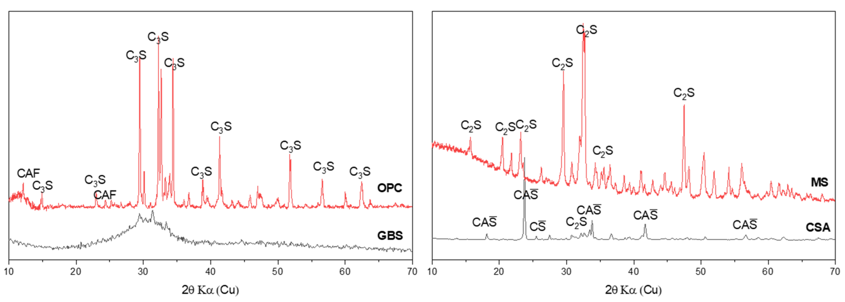
Figure 1. Mineral composition of raw materials (C2S—belite, C3S—alite, CAF—calcium aluminoferrite, CAS—calcium aluminate sulfate).
Buildings 15 03062 g001
Figure 2. Schematic diagram of the carbonation curing system (a) and experiment design (b).
Buildings 15 03062 g002
Figure 3. Mini-slump flow of MS-blended mortars.
Buildings 15 03062 g003
Figure 4. Compressive strength of mortars before (a) and after carbonation (b).
Buildings 15 03062 g004
Figure 5. Cumulative pore volume of mortars before (a) and after carbonation (b).
Buildings 15 03062 g005
Figure 6. Pore size distribution of mixtures before and after carbonation: (a) OPC-MS mortar, (b) CSA-MS mortar, and (c) AAM-MS mortar.
Buildings 15 03062 g006
Figure 7. CO2 uptake in AAM-, CSA-, and OPC-MS binders (7 days).
Buildings 15 03062 g007
Figure 8. Development of carbonation fronts in mortars during the carbonation curing period.
Buildings 15 03062 g008
Figure 9. Reaction products in mixtures (a) before carbonation and (b) after carbonation.
Buildings 15 03062 g009
Figure 10. DTG results of mixtures (a) before carbonation and (b) after carbonation.
Buildings 15 03062 g010
Figure 11. Bound water and calcium carbonate content in mixtures (a) before carbonation and (b) after carbonation.
Buildings 15 03062 g011
Figure 12. SEM images of MS-blended mortars before and after carbonation (20,000×).
Buildings 15 03062 g012
Figure 13. Sustainability coefficient of various MS mortars with AAM, CSA, and OPC after standard and carbonation curing.
Buildings 15 03062 g013
Figure 14. Hazardous elements leaching of carbonated MS-blended mortars.
Buildings 15 03062 g014
Figure 15. The schematic reaction process of MS-based composites at different stages.
Buildings 15 03062 g015
Figure 16. Carbonation front in different MS-based composites.
Buildings 15 03062 g016
Table 1. The main chemical composition of raw materials.
Chemical CompositionOPC (%)MS (%)CSA (%)GBS (%)
Na2O/0.0560.2010.671
MgO1.7123.291.45510.847
Al2O33.7931.2938.63119.312
SiO216.18831.358.17832.526
SO34.0550.0899.2592.500
K2O0.187/0.3660.287
CaO67.96863.4338.28532.365
TiO20.2770.041.4030.781
Cr2O30.01/0.0350.748
MnO0.094/0.0150.314
Fe2O33.5890.381.7530.258
ZnO0.10.004//
Cl0.041/0.067/
Table 2. The mix design of MS composites.
Sample IDOPC (g)CSA (g)GBS (g)MS (g)Water (g)Activator (g)Sand (g)
OPC900036022501350
CSA090036022501350
AAM0090360225361350
Disclaimer/Publisher’s Note: The statements, opinions and data contained in all publications are solely those of the individual author(s) and contributor(s) and not of MDPI and/or the editor(s). MDPI and/or the editor(s) disclaim responsibility for any injury to people or property resulting from any ideas, methods, instructions or products referred to in the content.