Abstract
This paper presents an investigation into the mechanical performance of a subway station prefabricated assembly air duct (PAAD), constructed by assembling the prefabricated reinforced concrete segments. The study is implemented through numerical analysis, focusing on the impact from the grouting defects in the sleeve grouting connection and assembly error defects along the assembly direction. The results demonstrate that the assembly error defect has almost no impact on the mechanical performance of the PAAD, satisfying the safety requirements for use. However, the grouting defects in the sleeve grouting connection can influence the mechanical performance of the PAAD, in which the maximum tensile stress of concrete in the sleeve grouting connection with a 20 mm-long bottom grouting defect is greater than the tensile strength of that concrete, and strengthening treatment is thus required for ensuring the structure’s safety and reliability. This study provides the basis for applying a PAAD in subway station construction.
1. Introduction
Underground engineering has developed widely in recent years, since the acceleration of urbanization processes around the world has caused many problems, such as land resource scarcity and urban traffic congestion [1,2,3]. Compared with cast-in-place technology, prefabricated assembly technology has obvious advantages when employed for constructing urban underground engineering (with the industry upgrading) [4,5], since it can improve resource utilization efficiency, save resources and energy, reduce pollution, protect the environment, and achieve sustainable development [6], regarded as the main development direction of building underground engineering structures [7,8,9]. Especially, the aforementioned prefabricated assembly technology also can ensure the quality of the prefabricated segments, significantly reducing the construction period and the amount of wet work on site, which have been extensively employed in building segments of the subway tunnel [10,11,12].
In the construction of a subway station, the air duct is an important internal structural component for controlling the temperature and smoke in the ventilation system, whereas it is difficult to construct using cast-in-place technology due to the narrow construction space and complex construction processes [13], and thus a prefabricated assembly air duct (PAAD) is worth being applied. In view of the published literature, there is much research on the stress performance of the general prefabricated structural components, such as the influence of height-to-thickness ratio on the stress performance of the sandwich walls [14], the mechanical performance of the laminated composite panels under different interface treatments [15], and the seismic response of the shallow-buried rectangular structures [16]. However, there are few application examples of PAAD in subway stations [17], since the corresponding theory and design methods are relatively lacking [18,19].
The connection joint influences the performance of the prefabricated assembly segments [9], in which the sleeve grouting connection joint is commonly employed for fixing the segments. However, there are adverse factors: bubbles, blockages, and grout leakage easily occur when implementing the grouting process of the sleeve grouting connection joint in practical construction [20], which can induce grouting defects in the connection joint [21,22]. Moreover, an assembly error defect is prone to appear and difficult to eliminate during the manufacturing and assembly process in construction [23], which also affects the strength and mechanical properties of the assembled segment, seriously restricting the development and application of underground assembly structures. Therefore, it is difficult to directly apply the general theories and methods of prefabricated assembly structures for designing PAADs, and there is an urgent requirement of further studying the mechanical performance of PAADs subject to the aforementioned assembly and grouting defects.
This paper presents a case study investigating the mechanical performance of PAADs in a subway station, which is constructed by assembling the prefabricated reinforced concrete (RC) segments. The study is implemented through numerical analysis, focusing on the impact from the grouting defects in the sleeve grouting connection and assembly error defects along the assembly direction, which is expected to provide the basis for applying PAADs in subway station construction.
2. Profile of Prefabricated Assembly Air Ducts in a Subway Station
The prefabricated assembly air duct (PAAD) is newly developed for application in the ventilation system of the subway station. As shown in Figure 1a, the PAAD is a fully prefabricated assembly reinforced concrete (RC) structure in the subway station. In the construction of the PAAD, the RC segment is firstly prefabricated on the ground (step 1) and then transported into the interior of the subway station (step 2), where it is lifted and assembled using a customized lifting vehicle thereafter (step 3), as shown in Figure 1b. Moreover, the interface optimization of the PAAD is carried out after the lifting is completed.
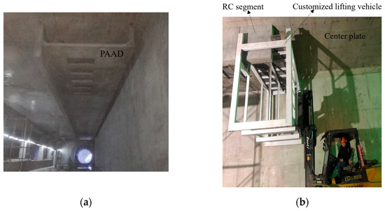
Figure 1.
Overview of PAAD constructed by assembling prefabricated RC segments: (a) PAAD; (b) assembling segment.
The PAAD is assembled with 33 individual prefabricated RC segments, in which the dimensions of the individual segments and assembly node details are demonstrated in Figure 2. Every individual segment includes the bottom plate and the high and low walls as the hanging beams, in which the thickness of the bottom plate is 130 mm, the thickness and height of the high walls, respectively, are 250 mm and 1250 mm, those of the low wall, respectively, are 150 mm and 830 mm, and the thickness of the protective layer is 30 mm. Moreover, the material properties of the PAAD are listed in Table 1, in which the field-tested compressive and tensile strengths of the grouting material are 52.9 MPa and 7.5 MPa, respectively; the elastic modulus, tensile, and compressive strengths of the concrete are 31.5 GPa, 2.2 MPa, and 35 MPa, respectively; and the yield strengths of the longitudinal and web reinforcements, respectively, are 400 MPa and 300 MPa.
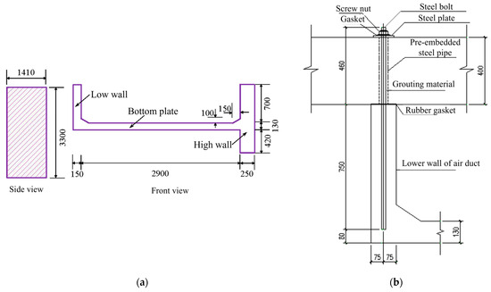
Figure 2.
Dimensions of prefabricated RC segment and assembly node detail (unit: mm): (a) Prefabricated RC segment; (b) Assembly node detail.

Table 1.
Material properties of PAAD.
The assembled RC segments are fixed by the assembly node, as shown in Figure 2b, which mainly includes the steel bolt, pre-embedded steel pipe, and grouting material. The compressive and tensile strengths of the grouting material are 30 MPa and 2.3 MPa, respectively, and the diameter of the bolt is 22 mm. The bolt holes with 50 mm diameter are drilled in the existing slab of the subway station, which are employed for installing the high and low walls of the PAAD. Moreover, the steel pipe with 2.5 mm wall thickness is also pre-embedded in the high and low walls of the PAAD.
3. Mechanical Performance Investigation of Prefabricated Assembly Air Ducts Subject to Assembly and Grouting Defects
Finite element analysis is employed to analyze the influence of assembly and grouting defects on the mechanical performance of the prefabricated assembly air duct (PAAD) in the subway station, including the stress distribution of the assembled segment and sleeve grouting connection and the displacement of the assembled segment.
3.1. Numerical Model and Material Properties
Figure 3 demonstrates the numerical models for investigating the mechanical performance of the PAAD, in which the solid element is employed for simulating all the bolt, sleeve, concrete, and grouting materials; the steel element is adopted for simulating steel reinforcements; and the bond slip characteristics are considered at the interface between steel and concrete. In the numerical model, the assembled RC segments are suspended at the center plate using the assembly node based on the practical construction shown in the aforementioned Figure 1, in which the center panels are fully constrained in the X, Y, and Z directions for numerical simulation. Moreover, a 1.2 kPa wind pressure and 2 kPa internal maintenance load are applied to the PAAD for analyzing its mechanical performance during operation [24], and the aforementioned material properties shown in Table 1 are adopted in the numerical analysis.
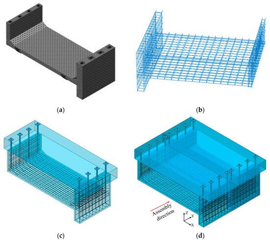
Figure 3.
Numerical models for investigating the mechanical performance of PAAD: (a) individual segment; (b) reinforcements in segment; (c) individual segment with sleeve grouting connection; (d) assembled segment with sleeve grouting connection.
Numerical analysis is implemented to investigate the mechanical performance of the PAAD influenced by the assembly error defects and sleeve grouting defects, in which all the simulated numerical models with and without defects are listed in Table 2. The grouting defects in the sleeve grouting connection are shown in Figure 4, in which the top, middle, and bottom defects represent the grouting defects located at the top, middle, and bottom positions of the connection joint, respectively, and the eccentric defect denotes the deviation of the steel bolt and sleeve. Moreover, the aforementioned grouting defects are probably caused by grouting leakage with a loose top sealing or port, air inside the sleeve, debris blocking at the sleeve bottom, or an inaccurately positioned sleeve, respectively. In the numerical analysis, the assembly error defects are, respectively, assumed as 2 mm, 5 mm, and 10 mm along the assembly direction, all the lengths of the grouting defects at the top, middle, and bottom positions of the sleeve grouting connection are assumed as 20 mm, and the eccentric defect in the sleeve grouting connection is assumed as 5 mm.
Table 2.
Numerical models of PAAD.
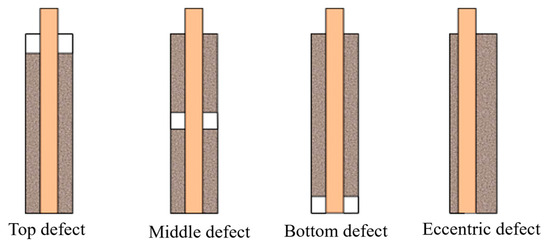
Figure 4.
Grouting defects in the sleeve grouting connection.
3.2. Mechanical Performance of PAAD Without Defects
3.2.1. Stresses of Assembled Segments Without Defects After Sleeve Grouting Process
Figure 5 demonstrates the stress distributions of the individual segment and assembled segments without defects after the sleeve grouting process. Both the individual segment and assembled segments are subjected to tensile stress, which is symmetrically distributed and gradually decreases from the middle to both sides. Moreover, the stress concentration occurs at the sleeve grouting connection in both segments, in which the maximum tensile stress of the individual segment is 0.6 MPa, and that of the assembled segment without defects is 1.5 MPa. This implies that the assembly construction increases the tensile stress of the segment, in which the maximum tensile stresses of the assembled segments without defects are less than the tensile strength of concrete at 2.2 MPa.
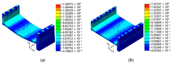
Figure 5.
Stress distributions of individual segment and assembled segment without defects (unit: N/mm2): (a) individual segment; (b) assembled segments.
3.2.2. Stresses of Sleeve Grouting Connection Joint Without Defects
Figure 6 demonstrates the stress distributions of the steel bolt and grouting material in the sleeve grouting connection joint without defects. Both the steel bolt and grouting material are subject to tensile stress; the tensile stress of the steel bolt decreases from the middle to both sides, and that of the grouting material gradually increases from top to bottom, in which the maximum tensile stress of the steel bolt is located in the middle of the steel bolt, and that of the grouting material is located at the bottom of grouting material. Moreover, the maximum tensile stresses of the aforementioned steel bolt and grouting material are 4.2 MPa and 0.8 MPa, respectively, which are less than the tensile strengths of the steel bolt and grouting material.
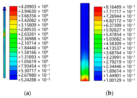
Figure 6.
Stress distributions of sleeve grouting connection without defects (unit: N/mm2): (a) bolt; (b) grouting material.
3.2.3. Displacement of Assembled Segment Without Defects After Sleeve Grouting Process
Figure 7 demonstrates the vertical displacement of the assembled segments without defects after the sleeve grouting process compared with that of the cast-in-place segment. It can be obviously seen that the vertical displacements of both the assembled and cast-in-place segments are symmetrically distributed, in which the vertical displacements of the low and high walls are significantly less than that of the bottom plate in both segments. Moreover, the maximum vertical displacements of the assembled and cast-in-place segments are 0.161 mm and 0.056 mm, respectively, both of which are located in the middle of the bottom plate and met the safety requirements.
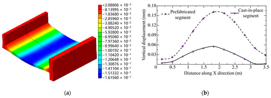
Figure 7.
Vertical displacement of cast-in-place and assembled segments without defects (unit: mm): (a) displacement distribution; (b) displacement curves.
3.3. Mechanical Performance of PAAD with Assembly Error Defects
3.3.1. Stress of Assembled Segments with Assembly Error After Sleeve Grouting Process
Figure 8 shows the stress curves of the assembled segments considering the defects of the varied assembly errors of 2 mm, 5 mm, and 10 mm compared with those of the assembled segments without defects, in which the assembly error defect is assumed along the assembly direction (Y direction). All the assembled segments with the varied assembly errors are subject to tensile stress in the horizontal direction, and they are subject to both the tensile and compressive stresses in the vertical direction, in which the horizontal stresses are greater than the vertical stresses. Moreover, the horizontal and vertical stress curves of the assembled segments with 2 mm and 5 mm assembly errors are consistent with those of the assembled segments without defects, in which the maximum horizontal and vertical stresses occur at the assembly contact surface. In addition, the stress curve of the assembled segments with 10 mm assembly error is varied from those of the aforementioned assembled segments with 2 mm and 5 mm assembly errors.
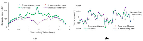
Figure 8.
Stress curves of the assembled segments considering the defects of varied assembly errors: (a) horizontal stress; (b) vertical stress.
Figure 9 demonstrates the stress distribution of the assembled segments with assembly error defects after the sleeve grouting process, in which a 5 mm assembly error defect is assumed along the assembly direction (Y direction). It can be clearly seen that the assembled segments are also subjected to tensile stress, which is symmetrically distributed and decreases from the middle to both sides. Moreover, the stress concentration occurs at the sleeve grouting connection joint, and the maximum tensile stress of the assembled segments is 1.6 MPa, a little increased from the aforementioned 1.5 MPa maximum tensile stress of the assembled segments without defects. This implies that the assembly error defect has a small impact on the mechanical performance of the PAAD, in which the maximum tensile stress of the assembled segments with an assembly error defect is also less than the tensile strength of concrete at 2.2 MPa, satisfying the safety requirements for use.
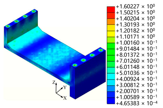
Figure 9.
Stress distribution of assembled segment with assembly error defects.
3.3.2. Displacement of Assembled Segments with Assembly Error After Sleeve Grouting
Figure 10 shows the horizontal and vertical displacements of the assembled segments considering the defects of the varied assembly errors of 2 mm, 5 mm, and 10 mm compared with those of the assembled segments without defects, in which the assembly error defect is assumed along the assembly direction (Y direction). The horizontal and vertical displacement curves of the assembled segments with 2 mm assembly error are consistent with those of the assembled segments without defects, in which both the smallest horizontal displacement and the largest vertical displacement occur at the assembly contact surface. Moreover, the vertical displacement curve of the assembled segments with a 5 mm assembly error is consistent with that of the assembled segment with a 10 mm assembly error, in which both minimum vertical displacements occur at the assembly contact surface, and both the horizontal displacements undergo a sudden change, with the maximum horizontal displacements occurring at the assembly contact surface. Especially, all the vertical displacements of the assembled segments with and without assembly errors are greater than their horizontal displacements, in which all the vertical and horizontal displacements are, respectively, less than 0.18 mm and 0.002 mm, implying that the assembly error has almost no impact on the deformation of the assembled segments.
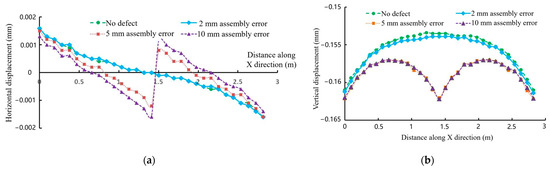
Figure 10.
Displacement curves of the assembled segment considering the defects with varied assembly errors: (a) horizontal displacement; (b) vertical displacement.
Figure 11 demonstrates the displacement distributions of the assembled segments with assembly error defects after the sleeve grouting process, in which the assembled segments have a 5 mm assembly error defect along the assembly direction (Y direction). It is obvious that the vertical displacement of the assembled segments is significantly greater than their horizontal displacement, in which the maximum horizontal displacement of the assembled segments occurs at the assembly contact surface, and there is a sudden change in their horizontal displacement distribution. Especially, the maximum horizontal and vertical displacements of the assembled segments are less than 0.002 mm and 0.17 mm, respectively, implying that the 5 mm assembly error has little impact on the deformation of the assembled segments. In addition, the horizontal displacement of the assembled segments decreases with the increasing assembly error, and the location of the maximum horizontal displacement position shifts with changes in the assembly error.
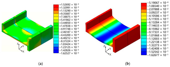
Figure 11.
Displacement distributions of assembled segments with assembly error defects: (a) horizontal displacement; (b) vertical displacement.
3.4. Mechanical Performance of Sleeve Grouting Connection Joint with Grouting Defects
Figure 12 demonstrates the stresses of the sleeve grouting connection joint with the aforementioned typical grouting defects shown in Figure 4. It can be clearly seen that all the sleeve grouting connection joints are subject to tensile stress, with obvious stress concentration around the bolt hole, in which the maximum tensile stresses of these sleeve grouting connection joints with grouting defects are located at the edge of the bolt hole. Moreover, the maximum tensile stresses of the concrete in the sleeve grouting connection with top, middle, bottom, and eccentric defects are 1.79 MPa, 1.76 MPa, 2.42 MPa, and 1.64 MPa, respectively, in which the aforementioned 2.42 MPa is greater than the tensile strength of concrete at 2.2 MPa. This implies that the bottom defects in the sleeve grouting connection joint can induce the failure of the concrete around the connection joint, and a strengthening treatment is required for ensuring the structure’s safety and reliability.
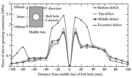
Figure 12.
Stresses of sleeve grouting connection with grouting defects.
4. Conclusions
In this paper, the mechanical performance of a prefabricated assembly air duct (PAAD) in a subway station is numerically investigated, focusing on the influence of grouting defects in the sleeve grouting connection and assembly error defects along the assembly direction, and the following conclusions are obtained:
(1) The internal stress of the PAAD is symmetrically distributed and decreases from the middle to both sides due to the presence of wind pressure and internal maintenance load, and the stress distribution of the PAAD with assembly error defects is similar to a PAAD without defects, in which the assembly error defects almost have no impact on the mechanical performance of the PAAD, satisfying the safety requirements for use.
(2) The grouting defects in the sleeve grouting connection can influence the mechanical performance of the PAAD, in which the maximum tensile stress of the concrete in the sleeve grouting connection with a 20 mm-long bottom grouting defect is greater than the tensile strengths of that concrete, which are 2.42 MPa and 2.2 MPa, respectively, and a strengthening treatment is thus required for ensuring the structure’s safety and reliability.
(3) The displacements of both assembled and cast-in-place segments are symmetrically distributed, and the maximum vertical displacements of the assembled and cast-in-place segments are 0.161 mm and 0.056 mm, respectively, both of which are located in the middle of the bottom plate and met the safety requirements.
Author Contributions
Conceptualization, S.B., J.Z. and Y.Z.; validation, S.B. and J.Z.; investigation, S.B. and Y.Z.; data curation, J.Z. and Y.Z.; writing—original draft preparation, S.B.; writing—review and editing, Y.Z. All authors have read and agreed to the published version of the manuscript.
Funding
This research received no external funding.
Data Availability Statement
Data are contained within the article.
Conflicts of Interest
The authors declare no conflicts of interest.
Abbreviations
The following abbreviations are used in this manuscript:
| PAAD | Prefabricated Assembly Air Duct |
References
- Cheng, Y.; Liu, X.Y. Research on the pressure distribution law of synchronous grouting in shield tunnels and the force on segments. Buildings 2024, 14, 1099. [Google Scholar] [CrossRef]
- Tao, L.J.; Zhang, Y.; Zhao, X.; Bian, J.; Chen, X.H.; An, S.; Han, X.C. Group effect of pipe jacking in silty sand. J. Geotech. Geoenviron. Eng. 2021, 147, 05021012. [Google Scholar] [CrossRef]
- Ma, M.L.; Han, L.; Wu, Y.H.; Li, Q.Y.; Zhang, Y.X. Behavioral investigations of three parallel large reinforced concrete circular pipes with the construction of pipe jacking. Appl. Sci. 2023, 13, 8901. [Google Scholar] [CrossRef]
- Belcher, E.J.; Abraham, Y.S. Lifecycle applications of building information modeling for transportation infrastructure projects. Buildings 2023, 13, 2300. [Google Scholar] [CrossRef]
- Xu, B.B.; Yang, R.L.; Dai, H.; Dong, Z.C.; Zhang, Y.X. Behavior of horizontal-directional drilling for multi-pilot heading pretreating blind spots in pipe jacking construction. Sustainability 2024, 16, 314. [Google Scholar] [CrossRef]
- Tong, L.; Zhou, H.; Liu, H.; Ding, X. Failure envelope of an underground rectangular pipe gallery in clay under pipe–soil interactions. Int. J. Geomech. 2023, 23, 402–410. [Google Scholar] [CrossRef]
- Wang, S.Q.; Feng, D.C.; Wu, G. Design and bearing capacity test of prefabricated high-strength thin concrete segments for reinforcing underground box culverts. Eng. Fail. Anal. 2022, 142, 106844. [Google Scholar] [CrossRef]
- Wang, L.; Chen, X.S.; Su, D.; Zhou, W.P.; Sun, B.; Pan, J.Y.; Wu, Y.Z.; Feng, M. Construction of a super-large prefabricated rectangular tunnel beneath a box culvert using pipe jacking: A case study. Tunn. Undergr. Space Technol. 2024, 152, 105913. [Google Scholar] [CrossRef]
- Yi, P.; Yi, D.; Wu, W.; Bao, Y.; Guo, R. Mechanical performance test and finite element analysis of prefabricated utility tunnel L-shaped joint. Struct. Des. Tall Spec. Build. 2020, 29, e1748. [Google Scholar]
- Conforti, A.; Trabucchi, I.; Tiberti, G.; Plizzari, G.A.; Caratelli, A.; Meda, A. Precast tunnel segments reinforced by macro-synthetic fibers. Tunn. Undergr. Space Technol. 2017, 63, 1–11. [Google Scholar] [CrossRef]
- Xu, P.F.; Wei, Y.J.; Yang, Y.Y.; Zhou, X. Application of fabricated corrugated steel plate in subway tunnel supporting structure. Case Stud. Constr. Mater. 2022, 17, e01323. [Google Scholar] [CrossRef]
- Yang, X.R.; Lin, F. Research on prefabricated metro station structure and key assembly technologies. Tunn. Undergr. Space Technol. 2024, 153, 106029. [Google Scholar] [CrossRef]
- Shi, C.; Li, J.; Xu, X. Full-scale tests on smoke temperature distribution in long-large subway tunnels with longitudinal mechanical ventilation. Tunn. Undergr. Space Technol. 2021, 109, 103784. [Google Scholar] [CrossRef]
- Benayoune, A.; Samad, A.A.A.; Trikha, D.N.; Abdullah Abang Ali, A.; Ashrabov, A.A. Structural behaviour of eccentrically loaded precast sandwich panels. Constr. Build. Mater. 2006, 20, 713–724. [Google Scholar] [CrossRef]
- Ueda, T.N.; Stitmannaithum, B. Shear strength of precast prestressed hollow slabs with concrete topping. ACI Struct. J. 1991, 88, 402–410. [Google Scholar] [CrossRef] [PubMed]
- Debiasi, E.; Gajo, A.; Zonta, D. On the seismic response of shallow-buried rectangular structures. Tunn. Undergr. Space Technol. 2013, 38, 99–113. [Google Scholar] [CrossRef]
- Gao, S.; Zhao, W.G.; Zhao, G.T.; Wang, S.P.; Xie, K.Z. Numerical study on seismic performance of a prefabricated subway station considering the influence of construction process. Structures 2024, 69, 107218. [Google Scholar] [CrossRef]
- Di Carlo, F.; Meda, A.; Rinaldi, Z. Design procedure for precast fibre-reinforced concrete segments in tunnel lining construction. Struct. Concr. 2016, 17, 747–759. [Google Scholar] [CrossRef]
- Meda, A.; Rinaldi, Z.; Spagnuolo, S.; De Rivaz, B.; Giamundo, N. Hybrid precast tunnel segments in fiber reinforced concrete with glass fiber reinforced bars. Tunn. Undergr. Space Technol. 2019, 86, 100–112. [Google Scholar] [CrossRef]
- Du, Y.X.; Sun, X.L.; Yang, J.; Wu, Z.Q.; Bian, D.C. Research on the sleeve grouting fullness testing of prefabricated structures based on piezoelectric method. KSCE J. Civ. Eng. 2024, 28, 1928–1946. [Google Scholar] [CrossRef]
- Li, D.S.; Liu, H. Detection of sleeve grouting connection defects in fabricated structural joints based on ultrasonic guided waves. Smart Mater. Struct. 2019, 28, 085033. [Google Scholar] [CrossRef]
- Zhao, J.; Yin, L.L.; Chen, J.; Yang, Y.Z.; Zhu, Y.H.; Yang, B. Analysis of the mechanical performance of sleeve considering the different distributions of grouting defects. Buildings 2023, 13, 2873. [Google Scholar] [CrossRef]
- Nguyen, D.C.; Jeon, C.H.; Roh, G.; Shim, C.S. BIM-based preassembly analysis for design for manufacturing and assembly of prefabricated bridges. Autom. Constr. 2024, 160, 105338. [Google Scholar] [CrossRef]
- GB 50157—2013; Code for Design of Metro. China National Standard. Standardization Administration of China: Beijing, China, 2014.
Disclaimer/Publisher’s Note: The statements, opinions and data contained in all publications are solely those of the individual author(s) and contributor(s) and not of MDPI and/or the editor(s). MDPI and/or the editor(s) disclaim responsibility for any injury to people or property resulting from any ideas, methods, instructions or products referred to in the content. |
© 2025 by the authors. Licensee MDPI, Basel, Switzerland. This article is an open access article distributed under the terms and conditions of the Creative Commons Attribution (CC BY) license (https://creativecommons.org/licenses/by/4.0/).