Article

Numerical Simulation of Surrounding Rock Vibration and Damage Characteristics Induced by Blasting Construction in Bifurcated Small-Spacing Tunnels

1
School of Hydraulic and Civil Engineering, Ludong University, Yantai 264025, China
2
China Construction Third Engineering Bureau Urban Construction Co., Ltd., Changchun 130500, China
*
Author to whom correspondence should be addressed.
Buildings 2025, 15(15), 2737; https://doi.org/10.3390/buildings15152737
Submission received: 19 June 2025 / Revised: 18 July 2025 / Accepted: 29 July 2025 / Published: 3 August 2025
(This article belongs to the Section Construction Management, and Computers & Digitization)

Abstract

The stability of the intermediate rock wall in the blasting construction of bifurcated small-spacing tunnels directly affects the construction safety of the tunnel structure. Clarifying the damage characteristics of the intermediate rock wall has significant engineering value for ensuring the safe and efficient construction of bifurcated tunnels. Based on the Tashan North Road Expressway Tunnel Project, this paper investigated the damage characteristics of the intermediate rock wall in bifurcated tunnels under different blasting construction schemes, using numerical simulation methods to account for the combined effects of in situ stress and blasting loads. The results were validated using comparisons with the measured damage depth of the surrounding rock in the ramp tunnels. The results indicate that the closer the location is to the starting point of the bifurcated tunnel, the thinner the intermediate rock wall and the more severe the damage to the surrounding rock. When the thickness of the intermediate rock wall exceeds 4.2 m, the damage zone does not penetrate through the wall. The damage to the intermediate rock wall exhibits an asymmetric “U”-shaped distribution, with greater damage on the side of the trailing tunnel at the section of the haunch and sidewall, while the opposite is true at the section of the springing. During each excavation step of the ramp and main-line tunnels, the damage to the intermediate rock wall is primarily induced by blasting loads. As construction progresses, the damage to the rock wall increases progressively under the combined effects of blasting loads and the excavation space effect. In the construction of bifurcated tunnels, the greater the distance between the headings of the leading and trailing tunnels is, the less damage will be inflicted on the intermediate rock wall. Constructing the tunnel with a larger cross-sectional area first will cause more damage to the intermediate rock wall. When the bench method is employed, an increase in the bench length leads to a reduction in the damage to the intermediate rock wall. The findings provide valuable insights for the selection of construction schemes and the protection of the intermediate rock wall when applying the bench method in the construction of bifurcated small-spacing tunnels.

1. Introduction

In the construction of tunnels and underground engineering projects, the drilling and blasting method is widely adopted due to its cost-effectiveness, high efficiency, and excellent adaptability. However, the blasting process inevitably induces vibrations and damage to the surrounding rock, which not only jeopardizes construction safety but also impacts the long-term stability of the structures. With the continuous expansion of underground engineering projects, the construction environment has become increasingly complex, such as adjacent construction in urban underground projects and the growing number of closely spaced tunnel projects. These factors undoubtedly demand higher precision, efficiency, and safety in tunnel blasting techniques [1,2,3]. In recent years, domestic and international scholars have made significant progress in fields including the characteristics of tunnel blasting vibrations, the optimization design of blasting techniques, and the control of surrounding rock damage. Nevertheless, studies on the damage to tunnel surrounding rock continue to face significant challenges and necessitate further in-depth investigation [4].
To address the challenges associated with tunnel blasting construction, extensive research has been conducted by scholars, yielding substantial practical outcomes. For instance, in the study of blasting vibration characteristics, Guan et al. [5,6] demonstrated that near-field vibrations during blasting are predominantly induced by perimeter hole detonations, while far-field vibrations are governed by the charge weight of cut holes and the presence of free surfaces. Wang et al. [7], by analyzing on-site monitoring data, identified distinct vibration attenuation characteristics across various structural elements, including lower bench surfaces, sidewalls of excavated tunnels, and closely spaced neighboring tunnels. Xu et al. [8] investigated the influence of the spatial distribution of tunnel groups on stress redistribution and the propagation characteristics of blasting waves using a series of field blasting experiments and proposed the peak horizontal vibration velocity as a safety criterion for underground engineering. To achieve accurate predictions of blasting vibration responses, researchers have developed a variety of enhanced methods rooted in empirical formulas, thereby improving the accuracy of blasting vibration predictions [5,7]. Furthermore, Lu et al. [9] highlighted the necessity of accounting for the transient characteristics of in situ stress release and the consequent dynamic response of the surrounding rock in addressing challenges related to tunnel blasting excavation, a critical aspect for understanding the coupled effects of blasting vibrations and in situ stress. In terms of blasting parameter design, Xu et al. [10] investigated multi-hole cumulative blasting technology using model tests and numerical simulations, demonstrating that this technique facilitates the formation of directional penetration cracks while minimizing damage to the surrounding rock, offering valuable insights for addressing overbreak and underbreak issues in tunnels. Ding et al. [11] revealed the rock fragmentation characteristics under in situ stress redistribution-assisted blasting using numerical simulations and proposed that the rational utilization of in situ stress redistribution not only enhances rock fragmentation but also reduces explosive consumption. Li et al. [12] studied the cracking and damage of rock during smooth blasting and pre-splitting blasting of tunnel contours using experiments and numerical simulations, offering references for optimizing blasting parameters. In the field of surrounding rock damage mechanisms and control, Yan et al. [13] utilized acoustic wave velocity testing and EDZ analysis to categorize the damage zones induced by blasting excavation in deep-buried tunnels into inner and outer damage zones and further investigated the formation mechanisms of these distinct damage zones. Based on the Jinping II Hydropower Station auxiliary tunnel project, Chen et al. [14] analyzed the main influencing factors of blasting vibration-induced surrounding rock damage zone by combining on-site rock mass wave velocity testing and numerical simulation. Verma et al. [15] established an empirical formula for estimating the surrounding rock damage around tunnels using large-scale field investigations. Li et al. [16] employed the finite-discrete element method to investigate the evolution of blasting-induced damage zones, providing a theoretical basis for controlling excavation damage in tunnels. Wang et al. [17] constructed a tunnel model within jointed rock mass to study the dynamic damage and failure processes of jointed rock mass under blasting loads, along with their corresponding dynamic failure modes. Ji et al. [18], Li et al. [19], Zhao et al. [20], and Zhu et al. [21] investigated the cumulative damage processes and the evolution of damage in rocks under the combined influence of multiple blasting events, in situ stress, and cyclic blasting loads. Fu et al. [22] proposed a wave velocity field inversion imaging method to quantify the characteristics of blasting damage zones and revealed the relationship between charge quantity and damage zone size. Wang et al. [23] conducted large-scale physical model tests to study the stress and deformation characteristics of unlined tunnels, bolt-reinforced tunnels, and lined tunnels under the coupled effects of blast waves and in situ stress, providing a reference for the selection of blasting vibration control measures. Furthermore, with the rapid advancement of computer technology, the future application of computer vision techniques for automated mapping and quantitative characterization of blast-induced fractures and damage zones in surrounding rock is expected to achieve significant progress [24,25].
Due to the unique and complex structural characteristics of bifurcated small-spacing tunnels, mitigating vibration-induced damage to the surrounding rock during blasting operations is of critical importance, particularly in ensuring the safety and stability of the intermediate rock wall. Although some studies have been conducted on the protection and vibration reduction measures for the intermediate rock wall [2,26,27,28], research on the cumulative effects and mutual influence mechanisms of surrounding rock damage under different blasting sequences, time intervals, and complex geological conditions in bifurcated small-spacing tunnels is still insufficient. Therefore, this paper, based on the Tashan North Road Expressway Tunnel Project, comprehensively considers the combined effects of in situ stress and blasting loads. Using numerical simulation methods, the damage characteristics of the intermediate rock wall in the bifurcated tunnel under different blasting construction schemes are studied, and the results are compared and validated with the measured damage depths of the surrounding rock in the ramp tunnel. This provides theoretical support for optimizing the construction scheme of this project and offers valuable experience for similar engineering projects.

2. Engineering Prototype

2.1. Engineering Project Overview

The Yantai Expressway Tashan North Road Construction Project is situated in Shandong Province, China. The project predominantly comprises tunnels, including the Zhenshan Section, Tashan Section, and Eastern Extension Section of the Tashan North Road Tunnel, totaling three sections. This study primarily focuses on the Zhenshan Section tunnel project, which features an entrance and exit ramp connected to the existing Hongqi West Road Viaduct. The mainline of the Zhenshan Section tunnel spans approximately 2.66 km, with a design speed of 80 km/h. The main tunnel features a three-lane cross-section, whereas the ramp tunnel is designed with a two-lane cross-section. The bifurcated small-spacing tunnel section gradually expands from three lanes to five lanes before diverging into a two-lane ramp tunnel and a three-lane main tunnel. The plan and cross-sectional views of the bifurcated small-spacing tunnel are shown in Figure 1.

2.2. Geological Conditions

This study focuses on the left-line tunnel project. The left-line tunnel extends a total length of 2325.00 m, with a design elevation varying between 44.16 and 89.51 m, while the overlying rock and soil thickness varies from 7.40 to 102.32 m. The left-line ramp tunnel spans approximately 1038.07 m, with a design elevation ranging between 86.58 and 95.83 m, while the overlying rock and soil thickness ranges from 0.50 to 67.87 m. The bifurcated small-spacing tunnel section extends from Z2K16+682.51 to Z2K16+827.00, with a burial depth varying between 39.76 and 40.74 m. The surrounding rock is predominantly composed of moderately weathered schist and granite. The rock exhibits well-developed weathering fractures, with the rock mass being relatively fragmented and classified as soft rock. The surrounding rock is categorized as Grade IV. The geological profile of the bifurcated small-spacing tunnel section is shown in Figure 2.

3. Determination of Blasting Load and Damage Criterion for Surrounding Rock

3.1. Application Method of the Blasting Load

The blasting destruction of rock is a transient process characterized by high temperatures and pressures, typically occurring within tens of microseconds to tens of milliseconds. This renders the study of the processes and mechanisms underlying rock blasting destruction highly challenging. During blasting operations, with increasing distance from the blast hole center, the surrounding rock transitions from fractured and fragmented zones to intact rock mass, and its mechanical properties evolve from fluid–plastic to elastoplastic and ultimately to elastic states. Current numerical methods face challenges in accurately capturing the entire process of surrounding rock blasting, thus rendering the determination and application methods of blasting loads of critical importance. Currently, based on the specific research objectives in tunnel blasting construction, the primary methods for applying blasting loads in numerical simulations involve the blast hole surface and the excavation contour surface. A concise overview of these methods is presented below:
(1)
Application of blasting loads on the blast hole surface. This approach primarily simulates the detonation process of explosives by employing the Jones–Wilkins–Lee (JWL) equation of state for explosive materials or by applying pressure loads on the blast hole wall to investigate the damage to surrounding rock and the propagation of vibrations within the near-field zone of the blast hole. For example, Li et al. [29] developed the blasting load time–history curve using the JWL equation of state and conducted investigations on rock damage. Guan et al. [30] investigated the vibration damage characteristics of tunnel middle partitions by employing the JWL equation of state. Meanwhile, Cho et al. [31] utilized the blast hole wall pressure time–history curve to examine the cracking mechanisms of surrounding rock during single-hole blasting. Hu et al. [32] compared tensile-compressive damage models with several widely used blasting damage models using the blast hole wall pressure time–history curve and introduced a novel model for simulating blasting vibration damage. This approach effectively simulates the blasting vibration response of rock masses within the near-field zone of the blast hole for scenarios involving single or a limited number of blast holes. However, when applied to large-scale blasting problems in practical engineering contexts, this method demands excessive computational resources, significantly compromising computational efficiency.
(2)
Application of blasting loads on the excavation contour surface. This method involves scaling down the load acting on the blast hole wall and subsequently applying it across a broader area of the tunnel excavation contour surface to investigate the blasting vibration response in the medium- and far-field zones from the blast hole. For example, Yan et al. [13] employed this method to apply equivalent loads to the excavation contour and investigated the excavation damage zone of the tunnel under transient in situ stress unloading conditions. Lu et al. [9] applied the equivalent load to the elastic boundary and derived the load history to simulate vibrations in the medium- and far-field zones. Shin et al. [33] scaled down the load on the blast hole wall and applied it to the outer boundary of the blasting plastic zone. This approach eliminates the need for establishing a blast hole model and is particularly suitable for simulating the vibration response of surrounding rock in the medium- and far-field zones under multi-hole blasting conditions. However, it has limitations in addressing issues such as rock fragmentation and blasting damage in the near-field zone of the blast hole.
This study focuses on investigating the vibration damage to the intermediate rock wall resulting from blasting construction in the bifurcated small-spacing tunnel section, to facilitate the determination of an optimal construction scheme. Based on the previously mentioned analysis, the method of applying blasting loads to the excavation contour surface is demonstrated to be more suitable.

3.2. Form and Magnitude of Blasting Load

Although the blasting damage process in tunnel surrounding rock occurs over an extremely short duration, the form and magnitude of the blasting load exhibit temporal variations. Given the complex high-temperature and high-pressure conditions within the blast hole during the blasting process, direct measurement of the blasting load variation history inside the blast hole is challenging to implement widely. Currently, semi-theoretical and semi-empirical exponential decay loads and triangular loads are predominantly employed [34,35,36]. Owing to the heavy reliance of parameter selection in exponential blasting loads on field measurement data, triangular blasting loads have gained broader application, as shown in Figure 3.
In tunnel engineering blasting operations, cylindrical charges in blast holes are typically employed. The average detonation pressure acting on the blast hole wall is determined using Equation (1) [37].
P 0 = ρ D 2 2 1 + γ
Here, ρ is the explosive density; D is the detonation velocity of the explosive; and γ is the isentropic index of the explosive, approximately taken as γ = 3.0. When coupled charge is used, the pressure acting on the blast hole wall is the detonation pressure P0.
When decoupled charge is used, the pressure acting on the blast hole wall is calculated using Equation (2).
P 0 = ρ D 2 2 1 + γ 1 λ 2 γ   The   decoupling   coefficient   is   small ρ D 2 2 1 + γ ν γ P K γ ν γ 1 λ 2 γ   The   decoupling   coefficient   is   large
Here, λ is the decoupling coefficient, ν is the isentropic index of the detonation gas, and PK is the critical pressure of the explosive.
Under typical cylindrical charge configurations in blast holes, the crushing zone of the surrounding rock extends 3 to 5 times the charge radius, while the fracture zone extends 10 to 15 times the charge radius [38]. By considering the crushing zone and fracture zone as the blast source area, the blasting load applied to the elastic boundary of the blast source area is determined using Equation (3).
P be = P 0 r 0 r 1 2 + μ 1 μ r 1 r 2 2 μ 1 μ
Here, r0 is the blast hole radius, r1 is the crushing zone radius, r2 is the fracture zone radius, and µ is the Poisson’s ratio of the rock mass.
When the blasting load on the elastic boundary of the blast source area is equivalently distributed across the plane connecting the centers of the blast sources, namely, the excavation contour surface, the magnitude of the equivalent load can be determined using Equation (4).
P e = 2 r 2 s P be
Here, s is the distance between the centers of the blast holes.

3.3. Damage Criterion for Surrounding Rock

In practical engineering applications, the surrounding rock of tunnels is characterized by numerous micro-cracks and micro-fractures, which propagate and interconnect under blasting loads, resulting in strength degradation and diminished bearing capacity. In current practice, the damage variables employed in surrounding rock damage models are typically expressed as functions of crack density, with crack density predominantly determined through probability distributions, thereby complicating parameter determination. Given that the surrounding rock experiences increasing plastic strain and damage with rising blasting loads, this study adopts the Mohr–Coulomb criterion, widely utilized in underground engineering, as the basis for assessing surrounding rock damage.
The Mohr-Coulomb criterion models the surrounding rock as ideally plastic and is classified as a shear failure criterion. The damage criterion is expressed as follows:
f s = σ 1 σ 3 σ 1 + σ 3 sin φ 2 c cos φ = 0
where σ1 is the maximum principal stress (MPa), σ3 is the minimum principal stress (MPa), φ is the internal friction angle (°), and c is the cohesion. When fs ≤ 0, shear damage occurs in the surrounding rock.
When the maximum principal stress in the surrounding rock attains its tensile strength, tensile damage is initiated. The corresponding damage criterion is expressed as follows:
f t = σ 1 σ t
where σt is the tensile strength of the surrounding rock (MPa). When ft ≤ 0, tensile damage occurs in the surrounding rock.
When the minimum principal stress in the surrounding rock attains its compressive strength, compressive damage is initiated. The corresponding damage criterion is expressed as follows:
f c = σ 3 + σ c
where σc is the compressive strength of the surrounding rock (MPa). When fc ≤ 0, compressive damage occurs in the surrounding rock.

4. Numerical Analysis of Blasting Construction in Bifurcated Tunnels

4.1. Numerical Calculation Model

Based on the engineering data from the Tashan North Zhenshan Tunnel, a numerical model for the bifurcated tunnel was developed. The model dimensions are 100 m in height, 120 m in width, and 60 m in length. Within the numerical model, the bifurcated tunnel is situated at a burial depth of 40 m, with an approximate angle of 17° between the main-line tunnel and the ramp tunnel. The intermediate rock wall between the two tunnels has a minimum thickness of 1.2 m. Excluding the influence of the super-large span section construction, the main-line tunnel and the ramp tunnel are constructed using the top-heading and bench method, with an excavation advance of 2 m per round. The four lateral boundaries of the model are constrained horizontally, the bottom boundary is constrained vertically, while the top boundary remains unconstrained. The numerical model is shown in detail in Figure 4. Considering factors including the face offset distance between the main-line and ramp tunnels, the construction sequence of the main-line and ramp tunnels, and the construction bench length, a comparative analysis of different construction schemes was performed, with a total of seven construction schemes designed. The design of the numerical construction schemes is detailed in Table 1. Finally, by integrating research findings with the actual conditions of the construction site, the goal of optimizing the blasting construction scheme for this tunnel section was successfully achieved.

4.2. Parameters of Numerical Calculation

4.2.1. Calculation Parameters of Surrounding Rock and Support

Given that the construction zone of the bifurcated small-spacing tunnel primarily consists of moderately weathered schist within a 60-m range, where geological conditions exhibit relative homogeneity, the computational parameters were determined based on comprehensive geological investigation data. The relevant calculation parameters are derived from in situ geological investigations and field testing. The initial support structure comprises I18 steel arches and C25 shotcrete, with a shotcrete thickness of 240 mm. The calculation parameters for the surrounding rock and support structure are presented in Table 2.

4.2.2. Calculation Parameters of Blasting Load

To reduce the complexity of the model calculations, the effects of staged delayed blasting and blast hole arrangement during tunnel construction are neglected, and the equivalent blasting load from the blast source area is uniformly distributed across the excavation contour surface. As discussed previously, the blasting load during tunnel construction is modeled using a triangular time history curve. Based on the actual blasting construction scheme for this project, the blast hole diameter is 2r0 = 40 mm, the blast hole spacing is s = 600 mm, a coupled charge configuration is employed, the explosive density is ρ = 1000 kg/m3, the detonation wave velocity is D = 3600 m/s, and the isentropic index is γ = 3. Using Equation (1), the peak blasting load acting on the blast hole wall is determined to be Pb0 = 1620 MPa. Assuming the crushing zone radius r1 is 4 times the charge radius r0, and the fracture zone radius r2 is 12 times the charge radius r0, the blasting load acting on the elastic boundary of the blast source area is calculated using Equation (2) to be Pbe = 9.68 MPa. Using Equation (3), the equivalent load on the excavation contour surface is determined to be Pe = 7.74 MPa. Using comprehensive sensitivity analysis of equivalent loading conditions, the validity of the adopted load parameters has been verified, with results confirming compliance with all stipulated engineering accuracy criteria. Considering the combined effects of in situ stress unloading and blasting loads, the blasting load rise time tr is assumed to be 1 millisecond, the positive pressure duration tb is 10 milliseconds, and the dynamic response calculation time is set to 15 milliseconds [39]. Consequently, the equivalent load applied to the excavation contour surface during the construction process is shown in Figure 5.

4.3. Results and Analysis of Numerical Calculation

Using the above-mentioned numerical model and parameters, the excavation processes for various construction schemes of the bifurcated tunnel (including the face offset distance between the main-line and ramp tunnels, the construction sequence of the main-line and ramp tunnels, and the bench length) were individually simulated. Given the critical role of the intermediate rock wall in the bifurcated tunnel, this section examines the damage characteristics of the intermediate rock wall under blasting loads during the construction of the bifurcated tunnel. Below, the excavation results for the construction scheme involving the ramp tunnel being constructed first, with an upper bench length of 4 m and a face offset distance of 8 m between the ramp and main-line tunnels, are analyzed and discussed. The detailed construction process for this scheme is outlined as follows:
(1)
First, the upper bench of the ramp tunnel is excavated with an advance of 2 m per cycle. After completing 4 m of upper bench excavation, the lower bench is excavated, followed by sequential cyclic excavation of the ramp tunnel.
(2)
Following the excavation of 8 m of the lower bench in the ramp tunnel, the upper bench of the main-line tunnel is excavated with an advance of 2 m per cycle. After completing 4 m of upper bench excavation in the main-line tunnel, the lower bench is excavated.
(3)
A face offset distance of 8 m is maintained between the ramp and main-line tunnels, and both tunnels are advanced simultaneously until the lower bench excavation of the main-line tunnel reaches 20 m, marking the completion of the excavation process.

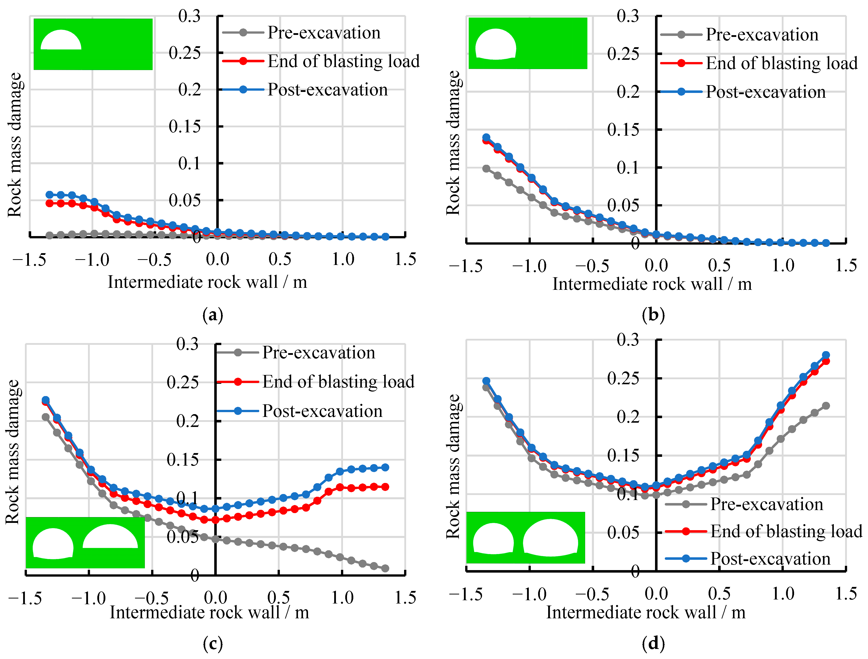
4.3.1. Analysis of the Damage to Intermediate Rock Wall After the Completion of Construction

After the completion of tunnel construction based on the above-mentioned scheme, five observation cross-sections, labeled A, B, C, D, and E, were selected starting from the bifurcation point of the tunnel to analyze the damage to the surrounding rock. These sections are located at distances of 0, 5, 10, 15, and 20 m from the starting point of the bifurcated tunnel, respectively. Based on the damage criteria established in Section 3.3, statistical analysis reveals that blasting vibration-induced damage zones predominantly exhibit shear failure modes, with tensile and compressive failures contributing marginally. Consequently, shear damage has been adopted as the primary evaluation metric for assessing the intermediate rock wall damage under different construction schemes. The damage distribution diagrams of the surrounding rock at each observation cross-section are shown in Figure 6.
As can be seen from Figure 6, the effects of blasting construction on the bifurcated tunnel are predominantly concentrated on the side of the intermediate rock wall, particularly at the tunnel haunch, sidewalls, and spring, where the surrounding rock damage is both severe and extensive. With increasing distance from the starting point of the bifurcated tunnel, the thickness of the intermediate rock wall increases progressively, and the extent and range of surrounding rock damage diminish accordingly. Within 5 m from the starting point, the damage zones of the intermediate rock wall are interconnected, with the rock wall damage being relatively severe. Appropriate safety measures must be implemented during construction. This is primarily due to the relatively thin intermediate rock wall and the creation of a free surface by the excavation of the leading tunnel. Under blasting loads, the reflection of explosive stress waves results in severe and extensive damage to the surrounding rock in this region.
Furthermore, the intermediate rock wall of the bifurcated tunnel was selected as the research object to analyze the damage characteristics of the surrounding rock. Based on the tunnel haunch, sidewall, and spring positions, three longitudinal sections of the intermediate rock wall, including upper, central, and lower, were selected from top to bottom. The damage variation curves of the surrounding rock along different paths at the three longitudinal sections are shown in Figure 7. The damage variation curves of the surrounding rock at the center of the intermediate rock wall thickness are presented in Figure 8.
As can be seen from Figure 7, after cyclic blasting construction, the damage to the surrounding rock diminishes progressively along each path from the excavation contours of the ramp and main-line tunnels toward the center of the rock wall, exhibiting an asymmetric “U”-shaped distribution. Along the height of the intermediate rock wall, the damage is most severe at the central section, followed by the lower section, and least severe at the upper section. Along the tunnel axis direction, sections closer to the bifurcation starting point exhibit a thinner intermediate rock wall and more severe surrounding rock damage. At the upper and center sections, the surrounding rock damage on the trailing main tunnel side is slightly greater than that on the leading ramp tunnel side. At the lower section, the surrounding rock damage on the leading ramp tunnel side exceeds that on the main-line tunnel side. This is primarily attributed to the combined effects of the blasting load and stress redistribution induced by the tunnel excavation spatial effect, which intensifies the damage to the surrounding rock of the leading tunnel.
As can be seen from Figure 8, along the tunnel axis direction, within 5 m from the starting point of the bifurcated tunnel, the damage at the center of the intermediate rock wall thickness is significant in each section, indicating continuous damage to the intermediate rock wall. Beyond 10 m from the bifurcation starting point, damage at the center of the intermediate rock wall thickness is negligible, indicating discontinuous damage to the intermediate rock wall. For instance, when the thickness of the intermediate rock wall in the central section increases from 1.2 m to 2.7 m (a 1.25-fold increase), the damage level of the intermediate rock wall decreases from 0.466 to 0.123, representing a 73.6% reduction. When the thickness exceeds 4.2 m (a 2.5-fold increase), damage at the center of the intermediate rock wall thickness becomes negligible, and the damage zone is discontinuous. These results demonstrate that the thickness of the intermediate rock wall significantly influences the damage to the rock wall. Once the intermediate rock wall reaches a critical thickness, the damage depth ceases to increase, and continuous damage is prevented.

4.3.2. Analysis of the Damage to the Intermediate Rock Wall During the Construction Process

To investigate the damage evolution in the intermediate rock wall during the construction of the bifurcated tunnel, the central section of the rock wall, Path B, was chosen for detailed analysis. The damage distribution curves of the intermediate rock wall during the construction of the upper and lower benches of the ramp and main-line tunnels near Path B are shown in Figure 9. Figure 9 presents the damage to the intermediate rock wall before each excavation step, at the conclusion of the blasting load, and post-construction. The damage distribution curves of the intermediate rock wall after the upper and lower benches of the ramp and main-line tunnels pass through Path B are shown in Figure 10.
As shown in Figure 9 and Figure 10, the excavation of the upper bench in the leading ramp tunnel causes relatively minor damage to the surrounding rock mass. However, a significant increase in damage extent (approximately 1.3 times greater) is observed following the lower bench excavation. It should be noted that at this construction stage, the trailing main-line tunnel remains unexcavated, and the intermediate rock wall has not yet formed. Consequently, the overall damage to the ramp tunnel’s surrounding rock is confined to a limited zone, with no observable impact on the central portion of the prospective intermediate rock wall thickness. Following the construction of the trailing main-line tunnel, significant damage progression occurs in the intermediate rock wall. The damage level on the main-line tunnel side exhibits a two-fold increase after lower bench excavation compared to upper bench excavation. These observations confirm that the trailing tunnel construction, particularly the lower bench excavation, substantially compromises the integrity of the intermediate rock wall. During each excavation step of the ramp and the main-line tunnels, the damage to the intermediate rock wall is primarily caused by the blasting load. The rock wall experiences progressive damage accumulation under the combined effects of dynamic blast loading and excavation spatial effect.

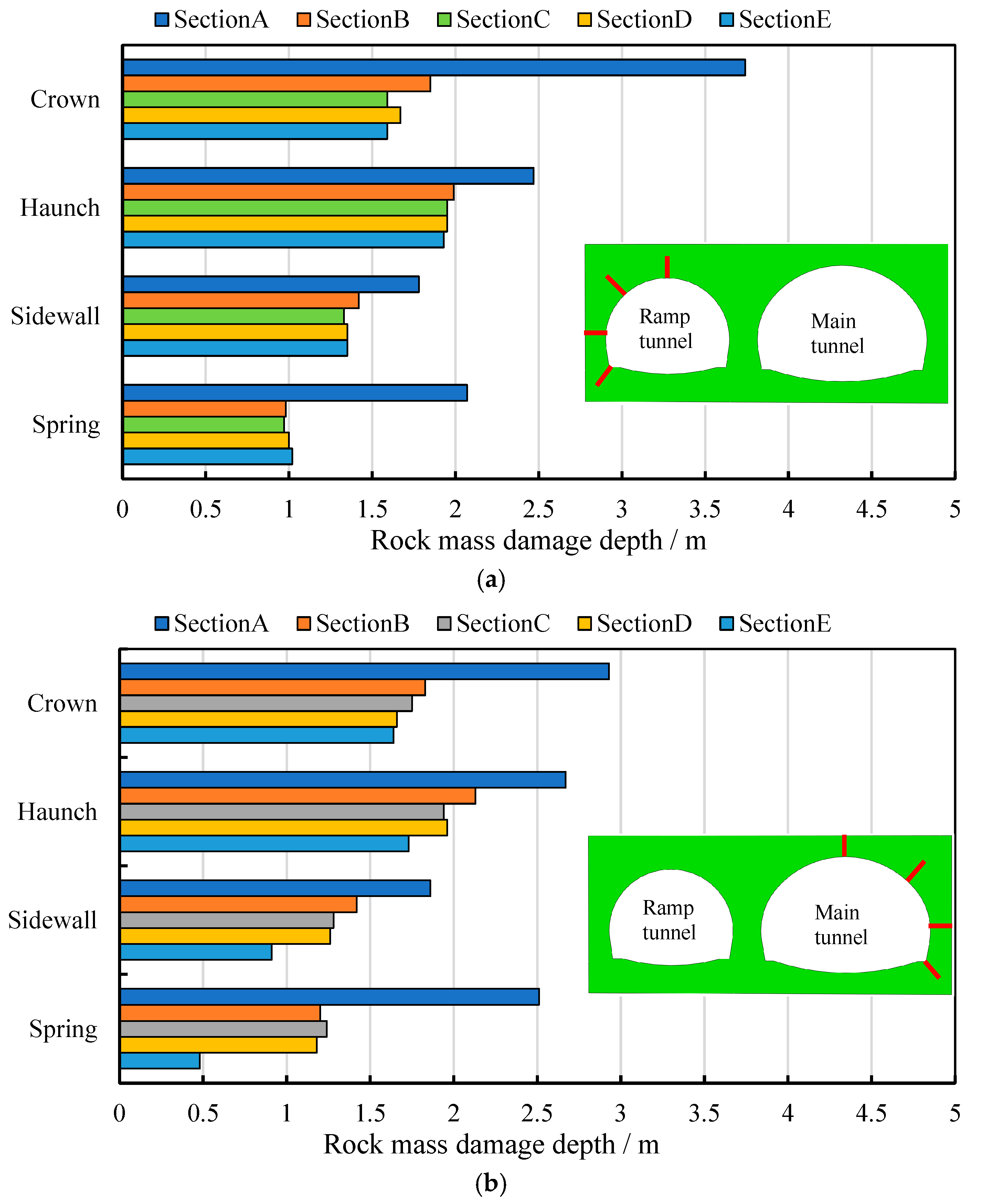
4.3.3. Analysis of the Damage to Surrounding Rock on the Outer Side of Ramp and Main-Line Tunnels

During the investigation of intermediate rock wall damage in the bifurcated tunnel system, comprehensive analyses were performed on surrounding rock damage characteristics for both ramp and main-line tunnels to ensure construction safety. Based on the predetermined observation cross-sections, the damage depths of the surrounding rock at the crown, haunch, sidewall, and spring of the ramp and main-line tunnels at Sections A–E were compared after the completion of construction, as shown in Figure 11.
As shown in Figure 11, the Section A with the thinnest intermediate rock wall (1.2 m thickness) exhibits significantly greater surrounding rock damage depth from crown to springing in both ramp and main-line tunnels compared to other sections. As the thickness of the intermediate rock wall increases, the damage depth of the surrounding rock at corresponding locations across different sections of the leading ramp tunnel shows little variation. Within individual sections, the damage depth is greater at the crown and haunch (approximately 1.5–2.0 m), followed by the sidewall (approximately 1.0–1.5 m), and smallest at the spring (approximately 1.0 m). The damage characteristics of the surrounding rock in the trailing main tunnel are similar to those in the leading ramp tunnel, but the damage depth is slightly greater. Since the lower bench of the main-line tunnel stops at Section E, the surrounding rock at the sidewall and spring are less affected by the excavation spatial effect, resulting in a smaller damage depth. For this project, when the intermediate rock wall is relatively thin (wall thickness of 1.2–2.7 m), the safety of the surrounding rock on both sides of the ramp and main-line tunnels also needs to be carefully considered, and necessary measures should be taken to ensure the surrounding rock’s safety and stability.

4.4. Discussion on Factors Influencing Intermediate Rock Wall Damage

The preceding section analyzed the damage characteristics of both the intermediate rock wall and adjacent surrounding rock under a specific construction scheme for the bifurcated tunnel. In practice, the damage evolution in the intermediate rock wall is governed by multiple interacting factors. This section systematically examines three critical construction parameters: (1) the face offset distance between the leading and trailing tunnels, (2) the excavation sequencing of the leading and trailing tunnels, and (3) the bench excavation length—with emphasis on their impacts on the damage evolution of the intermediate rock wall.

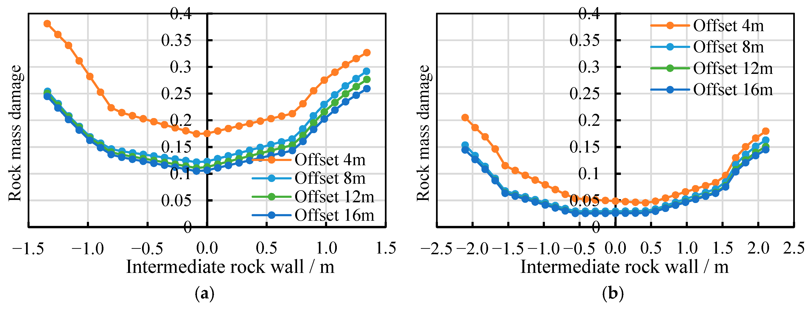
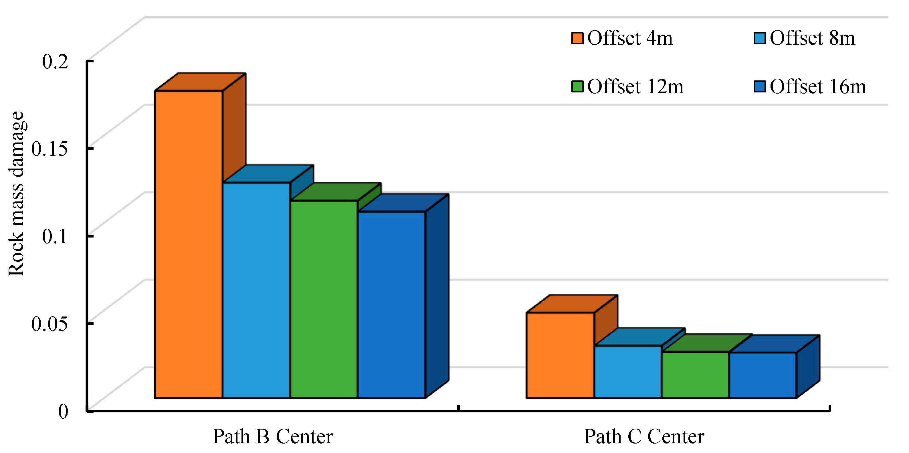
4.4.1. Offset Distance Between Leading and Trailing Tunnel Faces

The numerical simulation evaluated four construction schemes with face offset distances of 4 m, 8 m, 12 m, and 16 m between the leading ramp tunnel and trailing main tunnel, maintaining a constant 4 m bench excavation length, to systematically analyze offset distance effects on intermediate rock wall damage. As established in Section 3.3, rock mass damage exhibits continuous distribution within 5 m from the bifurcation point but becomes localized beyond 10 m. Consequently, the central section along monitoring Paths B and C was selected for detailed assessment. Figure 12 presents computed damage profiles along these paths under varying offset distances, while Figure 13 comparatively illustrates damage evolution at center of the intermediate rock wall thickness.
As shown in Figure 12 and Figure 13, the damage to the intermediate rock wall gradually decreases as the face offset distance between the leading ramp tunnel and the trailing main tunnel increases. When the face offset distance between the two tunnels is 4 m, the damage to the intermediate rock wall is most severe. Upon doubling the face offset distance to 8 m, the damage to the intermediate rock wall is significantly reduced, with a 30.0% reduction in damage at Path B and a 38.8% reduction at Path C at the thickness center of the rock wall. When the face offset distance exceeds 8 m, the damage to the intermediate rock wall no longer shows significant reduction, with less than 10.0% decrease observed at the rock wall thickness center. This behavior primarily stems from the limited spacing between the ramp tunnel and main-line tunnel, which results in a thinner rock wall structure. Notably, smaller face offset distances lead to earlier formation of the intermediate rock wall, subjecting it to simultaneous construction disturbances from both the leading and trailing tunnels. These combined effects amplify damage accumulation and compromise structural safety. Therefore, considering the actual construction conditions, the face offset distance between the leading and trailing tunnel faces of the bifurcated tunnel should be maximized, preferably maintaining at least 16 m.

4.4.2. Construction Sequence of Leading and Trailing Tunnels

In this project, the ramp tunnel and main-line tunnel possess distinct excavation cross-sectional areas, and their construction sequence may substantially influence intermediate rock wall damage development. A numerical model was employed to evaluate two construction schemes: (1) ramp tunnel excavation followed by main-line tunnel construction and (2) main-line tunnel excavation preceding ramp tunnel development. The analysis maintained an 8 m face offset distance and 4 m bench excavation length throughout both scenarios. A representative cross-section (Section B), positioned 5 m downstream from the bifurcation point, was selected for intermediate rock wall damage assessment to systematically compare construction sequence effects. The calculated damage curves along the upper, middle, and lower paths of the intermediate rock wall for different bifurcated tunnel construction sequences are presented in Figure 14. Additionally, the damage depths of the surrounding rock on both sides of the ramp tunnel and the main-line tunnel are presented in Figure 15.
As can be seen from Figure 14, the damage along the upper and central paths of the intermediate rock wall is more severe on the side adjacent to the tunnel excavated first compared to the later-excavated tunnel side. In contrast, the damage distribution along the lower path exhibits an opposite tendency. Notably, when the main-line tunnel is constructed first, the damage to the intermediate rock wall on the ramp tunnel side increases substantially—by up to 34.2% along the central path and 14.6% at the thickness center. Constructing the ramp tunnel first induces damage increase up to 10.6% in the intermediate rock wall adjacent to the main-line tunnel, with similar damage characteristics observed between the upper and central paths. Notably, the lower path exhibits contrasting behavior: main-line tunnel precedence causes severe damage intensification on its adjacent side (with a maximum increase of 54.8%), while ramp tunnel precedence leads to substantial damage accumulation on its proximate side (with a maximum increase of 35.5%), revealing distinct path-dependent failure mechanisms. Overall, priority excavation of the main-line tunnel (with larger cross-section area) generates significantly greater damage to the intermediate rock wall, whereas constructing the ramp tunnel (with smaller cross-section area) first demonstrates superior safety performance and operational feasibility, making it the more rational construction sequence.
As can be seen from Figure 15, for the ramp tunnel, constructing it first results in greater surrounding rock damage at the crown but less damage at other locations compared to constructing the main-line tunnel first. For the main-line tunnel, constructing the ramp tunnel first leads to smaller damage depths at the crown and haunch but greater damage at the sidewall and spring compared to constructing the main-line tunnel first. Overall, constructing the main-line tunnel first causes greater surrounding rock damage at the crown and haunch, increasing safety risks. This demonstrates that constructing the ramp tunnel first—the tunnel with smaller cross-section area—provides safer and more reasonable results. When priority must be given to large cross-section tunnel excavation, it is recommended to implement mitigation measures including blast charge reduction, pre-reinforcement of the rock wall, and increased face offset distance to effectively control damage risks in the intermediate rock wall.

4.4.3. Length of Construction Benches

The numerical model evaluated two construction schemes with bench lengths of 4 m and 8 m for the bifurcated tunnel using the bench method. The main-line tunnel was excavated first followed by the ramp tunnel, with a constant 12 m face offset distance maintained between them. Damage analysis focused on the central section of the intermediate rock wall along Paths B and C to systematically assess the influence of bench length variations. The calculated damage curves along Paths B and C at the intermediate rock wall’s central section for different bench lengths during bifurcated tunnel construction are presented in Figure 16. Figure 17 comparatively displays the damage distribution at the rock wall’s thickness center.
As can be seen from Figure 16 and Figure 17, during the construction of the bifurcated tunnel using the bench method, the damage to the intermediate rock wall decreases as the length of the construction bench increases. When the construction bench length is increased from 4 m to 8 m, the damage at the center of the intermediate rock wall thickness is reduced by 9.1% (Path B) and 8.6% (Path C), respectively. As the thickness of the intermediate rock wall increases, the influence of the construction bench length on the damage to the intermediate rock wall gradually diminishes. The reduction in surrounding rock damage can be primarily attributed to the extended propagation path of blast-induced stress waves resulting from increased bench length, which enhances energy dissipation of reflected waves and induces an outward shift of the stress superposition zone. Therefore, considering the actual conditions at the construction site, within a range of 10 m from the starting point of the bifurcated tunnel where the intermediate rock wall is relatively thin, it is advisable to increase the construction bench length as much as possible (at least 8 m) to ensure the safety of the intermediate rock wall.

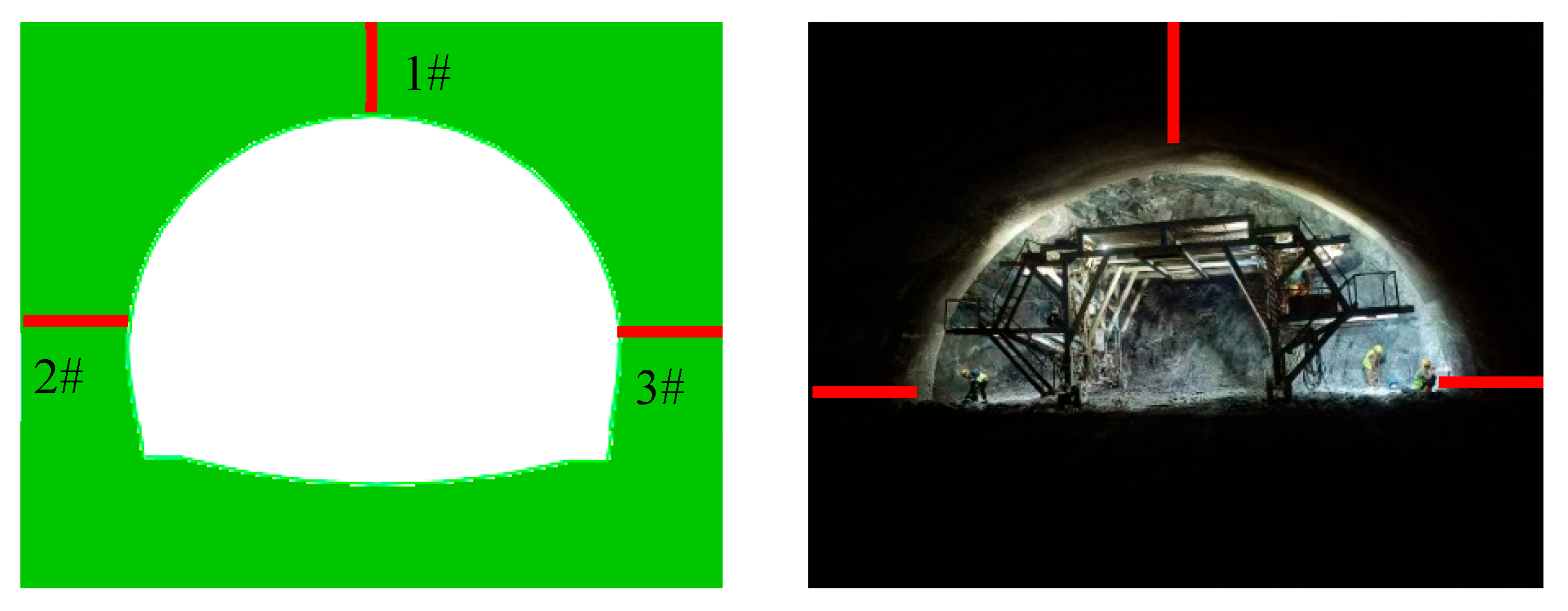
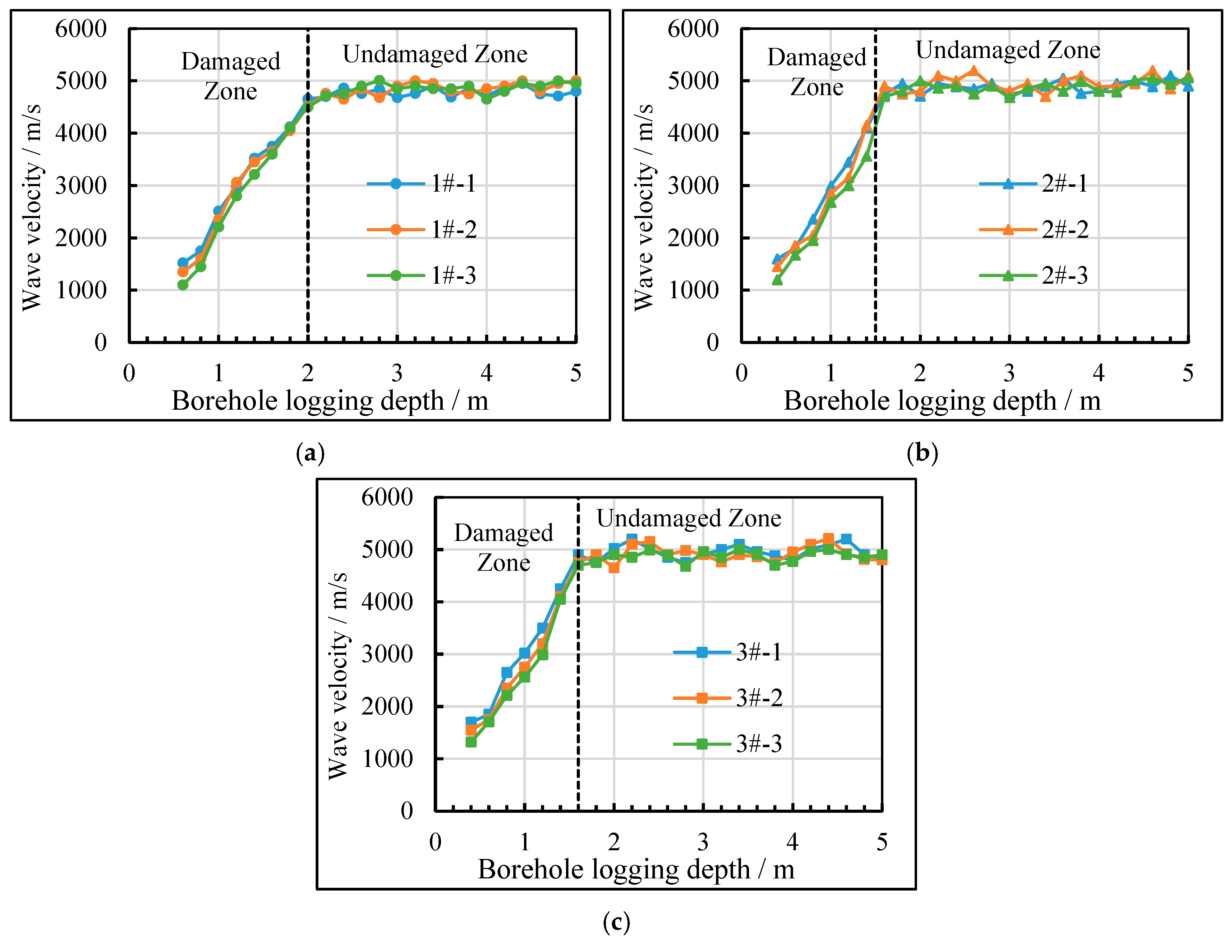
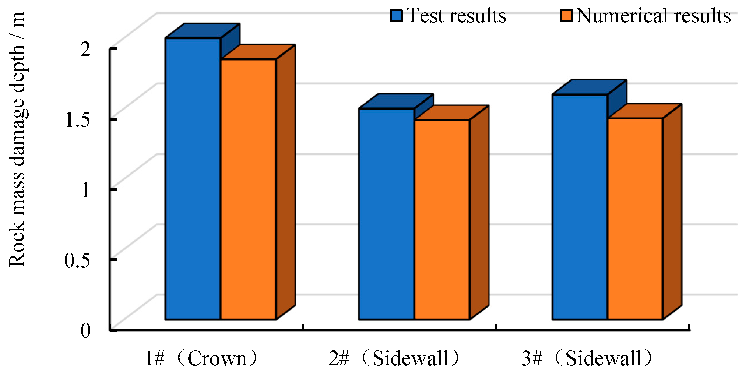
5. In Situ Testing and Analysis

Considering the actual on-site construction conditions, tests were conducted to assess the surrounding rock damage caused by blasting load during the construction of the ramp tunnel for this project. A cross-section at ZB2K0+60 of the ramp tunnel was selected, and three measurement holes were arranged at the vault and both sidewalls for on-site acoustic wave testing. The layout of the measurement holes is shown in Figure 18. Acoustic wave testing was conducted after each excavation blasting, with three measurements taken per borehole. The wave velocity results for each monitoring point are presented in Figure 19. The damage depth of the surrounding rock in the ramp tunnel was obtained through the testing. A comparison between the on-site test results and the numerical calculation results for the damage depth of the surrounding rock in the ramp tunnel is presented in Table 3 and Figure 20.
As can be seen from Table 3 and Figure 20, the damage depth measured in the ramp tunnel is greater at the vault, with a depth range of approximately 2.00 m, while the damage depth at the sidewalls is slightly smaller, ranging from about 1.50 to 1.60 m. The numerical calculation results indicate that the damage depth of the surrounding rock is 1.85 m at the vault and 1.42 to 1.43 m at the sidewalls. Compared to the measured depths, the numerical results show a reduction of 7.5% at the vault and 5.3% to 10.6% at the sidewalls. The test results are largely consistent with the numerical calculation results, which also demonstrates the rationality and feasibility of the numerical calculations for the abovementioned construction scheme.

6. Conclusions

Based on the Tashan North Road Expressway Tunnel Project, the damage to surrounding rock under cyclic blasting construction in bifurcated small-spacing tunnels was studied using numerical simulation and field testing. By comprehensively considering the combined effects of in situ stress and blasting loads, the damage characteristics of the intermediate rock wall in bifurcated tunnels under different construction schemes were analyzed and discussed, along with the main influencing factors of intermediate rock wall damage. The following conclusions were drawn:
  • The damage to the surrounding rock of the bifurcated tunnel caused by blasting construction is mainly concentrated on the side of the intermediate rock wall. The damage zone gradually decreases from the excavation contour surface toward the center of the intermediate rock wall thickness, exhibiting an asymmetric “U”-shaped distribution. At the haunch and sidewall sections of the intermediate rock wall, the damage to the surrounding rock is greater on the side closer to the trailing tunnel. In contrast, at the springing section, the damage is more significant on the side closer to the leading tunnel. Along the height direction of the intermediate rock wall, the damage is more pronounced at the sidewall section, followed by the springing section and the haunch section. Along the tunnel axis direction, the closer the location is to the starting position of the bifurcated tunnel, the thinner the intermediate rock wall and the greater the damage to the surrounding rock. Within a range of 5 m from the starting position of the bifurcated tunnel, the damaged zones of the intermediate rock wall are interconnected, necessitating safety measures during construction. For tunnel construction within 10 m of the bifurcation starting point, pre-grouting (e.g., pipe roof grouting) and radial bolt reinforcement in the intermediate rock wall are recommended to enhance its integrity and strength.
  • During the blasting construction process, the construction of the trailing main-line tunnel significantly impacts the damage to the intermediate rock wall. The damage to the surrounding rock is relatively minor after the excavation of the upper bench of the leading ramp tunnel but increases after the excavation of the lower bench. The damage to the intermediate rock wall significantly increases after the construction of the trailing main-line tunnel, especially following the excavation of its lower bench. During each excavation step of the ramp and main-line tunnels, the damage to the intermediate rock wall is primarily caused by the blasting load. As tunnel excavation progresses, the damage to the rock wall gradually increases under the combined effects of the blasting load and the excavation-induced space effects. During tunnel excavation, immediate protection measures should be implemented for the intermediate rock wall after its formation, including the prompt installation of initial support near the rock wall excavation faces to minimize exposure time.
  • During the construction of bifurcated tunnels, the smaller the offset distance between the leading and trailing tunnel faces is, the earlier the intermediate rock wall forms, and the greater the damage to the surrounding rock. As the offset distance between the leading and trailing tunnel faces increases, the damage to the intermediate rock wall gradually decreases. Constructing the tunnel with a larger cross-sectional area first will cause more damage to the intermediate rock wall. Therefore, it is safer and more rational to construct the tunnel with a smaller cross-sectional area first. When using the bench method, the damage to the intermediate rock wall decreases as the bench length increases. Thus, the bench length should be increased as much as possible to ensure the safety of the rock wall. When in situ conditions permit, priority should be given to constructing the ramp tunnel first, with a bench length maintained at 8 m and a face offset distance exceeding 16 m.
  • These research findings provide a valuable reference for determining a safe and rational blasting schemes for this bifurcated small-spacing tunnel. However, it should be noted that the numerical simulation of construction schemes assumes homogeneous and isotropic material properties for the surrounding rock vibration-damage analysis, while insufficiently accounting for practical engineering factors such as geological discontinuities, delayed blasting, and actual blast hole arrangements. These aspects warrant further investigation in subsequent research.

Author Contributions

Conceptualization, M.S.; Data curation, Y.W. and G.D.; Formal analysis, M.S. and K.S.; Funding acquisition, Y.W. and G.D.; Investigation, M.S., K.S. and Y.W.; Methodology, M.S., K.S.; Resources, M.S., Y.W. and G.D.; Supervision, K.S., X.X. and K.Y.; Validation, M.S., Y.W., G.D., and K.S.; Visualization, M.S., X.X. and K.Y.; Writing—original draft, M.S. and Y.W.; Writing—review and editing, M.S., G.D. and K.S. All authors have read and agreed to the published version of the manuscript.

Funding

This research received no external funding.

Data Availability Statement

The original contributions presented in this study are included in the article. Further inquiries can be directed to the corresponding author.

Conflicts of Interest

Authors Yantao Wang, Guangwei Dai, Xuyang Xie and Kejia Yu were employed by the company China Construction Third Engineering Bureau Urban Construction Co., Ltd. The remaining authors declare that the research was conducted in the absence of any commercial or financial relationships that could be construed as a potential conflict of interest.

References

  1. Zhang, Y.W.; Zhang, Y.D.; Song, Z.P.; Pan, H.W. A LFPP-FAHP based evaluation model of blasting scheme for tunnel undercrossing existing buildings. Tunn. Undergr. Space Technol. 2024, 153, 105937. [Google Scholar] [CrossRef]
  2. Wang, F.; Xue, Y.H.; Zhang, Y.Y.; Pan, Y.D.; Luo, C. Response of existing lining subjected to closed blasting in zero-spacing twin tunnels and its damping measures. Eng. Fail. Anal. 2024, 166, 108847. [Google Scholar] [CrossRef]
  3. Wang, X.; Li, J.C.; Zhao, X.B.; Liang, Y. Propagation characteristics and prediction of blast-induced vibration on closely spaced rock tunnels. Tunn. Undergr. Space Technol. 2023, 123, 104416. [Google Scholar] [CrossRef]
  4. He, B.; Armaghani, D.J.; Lai, S.H.; He, X.Z.; Asteris, P.G.; Sheng, D.C. A deep dive into tunnel blasting studies between 2000 and 2023-Asystematic review. Tunn. Undergr. Space Technol. 2024, 147, 105727. [Google Scholar] [CrossRef]
  5. Guan, X.M.; Xu, H.W.; Fu, H.X.; Zhang, W.J.; Li, P.F.; Ding, H.; Yu, K.; Zhang, S.L. Vibration characteristics, attenuation law and prediction method in the near field of tunnel blasting. Case Stud. Constr. Mater. 2023, 19, e02662. [Google Scholar] [CrossRef]
  6. Guan, X.M.; Yao, Y.K.; Yang, N.; Xu, H.W.; Xin, B.C.; Li, B.Y. Analysis of factors influencing vibration reduction and design optimization of damping holes in adjacent tunnel blasting. Case Stud. Constr. Mater. 2023, 19, e02448. [Google Scholar] [CrossRef]
  7. Wang, X.; Hou, X.F.; Yuan, W.; He, C.D.; Sarfarazi, V.S.; Fan, H. Attenuation of blast-induced vibration on tunnel structures. Geohazard Mech. 2024, 2, 153–163. [Google Scholar] [CrossRef]
  8. Xu, M.N.; Li, X.P.; Xu, K.; Liu, T.T.; Zhang, Y.; Yang, T. Influence of the spatial distribution of underground tunnel group on its blasting vibration response. Undergr. Space 2023, 10, 248–268. [Google Scholar] [CrossRef]
  9. Lu, W.B.; Yang, J.H.; Yan, P.; Chen, M.; Zhou, C.B.; Luo, Y.; Jin, L. Dynamic response of rock mass induced by the transient release of in-situ stress. Int. J. Rock Mech. Min. Sci. 2012, 53, 129–141. [Google Scholar] [CrossRef]
  10. Xu, S.X.; Wu, B.; Zhang, H.L.; Qi, S.X.; Bian, H.B.; Wang, J.J. Directional crack propagation and optimization strategies for multi-hole shaped charge blasting in tunnel construction. Structures 2025, 72, 108268. [Google Scholar] [CrossRef]
  11. Ding, J.J.; Yang, J.H.; Ye, Z.W.; Leng, Z.D.; Zhou, C.B. Numerical study on rock blasting assisted by in-situ stress redistribution. Tunn. Undergr. Space Technol. 2024, 153, 106022. [Google Scholar] [CrossRef]
  12. Li, X.D.; Liu, K.W.; Sha, Y.Y.; Yang, J.C.; Hong, Z.X. Experimental and numerical investigation on rock fracturing in tunnel contour blasting under initial stress. Int. J. Impact Eng. 2024, 185, 104844. [Google Scholar] [CrossRef]
  13. Yan, P.; Lu, W.B.; Chen, M.; Hu, Y.G.; Zhou, C.B.; Wu, X.X. Contributions of in-situ stress transient redistribution to blasting excavation damage zone of deep tunnels. Rock Mech. Rock Eng. 2015, 48, 715–726. [Google Scholar] [CrossRef]
  14. Chen, M.; Lu, W.B.; Yan, P.; Hu, Y.G. Blasting Excavation induced damage of surrounding rock masses in deep-buried tunnels. KSCE J. Civ. Eng. 2016, 20, 933–942. [Google Scholar] [CrossRef]
  15. Verma, H.K.; Samadhiya, N.K.; Singh, M.; Goel, R.K.; Singh, P.K. Blast induced rock mass damage around tunnels. Tunn. Undergr. Space Technol. 2018, 71, 149–158. [Google Scholar] [CrossRef]
  16. Li, Q.; Li, H.B.; Fu, S.Y.; Li, X.F. The effect of in-situ stress on blast-induced rock fracture and damage zone. Tunn. Undergr. Space Technol. 2024, 154, 106091. [Google Scholar] [CrossRef]
  17. Wang, Y.Q.; Chen, Y.Q.; Li, C.H.; He, Y.S.; Wang, Q.R.; Xu, J.M.; Fan, J.Q.; Dai, M.N. Model test study on the dynamic failure process of tunnel surrounding rocks in jointed rock mass under explosive load. Eng. Fail. Anal. 2025, 167, 108996. [Google Scholar] [CrossRef]
  18. Ji, L.; Zhou, C.B.; Lu, S.W.; Jiang, N.; Li, H.B. Modeling study of cumulative damage effects and safety criterion of surrounding rock under multiple full-face blasting of a large cross-section tunnel. Int. J. Rock Mech. Min. Sci. 2021, 147, 104882. [Google Scholar] [CrossRef]
  19. Li, Z.; Hu, Y.; Wang, G.Z.; Zhou, M.; Hu, W.J.; Zhang, X.J.; Gao, W.X. Study on cyclic blasting failure characteristics and cumulative damage evolution law of tunnel rock mass under initial in-situ stress. Eng. Fail. Anal. 2023, 150, 107310. [Google Scholar] [CrossRef]
  20. Zhao, R.; Tao, M.; Karakus, M. Damage zone around underground opening caused by combined blast loading and initial stress unloading. Int. J. Rock Mech. Min. Sci. 2025, 186, 106018. [Google Scholar] [CrossRef]
  21. Zhu, Y.M.; Tang, Y.L.; Wang, H.C.; Zhang, Q.B. Development of a dynamic cumulative damage model and its application to underground hydropower caverns under multiple blasting. Int. J. Rock Mech. Min. Sci. 2024, 184, 105948. [Google Scholar] [CrossRef]
  22. Fu, S.Y.; Li, H.B.; Liu, L.W.; Li, Q.; Li, X.F. Study on the characteristics of blast-induced damage zone by using the wave velocity field inversion technique. Comput. Geotech. 2024, 176, 106808. [Google Scholar] [CrossRef]
  23. Wang, Q.R.; Xie, L.X.; Song, E.X.; Kong, F.L.; Fan, J.Q.; Yu, L.Y.; Xu, J.M.; Shi, X.Y. Model tests on dynamic responses of surrounding rock and support structure on underground tunnel under combined dynamic and static loading. Int. J. Rock Mech. Min. Sci. 2023, 171, 105572. [Google Scholar] [CrossRef]
  24. Song, Z.G.; Zou, S.M.; Zhou, W.X.; Huang, Y.; Shao, L.W.; Yuan, J. Clinically applicable histopathological diagnosis system for gastric cancer detection using deep learning. Nat. Commun. 2020, 11, 4294. [Google Scholar] [CrossRef]
  25. Kabir, H.; Wu, J.; Dahal, S.; Joo, T.; Garg, N. Automated estimation of cementitious sorptivity via computer vision. Nat. Commun. 2024, 15, 9935. [Google Scholar] [CrossRef]
  26. Wu, X.D.; Gong, M.; Wu, H.J.; Hu, G.F.; Wang, S.J. Vibration reduction technology and the mechanisms of surrounding rock damage from blasting in neighborhood tunnels with small clearance. Int. J. Min. Sci. Technol. 2023, 33, 625–637. [Google Scholar] [CrossRef]
  27. Ling, T.L.; Li, S.L.; Liu, D.S.; Liang, S.F. Blasting damage of tunnel rock mass based on cumulative effect. Rock Mech. Rock Eng. 2023, 56, 1679–1695. [Google Scholar] [CrossRef]
  28. Yang, H.P.; Yu, J.; Fu, X.Q.; Yao, W.; Lin, C.B.; Chang, F.Q. Damage characteristics of intercalary rock in bifurcated tunnel under alternate blasting excavation. J. Vib. Shock 2023, 42, 46–53. [Google Scholar] [CrossRef]
  29. Li, H.B.; Xiang, X.; Li, J.C.; Zhao, J.; Liu, B.; Liu, Y.Q. Rock damage control in bedrock blasting excavation for a nuclear power plant. Int. J. Rock Mech. Min. Sci. 2011, 48, 210–218. [Google Scholar] [CrossRef]
  30. Guan, X.M.; Yang, N.; Zhang, W.J.; Li, M.G.; Liu, Z.L.; Wang, X.H.; Zhang, S.L. Vibration response and failure modes analysis of the temporary support structure under blasting excavation of tunnels. Eng. Fail. Anal. 2022, 136, 106188. [Google Scholar] [CrossRef]
  31. Cho, S.H.; Kaneko, K. Influence of the applied pressure waveform on the dynamic fracture processes in rock. Int. J. Rock Mech. Min. Sci. 2004, 41, 771–784. [Google Scholar] [CrossRef]
  32. Hu, Y.G.; Lu, W.B.; Jin, X.H.; Chen, M.; Yan, P. Numerical simulation for excavation blasting dynamic damage of rock high slope. Chin. J. Rock Mech. Eng. 2012, 31, 2204–2213. [Google Scholar]
  33. Shin, J.H.; Moon, H.G.; Chae, S.E. Effect of blast-induced vibration on existing tunnels in soft rocks. Tunn. Undergr. Space Technol. 2011, 26, 51–56. [Google Scholar] [CrossRef]
  34. Sun, P.C.; Yang, G.D.; Lu, W.B.; Fan, Y.; Meng, H.L.; Xue, L. A study on explosion load history of rock blasting considering rock failure zones. Explos. Shock Waves 2024, 44, 171–186. [Google Scholar] [CrossRef]
  35. Jiang, N.; Lyu, G.P.; Wu, T.Y.; Zhou, C.B.; Li, H.B.; Yang, F. Vibration effect and ocean environmental impact of blasting excavation in a subsea tunnel. Tunn. Undergr. Space Technol. 2023, 131, 104855. [Google Scholar] [CrossRef]
  36. Deng, J. Analytical and numerical investigations on pillar rockbursts induced by triangular blasting waves. Int. J. Rock Mech. Min. Sci. 2021, 138, 104518. [Google Scholar] [CrossRef]
  37. Henrych, J. The Dynamics of Explosion and Its Use: Developments in Civil Engineering; Elsevier: Amsterdam, The Netherlands, 1979; pp. 59–64. [Google Scholar]
  38. Esen, S.; Onederra, I.; Bilgin, H.A. Modelling the size of the crushed zone around a blasthole. Int. J. Rock Mech. Min. Sci. 2003, 40, 485–495. [Google Scholar] [CrossRef]
  39. Luo, S.; Yan, P.; Lu, W.B.; Chen, M.; Wang, G.H. Research on the simulation of blasting damage and its mechanism of deep tunnel excavation. Chin. J. Rock Mech. Eng. 2021, 40 (Suppl. S1), 2760–2772. [Google Scholar]
Figure 1. Plan and cross-section diagrams of the bifurcated tunnel.
Buildings 15 02737 g001
Figure 2. Geological profile of the bifurcated tunnel section.
Buildings 15 02737 g002
Figure 3. Time history curve of triangular blasting load.
Buildings 15 02737 g003
Figure 4. The numerical calculation model of bifurcated tunnels. (a) Overall model. (b) Local model. (c) Initial support.
Buildings 15 02737 g004
Figure 5. Equivalent load acting on the excavation contour surface of the tunnel.
Buildings 15 02737 g005
Figure 6. Damage distribution diagrams of the surrounding rock at each observation cross-section of the bifurcated tunnel.
Buildings 15 02737 g006
Figure 7. Damage variation curves of the intermediate rock wall in the longitudinal section of the bifurcated tunnel. (a) Upper section (haunch). (b) Central section (side wall). (c) Lower section (springing).
Buildings 15 02737 g007
Figure 8. Damage variation diagram at the central position of the thickness of the intermediate rock wall in the bifurcated tunnel.
Buildings 15 02737 g008
Figure 9. Damage distribution curves of Path B in the middle section of the rock wall during the construction process. (a) Excavation of the upper bench of the ramp tunnel. (b) Excavation of the lower bench of the ramp tunnel. (c) Excavation of the upper bench of the main-line tunnel. (d) Excavation of the lower bench of the main-line tunnel.
Buildings 15 02737 g009
Figure 10. Damage distribution curves of the rock wall during the construction process of the bifurcated tunnel.
Buildings 15 02737 g010
Figure 11. Damage depths of the surrounding rock on both sides of the ramp and main-line tunnels. (a) Surrounding rock on the left side of the ramp tunnel. (b) Surrounding rock on the right side of the main-line tunnel.
Buildings 15 02737 g011
Figure 12. Damage curves of the middle section of the intermediate rock wall in the bifurcated tunnel. (a) Path B. (b) Path C.
Buildings 15 02737 g012
Figure 13. Comparison of the damage at the central position of the thickness of the intermediate rock wall in the bifurcated tunnel.
Buildings 15 02737 g013
Figure 14. Damage curves of the intermediate rock wall at Section B in the bifurcated tunnel under different construction sequences. R represents that the ramp tunnel is constructed first; M represents that the main-line tunnel is constructed first.
Buildings 15 02737 g014
Figure 15. Comparison of the damage depths of the surrounding rock at Section B in the bifurcated tunnel under different construction sequences. (a) Ramp tunnel. (b) Main-line tunnel.
Buildings 15 02737 g015
Figure 16. Damage curves of the middle section of the rock wall in the bifurcated tunnel under different construction bench lengths.
Buildings 15 02737 g016
Figure 17. Comparison of the damage at the central position of the thickness of the intermediate rock wall in the bifurcated tunnel under different construction bench lengths.
Buildings 15 02737 g017
Figure 18. Layout diagram of measuring holes for the damage of the surrounding rock in the ramp tunnel.
Buildings 15 02737 g018
Figure 19. Test results of acoustic wave velocities in surrounding rock of the ramp tunnel. (a) 1#. (b) 2#. (c) 3#.
Buildings 15 02737 g019
Figure 20. Comparison between the test results and the numerical calculation results of the damage depth of the surrounding rock in the ramp tunnel.
Buildings 15 02737 g020
Table 1. Tunnel construction schemes for numerical calculation.
Influencing FactorsRamp TunnelMain-Line Tunnel
Offset distance of working faces4 m, 8 m, 12 m, 16 m-
Construction sequence Ramp tunnel excavated firstMain-line tunnel excavated first
Bench length-4 m, 8 m
Table 2. Calculation parameters of surrounding rock and support structures.
ItemsDensity ρ (kg/m3)Elastic Modulus
E (GPa)
Poisson’s Ratio
μ
Cohesion
c (kPa)
Internal Friction Angle
φ (°)
Tensile Strength
(MPa)
Compressive Strength
(MPa)
Materials
Rock245050.3280 kpa382.580
Support265022.50.25----
Table 3. Comparison of the results of the damage depth of the surrounding rock in the ramp tunnel.
Test HolesTest ResultsNumerical
Calculation Results
1#2.001.85
2#1.501.42
3#1.601.43
Disclaimer/Publisher’s Note: The statements, opinions and data contained in all publications are solely those of the individual author(s) and contributor(s) and not of MDPI and/or the editor(s). MDPI and/or the editor(s) disclaim responsibility for any injury to people or property resulting from any ideas, methods, instructions or products referred to in the content.

