Article

Elastic Critical Buckling Coefficients for Skew Plates of Steel Structures under Biaxial Normal Stress

Department of Architecture and Building Engineering, Tokyo Institute of Technology, Tokyo 152-8550, Japan
*
Author to whom correspondence should be addressed.
Buildings 2024, 14(4), 901; https://doi.org/10.3390/buildings14040901
Submission received: 13 February 2024 / Revised: 20 March 2024 / Accepted: 25 March 2024 / Published: 26 March 2024

Abstract

:
In steel structures, skew thin steel plates serve as panel zones in structures spanning large spaces (e.g., warehouses and gymnasiums). Considerable research has been conducted on the shear buckling of panels due to seismic loads acting on a structure. Conversely, under snow or wind loads, the panel zone may experience compressive and tensile stresses simultaneously from two directions. Considering the economic preference for thin steel plates, evaluating the elastic critical local buckling stresses in the panel zone under biaxial normal stress may provide essential information to structural engineers. In this study, an elastic buckling analysis based on the energy method is performed to clarify the impact of panel geometry and boundary conditions on the elastic local buckling stresses of skew panel zones. As confirmed from the results, the local buckling stresses calculated using the energy method were consistent with those determined using finite element analysis. The findings indicate that a skew angle of up to 30° marginally affects the elastic buckling stress under uniaxial stress. Consequently, engineer-friendly design formulas were developed based on these findings. Comparisons with previous research demonstrated that the buckling loads reported were generally higher than those determined by finite element analysis. The study also established the correlation of the buckling stresses under biaxial stresses, which implied that the skew angle posed minimal influence on buckling stress for skew plates under biaxial stress. Additionally, a method for evaluating this correlation was presented. Engineers can utilize the provided design equations to more efficiently and accurately calculate buckling loads, facilitating a safer and more economical design of structures with skew plates.

1. Introduction

Parallelogram-shaped (skew-shaped) thin steel plates are frequently integrated into diverse structures such as swept-wing aircraft, ships, and bridge plate girders. In structural steel buildings, skew thin steel plates function as panel zones within structures encompassing large spaces, such as warehouses and gymnasiums, contingent on a roof slope of approximately 30° [1], as illustrated in Figure 1. When a horizontal load, such as an earthquake load, acts on a structure, the moment acting on the column is transferred to the beam through the panel zone; consequently, the stress acting on the panel zone is dominated by shear stress [1,2]. Therefore, several studies have investigated the effect of shear stress on shear buckling in the panel zone.
For instance, Wittrick [3,4] derived a determinantal equation for calculating the elastic critical buckling load for skew plates under uniform shear using a unique coordinate system proposed by Iguchi [5], revealing that the elastic buckling load varies with the direction of shear stress. Cook et al. [6,7] explored the critical shear buckling load of infinitely long plate elements with intermediate transverse stiffeners and clamped edges, presenting comparisons between theoretical and experimental results. Ikarashi et al. [8,9] developed a design formula for the critical elastic shear buckling load of panel zones in L-shaped connections using the energy method alongside a method for predicting the ultimate load of the panel zone. Mitsui et al. [10] formulated design equations for the elastic shear buckling load of skew plates under uniformly distributed shear stresses using the energy method, demonstrating that these equations accurately evaluate the elastic buckling loads without necessitating complex computations.
In contrast, under snow or wind loads, the panel zone may be subjected to both compressive and tensile stresses simultaneously from two directions. Given the recent trend toward utilizing thinner steel plates for economic advantages, assessing the elastic critical local buckling stress in the panel zone under biaxial normal stresses is imperative for providing essential design information to structural engineers. Nonetheless, the elastic critical local buckling stress of skew plates, even under the basic stress state of uniform compressive stresses, remains poorly understood, in stark contrast to the well-explored domain of elastic critical local buckling issues of rectangular shapes. Clarifying this discrepancy is vital for a comprehensive understanding of the behavior of skew plates under compressive stress.
The energy method is a promising theoretical approach for determining the local buckling loads of flat plates. Research on the critical local buckling load of rectangular plates employing the energy method has been conducted. Timoshenko [11] provided an analysis of the elastic critical buckling stress of simply supported rectangular plates under uniform normal stresses using this method. In his study, Timoshenko considered not only uniaxial stress but also biaxial normal stresses, presenting correlated functions for rectangular plates under simply supported conditions subjected to biaxial stresses.
Araghi et al. [12] introduced interaction curves and a methodology for predicting the post-buckling behavior of orthotropic rectangular plates under biaxial stresses, utilizing an energy method for precise buckling load predictions. Wang et al. [13] developed a differential quadrature method to solve the elastic local buckling load of rectangular plates under biaxial compressive point loads. The stress distribution in a plate element subjected to a point load is nonuniform, making it difficult to accurately determine its buckling load. However, the method presented by Wang et al. can accurately reproduce the stress distribution and calculate the buckling load, even when the boundary conditions are varied.
Research on the local buckling of skew plates has also utilized the energy method for addressing local instability issues. Wittrick [14] investigated the elastic local buckling stress of clamped-supported skew plates under uniform compression along longitudinal edges, offering an early solution to the buckling problem of skew plates with a formula for uniaxial compression-induced local buckling stress. Durvasula [15] explored buckling stresses of simply supported skew plates under uniaxial compression, employing the Rayleigh-Ritz method to formulate a matrix equation for computing buckling coefficients and providing charts for these coefficients under uniform compressive and shear stresses.
Kennedy et al. [16] applied an energy method to assess the elastic local buckling stress in simply supported orthotropic and isotropic skew plates under uniaxial compressive forces, demonstrating that an increase in the skew angle elevates the buckling stress and offering a chart for engineering design applications. Mizusawa et al. [17,18] examined the buckling stress of skew plates with mixed boundary conditions through the spline element method, noting an increase in elastic local buckling stress with the skew angle. Yoshimura et al. [19] investigated the influence of the skew angle on the elastic local buckling loads under the uniaxial uniform compression of skew plates with simply supported edges through the energy method. Ashton [20] analyzed the elastic local buckling load of clamped skew plates under combined loads using the energy method; however, the skew angle and aspect ratio were constrained, yielding limited practical research outcomes. Mishra et al. [21] developed a determinant equation for the elastic buckling load of laminated composite skew plates under uniaxial compressive stress but did not present simple design formulas for practical application. Despite numerous studies on the local buckling load of skew plates, few have theoretically examined these loads under biaxial stresses. Moreover, a straightforward design equation for quantitatively evaluating the elastic local buckling stress under uniaxial compression without necessitating complex calculations has yet to be introduced.
To address this issue, the current study endeavors to clarify the impacts of panel geometry, boundary conditions, and load conditions on the elastic local buckling stresses of skew panel zones, as depicted in Figure 2, through an elastic buckling analysis utilizing the energy method. Section 2 introduces a distinctive displacement function that replicates local buckling deformation under uniform uniaxial and biaxial normal stresses alongside a description of an energy method informed by Timoshenko’s plate buckling theory [11]. The energy method calculates the strain energy and the work done by uniform uniaxial and biaxial normal stresses for an assumed deflected shape, where the accuracy of the assumed shape is crucial for determining critical buckling loads. In Section 3, the study examines the influence of the skew shape and boundary conditions on the elastic local buckling coefficient, specifically for scenarios where the normal stress, as shown in Figure 2, independently impacts the skew plate.
The buckling stresses estimated by the energy method accurately simulated the local buckling stresses, displaying comparable precision to finite element analysis (FEA). The findings demonstrated that a skew angle of up to 30° exerts a negligible influence on the elastic buckling stress under uniaxial stress. These insights led to the development of engineer-friendly design formulas. Moreover, when comparing the buckling loads reported in prior research with FEA results, it was observed that previously reported buckling loads were relatively higher than those determined by FEA.
Because design equations for the buckling coefficient of skew plates subjected to uniaxial stress have not been presented in prior research, this study proposes design equations derived from theoretical analysis results. These proposed design equations can provide substantial value to engineers, offering a precise and straightforward method for predicting the complex phenomenon of local buckling in skew plates. In Section 4, the study extends to explore biaxial normal stresses, presenting correlation curves for each boundary condition. This provides structural engineers with essential reference data for designing steel structures, including panel zones of moment frames under biaxial stress as well as plate girders of bridges subjected to distributed vertical loads and axial forces in the horizontal direction.

2. Elastic Local Buckling of Skew Plates under Uniform Uniaxial Normal Stress

2.1. Outline of Theoretical Analysis Modeling

Utilizing an energy method grounded in Timoshenko’s plate buckling theory [11], this study investigated the elastic local buckling stress of a skew plate under an ideal uniaxial uniform normal stress. The theoretical analysis model and the coordinate system, outlined in Figure 2, employed a Cartesian coordinate system for straightforward stress management. The theoretical model, illustrated in Figure 2b, represents a skew plate, with the panel zone in the moment frame depicted in Figure 2a rotated by 90° to align with theoretical models from previous studies. The dimensions of the theoretical model include length a, height b, and a uniform thickness t, with θ indicating the skew angle.
This study considered skew angles ranging from 0° to 30° to reflect practical applications. σcr,x represents the critical normal stress acting parallel to the longitudinal direction, and σcr,y signifies the critical normal stress acting perpendicular to the longitudinal direction. The boundary conditions were defined as simply clamped supported for all four edges.
The displacement function w, utilized in the theoretical model, aligns with the method previously employed by the authors for determining the buckling coefficients of skew plates under uniform shear stress [10]. The displacement function w for simply supported skew plates is expressed by Equation (1).
w = m = 1 M n = 1 N a m n sin m π x + y tan θ a sin n π y b .
Displacement function w for clamped-supported skew plates is expressed as Equation (2).
w = m = 1 M n = 1 N a m n sin π x + y tan θ a sin m π x + y tan θ a sin π y b sin n π y b ,
where m and n are natural numbers representing the number of terms in the series and represent the number of half-wavelengths in the parallel and perpendicular directions, respectively. amn is an undetermined coefficient. Both displacement functions w for the skew plates were expressed using a Fourier series and satisfied the boundary conditions on the edges. The out-of-plane displacements of all the edges of the skew plate defined by both displacement functions were zero (w = 0). Since the simply supported edges are allowed to rotate, the displacement function (1) is defined so that it can express the rotation of simply supported edges (∂w/∂x ≠ 0, ∂w/∂y ≠ 0). Conversely, displacement function (2) is defined so that it can express the non-rotation of clamped-supported edges (∂w/∂x = 0, ∂w/∂y = 0).

2.2. Outline of Theoretical Analysis Modeling

According to Timoshenko’s plate buckling theory [11], the strain energy of a skew plate ΔU can be expressed as follows:
U = D 2 A   2 w x 2 2 + 2 w y 2 2 + 2 ν 2 w x 2 2 w y 2 + 2 1 ν 2 w x y 2 d x d y ,
where A is the integral range enclosed by the plate, and D denotes the flexural rigidity of the plate and can be expressed as
D = E t 3 12 1 ν 2 ,
where E denotes the Young’s modulus and ν denotes the Poisson’s ratio. As shown in Figure 2b, the works ΔTx, ΔTy done by uniform normal stresses parallel and perpendicular to the longitudinal edges can be written as follows, respectively.
T x = σ c r , x t 2 A   w x 2 d x d y = k x σ 0 t 2 A   w x 2 d x d y ,
T y = σ c r , y t 2 A   w y 2 d x d y = k y σ 0 t 2 A   w y 2 d x d y ,
σ 0 = π 2 E t 2 12 1 ν 2 b 2 .
Here, kx, ky are the buckling coefficients, respectively, and σ0 is defined as the base stress in this study. Assuming that the strain energy is equal to the work done by the uniform normal stress parallel to the longitudinal edges, the potential energy Πx obtained by performing an integral calculation can be expressed as follows:
Π x = U + T x = 0 .
Based on the principle of minimum potential energy, the buckling condition Equation (9) can be obtained by differentiating Equation (8) with respect to the auxiliary variable amn as follows:
Π x a m n = U + k x σ 0 · T x 0 a m n = 0                 m = 1 ,   2 , 3 ,   ,   M ;   n = 1 ,   2 , 3 ,   , N ,
a m n T = a 11 a 12 a 1 N a 21 a M 1 a M 2 a M N .
Equation (10) was used to simplify the expression for the buckling condition in Equation (9). The following buckling conditions can be obtained by differentiating Equation (8) using all auxiliary variables amn and formulating a system of linear equations:
U + k x σ 0 T a m n = 0 ,
c m n T = a 11 a 12 a 1 N a 21 a M 1 a M 2 a M N ,
where U denotes a matrix composed of Equation (3), T indicates a matrix composed of Equation (5), and {amn} represents a coefficient matrix expressed by Equation (12). The elastic local buckling stress parallel to the longitudinal direction σcr,x = kxσ0 can be obtained by determining the lowest eigenvalues when Equation (11) has nontrivial solutions, i.e., when {amn} in Equation (11) has a non-{0} solution. Equations (8)–(11) detail the elastic local buckling stress induced by normal stress parallel to the longitudinal direction, whereas the elastic local buckling stress owing to normal stress perpendicular to the longitudinal direction was ascertained using an analogous procedure. The buckling displacements corresponding to the elastic local buckling stresses in each direction were identified as eigenvectors associated with the eigenvalues.

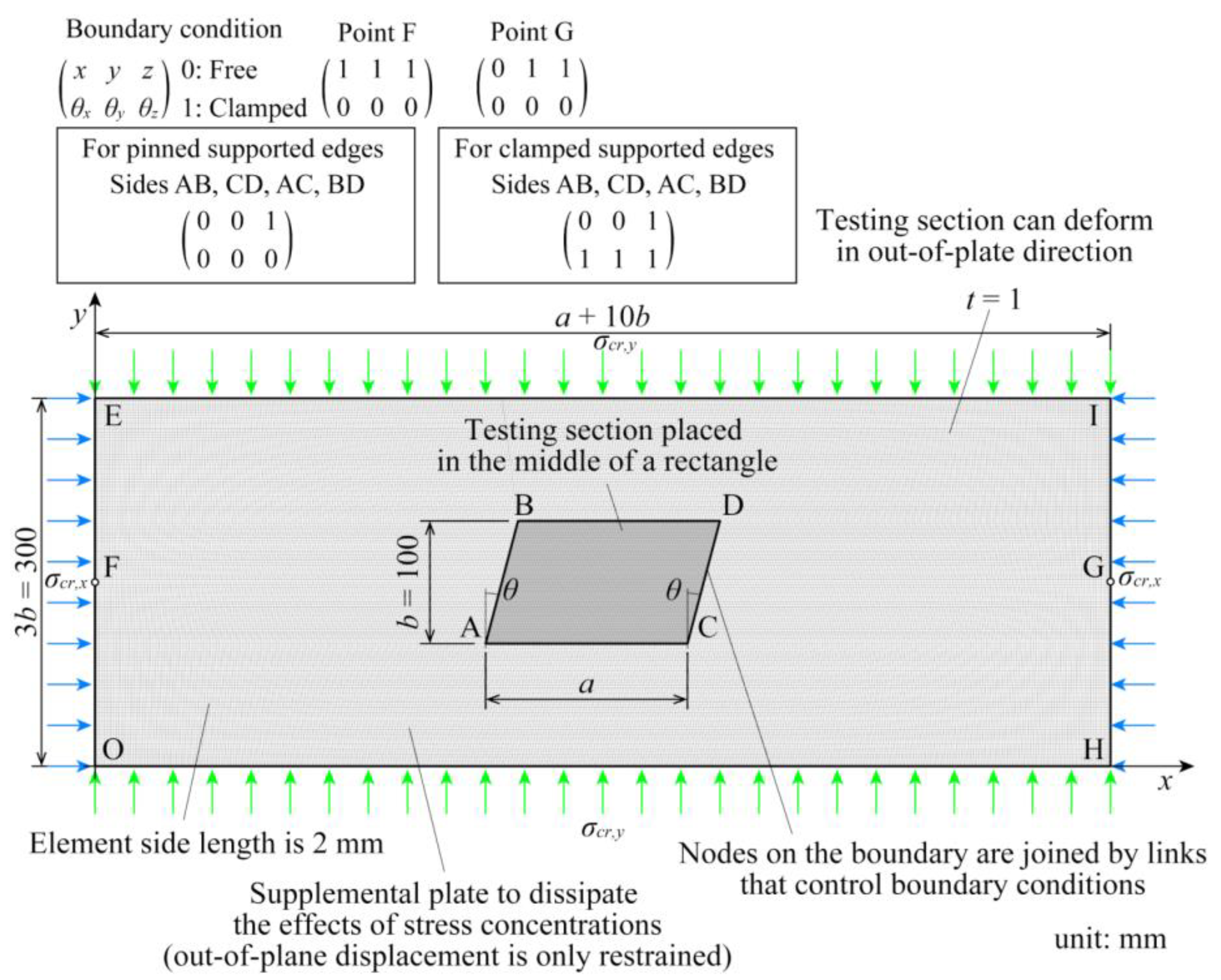
2.3. Finite Element Model for Validation of Energy Methods

A buckling eigenvalue analysis conducted using FEM accurately identified the elastic local buckling loads for skew plates under compressive stresses. This analysis was conducted using FEM to validate the outcomes of the eigenvalue analysis based on the energy method detailed in the preceding section.
The finite element (FE) software MSC Marc version 2022 [22,23] was utilized to develop a numerical model of the skew plates, as illustrated in Figure 3. This model utilized Element 139 [22], a four-node, thin-shell element with capabilities for analyzing both curved shell and complex plate structures. Element 139 features global displacements and rotations as degrees of freedom, and it can be used in curved shell analysis as well as in the analysis of complicated plate structures. Based on the mesh size and buckling load considerations displayed in Figure 4, a mesh size of 2 × 2 mm was selected, guided by a convergence study, to ensure precision. Regarding material properties, the Young’s modulus and Poisson’s ratio were set to 205 GPa and 0.3, respectively. The FE model had a rectangular shape and was composed of a testing section and auxiliary plates to apply only a uniform uniaxial normal stress to the skew plates.
The out-of-plane displacement of the auxiliary plates was restricted to allow for only the test section to exhibit out-of-plane deformation, thus localizing the buckling deformation of the auxiliary plate within the test section and preventing the auxiliary plate from buckling. The test section and auxiliary plates were interconnected using RBE2 links, facilitating stress transfer and enabling modifiable boundary conditions. In modeling the test section, both simple and clamped-supported boundary conditions were examined, with RBE2 link boundary conditions adjusted accordingly [22,23]. For the simply supported model, rotational degrees of freedom at all edges of the skew plate were released, whereas in the clamped-supported model, these were fixed. Uniaxial normal stresses were applied to the nodes along the rectangular edges to generate a uniform shear stress in the testing section. The analytical variables included height, b, fixed at 100 mm thickness; t, fixed at 1.0; and aspect ratio, a/b, varying in the range 0.5–10.
Figure 5 presents a graphical comparison between the theoretical results (kx, ky) derived from the energy method and the FEA results (kx,FEA, ky,FEA), including the buckling modes at θ = 30°, as determined by both theoretical and FEA methods. As steel structures generally yield roof angles of 30° or less [1], the FEA performed in Figure 4 to study the effect of skew angle is restricted to 30°. The buckling stresses were converted into buckling coefficients, emphasizing that the precision of these coefficients calculated via the energy method hinges on the displacement function’s ability to replicate buckling displacement. Consequently, the parameters m and n of the Fourier series defined in Equations (1) and (2) were set to 40 times the aspect ratio a/b such that the elastic buckling load could be accurately calculated.
The congruence between the theoretical buckling coefficients and modes with the FEA outcomes across various skew angles, normal stress directions, and boundary conditions was notable. The average ratios of the theoretical to FEA results (kx/kx,FEA, ky/ky,FEA) were 1.020 and 1.014, respectively, with standard deviations of 0.0221 and 0.0139, indicating the capability of the theoretical model to simulate local buckling stress with almost the same accuracy as the FEA.

2.4. Comparison with Buckling Coefficients of Previous Studies

Table 1 compares the buckling coefficients under uniaxial normal stresses parallel and perpendicular to the longitudinal direction, as reported in this and prior research. An exemplar outcome for a skew angle θ = 30° is highlighted. Although previous investigations calculated the buckling coefficient based on the height b′ along the diagonal edge illustrated in Figure 1, Table 1 recalibrates it to a buckling coefficient based on the height b orthogonal to the longitudinal direction, adhering to the definition adopted in this study. As reported in Table 1, this study uniquely examines the buckling coefficients for both normal stress directions under simple and clamped supports. Anderson [24] reported a heightened buckling coefficient relative to other studies and FEA results, attributed to his examination of an infinitely continuous parallelogram in longitudinal and transverse directions, thereby increasing the buckling coefficient due to constraints from adjacent parallelograms.
Kennedy’s [16] findings revealed a lower buckling coefficient compared to FEA results, possibly induced by the coordinate system aligned with the edge of the skew plate, which differs from the Cartesian coordinate system defined in this study. This difference in coordinate systems may have affected the results of the buckling coefficient calculations. Although Durvasula [15] adopted a coordinate system along the edge of the plate, the displacement function did not completely satisfy the boundary conditions of the skew plate, resulting in a comparatively higher buckling coefficient against FEA results.

3. Elastic Local Buckling of Skew Plate under Uniaxial Normal Stress

3.1. Influence of Geometries and Boundary Conditions on Elastic Local Buckling

The effects of the geometries, such as the aspect ratio a/b and skew angle θ, and boundary conditions of the skew plates on the buckling coefficients kx, ky were examined under uniaxial normal stress using the developed energy method.
Figure 6 illustrates the influence of geometries on the elastic local buckling stresses, differentiated by various line types corresponding to the boundary conditions. Consistent with prior research [14,15,16,24], the buckling coefficient is observed to increase with the skew angle. The influence of the skew angle is more subdued when normal stress is applied perpendicular to the longitudinal direction than when applied parallel to it. These findings are consistent with the buckling modes identified as eigenvectors via the energy method, as illustrated in Figure 7. As the aspect ratio increases, the buckling coefficient decreases and the effect of skew angle diminishes. In particular, the effect of skew angle becomes negligible at an aspect ratio of approximately 5.0.
Furthermore, Figure 7 demonstrates the effects of the skew angle on the buckling coefficients, normalized to the coefficients at a skew angle of 0° (kx,0°, ky,0°). Regarding the effect of the skew angle, the displacement and wavelength of the buckling mode exhibit negligible variation with changes in the aspect ratio within the examined range of up to 30°, suggesting the buckling coefficients remain substantially constant. However, at a skew angle of 45°, buckling displacement becomes less probable near the acute angle, and the span of buckling waveforms narrows, leading to a reduction in the buckling half-wavelength and an increment in the buckling coefficient. In scenarios where normal stress acts perpendicular to the longitudinal direction, the buckling mode remains largely unchanged across various skew angles, indicating a minimal effect of the skew angle on the buckling coefficient under these stress conditions. The buckling coefficient for skew plates stabilizes at a specific value at an aspect ratio of 5.0, with this convergence value being identical to that of the rectangular plates under analogous boundary and loading conditions.

3.2. Deviation of Design Equations for Skew Plates under Uniaxial Normal Stress

In Section 3.1, the exploration of the buckling coefficient for a skew plate under uniaxial normal stress is conducted through the energy method. Although this method facilitates the accurate calculation of the buckling coefficient, the numerical computation involved necessitates the determination of the eigenvalues of the matrix, rendering the process computationally intensive. Wittrick [14] and Durvasula [15] similarly introduced methodologies for formulating the determinant elements to ascertain the buckling coefficient for skew plates, which involved elaborate calculations and eigenvalue determination. Drawing from the findings of the current study employing the energy method, this section devises engineer-friendly design equations that are both accurate and exempt from the need for complex numerical computations.
As illustrated in Figure 6, predicting the variation in the buckling coefficient proved more straightforward when normal stress was applied perpendicular to the longitudinal direction of the skew plate compared to parallel application. Consequently, design equations were initially developed for scenarios where stress acts perpendicular to the longitudinal direction. Figure 6 reveals that, under such stress conditions, the skew plate exhibits a single-wave buckling pattern. Based on these results, by substituting 1 for m and n and 0° for θ in Equations (1) and (2) and following the calculation process described in Section 2.2, we can obtain the equations for the buckling coefficients of simply and clamped-supported rectangular plates, respectively.
For simply supported rectangular plates, the equation is as follows:
k y , p , 0 ° = b a 2 b a + a b 2 .
For clamped-supported rectangular plates, the equation is as follows:
k y , c , 0 ° = 4 b a 2 b a + a b 2 4 3 ,
where ky,p,0° and ky,c,0° denote the buckling coefficients for simply supported and clamped-supported rectangular plates under normal stress perpendicular to the longitudinal direction, accurately reflecting the variation in buckling coefficients with plate length, as depicted in Figure 6b. This study introduces practical design equations for the buckling coefficients of skew plates, incorporating the influence of the skew angle θ in Equations (13) and (14). This approach benefits from the observation that the convergence values of the buckling coefficients for skew plates align with those for rectangular plates, facilitating a unified and simplified calculation framework.
For simply supported skew plates, the equation is as follows:
k y , p = b y a 2 b y a + a b y 2 .
For clamped-supported skew plates, the equation is as follows:
k y , c = 4 b y a 2 b y a + a b y 2 4 3 ,
where ky,p and ky,c are the buckling coefficients of the simply supported and clamped-supported skew plates, respectively, under normal stress perpendicular to the longitudinal direction. by represents the assumed plate width for a simplified estimation of the buckling coefficient and is defined by Equation (17).
b y = b cos θ 3 .
When a normal stress acts on the rectangular plate parallel to the longitudinal direction, multiple buckling waves occur in the longitudinal direction. Thus, the buckling coefficients can be derived by substituting 1 for n and 0° for θ into Equations (1) and (2).
For simply supported rectangular plates, the equation is as follows:
k x , p , 0 ° = min m b a + a m b 2 m = 1 ,   2 ,   3 ,   .
For clamped-supported rectangular plates, the equation is as follows:
k x , c , 0 ° = min 8 3 1 + m 2 3 8 b a 2 [ 4 m 2 + 1 + m 2 2 ] + 2 a b 2 + 1 + m 2 m = 1 ,   2 ,   3 ,   ,
where kx,p,0° and kx,c,0° denote the buckling coefficients of the simply supported and clamped-supported rectangular plates under normal stress perpendicular to the longitudinal direction, respectively. m signifies the number of buckling half-waves along the longitudinal direction and is a natural number. For a simply supported rectangular plate, Equation (18) accurately captures the variation in the buckling coefficient as it fluctuates with the number of buckling half-waves in the longitudinal direction, as demonstrated in Figure 6a. Conversely, Equation (19) for a clamped-supported rectangular plate approximates the buckling coefficient within about 5% accuracy because the actual buckling displacement is less accurately represented with a displacement function when n = 1.
Additionally, adopting the plate width from simplified estimations as in Equations (15) and (16) and substituting for b in Equations (18) and (19) proved inadequate for accurately estimating the buckling coefficient, which changes with length a. Consequently, this study formulated Design Equations (20) and (21), leveraging the observation that the convergence value of the buckling coefficient for skew plates aligns with the minimum value for rectangular plates.
For simply supported skew plates, the equation is as follows:
k x , p = 4.00 + 0.50 b x , p a 2 ,
For clamped-supported skew plates, the equation is as follows:
k x , c = 6.98 + 2.50 b x , c a 2 ,
where kx,p and kx,c indicate the buckling coefficients of the simply supported and clamped-supported skew plates, respectively, under a normal stress parallel to the longitudinal direction. bx,p and bx,c denote the assumed plate widths used to calculate the buckling coefficients and are defined by Equations (22) and (23).
b x , p = b cos 2 θ 3 .
b x , c = b cos θ .
As depicted in Figure 6a, substituting θ = 0° into the design equation and treating it as the equation for a rectangular plate reveals that it does not accommodate fluctuations in the buckling coefficient with variations in the number of buckling half-waves. Nonetheless, the Design Equations (20) and (21) are capable of approximately estimating the variations in the buckling coefficient with increases in length. However, Design Equation (20) for simply supported plates falls short of being conservative for skew plates with an aspect ratio of 2.0 or less, necessitating caution in its application under such conditions.

3.3. Validation of Proposed Design Equations

The significance of the proposed design equations lies in their ability to calculate the buckling load for the complex task of determining the elastic buckling of a skew plate without necessitating intricate computations. To ascertain the practicality of the proposed equation, the design equations developed in the preceding section were validated using a comparison with analytical results derived from FEM.
The FE model used in the validity test is the same as that shown in Figure 3. The range of skew angle θ to be verified is from 0° to 45°, and the range of aspect ratio a/b is from 1.0 to 3.0, which is the range where the buckling coefficient is not convergent. As discussed earlier, the skew angle θ of steel structures is assumed to be up to approximately 30°, and this section covers a range of up to 45° in order to confirm the extensibility of the design equation.
A comparison of the buckling coefficients for the skew plate under uniaxial normal stress obtained using the proposed design equations is shown in Figure 8. The mean and standard deviation of the buckling coefficients, as predicted by the proposed design equation for stresses acting in the longitudinal direction compared with FEA outcomes, are 1.014 and 0.0407, respectively. Note that the design equations developed by the approximation do not match the change in the buckling coefficient with the change in the number of buckling half-waves when a simply supported skew plate is subjected to stress parallel to the longitudinal direction. Therefore, Design Equation (20) does not yield conservative results when the aspect ratio is as low as 1.0. Therefore, a conservative design can be achieved by setting the buckling coefficient to 4.0 [2,11,25], which is the minimum value for simply supported plates when stresses act parallel to the longitudinal direction on simply supported skew plates with skew angles of 30° or less.
In scenarios where stress is applied perpendicular to the longitudinal direction, the variations in the buckling coefficient caused by changes in the number of buckling half-wavelengths are minimal, which yielded a lower coefficient of variation and enhanced the predictive accuracy of the design equation relative to cases with stress applied parallel to the longitudinal direction. The mean and standard deviation of the buckling coefficients, as estimated by the proposed design equation for stresses acting perpendicular to the longitudinal direction compared with FEA results, are 1.013 and 0.0214, respectively.

4. Elastic Local Buckling of Skew Plate under Biaxial Normal Stresses

The preceding sections explored the elastic local buckling of skew plates under uniaxial normal stress via the energy method. It acknowledges the possibility of biaxial normal compressive stresses impacting skew thin steel plates utilized in aircraft, ships, and structural steel buildings or scenarios where normal compressive stress acts in one direction and normal tensile stress in the opposite. Thus, the study verified the elastic local buckling load and buckling mode for skew plates under normal stresses from two axes employing the energy method.
The potential energy Πxy for skew plates under biaxial uniform normal stresses can be expressed using Equations (3), (5), and (6).
Π x y = U + α T x + β T y = 0 ,
where α and β are coefficients indicating the stress ratio from two axes, with positive values signifying compressive stress and negative values indicating tensile stress. Consequently, as buckling does not ensue when both coefficients are negative, this investigation focuses on scenarios where both coefficients exceed −1 and at least one coefficient is positive. The buckling conditions under biaxial normal stresses are derived by differentiating Equation (24) with all auxiliary variables amn and formulating a system of linear equations as follows:
U + α k x , 0 σ 0 T + β k y , 0 σ 0 S a m n = 0 ,
where S denotes a matrix composed of Equation (6) and kx,0 and ky,0 denote the buckling coefficients for uniaxial compression with stresses parallel or perpendicular to the longitudinal direction, respectively, i.e., β is necessarily zero when α equals one and vice versa.
Figure 9 and Figure 10 illustrate the correlation curves for the buckling coefficient of the skew plate under biaxial stress across various boundary conditions. k x and k y denote the buckling coefficients under biaxial stress conditions for stresses parallel or perpendicular to the longitudinal direction, respectively. The findings are represented by distinct color plots, showcasing examples for θ at 0, 30, and 45°.
When the buckling coefficients under biaxial stress are normalized by those under uniaxial stress from each direction, the correlation curves retain a similar shape across varying skew angles. This suggests that skew plates can be analyzed in a manner similar to rectangular plates under biaxial stresses. Concerning the aspect ratio, a distinct difference in the correlation curve shape between simply supported and clamped supported is observed at an aspect ratio of 1.0. However, as a general trend, the effect of boundary conditions on the correlation curve is minimal.
Timoshenko [11] derived a relationship for the buckling stress of a simply supported rectangle under biaxial stress, as expressed in Equation (26):
σ x m 2 + σ y n 2 a 2 b 2 = π 2 D a 2 t m 2 + n 2 a 2 b 2 2 ,
where σ x and σ y denote the critical stresses at which local buckling occurs in the skew plate under biaxial stress and m and n denote the number of half wavelength in parallel and perpendicular to the longitudinal directions. Converting the critical stress in Equation (26) to a buckling coefficient yields Equation (27).
k y = m 2 b 2 n 2 a 2 k x + b 2 n 2 a 2 m 2 + n 2 a 2 b 2 2 = l m n ,
As expressed in Equation (27), the buckling coefficient k y for a simply supported rectangular plate subjected to biaxial stress is expressed as a linear expression of k x . lmn is defined as a straight line that varies with the number of half-wavelengths m and n and the aspect ratio a/b. For example, the line l31, substituting 3 for m and 1 for n, is denoted as in Equation (28).
l 31 = k y = 3 2 b 2 1 2 a 2 k x + b 2 1 2 a 2 3 2 + 1 2 a 2 b 2 2 .
In Figure 9, results derived by substituting various integers for m and n into Equation (27) are denoted by black dashed lines, with scenarios yielding the lowest buckling coefficient highlighted by thick solid lines. At an aspect ratio of 1.0, the correlation curves under biaxial compressive stresses can be depicted as straight lines. With an increase in the aspect ratio, these curves transition to a polygonal form. The influence of the skew angle on the buckling coefficient for skew plates is minimal, allowing for precise evaluation using the buckling correlation function established by Timoshenko for simply supported rectangular plates. Similarly, Figure 10 employs the Timoshenko correlation function to assess buckling coefficient correlations for clamped-supported skew plates. At an aspect ratio of 1.0, this function tends to overestimate the buckling coefficient when either of the biaxial stresses is tensile. However, for larger aspect ratios, Timoshenko’s correlation function for simply supported rectangles effectively estimates the buckling coefficient for skew plates under biaxial stress.
The correlation curves, as illustrated in Figure 9 and Figure 10, maintain a consistent shape with that of rectangular plates, regardless of changes in the skew angle. This uniformity facilitates the application of conventional methods for addressing the complex phenomenon of local buckling in skew plates under biaxial stress, similar to that of rectangular plates. Given that panel zones in steel structures typically encounter combined stresses rather than unidirectional stresses, integrating the outcomes of this study with analyses of other stress states, such as shear and bending, will enhance the design of panel zones in the future.

5. Conclusions

This study presents a comprehensive analysis of the elastic local buckling loads of simply supported and clamped-supported skew plates utilizing the energy method. Buckling displacement functions for a skew plate within the Cartesian coordinate system were introduced. Furthermore, engineer-friendly design equations for determining the elastic local buckling coefficients of skew plates were proposed. The main conclusions of this investigation are summarized as follows:
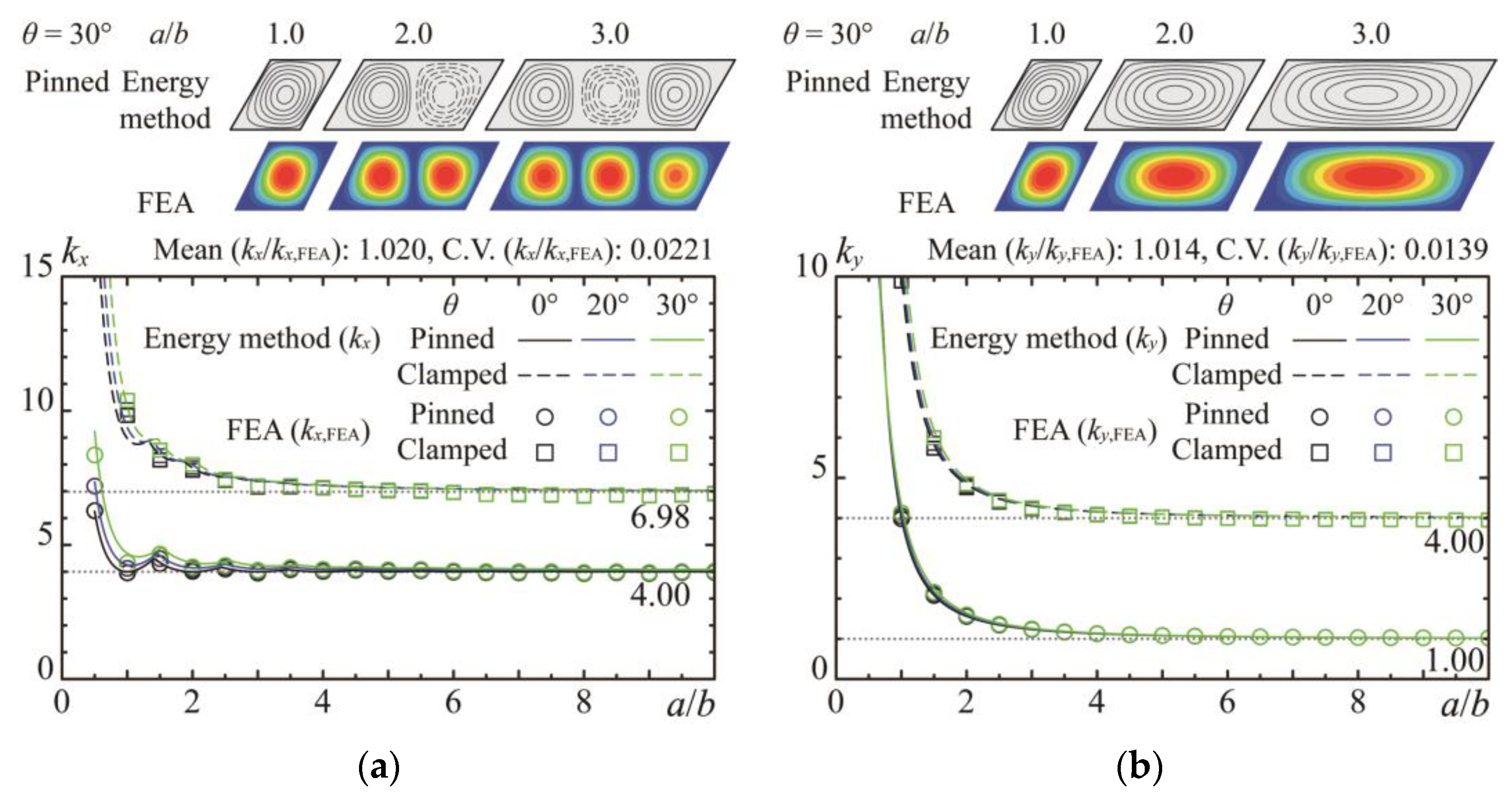
  • The critical buckling stress for skew plates under uniaxial stress was calculated through an energy method that employs the Cartesian coordinate system for displacement function derivation, contrasting with previous studies that used the coordinate system aligned with skew edges. The accuracy of the proposed method is corroborated using a comparison with buckling eigenvalue results from FEA, demonstrating superior precision over the prior literature.
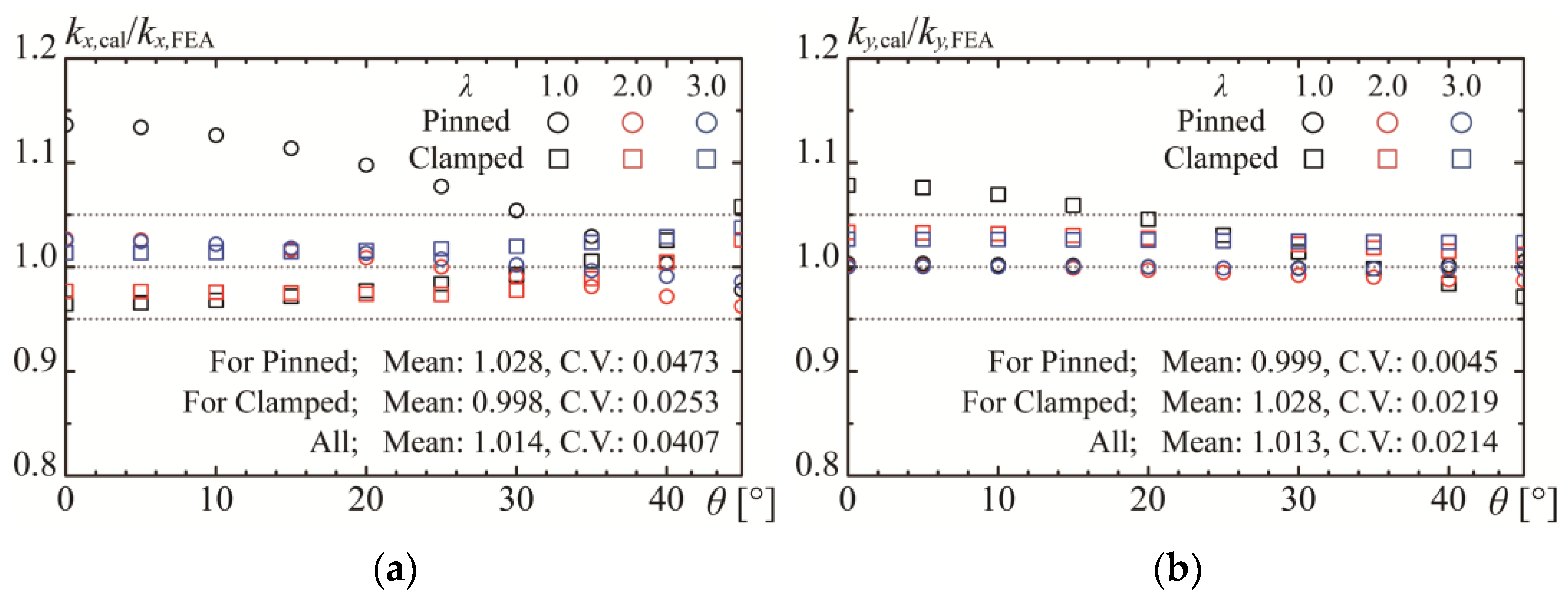
  • Design equations are derived to facilitate the simplification of buckling load calculations for stresses acting parallel or perpendicular to the longitudinal direction. The formulated design equations are applicable up to a skew angle of 45°, which is substantially within the practical range, as the actual panel angle in steel structural buildings is approximately 30°. Comparisons with FEA results validate the adequacy of these equations, enabling engineers to efficiently compute buckling loads for panel zones.
  • The impact of the skew angle on the buckling stress for skew plates under biaxial stress was determined to be insignificant. Based on this insight, the buckling stress correlation function for rectangular plates under biaxial stress, as proposed by Timoshenko, is applicable for estimating the buckling stress of skew plates.
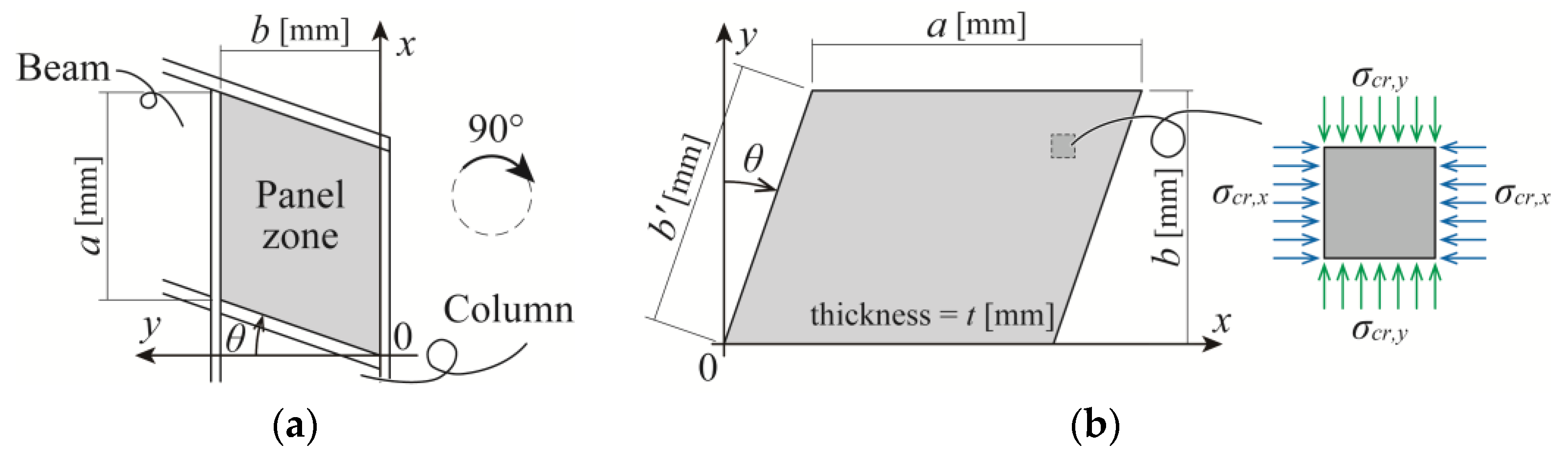
  • Panel zones in steel structures are subject to biaxial compressive stresses and experience a combination of stress states, including shear and bending. Leveraging the insights from this study in conjunction with analyses of additional stress states will contribute significantly to the effective and rational design of panel zones in the future.

Author Contributions

Conceptualization, K.M. and K.I.; methodology, K.M. and K.I.; software, K.M. and K.S.; validation, K.M.; formal analysis, K.M.; investigation, K.M.; resources, K.M. and K.S.; data curation, K.M. and K.S.; writing—original draft preparation, K.M.; writing—review and editing, K.M. and K.I.; visualization, K.M. and K.S.; supervision, K.M. and K.I.; project administration, K.M. and K.I.; funding acquisition, K.M. and K.I. All authors have read and agreed to the published version of the manuscript.

Funding

This study was funded by KAKENHI, grant number No. 20K14868, and KAKENHI, grant number No. 20H02294.

Data Availability Statement

The original contributions presented in the study are included in the article, further inquiries can be directed to the corresponding author.

Conflicts of Interest

The authors declare no conflicts of interest.

References

  1. Architectural Institute of Japan (AIJ). AIJ Recommendations for Design of Connections in Steel Structures; Architectural Institute of Japan: Tokyo, Japan, 2021; pp. 225–258. [Google Scholar]
  2. American Institute of Steel Construction (AISC). Seismic Provisions for Structural Steel Buildings; American Institute of Steel Construction: Chicago, IL, USA, 2016; pp. 9.1-103–9.1-105. [Google Scholar]
  3. Wittrick, W.H. Buckling of oblique plates with clamped edges under uniform shear. Aeronaut. Q. 1954, 5, 39–51. [Google Scholar] [CrossRef]
  4. Wittrick, W.H. On the buckling of oblique plates in shear: An examination of the critical shear stresses in 45-degree parallelogram plates. Aircr. Eng. Aerosp. Technol. 1956, 28, 25–27. [Google Scholar] [CrossRef]
  5. Iguchi, S. Eine Lösung für die Berechnung der biegsamen rechteckigen Platten. In Report Julius; Springer: Berlin, Germany, 1933. [Google Scholar] [CrossRef]
  6. Cook, I.T.; Rockey, K.C. Shear buckling of clamped and simply-supported infinitely long plates reinforced by transverse stiffeners. Aeronaut. Q. 1962, 13, 41–70. [Google Scholar] [CrossRef]
  7. Cook, I.T.; Rockey, K.C. Shear buckling of rectangular plates with mixed boundary conditions. Aeronaut. Q. 1962, 14, 349–356. [Google Scholar] [CrossRef]
  8. Ikarashi, K.; Utsuki, Y.; Mitsui, K. Elastic Shear buckling strength of L-shaped beam-to-column joint panels composed with I-shaped members. J. Struct. Constr. Eng. 2020, 85, 759–769. (in Japanese). [Google Scholar] [CrossRef]
  9. Ikarashi, K.; Utsuki, Y.; Mitsui, K.; Makino, Y.; Yamada, K. Evaluation Method of Ultimate Strength for L-shaped Beam-to-column Joint Panels Composed with I-shaped Members. J. Struct. Constr. Eng. 2020, 85, 1079–1089. (in Japanese). [Google Scholar] [CrossRef]
  10. Mitsui, K.; Ikarashi, K. Elastic shear buckling coefficients for oblique plates. Math. Probl. Eng. 2022, 2022, 9532380. [Google Scholar] [CrossRef]
  11. Timoshenko, S.P.; Gere, J.M. Theory of Elastic Stability, 2nd ed.; McGraw-Hill Book Co., Inc.: New York, NY, USA, 1959; pp. 319–439. [Google Scholar]
  12. Araghi, S.N.; Shanmugam, N.E. Strength of biaxially loaded orthotropic plates. Thin-Walled Struct. 2012, 53, 40–47. [Google Scholar] [CrossRef]
  13. Wang, X.; Wang, Y. Buckling analysis of thin rectangular plates under uniaxial or biaxial compressive point loads by the differential quadrature method. Int. J. Mech. Sci. 2015, 101, 38–48. [Google Scholar] [CrossRef]
  14. Wittrick, W.H. Buckling of oblique plates with clamped edges under uniform compression. Aeronaut. Q. 1953, 4, 151–163. [Google Scholar] [CrossRef]
  15. Durvasula, S. Buckling of Simply Supported Skew Plates. J. Eng. Mech. 1971, 97, 967–979. [Google Scholar] [CrossRef]
  16. Kennedy, J.B.; Prabhakara, M.K. Buckling of simply supported orthotropic skew plates. Aeronaut. Q. 1978, 29, 161–174. [Google Scholar] [CrossRef]
  17. Mizusawa, T.; Kajita, T.; Naruoka, M. Analysis of skew plate problems with various constraints. J. Sound Vib. 1980, 73, 575–584. [Google Scholar] [CrossRef]
  18. Mizusawa, T.; Leonard, J.W. Vibration and buckling of plates with mixed boundary conditions. Eng. Strct. 1990, 12, 285–290. [Google Scholar] [CrossRef]
  19. Yoshimura, Y.; Iwata, K. Buckling of simply supported oblique plates. J. Appl. Mech. 1963, 30, 363–366. [Google Scholar] [CrossRef]
  20. Ashton, J.E. Stability of clamped skew plates under combined loads. J. Appl. Mech. 1969, 36, 139–140. [Google Scholar] [CrossRef]
  21. Mishra, B.B.; Kumar, A.; Samui, P.; Roshni, T. Buckling of laminated composite skew plate using FEM and machine learning methods. Eng. Comput. 2021, 38, 501–528. [Google Scholar] [CrossRef]
  22. MSC Software: Marc 2022 Feature Pack 1, Volume A: Theory and User Information; MSC Software: Newport Beach, CA, USA, 2023.
  23. MSC Software: Marc 2022 Feature Pack 1, Volume B: Element Library; MSC Software: Newport Beach, CA, USA, 2023.
  24. Anderson, R.A. Charts giving Critical Compressive Stress of Continuous Flat Sheet Divided into Parallelogram-shaped Panels. In National Advisory Committee for Aeronautics (NACA); Langley Aeronautical Laboratory: Washington, DC, USA, 1951. [Google Scholar]
  25. Architectural Institute of Japan (AIJ). Recommendations for Stability Design of Steel Structures; Architectural Institute of Japan: Tokyo, Japan, 2018; pp. 180–228. [Google Scholar]
Figure 1. Stress state on panel zones varying with multiple loads.
Buildings 14 00901 g001
Figure 2. Skew plates under uniform biaxial normal stresses and its geometry: (a) Panel zone in moment frame; (b) Theoretical analysis model.
Buildings 14 00901 g002
Figure 3. Overview of FE model for skew plates under normal stress.
Buildings 14 00901 g003
Figure 4. Convergence study for mesh size.
Buildings 14 00901 g004
Figure 5. Graphical comparisons between present theoretical and FEA results and buckling modes under uniaxial compression where θ = 30°: (a) Under stress parallel to longitudinal direction; (b) Under stress perpendicular to longitudinal direction.
Buildings 14 00901 g005
Figure 6. Effect of geometries on the local buckling load: (a) Under stress parallel to longitudinal direction; (b) Under stress perpendicular to longitudinal direction.
Buildings 14 00901 g006
Figure 7. Effect of geometries on the local buckling modes with simply supported condition: (a) Under stress parallel to longitudinal direction; (b) Under stress perpendicular to longitudinal direction.
Buildings 14 00901 g007
Figure 8. Comparison between FEA results and calculations based on the proposed design equations: (a) Stress parallel to longitudinal direction; (b) Stress perpendicular to longitudinal direction.
Buildings 14 00901 g008
Figure 9. Correlation curve of buckling coefficient for simply supported condition: (a) a/b = 1.0; (b) a/b = 3.0; (c) a/b = 5.0.
Buildings 14 00901 g009
Figure 10. Correlation curve of buckling coefficient for clamped-supported condition: (a) a/b = 1.0; (b) a/b = 3.0; (c) a/b = 5.0.
Buildings 14 00901 g010
Table 1. Comparisons with buckling coefficients where θ = 30°.
Stress
Directions
Boundary Conditions Aspect Ratio a/b
0.51.01.52.03.0
σcr,xPinnedPresent study8.824.644.914.384.27
FEA8.354.334.664.184.05
Durvasula [15]7.804.814.784.52
Kennedy [16]7.204.154.193.90
Anderson [24]9.606.626.265.21
ClampedPresent study29.2210.458.858.097.42
FEA25.9510.398.537.997.21
Wittrick [14]10.23
σcr,yPinnedPresent study16.824.362.281.661.27
FEA16.874.132.161.591.24
Durvasula [15]13.804.001.981.51
Kennedy [16]12.533.071.761.40
ClampedPresent study38.2811.416.194.964.33
FEA35.1110.846.004.854.25
Disclaimer/Publisher’s Note: The statements, opinions and data contained in all publications are solely those of the individual author(s) and contributor(s) and not of MDPI and/or the editor(s). MDPI and/or the editor(s) disclaim responsibility for any injury to people or property resulting from any ideas, methods, instructions or products referred to in the content.

