1. Introduction
Current security challenges require rethinking of the need for structural protection against explosive events. On the one hand, major bomb attacks, such as those in Oslo (2011) or in Brussels (2016), highlight the vulnerability of public spaces. On the other hand, accidental explosions, such as in the ports of Tianjin (2015) and Beirut (2020), lead to discussions about the necessary security in exposed areas. The protection of critical facilities has become even more prominent due to the ongoing war in Ukraine since the beginning of 2022.
Conventional windows made with frames of flexible materials, such as un-plasticized polyvinyl chloride (uPVC) or wood, are known to be particularly vulnerable to blast loads. If a glazing unit breaks, glass fragments are propelled by the blast wave at high velocity into the interior and exterior of the building. Annealed glass, commonly used in conventional windows, can shatter into sharp shards, which poses a high risk of cut injuries for personnel [
1]. Additionally, the blast may also tear off the window frame from its anchorage. Such heavy fragments can cause blunt trauma if they collide with individuals [
2,
3].
This article focuses on retrofitting existing windows. The aim is to minimize the risk of injury in the event of an explosion while preserving the existing building structure. Using retrofitted protective measures represents a compromise. On the one hand, retrofitting can be performed relatively uncomplicated and quickly compared to replacing existing windows with blast-resistant security windows. A sustainable solution may be possible as the existing windows will be preserved. On the other hand, retrofitted windows do not currently offer the same level of protection as blast-resistant security windows. Moreover, retrofit measures are typically tested on a stand-alone basis, rather than on an entire window system with the complex interaction of its components. This encourages further research into retrofit measures and testing them in realistic situations on full-scale window systems. Examples of the most common retrofit measures are anti-shatter films and catcher systems.
1.1. Anti-Shatter Films (ASF)
In engineering practice, so-called anti-shatter films (ASFs) are often used to reduce risks during explosive events associated with shattered glass panes [
4]. Similar to laminated safety glass, glass fragments adhere to the ASF after the glass pane breaks, reducing the risk of cut injuries. The thin transparent polymer films can be installed directly onto an existing glazing unit. The required thickness of ASFs depends on the desired level of protection and the dimensions of the glazing unit. Typical thicknesses range from approximately 0.1 mm to 0.5 mm [
5,
6]. Further information on the characteristics of ASFs for blast protection can be found in [
7,
8]. It should be noted that the durability of ASFs has not yet been conclusively assessed [
9]. Often a warranty of about 10 years is given.
In Europe, ASF certification testing typically follows the EN 13541:2012 [
10] test method. The respective shock-tube test is performed on an ASF-retrofitted glazing unit with well-defined dimensions in a controlled setting. Tested ASF-retrofitted glazing units currently achieve the resistance class ER1 according to EN 13541:2012, which corresponds to a blast load with a reflected peak overpressure
of 50 kPa and a reflected maximum impulse
of 370 kPa∙ms.
It is important to stress that the described certification tests of EN 13541:2012 solely determine the blast-resistance of glazing units, without considering the overall performance of the entire window system. For example, the test method specifies that the glazing unit is clamped in a rigid steel frame. Conventional window frames are somehow rather flexible, and it is often not possible to clamp the glazing in the glazing rebate. In the experimental study presented throughout this article, we will focus on the blast-resistance of full-scale window systems that are equipped with ASF-retrofitted glazing units. The presented approach corresponds more closely with practical applications [
11], since it considers the entire window assembly rather than just the glazing unit itself.
1.2. Catcher Systems
Catcher systems are used if parts of the window need to be stopped from being propelled into the protected area. Commonly applied are catcher-cable systems, catcher-bar-systems, or blast curtains:
Catcher-cable systems (CCS) are installed together with ASF-retrofitted glazing units. Larger fragments can be caught by several cables placed in the interior of the room at close proximity to the window.
Catcher-bar systems are installed together with ASF-retrofitted glazing units and consist of several steel bars placed at close proximity to the window at the inside of the room. The protective principle is similar to that of a catcher-cable system; however, the bars are stiff obstacles, while the cables show a more flexible response.
Blast curtains are typically made from heavy-duty fabrics and are placed in front of windows at the inside of the room. Fragments are caught by the fine mesh of the curtain. Note that daylight and comfort in the building may be affected as the curtains must be kept always closed.
1.3. Objective and State of the Art
The primary objective of this study is to evaluate the effectiveness of catcher-cable systems (CCSs). Experimental and numerical studies in this particular application field are relatively sparse, especially including full-scale window systems.
One of the few studies on CCSs for retrofitting full-scale window systems was presented by Dogruel and Field [
12]. In this study, free-field blast tests were performed on historic wood-framed windows. The windows were subjected to blast loads that are slightly less intense than those required for ER1-certification (27.5 kPa reflected overpressure and 193 kPa∙ms reflected maximum impulse). Laminated glass was used to replace the conventional glass panes of the historical windows. Note that replacing the glazing of existing windows can be relatively costly compared to retrofitting the window with anti-shatter films. In the study, a CCS is installed to stop window fragments from being propelled into the protected area. It consists of 2.6 mm diameter steel wire ropes included in so-called blast-blinds. Hiding the protection in the blinds can be an architecturally appealing solution.
In summary, the tests of Dogruel and Field [
12] achieved GSA Condition 3b [
13], which is associated with high protection and a low hazard level [
11]. The experimental study concluded that for large-paned windows at least two cables are required to effectively prevent glass fragments from being propelled into the protected area.
The efficiency of a CCS is generally driven by the performance of the cables, the cable anchorage, and the response of the impacting fragments [
14]. A rather simplified approach would be to design catcher-cables and cable anchorage directly on the distributed blast loads. In fact, the tensile forces in the cables are a result of the impact of the window fragments and are characterized by the impact velocity and the mass of the fragments. Depending on the shape of the window fragments, the CCS may be subjected to local punctual loads or extended areal loads. Moreover, the flexibility of the cables influences the reaction forces.
Even though the failure-mechanism of catcher-cables essentially corresponds to the cable tensile forces, measurements during experiments with entire retrofitted windows are rather rare. Remennikov and Brodie [
15] have published an experimental study on cable forces and how their flexibility affects the response of a CCS. In this study, the catcher-cables were subjected to local impacts, which may represent a single impacting frame fragment. In this case a 600 kg hammer was utilized to be dropped with velocities of 1.1 m/s to 1.29 m/s onto the center span of the steel cables. The following can be concluded from the study [
15]:
By using energy-absorbing plates for anchoring the cables, the tensile forces can be reduced by approximately one-third compared to rigid anchorage.
Since greater cable deflections can be achieved, the energy-absorbing anchorage resulted in an increase in the deceleration duration of the impacting hammer compared to the rigid anchorage.
Conversely, the extended deceleration time results in lower forces on the fragments. This concept shall prevent fragments from being “cut” during the impact.
Similar measures for controlling energy dissipation at the cable anchorage are well known for cable-net façades, e.g., in [
16,
17] and curtain walls, e.g., in [
18]. Specific viscoelastic and frictional devices can be applied to control the tensile forces at the connection between glass and cables, as well as at the anchorage of the cables. A numerical approach to study the cable forces in a CCS was presented by Lan and Crawford [
19]. However, the response of the CCS was evaluated solely for the impact of an ASF-retrofitted glass pane, without considering possible fragments of window frames.
This article presents new experimental research on the effectiveness of catcher-cable systems (CCSs) in combination of anti-shatter films (ASFs) to retrofit windows. The blast tests are performed using entire window systems, i.e., conventional single-casement windows with insulating glass units (double-paned) and window frames made of un-plasticized polyvinyl chloride (uPVC). In addition to these retrofit measures (CCS and ASF), the influence of the steel profiles installed in the window frames on the response of the windows is examined. Note that based on the available literature, it can be concluded that such conventional single casement windows have generally not been tested against blast loads yet. Therefore, the study also includes a discussion on the failure mechanism of such windows.
In the blast tests, the windows are subjected to blast loads that meet the requirements for ER1-certification according to EN 13541:2012 with a reflected peak overpressure of 66.7 kPa and a reflected maximum impulse of 417.6 kPa∙ms. The CCS is exposed to window fragments with a realistic mass, stiffness, and velocity in the event of a window failure because the blast tests are performed on entire window systems. Various measurement methods were used to capture the velocity of the window fragments, the dynamic cable forces, and the hazard. The captured data provide valuable information for the design and implementation of catcher-cable systems for existing buildings, which can improve the occupant safety in the event of an explosion.
2. Test Setup
The blast tests are carried out in the gas-driven shock-tube Blast−STAR (Blast Security Test and Research Facility) located at the Fraunhofer Ernst Mach Institute (EMI). The basic layout of the shock-tube facility can be found in Millon and Haberacker [
20].
2.1. Overview
Table 1 summarizes the 10 configurations examined in the shock-tube tests. All test specimens are conventional single-casement windows with insulating glass units (double-paned) and window frames made of un-plasticized polyvinyl chloride (uPVC). Various retrofit-configurations, including anti-shatter films (ASFs) and catcher-cable systems (CCSs), are applied to the conventional windows. In addition, the influence of steel profiles installed in the window frames is examined.
The test program is structured as follows.
The first test U1 is carried out with a specimen referred to as “basic unprotected”. The tested conventional window has no blast protective measures and serves as a benchmark for all other tests.
Subsequently, the effectiveness of an ASF applied to the glazing of such a basic unprotected window is evaluated in tests ASF01 to ASF03. In practice, window frames are often fitted with steel profiles to meet the increased structural requirements. For this reason, the specimen in test ASF03 is additionally equipped with steel profiles to determine the contribution of the increased frame stiffness to the overall blast resistance of the window.
Finally, six shock-tube tests (CC01 to CC06) are performed on specimens equipped with CCSs and ASFs. The test series examines two different stiffnesses of the CCS (soft and hard) to determine their effect on protection. In addition, the window frames in tests CC03 and CC04 have steel profiles installed, while the rest of the tests are conducted without steel profiles.
The below sections detail the respective configurations and the retrofit measures.
2.2. Basic Unprotected Configuration of the Tested Windows
In test U1 (
Table 1), a basic unprotected configuration is tested.
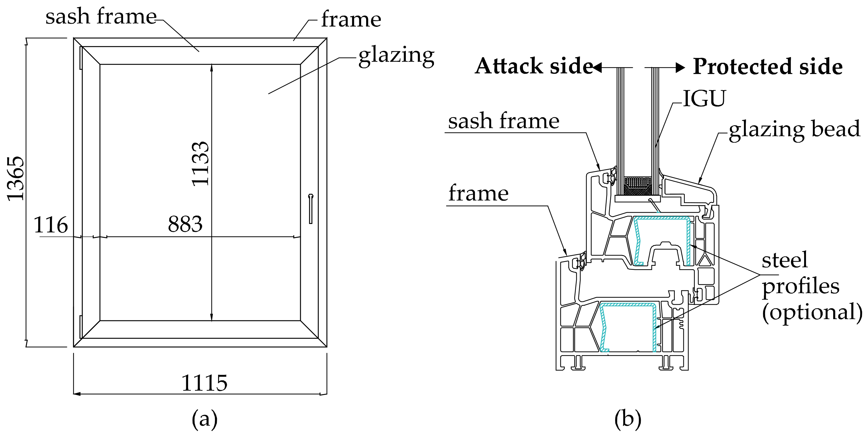
Figure 1 shows technical details on the components of the window. The conventional window consists of three main parts: the frame, the sash frame, and the insulating glazing unit (IGU).
The IGU consists of an outer 4 mm-thick float glass pane, a 16 mm-wide inter-pane cavity filled with an argon gas mixture, and an inner 4 mm-thick float glass pane. The dimensions of the IGU are 883 mm in width and 1133 mm in height (
Figure 1a), which is consistent with the glazing dimensions of 900 mm × 1100 mm, as outlined in the EN 13541:2012 test method [
10]. Therefore, the test results of these full-scale studies can be compared to the results of the ASF certification tests on single glazing units. But remarkable discrepancies at the glazing support conditions are valued in this test series.
Figure 1b shows a cross section of the window. The frames consist of multiple thin-walled hollow chambers that improve thermal efficiency. Optional in the test series are steel profiles that are fitted into the hollow chambers of the window frames during production. These steel profiles are typically used in uPVC-window frames to add strength and stability to the window system. However, they usually end several centimeters from the corner joints of the frames, thus adding no additional strength to the frame corners. The unprotected window in test U1 was designed without steel profiles, representing a window configuration with low frame strength.
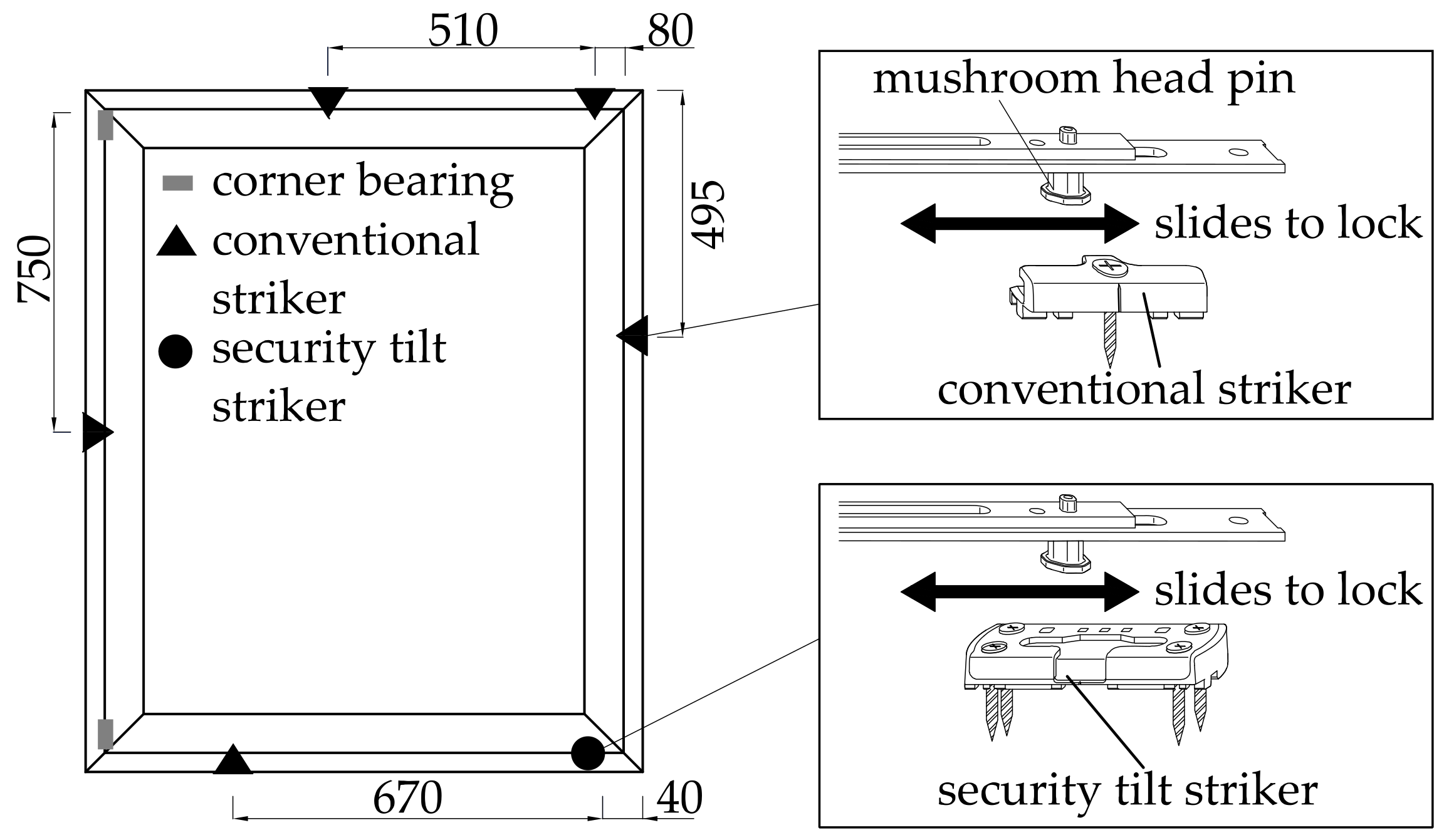
Fitting systems are required to open and lock sashes of casement windows. With the window locked, the fittings provide the mechanical load-bearing connection between the sash (the moveable part of the window) and the frame (the stationary part of the window). The tested windows are equipped with a conventional fitting system, which provides low resistance against burglary (resistance class RC1 N according to EN 1627:2021 [
21]). Here, five conventional strikers, one security tilt striker, and two corner bearings are installed. The arrangement is illustrated in
Figure 2. The counterpart of the strikers are mushroom head pins that can slide into the recesses of the strikers.
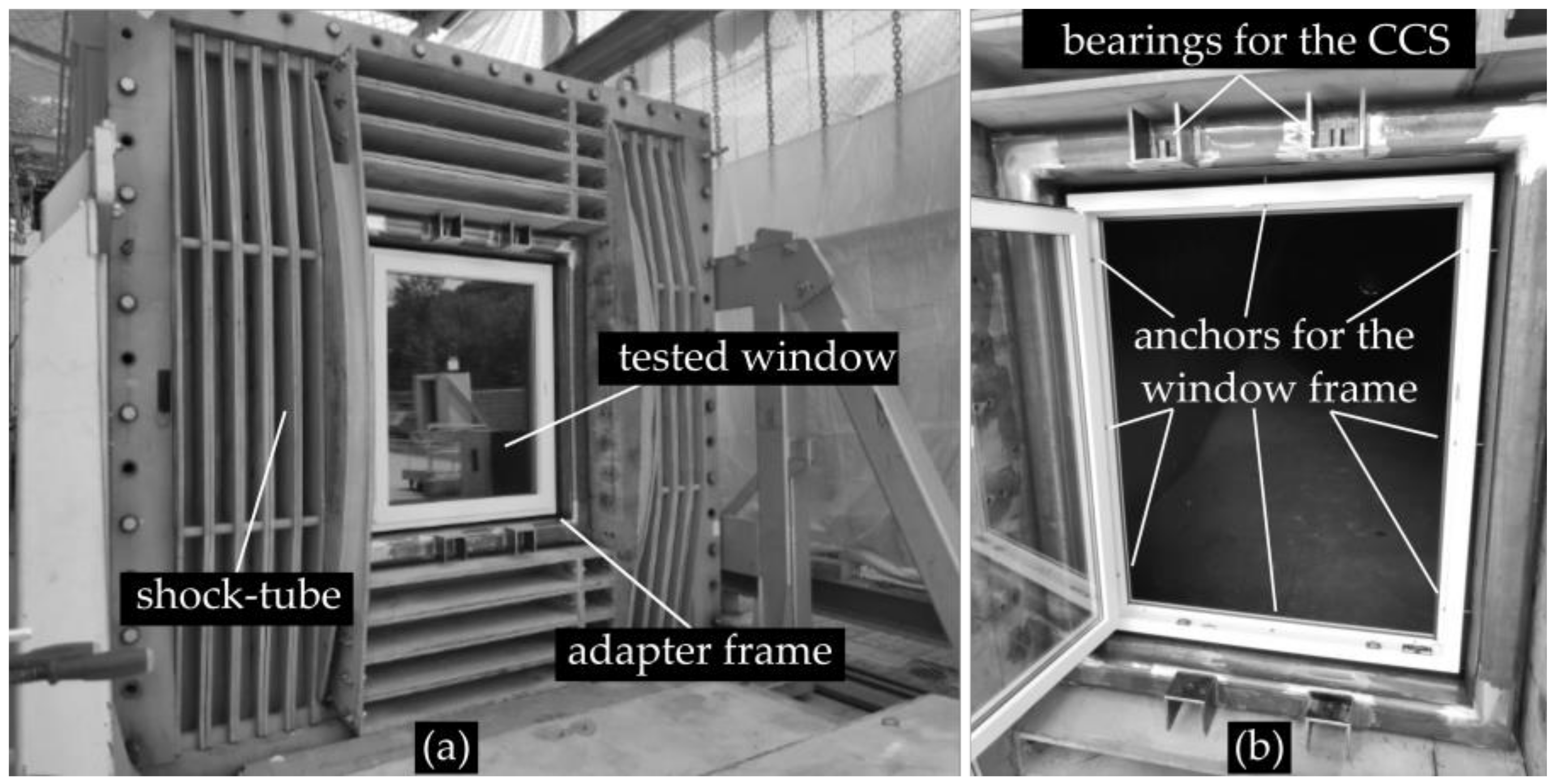
Figure 3 shows the window installed in the shock-tube. It is fixed with 8 anchor pins to a steel adapter frame that was firmly bolted to the mounting frame of the shock-tube (
Figure 3a). The adapter frame also provides the bearings for the catcher-cable system (
Figure 3b), which will be discussed in
Section 2.3.
All window configurations explained in the following are retrofitted upgrades of the basic unprotected configuration U1.
2.3. Tested ASF-Retrofitted Configuration
Three tests are performed with ASF-retrofitted configurations without a catcher-cable system (ASF01, ASF02, and ASF03,
Table 1). The applied anti-shatter films (ASFs) were selected because they are a certified product in accordance with the EN 13541:2012 test method. They have the following characteristics:
The three conducted tests, ASF01, ASF02, and ASF03 (
Table 1), also examine variations in the frame’s stiffness. Tests ASF01 and ASF02 are carried out without steel profiles strengthening the frame (
Figure 1b). Test ASF03 is performed using such steel profiles.
2.4. Tested ASF-Retrofitted Configuration with Catcher-Cable System
Six tests, designated as CC01 through CC06 (
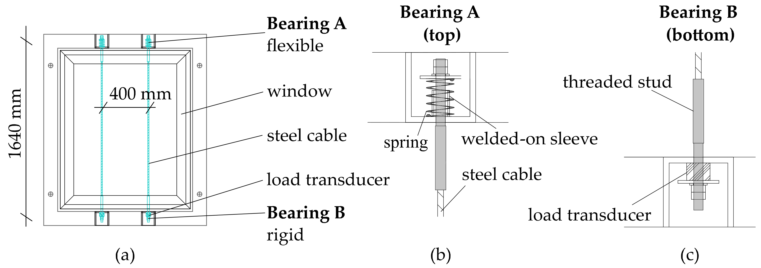
Table 1), are performed using a combination of an ASF-retrofitted glazing unit and a catcher-cable system. The catcher-cable system (CCS) comprises two stainless steel (type 1.4401) wire ropes. These are positioned 155 mm from the window frame on the protected side. The spacing between the two steel cables is 400 mm. The cable length between each bearing is 1640 mm. The bearings are located at the top and bottom of the adapter frame (
Figure 3). In practical applications, the cables would be anchored in the floor and ceiling of the room. Alternatively, horizontal anchorage to adjacent structural components is also possible.
Figure 4 illustrates details of the CCS. At bearing A, located at the top, the steel cables are flexibly anchored by elastic compression springs (spring-supported). If tensile forces are applied to the cables, the springs are compressed. Lateral deflections of the springs are avoided by using welded-on sleeves. At bearing B, located at the bottom, the steel cables are rigidly anchored to the adapter frame (
Figure 4). Here, the tensile forces are measured using cylindrical load transducers.
The test series examines two different stiffnesses of the CCS. System properties are summarized in
Table 2. The “soft” configuration comprises an 8 mm-thick steel cable and an elastic compression spring with a stiffness of 71 N/mm. The “hard” system is composed of a 10 mm-thick steel cable and an elastic compression spring with a stiffness of 186 N/mm. The static ultimate tensile strength of the soft system is 21.84 kN, while that of the hard system is 32.19 kN. Both systems can achieve a maximum spring deflection of about 15 mm in compression.
The window frames in the tests CC03 and CC04 have steel profiles installed (
Table 1). In the remaining six tests, the window frames are assembled without steel profiles.
2.5. Instrumentation and Documentation
The tests use several methods of documentation, which are described below.
2.5.1. Blast Load and Pressure Measurements
The blast loads are measured by two pressure gauges (D1 and D2) installed next to the tested windows. The gauges used are model 8510C-15, manufactured by Endevco (Irvine, CA, USA). They can accurately measure peak overpressures of up to 103.42 kPa (15 Psi), with a maximum possible error of 0.5% in the measured values [
23]. All measured peak overpressures are below this given limit (
Table 3).
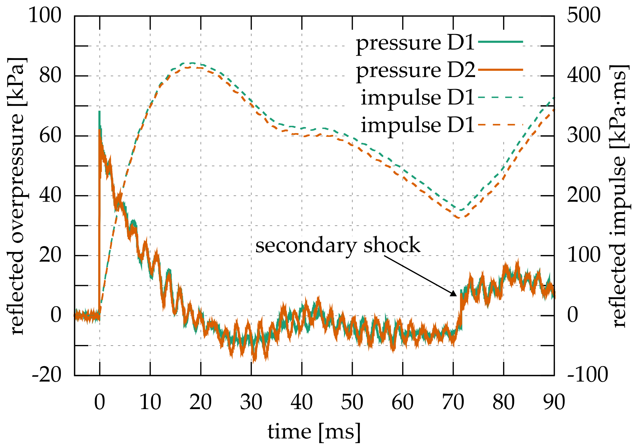
Figure 5 depicts the measured reflected overpressure–time histories from test ASF01 and the respective reflected impulse–time histories. The overpressure–time histories at the two pressure gauges D1 and D2 are almost identical. Slight deviation in the blast loads can be observed after reaching the maximum reflected impulse at around 22 ms. The deviations are likely due to the asymmetric displacement of the torn-off window parts.
The initial settings of the shock-tube were established to meet the blast intensity for ER1-certification according to EN 13541:2012.
Table 3 summarizes the average measured reflected blast loads at the two pressure gauges. The actual blast loads deviate slightly from the ER1 target values. The mean value of the reflected peak overpressures from all 10 tests is 66.7 kPa (
Table 3), which is approximately 1/3 higher than the target value of 50 kPa. The mean value of the reflected impulses is 417.7 kPa∙ms, which is also slightly higher than the target value of 400 kPa∙ms. Nevertheless, these two blast characteristics correspond well to the load required for ER1-certification. The measured average duration of the positive pressure phase is 1.7 ms shorter than the target value of 20 ms. This minor discrepancy is accepted.
By evaluating the statistical data, a maximum coefficient of variation of 4.6% at the maximum impulse can be found (
Table 3). This indicates a relatively low statistical scatter compared to a free-field blast [
24]. Consequently, during the test series, the 10 windows were consistently exposed to similar blast loads.
Typical for shock-tube tests is the multiple exposures of the test specimen to blast loads. This rather undesirable effect occurs because the blast wave is re-reflected in the partially confined shock-tube [
25]. In the presented test series, the arrival of the secondary shock is observed with the secondary increase in overpressure starting at about 70 ms (
Figure 5). At this instant, all tested windows were already shattered. Thus, it can be concluded that the secondary shock does not have influence on the structural behavior.
2.5.2. Displacement and Velocity
The displacement of the tested windows are determined by digital image correlation (DIC) following the method described by Schneider et al. [
26]. Each test is recorded at a frame rate of 4000 frames per second, with an image resolution of 1024 × 1024 pixels. The velocity is computed based on numerical differentiation of the displacement-time histories.
Alternatively, in test U1 (unprotected window), the displacement of the window is measured using laser rangefinders. The laser rangefinders are attached to a wooden support beam, which is arranged at the protected side of the window. This method has the disadvantage of partially obstructing the flight trajectory of the window fragments. Therefore, the DIC method proved to be more suitable for this test series.
2.5.3. Cable Tension
The dynamic cable tensile forces in the CCS are measured using cylindrical force transducers located at the bearings B (bottom,
Figure 4a) of the steel cables. From the measured strain in the cylinders, the force–time histories in the cables are computed.
2.5.4. Hazard Capture
The method described in ISO 16934:2007 [
27] is used to evaluate the hazard from fragments propelled into the protected area. The protected area (
Figure 6) is subdivided into 6 hazard zones, A to F, respectively. More details on the procedure can be found in [
11].
To assess the hazard posed to individuals, a witness wall is placed at a distance of 3.0 m to the specimen (
Figure 6a). The witness wall consists of 15 individual witness panels made of extruded polystyrene foam (XPS). The material of the panels has an elastic modulus of 3.0 MPa and a mass density of 33.0 kg/m
3. These properties comply with the recommendations of ISO 16934:2007 [
27]. The total dimensions of the wall are 3.75 m × 3.0 m (width × height).
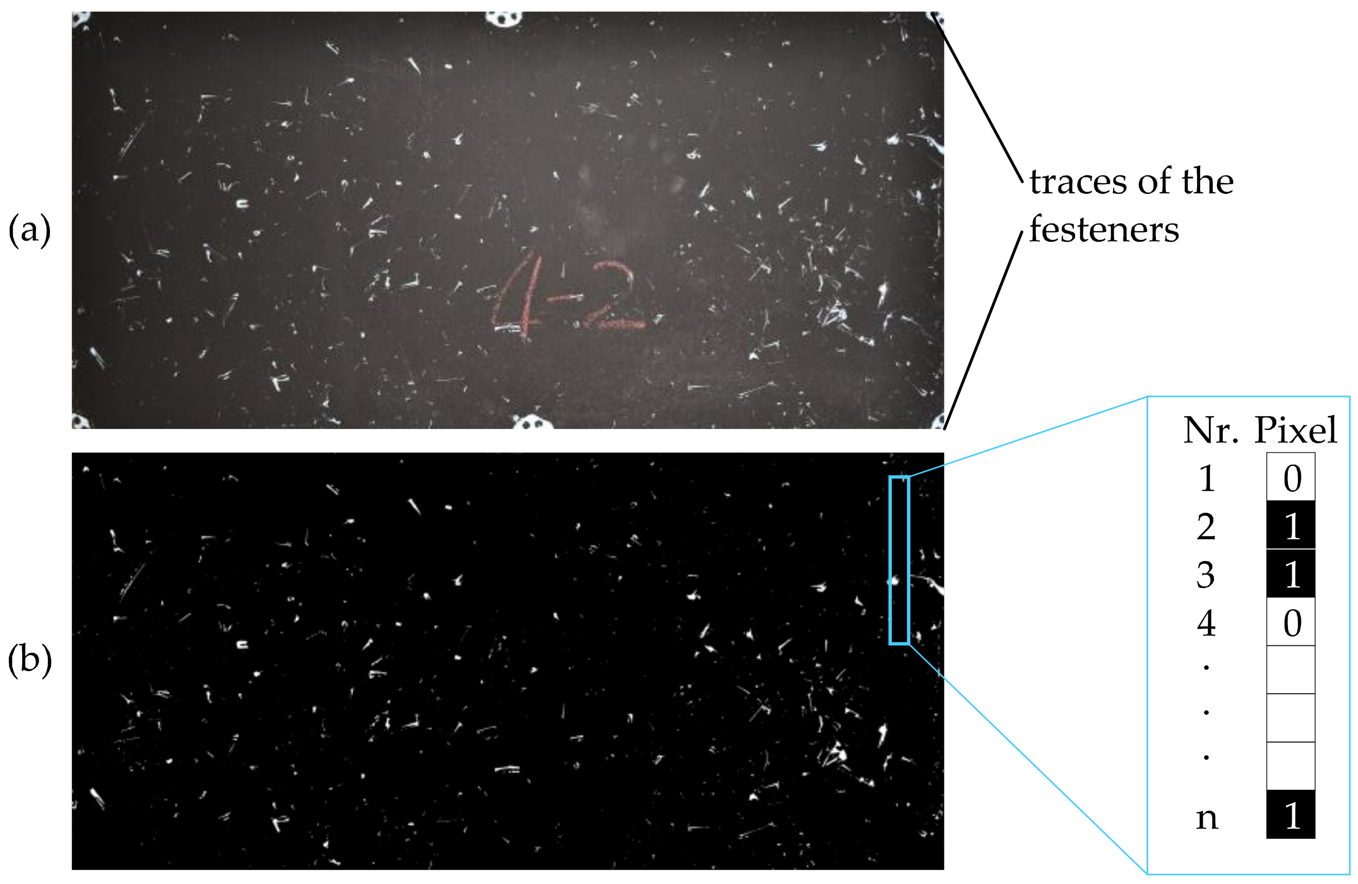
2.5.5. Optical Analysis for Hazard Assessment
A novel approach was used to assess the impact of the window fragments on the witness wall. This includes taking high-resolution digital photographs (5570 × 3710 pixels) of the damaged panels after the tests (
Figure 7a). The photographs are later digitally aligned and cropped to precisely correspond with the outer boundaries of the designated witness panels. The marks left by the fragments are clearly visible on the panel’s surface, since the initially white witness panels were painted black prior to the test.
A method proposed by Dorafshan et al. [
28] is implemented to determine the damage on the panels by analyzing the high-resolution photographs. This method is widely accepted for detecting defects on surfaces with a monochrome texture, such as cracks in concrete structures. It incorporates subroutines, such as filtering, thresholding, and morphological operations. The following procedure is employed during the analysis:
To ensure an accurate analysis, all traces of fasteners and labels on the panels (as seen in
Figure 7a) were manually removed from the images. In addition, the captured damage is carefully compared visually with each photo of the witness panel.
Figure 7b shows the result of the analysis.
By employing the image-analysis method, a binary representation of the panel is produced (
Figure 7b). Black pixels represent undamaged regions, while white pixels indicate damaged regions. T proposed method not only locates damaged areas, but also helps quantify the hazard. This is performed by analyzing each row and column of pixels in the image and calculating the percentage of the damaged area.
3. Test Results
3.1. Basic Unprotected Configuration
In test U1, the basic unprotected window was tested.
Figure 8 shows the global failure mode of the window taken from the high-speed video recordings. The window sash was torn off from the frame by the blast load and propelled into the protected area. After about 39 ms, the torn-off window sash collided with the wooden support beam that was used to attach the laser rangefinders. While the sash frame was stopped by the wooden support beam, the glass fragments proceed unhindered into the protected area.
3.1.1. Failure Mechanisms of the Window
The high-speed video recordings in
Figure 8 suggest a combined failure of the frame corners and the fitting system of the window, which caused the window sash to be torn off. To detail the failure at the frame corners,
Figure 9a depicts the lower right corner at 15 ms, during the overpressure phase of the blast. Along the connecting surfaces of the uPVC frames, significant separation cracks appeared almost simultaneously within a period of 6.0 ms to 6.7 ms. In comparison, as can be seen in
Figure 8, the failure of the glazing occurs much later at approximately 20 ms. In conclusion, the frame corners can be identified as one of the vulnerable parts of the window that are currently not strengthened.
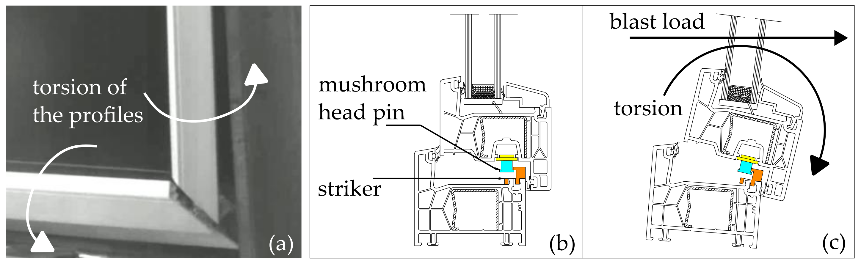
To elaborate on the observed failure mode at the corners of the frame,
Figure 9b,c shows cross-sections of the window, (b) in the original unloaded condition, and (c) deformed under the blast load. The deformation of the sash and frame profiles was primarily due to torsion caused by an eccentric load transmitted by the glazing unit. After exceeding the strength of the uPVC at the frame corners, smooth separation cracks appeared along the joint surfaces.
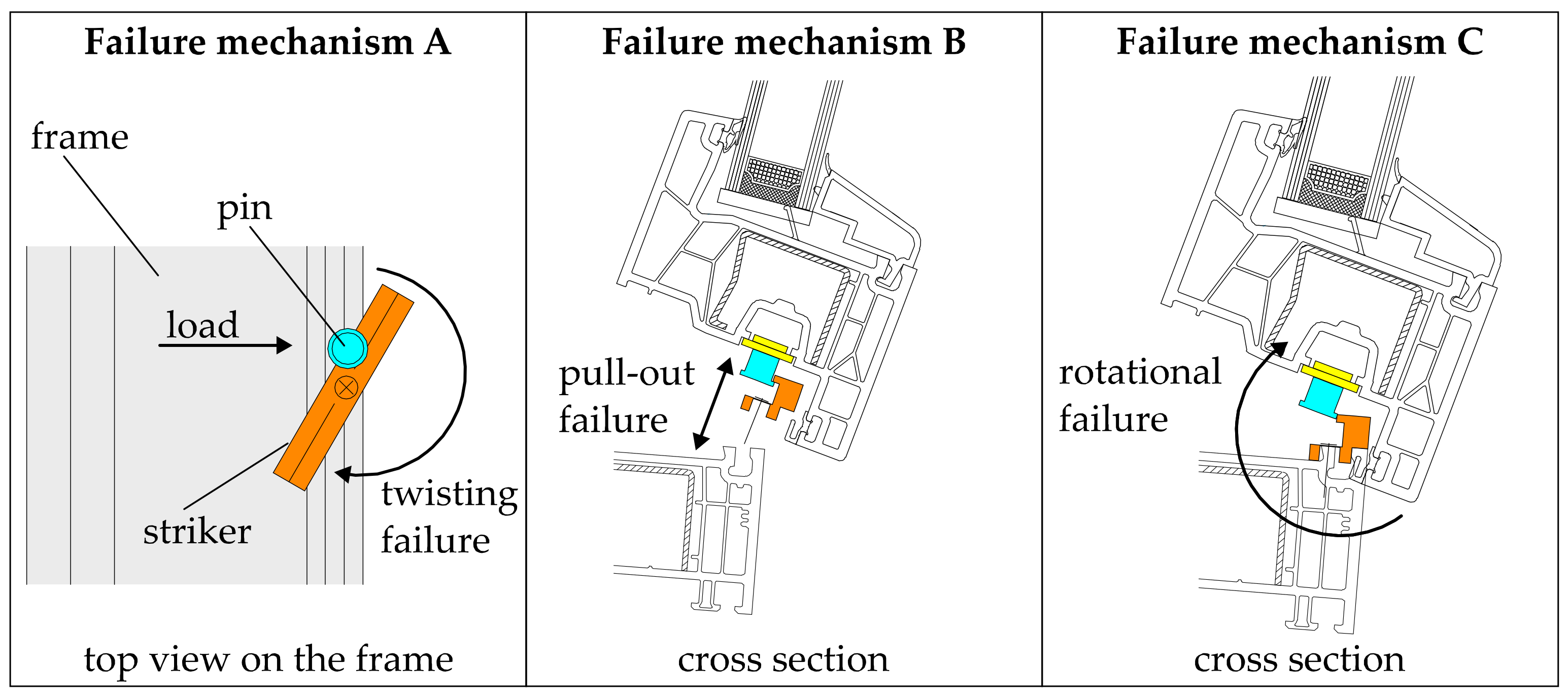
The following failure mechanisms of the fitting system, or a combination of them, are possible. Schematic representations are given in
Figure 10.
Failure mechanism A: The centrally arranged screw and the interlocking connection to the frame cannot sufficiently prevent the striker from twisting.
Failure mechanism B: The pull-out resistance of the screw is exceeded, resulting in the striker to be torn-off from the frame.
Failure mechanism C: The mechanism unlocked due to the large rotational movement of the sash frame. In this case, the mushroom head pin disengages from its anchorage within the striker.
In all failure mechanisms of the fitting system described above, forces between the frame and the sash can no longer be transferred. The window sash tears off from the frame. In the test series conducted, it was observed that almost all conventional strike plates were torn from the frame, i.e., failure mechanisms A and B did most likely occur.
3.1.2. Displacements and Velocities of the Fragments
In the test U1 with an unprotected window, the displacements of the window were measured using two laser rangefinders, targeting the sash frame and the center of the glazing.
Figure 11 shows the obtained displacement– and velocity–time histories at those two locations.
Since the glazing and the sash frame were torn off simultaneously from the window frame (
Figure 8), the measured displacements and velocities increase equally, as expected. The maximum velocity reached is about 15 m/s. The measurements stop abruptly due to the impact of the fragments on the laser rangefinders mounted on the wooden beam.
3.1.3. Hazard Level
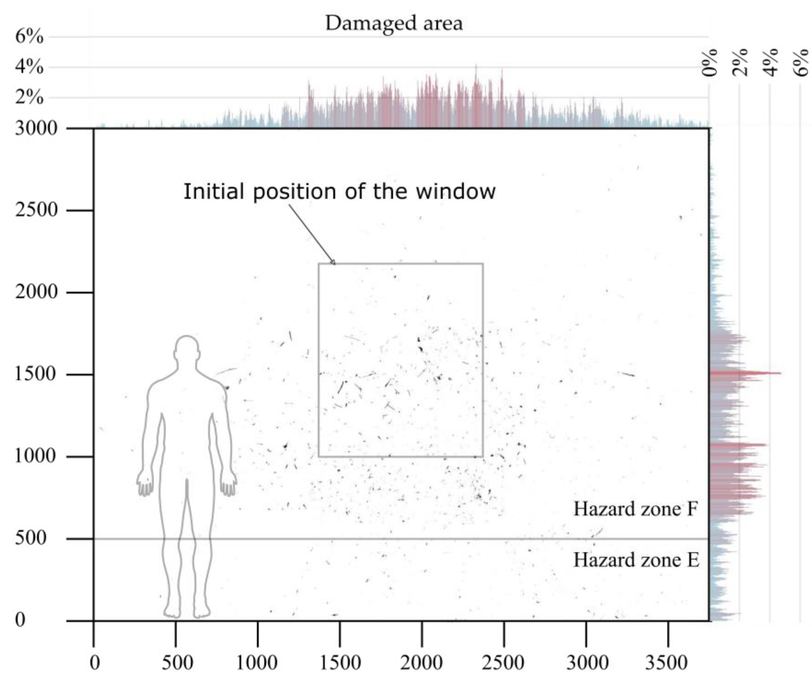
Figure 12 shows the witness wall, which was analyzed using the optical method described in
Section 2.5.4. For orientation, the original position of the unprotected window and a person with a height of 175 cm are indicated. A very large number of glass fragments impacted the witness wall. Some of the glass fragments bounced off the panel-surface and left cut marks, and others penetrated directly into the witness panel. The penetrated glass fragments had a maximum length of up to 16.5 cm and a maximum mass of about 100 g.
About 0.99% of the total area of the witness wall was damaged in the test U1, which corresponds to a total area of about 1114 cm2. The most severe damage can be seen in the center of the witness wall at a height of about 1.5 m above the ground.
In summary, the evaluation of the witness panel concludes hazard level F according to ISO 16934:2007 [
27]. It must be noted that the impact of the sash frame on the witness wall was prevented in this test by the wooden support beam for the laser rangefinders (see
Figure 8). However, from the initial velocity of the sash frame of about 15 m/s (see
Figure 11), it can be concluded that the sash frame would also hit the witness wall in hazard zone F.
3.2. Windows Retrofitted with ASFs
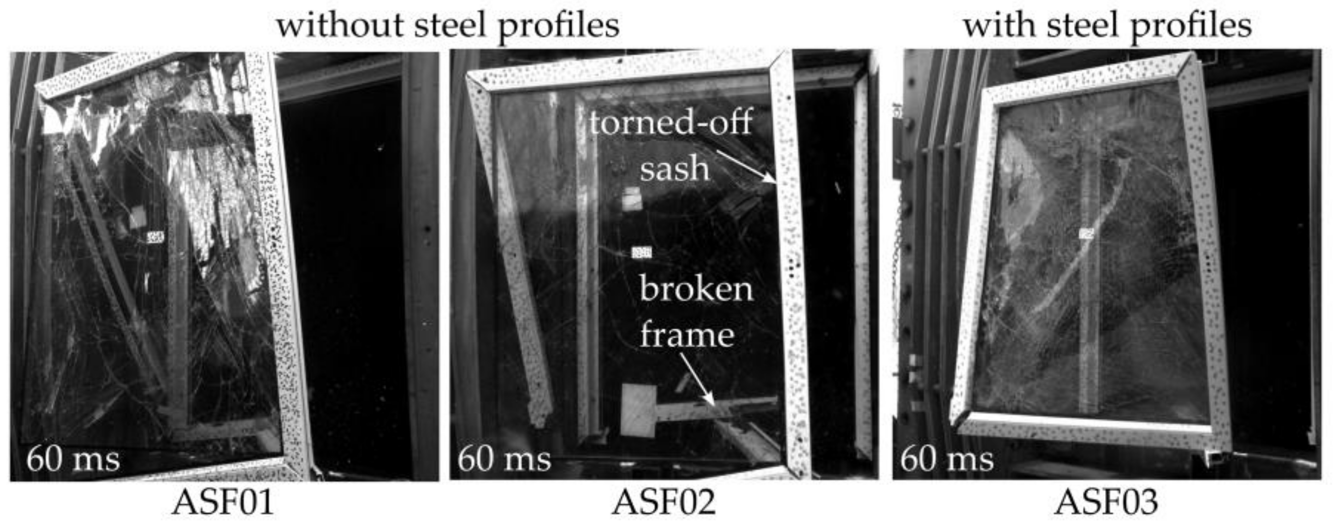
Three tests were performed on windows with ASF-retrofitted glazing units (ASF01, ASF02, and ASF03).
Figure 13 shows the corresponding high-speed video recordings at 60 ms. In each test, the sash was torn off from the window frame. Again, the loss of structural integrity is attributed to separation cracks at the frame corners, as well as the failure of the fitting system.
Variation in the strength of the window frames was studied by using steel profiles. In the tests ASF01 and ASF02, the window frames were fabricated without steel profiles fitted into the window frames (
Table 1). In test ASF03, the window frames were reinforced by additional steel profiles. When analyzing the high-speed video footage in
Figure 13, it appears that the sash with steel profiles (tests ASF03) was propelled more compactly into the protected area than the sash without steel profiles (tests ASF01 and ASF02). In addition, the lower window frames without steel profiles were broken in the middle.
In summary, using ASFs as retrofit measures had no influence on the failure mechanism of the window. Moreover, steel profiles in frames do not prevent the sash from being torn off. Regardless, the sash equipped with steel profiles appeared to fly more compactly into the protected area.
3.2.1. Displacements and Velocities of the Fragments
The displacements and velocities of the fragments were captured using the DIC method. The tracking was performed at several marker points located at the center of the glazing and at the sash frame.
Figure 14 shows the measured displacement–time histories of test ASF01 and the corresponding velocity–time histories.
As expected, almost similar displacements and velocities are obtained at the sash frame and at the center of the glazing. The sash was accelerated up to a velocity of about 6 m/s to 8 m/s during the first 10 ms. Subsequently, the velocity–time history appears to reach a kind of plateau. With the onset of the negative-pressure phase starting at about 20 ms (
Figure 5), the fragments of the window were decelerated. An average velocity of about 4 m/s was reached at about 40 ms. In test ASF02, the fragments reached a similar maximum velocity as in test ASF01. In test ASF03, no window displacements were determined since one of the two high-speed video cameras showed technical dysfunctionality.
In summary, the windows were about 60% slower than in the test U1 without an ASF-retrofitted glazing unit. A possible reason is the influence of the negative-pressure phase, which causes suction into the direction of the origin of the explosion. Because the ASF provides more surface area for the blast load than the glass fragments alone, the suction may cause more deceleration.
3.2.2. Hazard Level
All three conducted tests clearly demonstrated that retrofitting the glazing unit with an ASF does not contribute to the load-bearing capacity of the remaining components of the window, such as the window frames and window fittings. However, by retrofitting a glazing unit with an ASF, the uncontrolled propagation of glass fragments into the protected area was partly prevented, since they still adhere to the film.
Note that in this test series, the ASF was only applied to the glass pane facing the protected area. The glass pane on the attacked side was not retrofitted by an ASF. Thus, hazards emanate from the torn-off sash frame, the ASF with adhering glass fragments, and the glass fragments from the non-retrofitted glass pane.
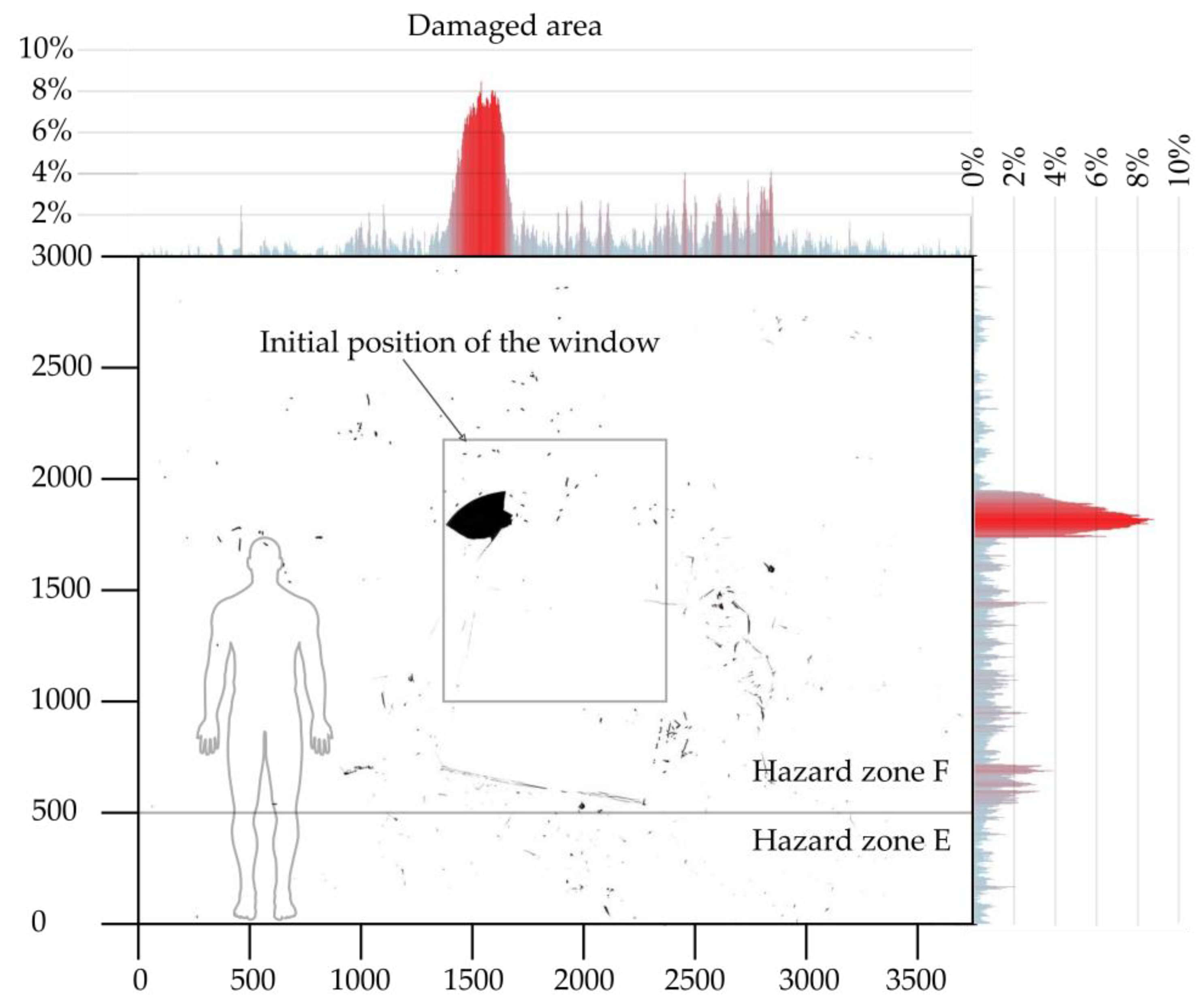
Figure 15 shows the analyzed witness wall with traces of the impacting window fragments in test ASF01.
About 1.05% of the total witness wall area was damaged in the test (about 1181 cm2). Cutting marks of the impacting glass fragments were documented up to a height of about 290 cm. The impact of the sash frame is clearly visible by an ~20 cm × 20 cm punched area in the witness wall at a height of about 1.8 m above ground. The remaining relatively low density of impacts at the center of the wall indicates the impact of the ASF.
In summary, the tests on the windows with ASF-retrofitted glazing units showed that despite the presence of a retrofit measure, a high number of glass fragments impacted hazard zone F. In addition, the tests demonstrated the potential hazards posed by the torn-off window frame. If the frame impacts a person, blunt trauma or bone fractures are possible. It can be assumed that there is a high risk to individuals due to the combination of sharp glass fragments and heavy hard frame fragments.
3.3. Windows Retrofitted with ASFs and Caught by a CCS
In the tests CC01 to CC06, the windows were equipped with ASFs, and the fragments are caught by various catcher-cable systems (CCSs). Tests CC01 to CC04 were conducted with a soft CCS configuration (
Table 2) and CC05 and CC06 with a hard CCS configuration. In addition, the window frames in tests CC03 and CC04 were equipped with steel profiles, while in the remaining test, no steel profiles were installed (
Table 1). During test CC01, the ASF was cut along the bare steel cables. Hence, for all remaining five tests, the cables were sheathed with flexible pPVC tubes. This has proven to be effective in preventing cutting.
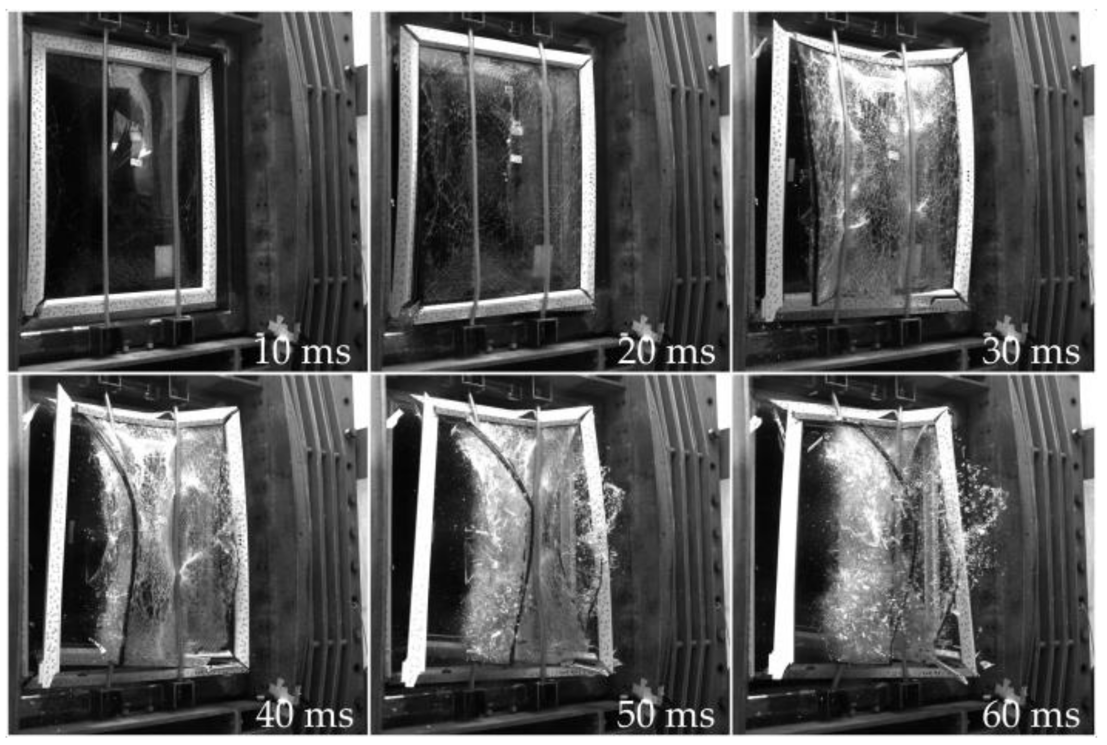
Figure 16 shows the high-speed video recordings of test CC02 over a period of 10 ms to 60 ms. As in the previous tests, the sash was torn off from the frame. However, the trajectory of the torn-off window sash was abruptly stopped by the CCS at about 16 ms. During the impact, the ASF was fully detached from the sash frame and wrapped around the two cables (at about 40 ms). On the one hand, the sash frame and the ASF are retained by the CCS. On the other hand, the glass fragments of the non-retrofitted pane are not retained by the cables, as can be seen at about 50 ms. They are propelled further towards the protected area (
Figure 16, 60 ms). Similar mechanisms to those described above were observed in the other five tests with CCSs.
In summary, the CCS can effectively stop the heavy window frames and the ASF. Regardless, hazardous glass fragments can still fly into the protected area.
3.3.1. Displacements and Velocities of the Fragments, and Cable Forces
Figure 17a shows the measured displacement–time and velocity–time histories in test CC02 at the center of the glazing and at the sash frame. In test CC02, a soft CCS configuration was used. Impact velocities in the six tests ranged from 6 m/s to 15 m/s. The resulting force–time histories in the cables S1 and S2 are shown in
Figure 17b.
The impact time
at about 16 ms (
Figure 17a) can be correlated with the initial increase in tensile forces in the cables, at about 16 ms (
Figure 17b). At the same time, it marks the onset of the velocity decay of the sash frame (
Figure 17a). The velocity at the center of the glazing was abruptly reduced shortly after reaching the maximum cable force F
max (at about 26 ms), correlating with the unloading of the CCS. This verifies the measurements since cable tensile force and the deflection are directly related. Similar effects were observed in the remaining five CCS tests.
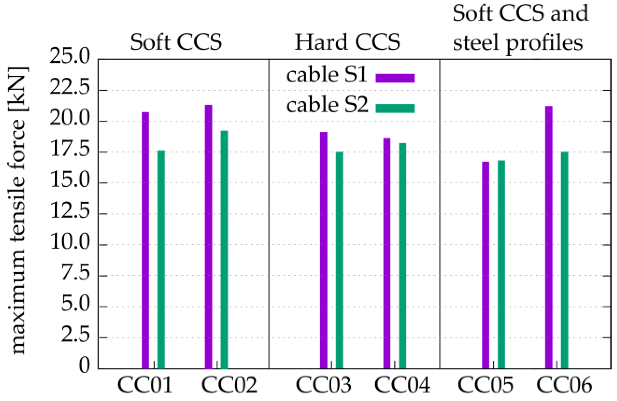
Figure 18 depicts the measured maximum cable forces
in each test. Cable S1 is located at the outer left side of the window (
Figure 16). It tends to be generally subjected to slightly higher forces than the cable S2. This effect might be due to a slightly asymmetric impact of the sash on the CCS.
No significant differences can be observed between the response of the tested soft and hard CCS systems. Most importantly, the cables did not fail in any of the six tests.
3.3.2. Hazard Level
In all six tests, the sash frame was retained by the CCS. Similarly, the ASFs were retained, except for test CC01, where the ASF experienced a cut-through failure. However, in all tests, the glass fragments from the non-retrofitted glass pane on the attacked side of the window were not stopped and were propelled into the protected area. Consequently, the used retrofit measures were not able to reduce the hazard to personnel sufficiently. All six CCS tests resulted in hazard rating F according to ISO 16934:2007 [
27]. About 0.06% to 0.35% of the witness wall area was damaged in the tests.
3.4. Effectivness of the Blast Protection Measures
In summary, all 10 conducted tests resulted in hazard level F according to ISO 16934:2007 [
27]. Since hazard level F is associated with a high hazard, the retrofit measures applied did not sufficiently reduce the hazard to people in the protected area.
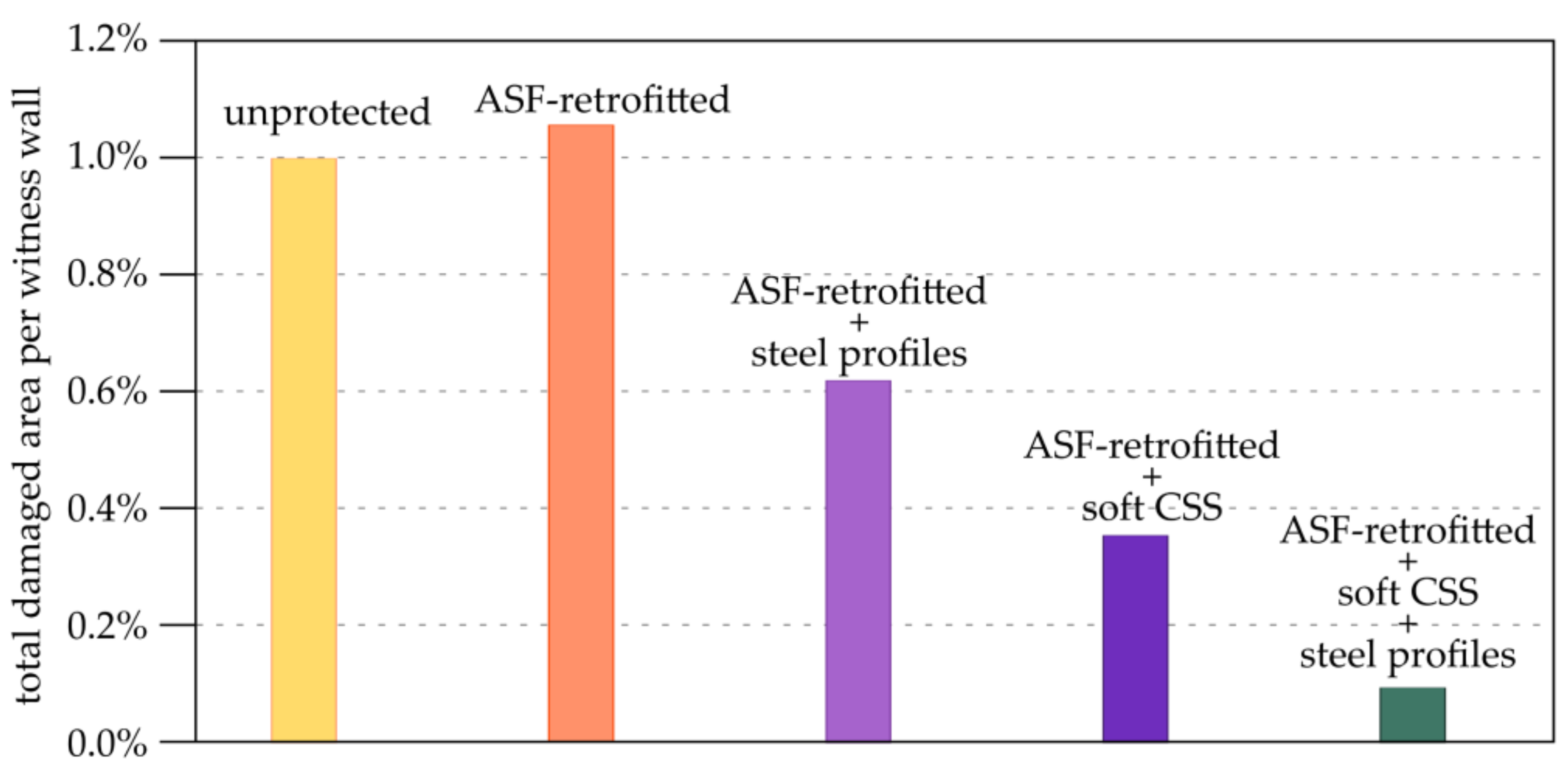
Nevertheless, when comparing the different sets of protective measures, a significant improvement in protection can be observed. As a benchmark for this improvement, the damaged area of the witness wall evaluated through the optical analysis can be used.
Figure 19 shows the percentage of the total witness wall area damaged in each test.
The following results are obtained:
Unprotected window: About 0.99% of the total witness wall area sustained damage solely by impacting glass fragments. It is important to note that in this test, the torn-off sash frame was retained by a wooden support beam deployed for the laser rangefinders. If the sash frame had also impacted the witness wall, the damaged area would likely have been much greater.
Window retrofitted with ASF: About 1.05% of the total witness wall area sustained damage in the test with no steel profiles fitted in the window frames. The impact of the sash frames punched a hole into the witness walls. This displays the severe hazard posed by propelled parts of the window frame.
Window frame with steel profiles, retrofitted with ASF: In the test using steel profiles fitted into the window frames, the damaged area was reduced by about 41% compared to the test without steel profiles. The frame and the glass fragments still impacted the witness wall.
Window retrofitted with ASF and CCS: Generally, the CCS was able to catch the window frame and the ASF; however, some glass fragments were still propelled into the protected area, they mostly originated from the un-retrofitted pane. In the test, 0.35% of the area of the witness wall was damaged using an ASF and a soft CCS. Compared to the test configuration without a CCS, a reduction of about 66% of the damaged area was achieved.
Window frame with steel profiles, retrofitted with ASF and CCS: The tests incorporating an ASF, a soft CCS, and steel profiles fitted into the window frames yielded the lowest percentage of damaged area (0.06%). This marks a remarkable reduction in the damaged area, approximately 94%, compared to an unprotected window.
4. Practical Considerations Using Catcher-Cable Systems
The test series generally demonstrated that retrofitting conventional uPVC windows with a combination of anti-shatter films (ASFs) and catcher-cable systems (CCSs) offers only limited protection against ER1 blast loads. This suggests that such protective measures should only be employed with careful risk considerations, e.g., as a temporary solution. In certain situations, it might be more practical to additionally strengthen the window frame and to implement advanced anchorage for the ASF, such as mechanical anchorage [
22]. For new buildings, more efficient protective measures, such as blast-resistant security windows, should be implemented.
When considering catcher-cable systems (CCSs) as a protective measure, it is crucial to take into account several aspects:
The CCS will only be efficient if it is used in combination with an anti-shatter film (ASF) attached to the glazing of the window.
In cases where an insulating glazing unit is retrofitted, the ASF should be applied on both panes, at the attacked and protected side, to prevent the uncontrolled flight of glass fragments.
To prevent the window sash from sliding past them, a minimum of two cables should be utilized. This recommendation is also outlined in [
32].
The cables should be distributed evenly, considering the mass distribution and the expected trajectory of the fragments.
To prevent cutting of the ASF, it is important to coat or sheath the bare steel cable with soft polymers and to ensure a minimum diameter.
Note that during the conducted test CC01, the impact on the bare steel cables resulted in the cutting of the ASF. Subsequently, for all remaining tests, the cables were sheathed with flexible pPVC tubes. This has proven to be effective in preventing cutting.
4.1. Calculating Cable Forces
The conducted test series showed that the catcher-cables were subjected to an impact load, rather than to a blast load. This statement becomes clear when comparing the average duration of the overpressure phase, which was 18.3 ms (
Figure 5), with the onset of the cable tensile forces at around 16.5 ms (
Figure 17b). In our case, the scenario might therefore be simplified as a pure impact scenario, without considering air blast effects. It should be noted that this consideration is only valid for the tested configuration. However, in other blast scenarios, with significantly longer overpressure phases (e.g., gas explosions), the blast loads may additionally affect the cable forces.
The impact scenario is defined by the mass, velocity, and rigidity of the impacting window sash. The following sequence of the impact was observed from the high-speed videos:
- (a)
The relatively rigid sash frame acts on the CCS in the immediate vicinity of the anchorages (
Figure 20a). The cable deflects particularly at these impact locations.
- (b)
The soft anti-shatter film with adhering glass fragments acts on larger areas of the catcher-cable system (
Figure 20b). The film adapts to the cable accordingly.
Numerous analytical solutions of a cable system under static loading can be found in the literature, e.g., in Petersen [
33]. However, the impact of the window sash represents a dynamic loading, incorporating effects, such as mass inertia. Analytical calculations might be conducted by utilizing a single degree of freedom system (e.g., [
34]). Here, non-linear approaches become essential to consider cable and spring deformations. Furthermore, it is crucial to determine a suitable force–time history that accurately represents the impact of the window sash. This force–time history varies depending on the rigidity of both the impacting window sash and the catcher-cable system.
Given these complexities, an analytical approach proves cumbersome. Numerical simulations utilizing a detailed finite element model of the window may provide a more effective solution to overcome these challenges [
35].
4.2. Anchoring of the Cables to Supporting Structures
Securely anchoring the CCS in the supporting structure can be challenging. In the conducted tests series, the maximum tensile force within the cables was around 21.5 kN. If the supporting structure cannot withstand these anchoring forces, the CCS is at risk of failure, potentially posing a hazard itself. It should be stressed that in this test series, a CCS anchored with a spring-supported bearing was used. Without such spring elements, cable tension forces are expected to be even higher since fewer deformations are possible.
Vertical anchoring of the cables can be achieved in both the floor and ceiling, while horizontal anchoring is possible between the window reveals. Optimal anchoring conditions can be found in reinforced concrete, as masonry proves to be a comparatively weak support. Due to the significant forces involved, anchoring in wooden support structures is often inappropriate. For masonry and wood, the most effective solution for anchoring cables is probably to use counter plates on the opposite side of the structure along with threaded rods. If the maximum allowable forces are exceeded, another possible solution may be to increase the number of cables.
Note that using bending-resistant steel pipe structures (i.e., catcher-bar systems) might reduce the issues with anchoring and avoid the cutting effects of the ASF at the same time. Regardless, this was not within the scope of the study presented here.
4.3. Limitations for the Use of Anti-Shatter Films and Cable-Catcher Systems
In the test series presented here, the retrofitted protective measures were examined at specific blast loads, with a specific window size, window type, type of anti-shatter film, type of cable, type of cable anchorage, etc. Below, potential limitations and scalability of the tested protective measures are discussed.
Most importantly, it is crucial to know how the selected anti-shatter film has been certified. For instance, the ASFs applied in this test series were certified according to the EN 13541:2012 [
10] test method against an ER1 blast load. This certification test method requires the dimensions of the glazing to be 1100 mm × 900 mm. Consequently, this also considerably limits the possible window size. Moreover, in the EN 13541:2012 [
10] test method, the edges of the glazing are clamped into a stiff test frame. This type of clamping is nearly impossible to implement in a standard window frame. Consequently, the possible protective effectiveness achieved in certification tests of glazing units and real window glazing can significantly differ.
One significant limitation of cable-catcher systems is the anchoring of cable forces to adjacent structural components. As the cable span increases, the forces quickly reach levels that can no longer be secured, unless a large number of cables are used, which is also not favorable.
Generally, due to the highly nonlinear behavior of the tested window type and retrofitted protective measures, the test results can only be transferred to a very limited extent to other dimensions. To expand this scope, numerical simulations can be used.
It is expected that the measures are more suitable for rather small window dimensions and moderate blast loads (below ER1). For blast loads with a higher intensity and larger window dimensions, replacement with blast-resistant windows is advisable. However, the protective design needs to be assessed individually.
5. Summary and Conclusions
In the event of an explosion, conventional unprotected windows can pose a particularly high risk of injury to occupants as glass fragments and window frames are propelled both inside and outside a building. This article explored the effectiveness of various protective measures for conventional single casement windows against blast. The results of 10 shock-tube tests were presented, analyzed, and discussed. Subjected to an ER1-blast load, the retrofit measures for the windows include anti-shatter films (ASFs) and catcher-cable systems (CCSs). A range of measurement methods, including digital image correlation and force transducers, was utilized to capture the velocity of window fragments and measure the cable forces. Additionally, an optical method for hazard evaluation was suggested and implemented to assess the impact of fragments on a witness wall.
In all 10 tests, the windows experienced failure, and the window sashes were propelled towards the protected area. Here, the effectiveness of the CCS was demonstrated, as they successfully caught the sash frame and the anti-shatter film along with adhering glass fragments. Note that even though the CCS caught the heavy frame parts of the window, several glass fragments were still thrown into the protected area. More severely, without a CCS, the frames were propelled 3 m into the protected area, where they impacted against a witness wall. The measured average velocity of the fragments was about 10 m/s. Caught by the CCS, the maximum measured tensile force within the cables was around 21.5 kN.
When analyzing the witness wall, it can be concluded that despite the presence of retrofit measures, an unacceptable hazard rating of F (high hazard) according to ISO 16934:2007 [
27] was consistently reached. Nevertheless, when comparing the different sets of protective measures, a significant improvement in protection can be observed. Compared to the results with an unprotected window, a window with a combination of ASF, CCS, and steel profiles fitted into the frame profiles remarkably lowered the hazard. With this combination, the damaged witness wall area was reduced by approximately 94%. It should be stressed that the CCS was particularly effective in mitigating the flight of the heavy frame fragments, which can cause blunt trauma and bone fractures.
Despite the lack of acceptable hazard reduction, the results of the experiments provided important information for the design of catcher-cable systems. To underline this, the results presented in this article are supplemented by practical considerations using catcher-cable systems. Finally, it should be noted that retrofit measures need to be tested on full window systems. This approach will provide detailed information on blast-resistance in practical applications. Retrofitting only one component of a window, such as glazing, is often not sufficient because the weakest link in the chain determines performance.
For future studies, the following research and development potential for anti-shatter films (ASFs) and catcher-cable systems (CCSs) can be recognized:
Improving the attachment of the protective films to the window frames: In the tests conducted, the ASF was installed in a “daylight” application, meaning that the films are simply placed under the glazing beads without any attachment to the window sash. However, in the event of glass breakage, the films must be attached to the sash in order to create a membrane effect. In the tests conducted, this was not the case, resulting in the film being torn off from the sash, especially after the impact on the CCS. In future tests, the ASF could be bonded or mechanically attached to the sash.
Testing flexible cables: In the tests conducted, relatively stiff steel cables were anchored using simple elastic springs. This technique allowed for greater cable deflections than a fixed anchorage. Future tests may include catcher-cables made of more stretchable synthetic materials (nylon or polyamide) or a combination of natural and synthetic fibers.
Testing energy-absorbing anchoring techniques: Energy-absorbing effects, e.g., from plastic deformation, played a minor role in the tested CCS. However, it is well known from impact tests [
15] that an energy-absorbing anchorage of the cable can also significantly reduce the cable forces. In future tests, such techniques can be tested, e.g., by simply anchoring the cables to deformable steel plates.
Author Contributions
Conceptualization, M.A., J.D.v.d.W., M.W., A.P. and N.G.; methodology, M.A., J.D.v.d.W. and N.G.; investigation, M.A. and J.D.v.d.W.; formal analysis, M.A., J.D.v.d.W., M.W. and A.P.; writing—original draft preparation, M.A. and J.D.v.d.W.; writing—review and editing, M.W., A.P. and N.G.; visualization, M.A.; supervision, N.G.; project administration, M.A.; funding acquisition, M.A. and N.G. All authors have read and agreed to the published version of the manuscript.
Funding
This research was funded by the Federal Office of Civil Protection and Disaster Assistance (BBK), Department II.5, in Germany (grant number BA2533). The support is gratefully acknowledged.
Data Availability Statement
The raw data supporting the conclusions of this article will be made available by the authors on request.
Conflicts of Interest
The authors declare no conflicts of interest. The funders had no role in the design of the study; in the collection, analyses, or interpretation of data; in the writing of the manuscript; or in the decision to publish the results.
References
- Remennikov, A.; Carolan, D. High Performance Retrofit Solutions for Blast Protection of Facades in Office Buildings. In Proceedings of the RNSA Security Technology Conference, Melbourne, Australia, 28 September 2007. [Google Scholar]
- Fletcher, E.R.; Richmond, D.R.; Jones, R.K. Air Blast Effects on Windows in Buildings and Automobiles on the Eskimo II Event. In Proceedings of the Minutes of 15th Explosives Safety Seminar—Volume I, San Francisco, CA, USA, 18–20 September 1973. [Google Scholar]
- Fletcher, E.R.; Richmond, D.R.; Yelverton, J.T. Glass Fragment Hazard from Windows Broken by Airblast; Lovelace Biomedical and Enviromental Research Inst.: Albuquerque, NM, USA, 1980. [Google Scholar]
- CPNI. Guidance Note: Use of Anti-Shatter Film (ASF) and Bomb Blast Net Curtains (BBNC); Centre for the Protection of National Infrastructure: London, UK, 2013.
- CPNI. Guidance Note: Peel Adhesion Testing of Anti-Shatter Film; Centre for the Protection of National Infrastructure: London, UK, 2013.
- National Urban Security Technology Laboratory. Shatter-Resistant Window Film Market Survey Report: System Assessment and Validation for Emergency Responders; Department of Homeland Security: New York, NY, USA, 2015.
- Memari, A.M.; Behr, R.A.; Kremer, P.A. Dynamic Racking Crescendo Tests on Architectural Glass Fitted with Anchored Pet Film. J. Archit. Eng. 2004, 10, 5–14. [Google Scholar] [CrossRef]
- CPNI. Guidance Note: Specifying Anti Shatter Film as a Blas Mitigation Measure (Daylight Application); Centre for the Protection of National Infrastructure: London, UK, 2013.
- Mattei, S.; Cozzarini, L.; Bedon, C. Pre- and Post-Failure Experimental Bending Analysis of Glass Elements Coated by Aged Anti-Shatter Safety Films. In Proceedings of the 8th Challenging Glass Conference, Ghent, Belgium, 20 June 2022. [Google Scholar] [CrossRef]
- EN 13541:2012-06; Glass in Building—Security Glazing—Testing and Classification of Resistance against Explosion Pressure. Beuth Verlag GmbH: Berlin, Germany, 2012.
- Bedon, C.; Kevin, C.; Doormaal, A.; Haberacker, C.; Hüsken, G.; Larcher, M.; Saarenheimo, A.; Solomos, G.; Stolz, A.; Thamie, L.; et al. JRC94930—A Comparison of Existing Standards for Testing Blast Resistant Glazing and Windows; Publications Office of the European Union: Luxembourg, 2014. [Google Scholar]
- Dogruel, S.; Field, C. Design and Testing of Cable Catchment Systems for Historic Window Blast Protection. In Proceedings of the Structures Congress 2011, Las Vegas, NE, USA, 14–16 April 2011; pp. 1359–1374. [Google Scholar]
- GSA-TS01-2003; Standard Test Method for Glazing and Window Systems Subject to Dynamic Overpressure Loadings. US General Services Administration: Washington, DC, USA, 2003.
- Sisson, T.; Montalva, A. Mitigation of Glass Hazards in High Threat Environment Using Cable Catch Systems. In Proceedings of the Structures Congress 2019, Orlando, FL, USA, 24–27 April 2019; pp. 182–192. [Google Scholar]
- Remennikov, A.; Brodie, L.S. Experimental Investigation of Cable Catcher Systems for Office Building Blast Protection. In Proceedings of the Australasian Structural Engineering Conference (ASEC2012), Perth, Australia, 28 November–2 December 2012; Engineers Australia: Barton, Australia, 2012; pp. 1–8. [Google Scholar]
- Bedon, C.; Amadio, C. Exploratory Numerical Analysis of Two-Way Straight Cable-Net Façades Subjected to Air Blast Loads. Eng. Struct. 2014, 79, 276–289. [Google Scholar] [CrossRef]
- Teich, M.; Warnstedt, P.; Gebbeken, N. Influence of Negative Phase Loading on Cable Net Facade Response. J. Archit. Eng. 2012, 18, 276–284. [Google Scholar] [CrossRef]
- Brewer, T.R.; Morrill, K.B.; Crawford, J.E. A New Kind of Blast-Resistant Curtain Wall Façade. Int. J. Prot. Struct. 2015, 6, 671–689. [Google Scholar] [CrossRef]
- Lan, S.; Crawford, J.E. Numerical Simulation of Blast Response of a Cable Catcher System for Glazing Facade. In Proceedings of the 10th International Conference on Shock & Impact Loads on Structures, Singapore, 25–26 November 2013. [Google Scholar]
- Millon, O.; Haberacker, C. Analyse und Vergleich von Prüfnormen und Prüfverfahren für Glasfassaden unter extremer Einwirkung. In Proceedings of the Bau-Protect 2016: 7. Workshop Bau-Protect: Tagungsband, Freiburg, Germany, 15–16 November 2016; Hiermaier, S., Gebbeken, N., Klaus, M., Stolz, A., Eds.; Fraunhofer Verlag: Stuttgart, Germany, 2017; pp. 301–316. [Google Scholar]
- DIN EN 1627:2021-11; Pedestrian Doorsets, Windows, Curtain Walling, Grilles and Shutters—Burglar Resistance—Requirements and Classification. Beuth Verlag GmbH: Berlin, Germany, 2021.
- Remennikov, A.; Chipperfield, L.; McInerney, N. Experimental Investigation of Load-Deformation Response for Blast-Resistant Facade Glazing Solutions. In Proceedings of the Australasian Structural Engineering Conference (ASEC), Melbourne, Australia, 26–27 June 2008; The Meeting Planners: Melbourne, Australia, 2008. [Google Scholar]
- Performance Specifications of the Piezoresistive Pressure Transducer—Model Endevco Model 8510C-15. Available online: https://buy.endevco.com/ContentStore/mktg/Downloads/EDV-DS-8510C.pdf (accessed on 26 February 2024).
- Stewart, M.G.; Netherton, M.D.; Baldacchino, H. Observed Airblast Variability and Model Error from Repeatable Explosive Field Trials. Int. J. Prot. Struct. 2020, 11, 235–257. [Google Scholar] [CrossRef]
- Gan, E.C.J.; Remennikov, A.; Ritzel, D.; Uy, B. Approximating a Far-Field Blast Environment in an Advanced Blast Simulator for Explosion Resistance Testing. Int. J. Prot. Struct. 2020, 11, 468–493. [Google Scholar] [CrossRef]
- Schneider, J.; Von Ramin, M.; Stottmeister, A.; Stolz, A. Characterization of Debris Throw from Masonry Wall Sections Subjected to Blast. Eng. Struct. 2019, 203, 109729. [Google Scholar] [CrossRef]
- ISO 16934:2007; Glass in Building—Explosion-Resistant Security Glazing—Test and Classification by Shock-Tube Loading. International Organization for Standardization: Geneva, Switzerland, 2007.
- Dorafshan, S.; Maguire, M.; Qi, X. Automatic Surface Crack Detection in Concrete Structures Using OTSU Thresholding and Morphological Operations; Utah State University: Logan, UT, USA, 2016. [Google Scholar]
- Bilateral Filtering for Gray and Color Images. Available online: https://homepages.inf.ed.ac.uk/rbf/CVonline/LOCAL_COPIES/MANDUCHI1/Bilateral_Filtering.html (accessed on 2 June 2021).
- Canny Edge Detection. Available online: https://docs.opencv.org/master/da/d22/tutorial_py_canny.html (accessed on 2 June 2021).
- Eroding and Dilating. Available online: https://docs.opencv.org/3.4/db/df6/tutorial_erosion_dilatation.html (accessed on 2 June 2021).
- UN Department of Safety and Security. Physical Security Unit Information Bulletin No. 11 Annex A-2: SRF and Cable Catchers; UNDSS: New York, NY, USA, 2021. [Google Scholar]
- Petersen, C. Stahlbau, 3rd ed.; Friedr. Vieweg & Sohn Verlagsgesellschaft mbH: Braunschweig, Germany; Wiesbaden, Germany, 1993. [Google Scholar]
- Biggs, J.M. Introduction to Structural Dynamics; McGraw-Hill Book Company: New York, NY, USA, 1964. [Google Scholar]
- Andrae, M.; van der Woerd, J.D.; Wagner, M.; Pietzsch, A.; Gebbeken, N. Betrachtungen zum Tragverhalten von Seilauffangsystemen zur Gefahrenabwehr für Fenster unter Luftstoßwellenbeanspruchung. In Proceedings of the Berichte der Fachtagung Baustatik—Baupraxis 15, Hamburg, Germany, 4–5 March 2024; Oesterle, B., Bögle, A., Striefler, L., Eds.; Institut für Baustatik, Technische Universität Hamburg: Hamburg, Germany, 2024. [Google Scholar]
Figure 1.
Tested conventional single-sash window with an insulating glazing unit; (a) front view and (b) cross section of the window.
Figure 1.
Tested conventional single-sash window with an insulating glazing unit; (a) front view and (b) cross section of the window.
Figure 2.
Arrangement of the fitting system.
Figure 2.
Arrangement of the fitting system.
Figure 3.
Tested window mounted to the adapter frame at the shock-tube; (a) front view on the shock-tube and (b) anchors of the window and bearings for the CCS.
Figure 3.
Tested window mounted to the adapter frame at the shock-tube; (a) front view on the shock-tube and (b) anchors of the window and bearings for the CCS.
Figure 4.
(a) Installed catcher-cables; anchoring (b) at bearing A and (c) at bearing B.
Figure 4.
(a) Installed catcher-cables; anchoring (b) at bearing A and (c) at bearing B.
Figure 5.
Measured reflected overpressure−time history in test ASF01.
Figure 5.
Measured reflected overpressure−time history in test ASF01.
Figure 6.
According to ISO 16934:2007 [
27], (
a) hazard zones and (
b) hazard rating.
Figure 6.
According to ISO 16934:2007 [
27], (
a) hazard zones and (
b) hazard rating.
Figure 7.
(a) Digitally aligned and cropped image of a witness panel, and (b) binary representation of a witness panel.
Figure 7.
(a) Digitally aligned and cropped image of a witness panel, and (b) binary representation of a witness panel.
Figure 8.
High-speed video recordings of the unprotected configuration in test U1.
Figure 8.
High-speed video recordings of the unprotected configuration in test U1.
Figure 9.
Failure mode at the frame corner; (a) high-speed video at 15 ms, (b) original unloaded condition, and (c) deformed window under the blast load.
Figure 9.
Failure mode at the frame corner; (a) high-speed video at 15 ms, (b) original unloaded condition, and (c) deformed window under the blast load.
Figure 10.
Possible failure mechanism of the fitting system.
Figure 10.
Possible failure mechanism of the fitting system.
Figure 11.
Measured displacements and velocities in the test with an unprotected window (U1).
Figure 11.
Measured displacements and velocities in the test with an unprotected window (U1).
Figure 12.
Analyzed witness wall with impact damages after test U1.
Figure 12.
Analyzed witness wall with impact damages after test U1.
Figure 13.
High-speed video recordings of the protected ASF-retrofitted configurations.
Figure 13.
High-speed video recordings of the protected ASF-retrofitted configurations.
Figure 14.
Measured displacement and velocity of the sash in test ASF01.
Figure 14.
Measured displacement and velocity of the sash in test ASF01.
Figure 15.
Analyzed witness wall with impact damages after test ASF01.
Figure 15.
Analyzed witness wall with impact damages after test ASF01.
Figure 16.
High-speed video recordings of test CC02 with a soft CCS configuration.
Figure 16.
High-speed video recordings of test CC02 with a soft CCS configuration.
Figure 17.
(a) Measured displacement and velocity of the sash in test CC02; (b) measured tensile forces in test CC01 and CC02 conducted with a soft CCS−configuration.
Figure 17.
(a) Measured displacement and velocity of the sash in test CC02; (b) measured tensile forces in test CC01 and CC02 conducted with a soft CCS−configuration.
Figure 18.
Maximum tensile forces measured in the catcher-cable systems.
Figure 18.
Maximum tensile forces measured in the catcher-cable systems.
Figure 19.
Total damaged area of the witness wall.
Figure 19.
Total damaged area of the witness wall.
Figure 20.
Impact on the catcher-cable system: (a) window sash; (b) glazing with ASF.
Figure 20.
Impact on the catcher-cable system: (a) window sash; (b) glazing with ASF.
Table 1.
Overview of test configurations of the tested windows.
Table 1.
Overview of test configurations of the tested windows.
| Test | Configuration | ASF | Steel Profiles | CCS |
|---|
| U1 | Basic unprotected | - | - | - |
| ASF01 | ASF-retrofitted | yes | - | - |
| ASF02 | yes | - | - |
| ASF03 | yes | yes | - |
| CC01 | ASF-retrofitted including CCS | yes | - | yes (soft) |
| CC02 | yes | - | yes (soft) |
| CC03 | yes | yes | yes (soft) |
| CC04 | yes | yes | yes (soft) |
| CC05 | yes | - | yes (hard) |
| CC06 | yes | - | yes (hard) |
Table 2.
Mechanical properties of the tested catcher-cable systems.
Table 2.
Mechanical properties of the tested catcher-cable systems.
| Configuration | Test | Cable Diameter [mm] | Static Ultimate Tensile Strength [kN] | Spring Stiffness [N/mm] |
|---|
| Soft | CC01, CC02, CC03, CC04 | 8 | 21.84 | 71 |
| Hard | CC05, CC06 | 10 | 32.19 | 186 |
Table 3.
Mean intensity of the measured blast loads from the 10 shock-tube tests.
Table 3.
Mean intensity of the measured blast loads from the 10 shock-tube tests.
| | Reflected Peak Overpressure [kPa] | Reflected Maximum Impulse [kPa∙ms] | Duration of the
Positive Pressure Phase [ms] |
|---|
| Mean value | 66.7 | 417.7 | 18.3 |
| Coefficient of variation | 3.2% | 4.6% | 3.8% |
| Disclaimer/Publisher’s Note: The statements, opinions and data contained in all publications are solely those of the individual author(s) and contributor(s) and not of MDPI and/or the editor(s). MDPI and/or the editor(s) disclaim responsibility for any injury to people or property resulting from any ideas, methods, instructions or products referred to in the content. |
© 2024 by the authors. Licensee MDPI, Basel, Switzerland. This article is an open access article distributed under the terms and conditions of the Creative Commons Attribution (CC BY) license (https://creativecommons.org/licenses/by/4.0/).


 ,
, 


