Abstract
This manuscript attempts to classify typical errors occurring during the design, production, and use of prefabricated and prestressed concrete girders and slabs manufactured in Poland for industrial buildings since the 1950s. Although the cases discussed concern Poland, most of them have a universal character, and as such are also found in other countries. The defects and errors are illustrated with examples and the causes of their occurrence are also discussed. A method of classifying flaws based on the period of their occurrence was proposed. Most of the examples discussed were encountered by the authors during their professional work. In most of the presented cases, repair was possible, enabling further safe operation. This paper shows how important it is to periodically check the technical condition of prestressed structures and how common and at the same time trivial mistakes may be made by designers and contractors of this type of structure, despite the experience of over 70 years of their mass use. The quality of modern prestressed structures is undoubtedly higher. Using the experience of previous generations, designers and contractors abandoned the less durable post-tensioned concrete lattice girders. Errors, if they appear, are most often at the stage of implementing new products or are the result of poor workmanship or disregard for unfavorable weather conditions.
1. Introduction
The concept of prestressed concrete arose almost simultaneously in the late 1880s in Europe and the United States, when Jackson and Deuring patented their concepts for prestressing slab vaults and slabs [1]. In practice, these solutions lacked durability, mainly due to the poorly understood properties of the steel used. Further acceleration of the development of the concept of concrete prestressing became possible thanks to Freyssinet’s research in the third decade of the 20th century. The practical development of the prestressing concept became a fact in the next decade, preceding the outbreak of World War II. Preparations for the war forced the Germans to save steel and at the same time choose concrete as the main construction material [2]. In occupied Poland, the first prestressed structures were ceiling beams in a fortress built by the Germans in 1941.
The end of the 1940s is considered the beginning of modern concrete construction. At the same time, it is a period of dynamic development of prestressed structures, which is related to the need to rebuild infrastructure destroyed by war. Initially, mainly bridges were prestressed [3], but in the early 1950s this technology was extended to industrial construction. This resulted in the birth in 1951 of the currently most popular cross-sections of prestressed elements. In North America, Edwards and Zia designed the first double T slab [4], and the Spancrete company began producing long and hollow core floor slabs based on Shafer’s patent [5].
In the same years, the manufacturing of precast prestressed units, initially made of pre-tensioned concrete, and later also made of post-tensioned concrete, began in Poland. These were mainly bridge beams and roof girders with spans of up to 18 m. The dominant feature of construction at that time was standardization. Centralized design allowed engineers to improve the concept and refine the technology. Thanks to this, any conceptual defects were eliminated quite quickly.
During the mass construction period that began in the 1960s, quality control requirements were less stringent than today [6]. Digitalization was also not available in the construction industry at that time. Despite this, many buildings have survived to this day in good technical condition, even though many of them have already passed their intended service life. Of course, due to age, the probability of revealing hidden defects becomes greater. They also increasingly require various types of renovations and repairs.
The 1970s are sometimes called the Lightweight and Long-span Period [7]. It was characterized by increasing the span of precast prefabricated elements and introducing hybrid structures and lightweight concrete. In Poland, the licensed production of hollow core slabs and TT slabs began at this time. The design and manufacturing of prestressed elements were still centralized. Pretensioned concrete girders with a span of 24 m were introduced. Only heavy concrete roof and wall coverings were used. Light-covering systems appeared in the 1980s. During this period, precast construction and the entire economy began to experience a huge crisis. Many plants went bankrupt.
The end of the 1990s was a revival, but also a revolution of the Polish precast concrete industry. International corporations appeared and introduced their own technologies and product ranges. Few domestic producers tried to adapt to new technologies and requirements. Today the modern market of prestressed precast elements includes not only industrial construction (roof girders and ceiling slabs) but also infrastructure construction (bridge beams, railway sleepers, utility poles). The variety of elements used in small-scale construction (ribbed ceilings, slab ceilings, lintel beams) and in completely new applications resulting from the current needs of the economy (e.g., supporting structures for photovoltaic panels) is growing.
Nowadays, some precasted prestressed concrete structures are already 70 years old and have exceeded the originally planned durability period. They owe their good state mainly to the care of users who regularly inspect their technical condition. Defects revealed during such reviews were repaired on an ongoing basis. Some cases of damage discussed in this manuscript were discovered by the authors during such reviews. However, the dominant examples are failure states that were found during the production, assembly, or technical acceptance of buildings. All described cases and most of the presented photos come from the authors’ expert works. They illustrate the most common, but also less typical, examples of errors made by designers, manufacturers, and users of prestressed concrete structures. It is estimated that as many as 17% of structure failures are caused during the construction phase due to human errors [6,8].
This manuscript discusses examples of defects and damage occurring in precast pre-tensioned and post-tensioned industrial structures manufactured since the mid-20th century. The cases discussed concern Poland; however, most of these defects are universal and can also be found in other countries, as illustrated by the cited literature. The described defects revealed at various stages of the structure’s life; therefore, the following classification was proposed:
- defects and errors occurring during design (including incorrect geometry, invalid static scheme, construction of details, and reinforcement),
- defects and errors occurring during production (including shape, material, reinforcement, and prestressing technology),
- defects and errors occurring during construction (including transport and assembly weather conditions),
- defects occurring during usage (including use, durability, and renovations).
Understanding the cause and the period in which the defect occurred is important for the planned repair methods. Revealing many design errors is impossible without analyzing the documentation. They are also usually more difficult to remove and may involve mass-produced units. Utilization errors are most often easy to fix unless they are discovered very late. The summary provided briefly presents the frequency of finding the most typical defects and the methods of repairing or mitigating them.
2. Defects and Errors Occurring during Design
The most trivial design errors involve underestimating loads or obvious calculation errors, resulting in insufficient load-bearing capacity or stiffness of structural elements. Fortunately, most of such mistakes become visible already at the production or assembly stage, and the defective elements are replaced.
2.1. Incorrect Geometry in Modular Systems
In the first period of development of prefabrication of concrete structures in Poland, there were no detailed guidelines, including standards. Thus, most of the projects were based on the experience and technical intuition of their creators. A quite common mistake, resulting mainly from low quality of workmanship, was the use of an inappropriate (too short or too long) support length of roof girder, as well as the direct support by a high set of metal sheets or too thick leveling grout. This led to harmful stress concentrations in elements not designed to transfer them. Moreover, if the girders were placed too deep in adjacent bays, the support zones of subsequent elements arranged in one line collided and the anchor blocks were not properly concreted.
In modern structures, what has changed is primarily the support technology. Nowadays, permanently elastic pads or tapes are usually used. The beams are secured on the supports against horizontal movement by fixing them with dowels led from the supports. The line of dowels determines its rotation point. To ensure the required support conditions, it is important to select the correct support bearing, taking into account the expected load and support conditions. The thickness of the elastic pads should be selected so that they are not completely compressed as a result of the rotation of the supported elements. It is also important to properly shape and elastically fill the dowel holes so that they do not limit the possibility of movement, taking into account their calculated size.
Irregularities often occur in the support of roof or ceiling slabs. One of the most frequently repeated mistakes in the 1960s and 1970s resulted from the uncritical adoption of the modular axle system. This resulted in the shortening of the zones of expansion joints, and therefore in the inability to properly support the roof slabs and shape the concrete topping. The contractors were unable to fit the roof slabs between the girders and unacceptably solved this problem—usually by cutting the stirrups used to tie the concrete topping with the upper flange or by bending them as shown in Figure 1.

Figure 1.
Examples of improper support of roof slabs and, consequently, lack of concrete topping caused by improper adjustment to the modular system.
2.2. Design Scheme Incompatibile with the Structural System
Typical roof girders have always been designed and constructed as simply supported, sometimes cantilevered beams. Such a scheme requires ensuring technical freedom of rotation of both supports and freedom of movement of one of them. In the past, there were cases where the ends of girders were embedded and cast in place capping or cornice beams. That prevented their free rotation (and thus changed the design scheme), while also limiting access to the anchors. Another solution that significantly changes the design scheme of the girders is their local support with columns or walls, often encountered in cases where the way of use was changed.
Various types of “improvements” leading to a change in the structural system may be dangerous. An example is the modification of the system of the Gerber beam shown in Figure 2a to a typical independent hinged support of two girders. This seemingly trivial modification not only leads to a reduction in the support area of the girders, but also changes the way of transfer of horizontal forces into the column’s head. As a result, intense bursting of the column head has occurred, as shown in Figure 2b.
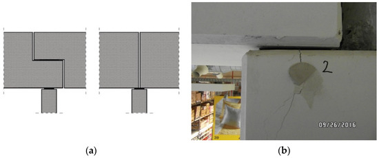
Figure 2.
Damage to the common support zone. Change in the support scheme of girders on columns: (a) support scheme; (b) damage to the column.
Another example of incompatibility with the original design is the incorrect connection of structural elements. This applies especially to expansion joints, which are necessary to minimize the effects of deformations caused by temperature or subsoil movements [9]. Too stiff assembly on dowels may prevent the beam from moving on the support, which is especially necessary for the thermal expansion joint. This applies to situations where the expansion joint is not run from the foundations, but the freedom of horizontal movements is realized at roof level. In practice, such a sliding connection requires sufficiently large dowel holes and filling them with a material with significant deformability, e.g., low-stiffness foam. Additionally, there should be support with sliding bearings [10]. The longitudinal dimension of such holes should not be less than 80 mm for typical dowels with a diameter of 20 mm. The symmetrical position of the supported beams and their precise positioning allows for a movement of approximately 30 mm; in practice, however, this is often less due to manufacturing deviations. Rigid filling of the dowel ducts prevents horizontal movement, which may cause unintended axial forces or lead to damage of the support zones, resulting in the bursting of the connected elements. Examples of purlins damaged in this way are shown in Figure 3.
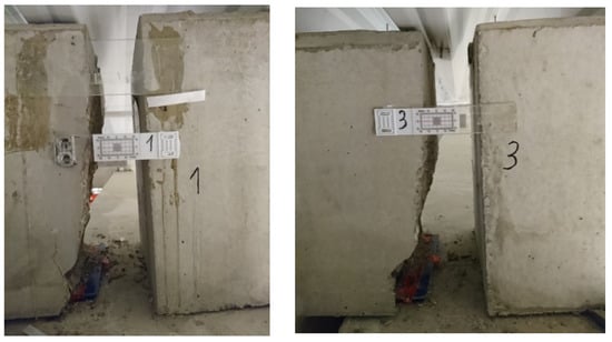
Figure 3.
Damage to the common purlin support zone in the expansion joint line.
2.3. Errors in the Construction of Details
The general geometric assumptions for prestressed elements have remained unchanged since the beginning of their production. Typically, the goal is to reduce weight by “slimming” low-strength zones, such as webs in beams. At the same time, the zones of concentration of stresses are fully or partly widened. However, unreasonable striving to optimize geometry can lead to errors. An example is locating openings in the webs of girders. They can be used to reduce the weight of beams or enable installations to be carried out in the space of roof structures. Perforated webs have already been used in long-span pretensioned concrete girders since the 1970s, but at first the openings were located in span zones where the role of the web is primarily to join the flanges. Nowadays, there is a tendency to use openings also in the support zones, where the web plays an important role in the transfer of transverse forces and the transfer of prestressing forces. In sloped girders, the height of the elements in the support zones decreases, which further reduces their load-bearing capacity. The authors have several times encountered cases of disturbing cracking of webs in the zones of openings near supports (Figure 4). The design of these openings was most often justified by the need to run the installation [11], but among the dozen or so girders damaged in this way, only one had an opening with running a sprinkler system pipe with a diameter of 25 mm. The problem found in the described cases was not the size of the openings [12], but their excessive concentration. Despite the use of strong transverse reinforcement [13,14], the transmission of diagonal forces caused by shear was disrupted, resulting in excessive narrowing of the paths of shear transfer. Additionally, numerical analyzes showed that due to the prestressing, the angle of inclination of these diagonal struts decreases by several degrees (Figure 4a), which further reduces their cross-sections that can be routed between the openings. The consequence was that the perforated girders did not meet the standard load-bearing requirements due to shear.
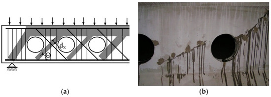
Figure 4.
Cracking of beam webs in the support zone weakened by openings: (a) scheme of the narrowing of compression struts, (b) example of damage.
Another example of over-optimization is the unjustified use of L-type spandrel beams. This solution serves to reduce the structural height of the story, allowing for the support level of the elements to be lower. Due to the eccentric support of the floor slabs, significant twists appear in the spandrel beams, causing them to rotate around the main axis [15]. Theoretically, this can be counteracted by temporarily supporting the slab units before their final tying with the spandrel beams, but this procedure generates additional costs. The consequences of excessive torsion of the spandrel beams were uneven support conditions resulting in deformation of the support pads [16] and diagonal bending of the support beams with their simultaneous torsion. These second-order forces are usually not expected to occur in the design [17]. According to the authors, when there is no technical justification, L-type beams with side support should not be used, but ordinary rectangular beams with symmetrical support should be used instead. An example of deformation within the spandrel beams is shown in Figure 5. The described twisting of the spandrel beams additionally led to incorrect support of the TT slabs. The above resulted in damage to the supporting parts of these slabs, as shown in Figure 6. If support on an L-type edge beam is necessary, the greatest possible support depth should be applied or the beam should be tied to the floor slab through tie reinforcement [18].
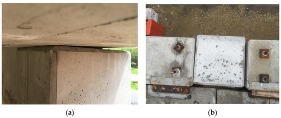
Figure 5.
Deformation of the elastomeric pad as a result of twisting the spandrel beam and the view of twisted beams (concerning the column head): (a) deformed support elastic pad, (b) twist of spandrel beams.
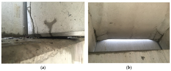
Figure 6.
Damage to the support zones of TT slabs supported on twisted spandrel beams: (a) deformed support elastic with a cracked rib end, (b) cracked connection of the rib with slab.
Excessive optimization, although sometimes justified by economic reasons, is also the use of several elements with the same geometry within one building, differing in the reinforcement used or the class of concrete. The authors encountered a case when, within one building, the designer provided several types of geometrically identical girders made of different classes of concrete and prestressed with different intensities. Unfortunately, the order of the two girders was confused during assembly, which resulted in the risk of overloading the roof structure under a heavy air conditioning unit. Fortunately, the fault was discovered at the construction stage, which made it possible to design and build a steel structure on the roof, allowing for the transfer of loads to the adjacent girders.
2.4. Incorrect Construction of Reinforcement
The fourth group of design errors is related to the incorrect shape of the reinforcement in areas with irregular shapes. In such places, the distribution of stresses (local concentration) is disturbed, often resulting in excessive cracking and reducing the load-bearing capacity.
Situations of incorrect reinforcement construction are generally frequent, and they mainly concern the support and anchoring zones of the prestressing reinforcement; i.e., zones that are difficult to reinforce due to significant concentrations and complex stress levels. This is due to typical design errors, consisting of improper reinforcement of the tendon anchoring zones. An error visible in some of the archived projects was too weak reinforcement under the cable anchors. Fortunately, such a defect usually becomes visible already during the stressing of the girders. Moreover, some designers believe that the problems of anchoring zones mainly concern post-tensioned concrete and the pressure of cable anchoring systems [19]. Although anchoring through the adhesion of tendons has a positive effect on the distribution of stresses, stress accumulations still occur at the ends of the elements. Typical damage includes splitting [20,21] of concrete around the tendons, caused mainly by the increase in diameter by the tendons that were destressed at the moment of release [22,23], and spalling of concrete caused by transverse tension between the tendons [24]. Both of these types of damage are prevented by introducing transverse reinforcement, most often in the form of stirrups thickened at the ends of the beams. Examples of the described defects are shown in Figure 7.
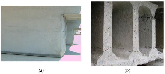
Figure 7.
Cracking caused by splitting in the tendon anchoring zone: (a) TT slab, (b) HC slab [25].
Another typical example that can often be classified as a reinforcement error is the causeless use of beams with dapped ends, especially in cases where they are not justified by the desire to limit the structural height of the story. Using this solution, it is very difficult to avoid cracks (Figure 8), even in the case of correctly designed reinforcement [26,27]. Prestressed tendons compressing the dap wall reduce resistance to cracking because the tensile stress concentrated in the reentrant corner adds up to the previously mentioned splitting and spalling effects. This issue is widely described in the literature [28,29], and yet there are still projects in which the reinforcement of the cut end was underestimated and the horizontal or vertical hanger and shear rebars were insufficiently anchored. Corner cracks typically exceed width limits, so repairing such areas typically involves resin injection and external composite or steel overwrap.
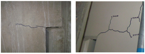
Figure 8.
Cracking of beams in the zone of the dapped end.
3. Defects and Errors Occurring during Manufacturing
Manufacturing errors can be divided into those occurring in precast concrete plants and during the assembly of the segmental unit. Errors occurring in precast concrete factories include material defects and inconsistencies with the design documentation in the arrangement of reinforcement. Thanks to the quality control used by manufacturers, these defects are rare, and if they occur, they are usually disclosed at the factory, where they can be removed. Of course, this does not mean that defective elements never reach construction sites.
3.1. Shape Defects
Filigree shape of the segmental roof girders used in the 1970s would be considered advanced even today. This complexity resulted in the lack of geometric repeatability of the modules, which forced corrections of the geometry during prestressing, sometimes resulting in significant imperfections. This was due to the need to linearly align the cable ducts at the expense of the external geometry of the elements. The most common errors concerned the width of the segmental joints, with a nominal dimension of 25 mm; in practice, joints with a width from 2 to over 50 mm can be found. Examples of such connections are shown in Figure 9 and Figure 10 depicting cable corrosion caused by careless filling of the joints [30]. Refilling the joint will no longer restore the full load-bearing capacity of the damaged tendon.
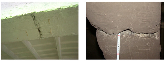
Figure 9.
Examples of faulty segment joints in the lower chords.
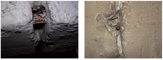
Figure 10.
Visible corrosion of the prestressing cables in the untight joints.
A common geometric defect was also improper assembly of prefabricated posts (Figure 11).

Figure 11.
Incorrect assembly of prefabricated posts.
Another example of a manufacturing defect typical for a frame girder is an incorrect fit of its geometry with the rest of the structure. It may result from insufficient dimensional tolerances of the prestressed elements themselves, but more often it is the result of careless rectification of the supporting elements during assembly. Something particularly dangerous was too shallow girder support (Figure 12), which resulted in local crushing of the concrete due to the edge stress concentration caused by support rotation.
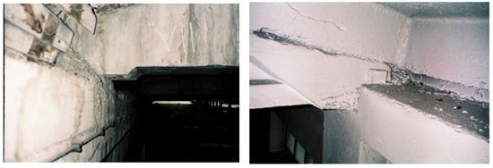
Figure 12.
Examples of too-shallow girder support.
The formerly common use of sheet metal packages or very thick grout to level the support is also controversial. Such a heavily built-up steel support creates drainless space where corrosion of invisible and inaccessible anchorages usually occurs (Figure 13). Inspection of such anchors often requires cutting out part of the casing.
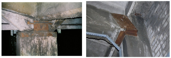
Figure 13.
Examples of drainless spaces around anchor zones.
Nowadays, there are cases where the dowel arrangement does not match the dowel holes arrangement and the elements are “forced” to be joined. Concrete bursting then occurs along the dowel ducts or within the support zones (corbels and column heads). Cases of “forced assembly” can be easily identified by observing gaps in the dowel system, their bend, or clearance inside the dowel holes. In cases of the largest geometric inconsistencies, dowels may be cut out and supplemented, which does not always guarantee the correct load-bearing capacity of the joints repaired in this way.
3.2. Material Defects
Material defects are rare, although they happened to manufacturers, especially during the early years of the development of pre-tensioned structures in Poland. Due to the insufficient quality of cement, contractors had problems with achieving concrete strength of 40 MPa. Elements with significantly lower concrete strength (below 30 MPa) were usually failed during installation. However, girders with visible defects in the concrete structure that affect their tightness have survived to this day (Figure 14).

Figure 14.
Concrete structure defects.
Interestingly, despite quality control, material defects still occur today. At the end of the 1990s and the beginning of this century, surface cracks of railway sleepers caused by the alkali-aggregate reaction [31] and delayed ettringite [32,33] formation were reported in many countries. Recently, the authors of this manuscript came across a case of a girder made of two types of concrete, grossly different in class. The volume of concrete was probably incorrectly estimated during its production and the shortage was filled with concrete made outside quality control. The defect was discovered accidentally, during mechanical roughening of the too smooth upper surface of the girder. It was necessary to remove the weak concrete using hydromonitoring and replacing it with new concrete with appropriate parameters.
3.3. Missing Reinforcement
Errors involving the use of inappropriate prestressing reinforcement are rare, although the authors encountered cases of empty cable ducts, with cables exposed to corrosion. Such unbonding also causes a redistribution of forces [34,35]. The repair involves removing rust and filling in grout gaps.
Defects related to incorrect arrangement of reinforcement mainly concern mild reinforcement. The authors encountered such a case once when checking the transverse reinforcement in the support zone of TT slabs. This was a case in which the correct number of stirrups was used, but there were significant deviations from the designed spacing. The probability of incorrect arrangement of prestressing reinforcement is much lower because this reinforcement can usually be inspected at the front side of the elements. In mounted elements, when this zone is inaccessible, devices such as a mirror or an endoscope can be used.
3.4. Damage Occurring during Prestressing
Damage occurring during prestressing results mainly from the previously discussed incorrect reinforcement design of the anchorage zones. However, incorrect workmanship may contribute to the occurrence of these defects by applying excessive tension on the tendons or releasing them too rapidly [36,37]. Due to the difficulty of determining the extent of tendon slip, units damaged in this way are unsuitable for use and do not reach the construction site. The element may be approved for use only if the damage covers part of the tendons in the support zone; i.e., in the zone of the lowest bending moment.
4. Defects and Errors Occurring during Construction
Prefabrication of prestressed elements is almost always carried out by experienced manufacturers who implement in-house quality control procedures. Lack of experience is much more common among teams carrying out in-place assembly work, which is why most errors occur at this stage. Assembly errors may include the transport of elements, incorrect assembly, and the influence of weather conditions.
4.1. Transport Damages
Although the only load during transport and lifting is the element’s weight, the unusual conditions of temporary support differ from the planned structural scheme, which when combined with the prestressing force, may lead to damage [38]. Manufacturers usually very precisely define the zones and the directions in which elements can be temporarily supported. TT beams and slabs are armed with handles for lifting devices, and the HC slabs should be lifted using appropriate clamps with spreader bars and side grooves, sometimes through a special set of hooks inserted into the voids. Prestressing can raise phenomena such as lateral instability [39,40]. Negligence such as storing beams sideways or lifting them incorrectly may lead to deformation or cracks. Such elements are often no longer suitable for installation. Improper handling of the hollow-core slabs during lifting, due to the lack of transverse reinforcement, may even result in their breakage. Examples of the discussed failures are shown in Figure 15.

Figure 15.
Precast elements damaged during assembly: (a) HC slab lifted incorrectly, (b) girder overturned while maneuvering on the construction site.
4.2. Defects of Cast in Place and Topping Concrete
Some beams require connection with the ceiling or roof structure by placing a concrete topping. It has a significant impact on the load-bearing capacity and stiffness [41], and making it from too weak concrete reduces these parameters. Figure 16a shows an example of an old industrial hall in which all girders were made of concrete topping with a pumice structure and practically zero strength. Figure 16b shows an example of a modern construction of a prestressed concrete beam in the ceiling, in which during the installation of the concrete topping reinforcement, the contractor in seeking to make their work easier, cut some of the stirrups coming out of the prestressed concrete element. Supplementing the tying reinforcement usually requires chemical anchoring of the rebars, which is therefore expensive and time-consuming.
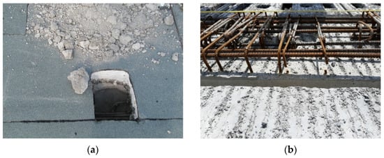
Figure 16.
Examples of concrete topping defects: (a) roof girder—very weak concrete with defective structure, (b) ceiling beam—cut stirrups.
4.3. Inadequate Protection in Winter Conditions
The advantage of prefabrication is the ability to build in any weather conditions, including negative temperatures. In low-quality concrete, water can accumulate in the porous structure of the concrete and freeze [42]. Freezing water rapidly expanding as a result of phase transformation and at the same time restrained by the surrounding concrete causes micro- and macro-cracking of its structure. This affects the strengths, elastic modulus, and reinforcement bond [43]. Similar damage may result from differences in the thermal expansion of ice and concrete [44]. The use of high-quality concrete in prefabrication usually avoids these problems. However, contractors forget that installation in winter conditions involves several specific dangers, especially in northern countries or mountain regions with longer periods of negative temperatures [45]. Prestressed concrete elements often have openings or large voids where water can accumulate. The ducts for embedding the dowels in the supporting elements are usually secured with plugs, but if they are damaged or lost, water may penetrate them, and then they may freeze and burst the unit (Figure 17a). The neoprene pad acts in this case as a gasket. Similar damage may also occur in the case of holes made “through”, e.g., in the ends of girders and railway sleepers [46] because the elastomeric bearings on which the elements are supported act as seals that prevent water from flowing out of the dowel holes. Therefore, in winter, the holes may be partially filled with water and then frozen. Ice first in dendritic form, then as solid annulus (Figure 18), grows radially from the wall [47] leading to the structure bursting (Figure 17b). Yet another example may be the freezing of water in the voids of HC plates. The authors encountered a case in which the contractor, guided by intuition, made drainage holes in the slab voids, but unfortunately only in the span zones, while the negative camber caused water to accumulate in the support zones, where the slab bursts locally.
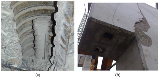
Figure 17.
Damage to beams within the pole holes as a result of water freezing: (a) in the column [48], (b) in the girder.
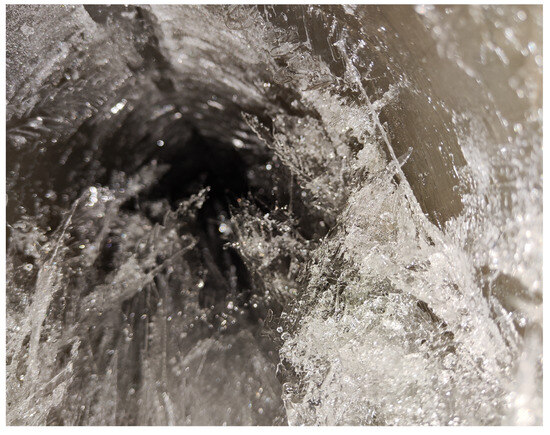
Figure 18.
Ice formed inside the void of the HC slab (dendritic formations visible).
Another case of frost-induced damage the authors dealt with was an uncommon V-type prestressed beam with closed ends. The beam was installed in late autumn and covered with a roof shortly thereafter. The shape of the beam created a trough in which rainwater collected and then froze. This led to the formation of severe cracks, shown in Figure 19. The cracks did not damage the prestressing reinforcement, so repair by injection was ordered in this case.
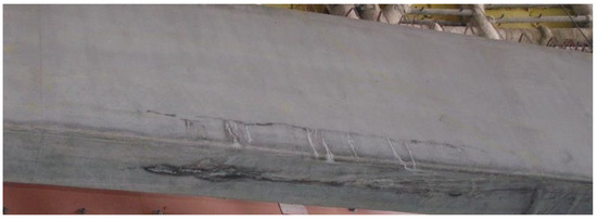
Figure 19.
Damage to the V-beam caused by freezing of water accumulated in the trough.
5. Defects Occurring during the Use of Structural Elements
The advantage of concrete structures is their high durability achieved with relatively low maintenance requirements. This does not mean that these structures are completely resistant to environmental impacts and do not require protection and periodic renovation. This applies especially to thin-walled and therefore more sensitive prestressed structures.
5.1. Improper Use
One of the typical disadvantages of use is the loading of prestressed units in places and to an extent for which they were not intended. Industrial hall users can hang various devices from the girders, often in random places. Of course, girder designs provide for mounting the runway beams of winches and other concentrated loads. It should be carried out in the zones designated for this purpose and without disturbing the concrete structure, especially in the area of prestressing tendons. If the girder is not equipped with appropriate mounting points, it is best to use clamps that allow for the loads to be transferred to the upper chords. In a curious case known to the authors, a fragment of a tension cable was forged and a hoist hook was welded to it. In another case, a trailer with grain was pulled into the hall using a hoist attached to the lower chord of the girder. Interestingly, it withstood such use, which proves its significant reserves of load-bearing capacity.
A common example of unusual and dangerous loads on girders is contamination accumulated over many years of use. Figure 20 shows the dust load on the lattice girders, estimated at approximately 5 kN/m.
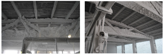
Figure 20.
Dust load on the lower chords of the girders.
Another frequent usage error is the mounting of equipment using mechanical and chemical anchors in the zones of the prestressing tendons. Drilling holes near the strands always involves the risk of cutting one or more wires within the strand. Such procedures are particularly dangerous in post-tensioned concrete prestressed with tendons without bond. In prestressed concrete, such damage is local, but in the zones of maximum bending moments, it may limit the load capacity or cause a slight increase in deflections. Moreover, such damage may constitute a notch, which may be a source of crack development, which can affect the durability of the structure. The mentioned holes are most often drilled for mounting installations, cables, and lamps (Figure 21).
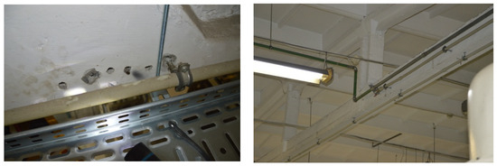
Figure 21.
Examples of damage caused by faulty installation of equipment.
Anchors should not be placed too close to the edge. Not only does it pose a risk of damaging the elements (Figure 22), but it also does not meet the basic rules for placing anchors.
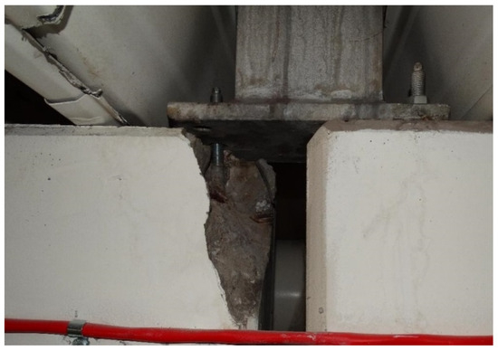
Figure 22.
Incorrect anchoring of the air conditioning unit to the roof girders.
5.2. Poor Condition of Roofing and Insulation
Most of the prestressed elements discussed in this manuscript operate in favorable conditions, inside closed industrial facilities. Environmental hazards in this situation most often result from leaks in the roof covering, which results in flooding of structural elements, most strongly in the lines between the bays (Figure 23) or along the edge of the roof (Figure 24). Leaks may be the result of wear and tear of the layers sealing the roof covering, as well as a result of work on the roof surface (e.g., snow removal).

Figure 23.
Effects of long-term moisture of a post-tensioned concrete girder.
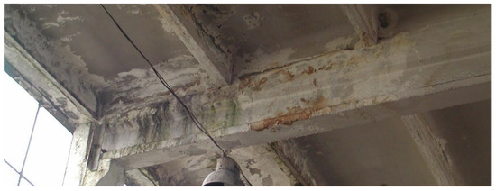
Figure 24.
Effects of long-term moisture of a prestressed concrete girder.
In post-tensioned concrete, the joints of segments and cable anchoring zones are most susceptible to moisture; improper filling of cable ducts, where water may accumulate, is also a threat. Tendon protection in pre-tensioned concrete structures is better because the prestressing reinforcement is directly covered with structural concrete with good parameters, including high tightness. The higher durability of pre-tensioned concrete structures does not mean, however, that they do not require periodic renovation and, in justified cases, the use of protective coatings.
The possible effects of use in unfavorable conditions are shown in Figure 25. Pre-tensioned concrete beams supported the chimney flue of an old-fashioned power plant. Sulfur icicles were visible. The prestressing tendons at the ends of the beams were exposed. Concrete tests showed a complete loss of steel passivation (pH < 10) and the permissible content of sulphate ions (up to 15%) was exceeded by several times.
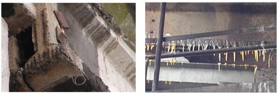
Figure 25.
Prestressed concrete beams corroded by long-term exposure to exhaust gases containing sulfur compounds.
Another interesting example of use in extremely unfavorable conditions is shown in Figure 26. The girder used above the furnace was heavily corroded and contaminated. In such cases, it is necessary to use a thermal covering that protects not only the concrete, but also primarily the prestressing tendons exposed to accelerated relaxation.
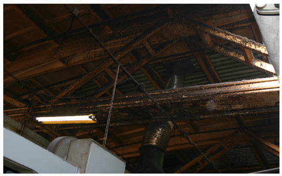
Figure 26.
Corrosion of a roof girder used above the furnace.
5.3. Renovation Errors
A significant number of renovation errors concern roofing. These include changes in the arrangement of roof slabs, making additional openings or eliminating existing ones (Figure 27), changes in the arrangement of roofing layers (sometimes leading to significant loads), and the adding of layers not considered in the design, as well as temporary overloads, e.g., during renovation works. Avoiding such errors requires experienced supervision, reflecting awareness of the specificity of prestressed structures.
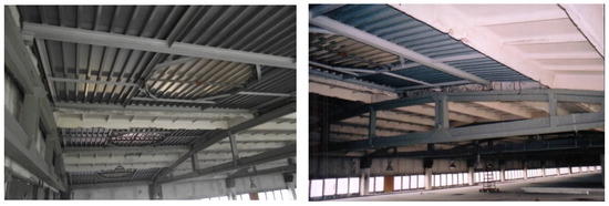
Figure 27.
Examples of changes to roofing structures.
6. Conclusions
This manuscript presents and classifies the most typical cases of defects and damage to prestressed elements used mainly in industrial construction. This type of structure has been used in Poland for over 70 years. Despite many economic problems during the introduction period, most of the prestressed elements were made to a good technical standard and, if used properly, do not cause any major operational problems even now. An intensive return to pre-tensioned concrete structures took place at the beginning of this century. New manufacturers and technologies appeared, which required learning and improvement. The defects and errors discussed in this manuscript come mainly from this period, but it should be noted that they are becoming less and less common nowadays.
The proposed classification includes damage resulting from design, production, assembly, and use errors. The causes of most of these failures are obvious and easy to identify, although there are also cases where determining the causes required a thorough investigation including material tests, nondestructive technique tests, strength analyses, and sometimes climatic and historical analyses.
Table 1, Table 2, Table 3 and Table 4 summarize the most common types of errors discussed in this manuscript. Of course, they do not cover the spectrum of all errors that can be found in prestressed structures. These are only cases encountered by the authors in their professional practice in Poland. The classification presented in Table 1, Table 2, Table 3 and Table 4 is also supplemented with the frequency with which the mentioned defects and errors were encountered and the recommended repair and mitigation methods.

Table 1.
List of common defects and errors occurring during design.

Table 2.
List of common defects and errors occurring during manufacturing.

Table 3.
List of common defects and errors occurring during construction.

Table 4.
List of common defects and errors occurring during use.
The analysis of the tables and the examples discussed clearly show that most errors occur at the technology implementation stage. In Poland, it was during the 1960s and then again during the 1990s, which resulted from the bankruptcy of the economy and the need to re-implement the somewhat forgotten technology of compressing concrete. Despite the growing product market and the growing number of manufacturers, the number of potential defects and errors is decreasing. The experience of manufacturers and the growing quality requirements mean that the quality of prefabricated elements delivered to construction sites is increasingly higher. The most common problems today concern assembly, especially when carried out in excessive haste, without the required technological breaks or taking into account weather conditions.
The authors believe that the presented examples can be helpful in identifying many similar cases, which is why they illustrated them with rich photographic documentation originating entirely from their own archives.
Author Contributions
Conceptualization, J.H. and R.K.; methodology, J.H. and R.K.; investigation, J.H. and R.K.; resources, J.H. and R.K.; data curation, J.H. and R.K.; writing—original draft preparation, R.K. and J.H.; writing—review and editing, R.K.; visualization, J.H. and R.K.; supervision, J.H. All authors have read and agreed to the published version of the manuscript.
Funding
This research was funded by the Silesian University of Technology, grant BK-230/RB6/2024.
Data Availability Statement
The raw data supporting the conclusion of this article will be made available by the authors on request.
Conflicts of Interest
The authors declare no conflicts of interest.
References
- Sanabra-Loewe, M.; Capellà-Llovera, J. The four ages of early prestressed concrete structures. PCI J. 2014, 59, 93–121. [Google Scholar] [CrossRef][Green Version]
- Marrey, B.; Grote, J. The story of prestressed concrete from 1930 to 1945: A step towards the European Union. In Proceedings of the First International Congress on Construction History, Madrid, Spain, 20–24 January 2003. [Google Scholar]
- Burgoyne, C. Early Applications of Prestressed Concrete in the United Kingdom. In SP-231: Ned H Burns Symposium on Historic Innovations in Prestressed Concrete; Russel, B.W., Gross, S.P., Eds.; ACI: Kansas City, MO, USA, 2005; pp. 15–32. [Google Scholar]
- Nasser, G.D.; Tadros, M.; Sevenker, A.; Nasser, D. The legacy and future of an American icon: The precast, prestressed concrete double tee. PCI J. 2015, 60, 49–68. [Google Scholar] [CrossRef]
- Van Acker, A.; Maas, S. Historical Development of Hollow Core Slabs. CPi 2021, 2, 112–123. [Google Scholar]
- Galvao, N.; Matos, J.; Hajdin, R.; Ferreira, L.; Stewart, M.G. Impact of construction errors on the structural safety of a post-tensioned reinforced concrete bridge. Eng. Struct. 2022, 267, 114650. [Google Scholar] [CrossRef]
- Elliot, K.S.; Hamid, Z.A. Modernisation, Mechanisation and Industrialisation of Concrete Structures; JohnWiley & Sons Ltd.: Chichester, UK, 2017; p. 481. [Google Scholar]
- Matos, J.C.; Nicoletti, V.; Kralovanec, J.; Sousa, H.S.; Gara, F.; Moravcik, M.; Morais, M.J. Comparison of Condition Rating Systems for Bridges in Three European Countries. Appl. Sci. 2023, 13, 12343. [Google Scholar] [CrossRef]
- Kapusta, L.; Szojda, L. The role of expansion joints for traditional buildings affected by the curvature of the mining area. Eng. Fail. Anal. 2021, 128, 105598. [Google Scholar] [CrossRef]
- Engström, B.; Alexander, S.; Cholewicki, A.; De Chefdebien, A.; Della Bella, B.; Elliott, K.S.; Ordoñez, D.F.; Menegotto, M.; Newby, M.; Rise, G.; et al. Structural Connections for Precast Concrete Buildings; fib bulletin 43; International Federation for Structural Concrete: Lausanne, Switzerland, 2008; p. 369. [Google Scholar]
- Ahmed, A.; Fayyadh, M.M.; Naganathan, S.; Nasharuddin, K. Reinforced concrete beams with web openings: A state of the art review. Mater. Des. 2012, 40, 90–102. [Google Scholar] [CrossRef]
- Amiri, S.; Masoudnia, R.; Pabarja, A.A. The Study of the Effects of Web Openings on the Concrete Beams. Aust. J. Basic Appl. Sci. 2011, 5, 547–556. [Google Scholar]
- Elkafrawy, M.; Khalil, A.; AlHamaydeh, M.; Hawileh, R.; Abuzaid, W. Enhancing the Shear Capacity of RC Beams with Web Openings in Shear Zones Using Pre-Stressed Fe-SMA Bars: Numerical Study. Buildings 2023, 13, 1505. [Google Scholar] [CrossRef]
- Mansur, M.A. Design of reinforced concrete beams with web openings. In Proceedings of the 6th Asia–Pacific Structural Engineering and Construction Conference (APSEC 2006), Kuala Lumpur, Malaysia, 5–6 September 2006. [Google Scholar]
- Mercan, B.; Schultz, A.E.; Stolarski, H.K.; Magana, R.A. Long term lateral deflection of precast, prestressed concrete spandrel beams. PCI J. 2013, 58, 93–115. [Google Scholar] [CrossRef]
- Raths, C.H. Spandrel beam behavior and design. PCI J. 1984, 29, 63–131. [Google Scholar] [CrossRef]
- Bairan, J.M.; Cladera, A. Collapse of a precast concrete beam for a light roof. Importance of elastomeric bearing pads in the element’s stability. Eng. Fail. Anal. 2014, 39, 188–199. [Google Scholar] [CrossRef]
- Elliot, K.S.; Davies, G.; Gorgun, H. The Stability of Precast Skeletal Structures. PCI J. 1998, 43, 42–60. [Google Scholar] [CrossRef]
- He, Z.-Q.; Chen, J.; Liu, Z.; Ma, Z.J. Analytical approach for bursting cracking analysis of post-tensioned anchorage zone. Structures 2023, 52, 401–409. [Google Scholar] [CrossRef]
- Gálvez, J.C.; Benítez, J.M.; Tork, B.; Casati, M.J.; Cendón, D.A. Splitting failure of precast prestressed concrete during the release of the prestressing force. Eng. Fail. Anal. 2009, 16, 2618–2634. [Google Scholar] [CrossRef]
- Yu, H. Causes and Prevention of Splitting/Bursting Failure of Concrete Crossties: A Computational Study. In Proceedings of the American Railway Engineering and Maintenance-of-Way Association (AREMA) Annual Conference, Indianapolis, IN, USA, 17–20 September 2017. [Google Scholar]
- Babarinde, O.; Sun, C.S.; Farzana, N.; Kuruppuarachchi, D. Analytical study of splitting resistance of precast prestressed ultra-high performance concrete girder end zones. Eng. Struct. 2023, 289, 116314. [Google Scholar] [CrossRef]
- Ross, B.E.; Willis, M.D.; Hamilton, H.R.; Consolazio, G.R. Comparison of details for controlling end-region cracks in precast, pretensioned concrete I-girders. PCI J. 2014, 59, 96–108. [Google Scholar] [CrossRef]
- Ronanki, V.S.; Burkhalter, D.I.; Aaleti, S.; Song, W.; Richardson, J.A. Experimental and analytical investigation of end zone cracking in BT-78 girders. Eng. Struct. 2017, 151, 503–517. [Google Scholar] [CrossRef]
- Derkowski, W.; Dyba, M. Behaviour of end zone of pre-tensioned concrete elements. Procedia Eng. 2017, 193, 19–26. [Google Scholar] [CrossRef]
- Aswin, M.; Al-Fakih, A.; Syed, Z.I.; Liew, M.S. Influence of Different Dapped-End Reinforcement Configurations on Structural Behavior of RC Dapped-End Beam. Buildings 2023, 13, 116. [Google Scholar] [CrossRef]
- Mohammed, B.S.; Aswin, M.; Liew, M.S.; Zawawi, N.A. Structural Performance of RC and R-ECC Dapped-End Beams Based on the Role of Hanger or Diagonal Reinforcements Combined by ECC. Int. J. Concr. Struct. Mater. 2019, 13, 44. [Google Scholar] [CrossRef]
- Klein, G.; Botros, A.; Andrews, B.; Holloway, K. Dapped ends of prestressed concrete thin-stemmed members: Part 1, experimental testing and behavior. PCI J. 2017, 62, 61–82. [Google Scholar] [CrossRef]
- Masenas, V.; Meskenas, A.; Valivonis, J. Analysis of the Bearing Capacity of Reinforced Concrete Dapped-End Beams. Appl. Sci. 2023, 13, 5228. [Google Scholar] [CrossRef]
- Koseki, K.; Breen, J.E. Exploratory Study of Shear Strength of Joints for Precast Segmental Bridges; Research Report no. 248-1; Evaluation of AASHTO Shear and Torsion provisions for reinforced and Prestressed Concrete; State Department of Highways and Public Transportation: Austin, TX, USA, 1983; p. 111. [Google Scholar]
- de Souza Lima, E.H.; Pereira Carneiro, A.M. A review of failures of railway monoblock prestressed concrete sleepers. Eng. Fail. Anal. 2022, 137, 106389. [Google Scholar] [CrossRef]
- Hime, W.G. Delayed Ettringite Formation A Concern for Precast Concrete? PCI J. 1996, 41, 26–30. [Google Scholar] [CrossRef]
- Sahu, S.; Thaulow, N. Delayed ettringite formation in Swedish concrete railroad ties. Cem. Concr. Res. 2004, 34, 1675–1681. [Google Scholar] [CrossRef]
- Walczak, R.; Derkowski, W. Shear capacity tests of PC crane beams in uncertain prestressing tendons anchorage conditions. In Proceedings of the 6th fib International Congress 2022, Oslo, Norway, 12–16 June 2022. [Google Scholar]
- Ajdukiewicz, A.; Kliszczewicz, A.; Hulimka, J. Special aspects of diagnostics of post-tensioned concrete roof girders. Inżynieria Bud. 1995, 3, 163–167. [Google Scholar]
- Mirza, J.F.; Tawfik, M.E. End Cracking in Prestressed Members during Detensioning. PCI J. 1978, 23, 66–78. [Google Scholar] [CrossRef]
- Kannel, J.J.; French, C.E.; Stolarski, H.K. Release Methodology of Prestressing Strands; Final Report; Minnesota Department of Transportaion: St. Paul, MN, USA, 1998; p. 280. [Google Scholar]
- Khayam, S.U.; Won, J.; Shin, J.; Park, I.; Park, J.-W. Monitoring Precast Structures During Transportation Using a Portable Sensing System. Autom. Constr. 2023, 145, 104639. [Google Scholar] [CrossRef]
- de la Fuente, A.; Bairána, J.M.; Cavalaro, S.H.P. Case study of failure of long prestressed precast concrete girder during lifting. Eng. Fail. Anal. 2019, 100, 512–519. [Google Scholar] [CrossRef]
- Stratford, T.J.; Burgoyne, C.J. Lateral stability of long precast concrete beams. Proc. Inst. Civ. Eng. Struct. Build. 1999, 124, 169–180. [Google Scholar] [CrossRef]
- Nabil, A.; Meleka, N.; Heiza, K. Effects of Different Types of Concrete Toppings on The Behavior of PPHC Slabs. Eng. Res. J. 2017, 40, 333–339. [Google Scholar]
- Sun, Z. Mechanism of Frost Damage to Concrete. Ph.D. Thesis, Princeton University, Princeton, NJ, USA, March 2010. [Google Scholar]
- Hanjari, K.Z.; Utgennant, P.; Lundgren, K. Experimental study of the material and bond properties of frost damaged concrete. Cem. Concr. Res. 2011, 41, 244–254. [Google Scholar] [CrossRef]
- Valenza, J.J.; Scherer, G.W. Mechanism of salt scaling. J. Am. Ceram. Soc. 2006, 89, 1161–1179. [Google Scholar] [CrossRef]
- Koci, J.; Madera, J.; Pommer, V.; Cerny, R. Analysis of the Frost-Induced Damage of Building Enclosures on the Territory of the Czech Republic. Adv. Mater. Sci. Eng. 2018, 2018, 3421801. [Google Scholar] [CrossRef]
- Zi, G.; Moon, D.Y.; Lee, S.-J.; Jang, S.J.; Yang, S.C.; Kim, S.-S. Investigation of a concrete railway sleeper failed by ice expansion. Eng. Fail. Anal. 2012, 26, 151–163. [Google Scholar] [CrossRef]
- Akyurt, M.; Zaki, G.; Habeebullah, B. Freezing phenomena in ice–water systems. Energy Convers. Manag. 2002, 43, 1773–1789. [Google Scholar] [CrossRef]
- Wojciechowski, S.; Deskur, B.; Szulc, W. Potential risk of failure on prefabricated construction building with selected examples. In Proceedings of the XXVII Conference Structural Failures, Szczecin, Poland, 22–26 May 2017; pp. 111–124. [Google Scholar]
Disclaimer/Publisher’s Note: The statements, opinions and data contained in all publications are solely those of the individual author(s) and contributor(s) and not of MDPI and/or the editor(s). MDPI and/or the editor(s) disclaim responsibility for any injury to people or property resulting from any ideas, methods, instructions or products referred to in the content. |
© 2024 by the authors. Licensee MDPI, Basel, Switzerland. This article is an open access article distributed under the terms and conditions of the Creative Commons Attribution (CC BY) license (https://creativecommons.org/licenses/by/4.0/).