Abstract
Cold-formed steel (CFS) sections constructed with high-strength steel have gained prominence in construction owing to their advantages, including a high strength-to-weight ratio, shape flexibility, availability in long spans, portability, cost-effectiveness, and design versatility. However, the thin thickness of CFS members makes them susceptible to various forms of buckling. This study focuses on addressing and mitigating different types of buckling in columns and beams by manipulating the lip length (d) and the ratio of inside radius to thickness (Ri/t) in CFS C-sections. To achieve this objective, a comprehensive analysis involving 176 models was conducted through the Finite Element Method (FEM). The findings reveal that an increase in lip length leads to a corresponding increase in critical elastic buckling load and moment (, , , , , and ). It is recommended to utilize a lip length greater than or equal to 15 mm for both columns and beams to mitigate various buckling types effectively. Conversely, an increase in the ratio of inside radius to thickness (Ri/t) results in an increase in critical elastic local buckling load () and moment (). Thus, lip length (d) significantly influences column and beam buckling, whereas Ri/t exhibits a relatively impactful effect. Subsequently, the experimental test results were used to verify finite element models. These insights contribute significant knowledge for optimizing the design and performance of CFS C-sections in structural applications.
1. Introduction
Cold-formed steel (CFS) structural elements have asserted their dominance in the light-gauge building sector, offering numerous advantages over their hot-rolled counterparts. These advantages encompass a superior strength-to-weight ratio, portability, adaptability to various jointing techniques, cost-effectiveness in production, stringent quality control, consistent dimensions, and enhanced profile design flexibility. The thinness of CFS sections exposes them to various buckling phenomena. This study specifically looks at what happens when the lip length (d) and the ratio of the inner radius to thickness (Ri/t) are changed in CFS C-sections. It looks at how these changes affect different types of buckling in columns and beams, such as local, distortional, and flexural buckling. The incorporation of lips, small additional components, is a strategic measure to augment the effectiveness of a section under compressive pressures [1,2]. While lip length significantly influences cross-sectional stability, it remains a challenging parameter to manage during the roll-forming process [3].
In the realm of CFS sections, the inside radius refers to the curvature or rounded corner at the meeting point of two surfaces or components within the steel section. Specifically associated with the flange–web connection of a cold-formed steel profile, this radius holds critical importance as it shapes the geometric form of the section and profoundly influences structural behavior, particularly in resisting buckling loads and moments.
Commonly employed as flexural members in structural frames, traditional hat, Z, and C CFS members exhibit inherent characteristics of cold-formed steel (CFS), leading to local, distortional, and global buckling challenges, even when subjected to stress levels below yielding strength [4,5]. Prior research endeavors [6,7,8,9] have extensively explored the structural performance of hollow flange sections, addressing web-crippling, shear, and bending phenomena to mitigate buckling instabilities. The advent of the direct strength method (DSM) [10] brought attention to the distinctive profiles of CFS members, prompting detailed analysis using sophisticated finite element (FE) software programs and advanced manufacturing techniques. Modern methodologies, including non-destructive testing, such as the widely used 3MA methods [11,12,13], offer comprehensive evaluations of mechanical characteristics, including tensile and yield strength.
In light of these advancements, this study focuses on the intricate interplay between inside radius, lip length (d), and the behavior of CFS members at local, distortional, and global levels. A comprehensive investigation is imperative to optimize the design and structural performance of CFS elements. This paper aims to unravel the nuanced effects of variations in inside radius and lip length on the behavior, load-carrying capacity, and stability of C-section CFS beams and columns.
2. Impact of Lips
The length of the lips in CFS sections typically refers to the measurement of the downturned or outward-extending portions at the edges of the flanges. These lips contribute to the overall geometry of the CFS member.
Furthermore, significant emphasis should be placed on the web-to-lip width ratio (D/d) [14]. The impact of lip size on stiffness is negligible, whereas it has a substantial influence on the resistance to DB and, consequently, the flexural capacity of Z sections [15]. Conversely, in local and distortion samples, a reduction in lip depth maintained a greater capacity along the hysterical curve, whereas its impact was negligible in global tests [16].
It has been ascertained that reducing the nominal lip size of sections from its current value of 20 mm would result in a decrease in efficiency, whereas increasing the nominal lip size would yield benefits for certain sections [17]. Additionally, sections with the narrowest lip dimension were found to fail under the stiffener buckling phase [18]. Furthermore, for axial and/or positively compressed columns, the contribution of the batten sheets to the columns’ strength decreased significantly as the lip width or batten sheets’ space increased [19]. Moreover, the use of an edge stiffener has been shown to greatly boost the critical moment [20].
2.1. Shapes of Sections According to Symmetry
The curved lips of the components enhance safety when handling on site compared to sharp edges [21]. Stiffeners have been included in the flanges, webs, and lips of the channel and zed sections in recent advancements to enhance their buckling capabilities. These modified sections are often referred to as SupaCee and SupaZed [22]. According to the cited source, the inclusion of a lip stiffener in both C-section and Z-section structures results in a significant enhancement in strength when compared to structures without a lip stiffener [22].
The inclusion of lips in the Z and HAT sections has been shown to improve the load-bearing capacity and decrease the deflection of the structural component [23]. The phenomenon of bending constantly manifested itself in the direction towards the web in the plain channels and at the lips in the lipped channels [24]. In the case of bending along the axis that is horizontal, reducing the slope of the lip results in a reduction in the DB by about 10% (from 75°) to 40% (from 45°) as compared to the reference angle of 90°. In contrast, the influence of the lip angle change on both DB and LB is shown in the case of bending on the vertical axis [25]. The failure mechanism of the doubly symmetric box section with an inside lip is attributed to the overall buckling of the web in regions where the lip is absent. On the other hand, the failure of singly symmetric channel sections with a lip is primarily caused by overall buckling, whereas without a lip, failure occurs due to LB of the flange. Both failure modes are observed to transpire between one third and the mid-height of the specimen [26].
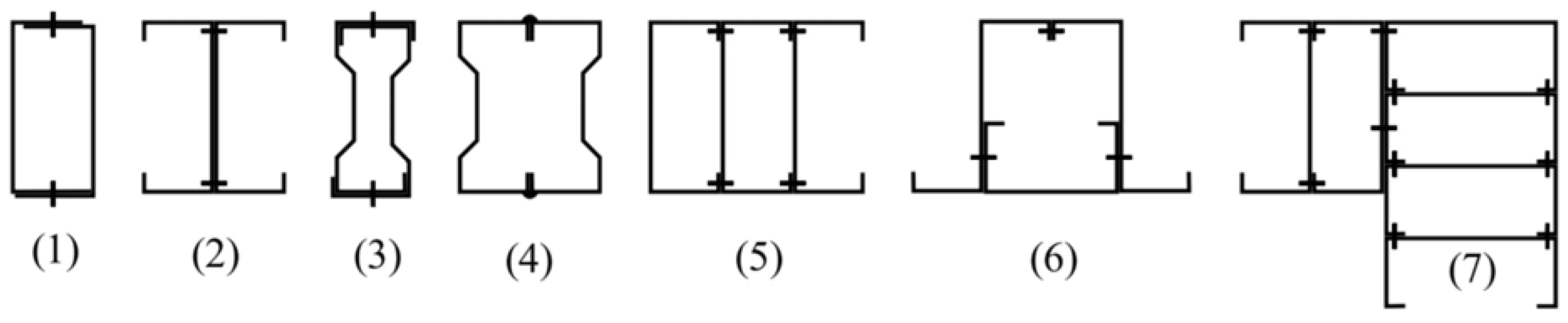
Concerning the geometrical configurations of cold-formed steel (CFS) sections in relation to symmetry: The initial doubly symmetric section is a geometric shape that exhibits symmetry around two perpendicular axes that intersect at its centroid. The second thing to consider is a symmetric section, which refers to a section that exhibits symmetry around a central point, known as the centroid. An equal-flanged Z-section is an example of a member that is symmetrical around a point (the centroid). A third singly symmetric (monosymmetric) section refers to a section that exhibits symmetry only along a single axis passing through its centroid. The fourth non-symmetric section refers to a section that lacks symmetry with respect to both an axis and a point (see Figure 1) [27,28,29,30].
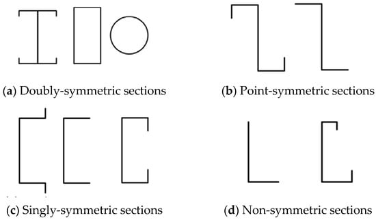
Figure 1.
Examples of section symmetry.
2.2. Single-Steel Member Dimensions
Cold-formed steel (CFS) elements are formed by either cold- or hot-rolled coils or sheets via roll-forming or press-braking blanks that have been sheared from sheets; both forming processes are carried out at room temperature, i.e., without the obvious addition of heat needed for hot forming [29]. On the other hand, individual structural sections consist of closed built-up members, open built-up sections, and single open portions [31].
The curved shape of the sections’ lips enhances safety during on-site handling [22]. In the case of members experiencing compression, it is necessary for the ratio of the web to flange dimensions to be less than 3. According to reference [32], it is necessary for channels in flexure with return lips to have a flange-to-simple lip ratio that exceeds 3.33. In comparison to the optimum lipped channel member and the commercial member, the folded-flange member [33] exhibits a flexural capacity that shows an increase of 57% and 22%, respectively, when considering an equal quantity of material. The impact of strain hardening on the strength variation at the rounded corner zones is generally insignificant (less than one percent) for both plain and lipped channel columns [34].
Cold-formed structural elements fall into two main categories. [31] states that: first, individual structural framing members; these have thicknesses ranging from approximately 0.50 mm to 6.0 mm and depths ranging from 50.0–70.0 mm to 350.0–400.0 mm for bar members; second, panels and decks have thicknesses between 0.40 and 1.50 mm and depths typically between 20.0 and 200.0 mm. In contrast, it is often observed that the depth of frame parts that are cold-formed individually typically varies between 50.80 and 406.0 mm, while the material’s thickness varies between 0.8360 and 2.9970 mm. In certain instances, the profundity of individual members in transportation and building construction may reach 457.0 mm, and their thickness may be 12.70 mm or greater [30]. Moreover, the range of Standard Web Depth for C-shapes (S) spans from 41.30 mm to 356.0 mm. The established range for the lip length of C-shaped standard designs (S) is from 4.80 mm to 25.40 mm. The accepted range for the inside bend radius in standard design is reported to be 2.1410 mm to 4.7320 mm [35].
2.3. Major Modes of Buckling
The inclusion of the lip [18] serves to mitigate or avoid the occurrence of LB in the flange, hence preventing abrupt failure and collapse. It is advisable to refrain from suspending loads from the lips [22]. The number of half-waves buckling lips in a member of typical section and length may range from two to four [36], contingent upon the thickness of the section. Additionally, lipped channel columns that possess frequently used shapes [37] may encounter significant local–distortional–global (LDG) interaction. However, it should be noted that CFS-lipped channel studs [38] experienced failure due to distortional buckling. On the other hand, when used with longer built-up parts and bigger built-up elements, the adjusted slenderness ratio is a safer choice. Furthermore, less local bowing is seen in the members with the lip under a fixed support [39]. So, making a lip by turning the free edge of an unstiffened lip in or out can make the local bending resistance of a member a lot better [18]. Though LB capacity changes when the lips are unfolded, the difference between the LB capacity of unfolded lips and folded lips is 1.05 [40].
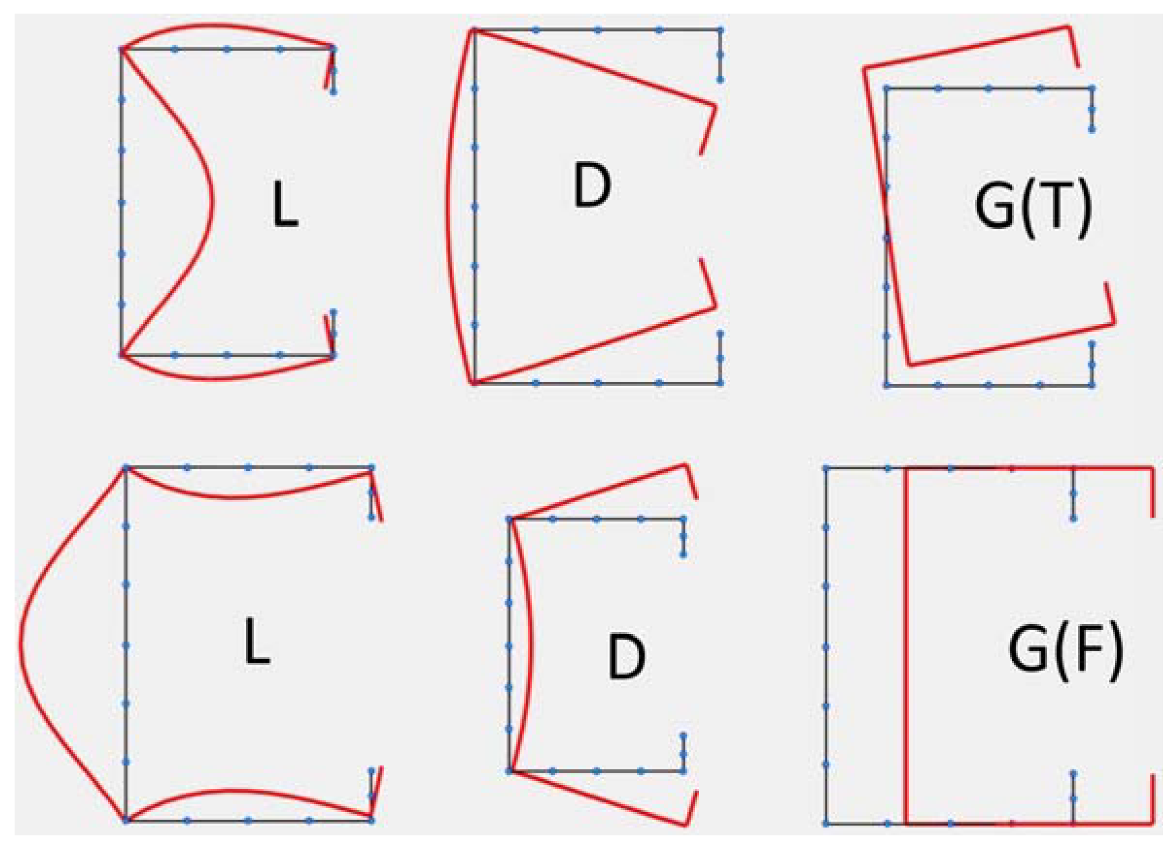
There are three possible modes of elastic buckling for CFS elements (see Figure 2): global (GB), distortional (DB), and local (LB). The modes of global buckling are the phenomenon of lateral–torsional (LTB) buckling in beams and buckling of columns that may be flexural (FB), torsional (TB), or mixed flexural and torsional (FTB) [28,30,41,42].
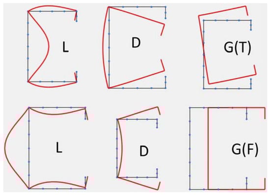
Figure 2.
Buckling modes for a lipped channel in compression. Single modes: local (L); distortional (D); Global (torsional) G(T); Global (flexural) G(F).
Local buckling, defined as a compression element’s limit state of buckling in which the angles and line junctions between the elements stay constant [28,29,30,31,41,43], is a critical consideration. When the screw spacing of columns consisting of CFS I-sections exceeds the half-wavelength of the local buckling of the corresponding C-shaped profile components, suppression of local buckling becomes impossible. Moreover, the test demonstrated that LD interaction and LDG interaction were observed in short, built-up CFS columns and intermediate-length columns, respectively [44]. Additionally, it was discovered that shear and distortional buckling are frequent failure modes for low-gauge steel sections [45].
Distortional buckling, identified as a form of buckling that, in contrast to local buckling, entails a change in the configuration of the cross-sectional shape [28,29,30,31,41,43], plays a crucial role in the structural behavior. In a numerical investigation assessing the axial strength of built-up columns composed of double-lipped sections joined with double back-to-back track elements’ flanges, local buckling was found to govern short-column failure modes. Conversely, the interactive local–overall distortional buckling emerged as the failure mechanism for columns of intermediate height. Furthermore, for long columns, total distortional buckling became the predominant mode of failure [46]. In the case of specimens with a low slenderness ratio and a low width-to-thickness ratio [47], distortional buckling occurs.
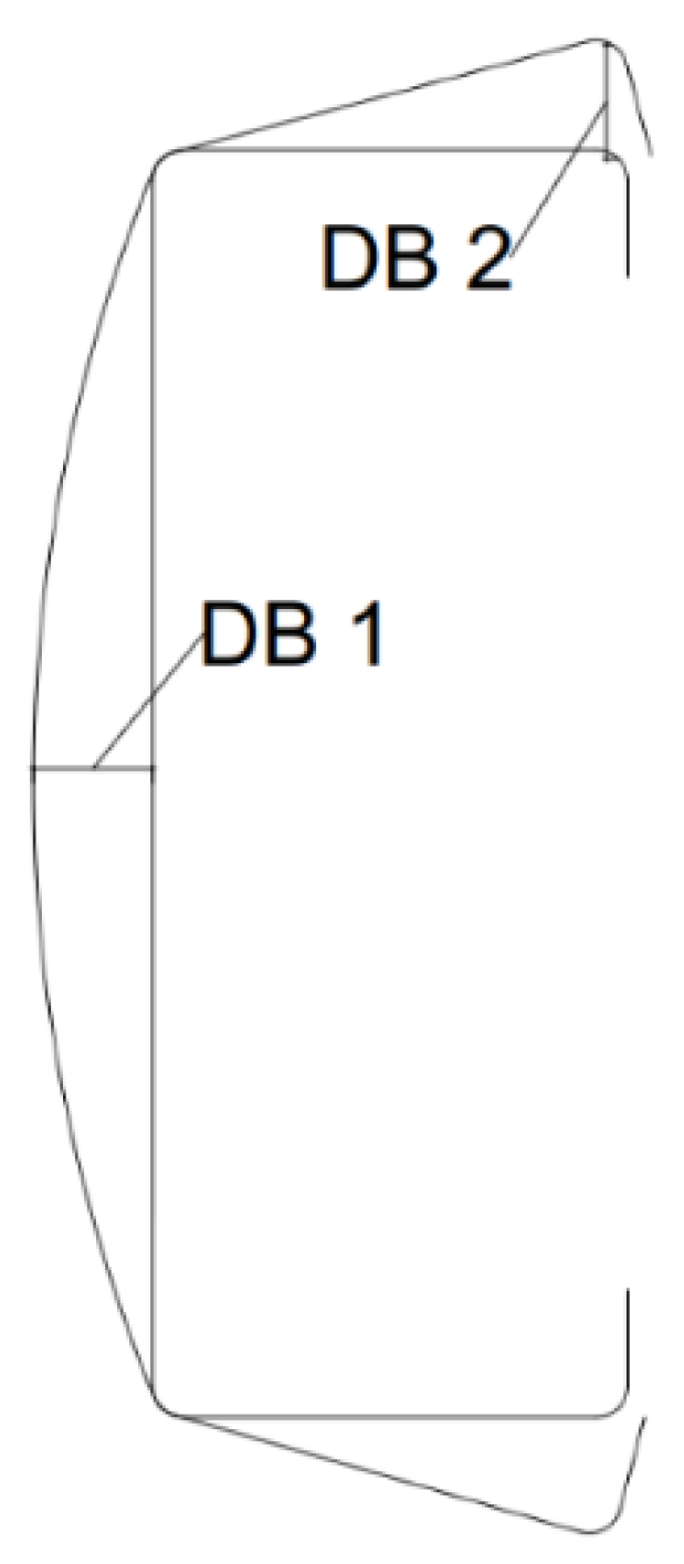
Additionally, adhering to the rule of thumb [48], the proportion between the width and thickness of an imperfection is categorized as type 1 if it is less than 200 and type 2 if it is less than 100 (refer to Figure 3). Furthermore, the imperfection’s thickness should not exceed three millimeters. For an imperfection of type 1, the formula is as follows: DB1 ≈ 0.006 × w; DB1 ≈ 6 × t × e(−2t). In the case of an imperfection of type 2, the formula is as follows: DB2 ≈ t, where DB1, DB2, and t are measured in millimeters. These considerations underscore the significance of understanding and accounting for distortional buckling in the analysis of built-up steel columns.
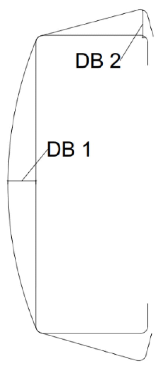
Figure 3.
Definition of geometric imperfections.
Global buckling, denoting the instability or mode of failure of an entire cold-formed steel member, such as a beam or column, induced by compressive or bending stresses [28,29,30,31,41,43], poses a critical risk that can lead to the collapse of the entire structure. In the investigation of CFS fasteners, it is evident that spring spacing exerts no influence on local buckling and only a negligible effect on distortional buckling. Nevertheless, springs play a pivotal role in averting global buckle. As per the findings, the dispersed spring presumption holds validity only when the ratio of fastener spacing to the half-wavelength for global buckling is less than 0.25 [49].
In the context of multi-limb CFS stub columns, the most prevalent failure mechanisms are identified as DB and LB [50]. These columns, comprising a single component that is C-section and U-section and connected together by screws that drill their own holes, demonstrate distinctive failure patterns. Conversely, while the modified slenderness technique is generally conservative, it may deviate by approximately 10%, being less conservative for built-up CFS stub columns arranged in a back-to-back configuration [51]. These findings underscore the significance of considering global buckling in the design and analysis of cold-formed steel structures.
2.4. Factors That Affect Strength
In an effort to mitigate distortional buckling (DB), some manufacturers have employed sophisticated edge stiffeners by adding extra return lips to the flange lips [32]. This preference for lipped portions is grounded in their higher estimated ultimate load-bearing capability [26].
The study findings reveal that, on average, the axial strength of built-up unlipped members is inferior to that of built-up lipped channel members [52]. Additionally, for thinner elements, the yield stress significantly surpasses the lip buckling strength [36]. The most prevalent form of edge stiffener utilized in thin-walled sections is the lip [18]. Notably, lipped channel sections with stiffened webs exhibit a notable advantage in withstanding local buckling (LB) and are correlated with higher stress levels in DB compared to channel sections without stiffeners [53]. The shear buckling forms of lipped channel beam (LCB) sections, featuring return lips, share similarities with plain LCB sections undergoing single buckling half-waves. However, sections with web stiffeners manifest two buckling half-waves, resulting in a reduction in the length of the buckling half-waves [54].
The longitudinal lip section situated in the center of the compression flange effectively limits the slenderness of the plate, functioning as stiffeners and substantially enhancing the LB strength of the members [55]. Consequently, while other parts of stiffened built-up columns (SBC) composed of lipped members may fail due to a similar buckling phenomenon, the plate element LB mostly occurs at the lip regions [56]. Additionally, rectangular stiffeners with lip channel elements carry more weight than rectangular stiffeners without a lip, and V stiffeners with lip channel members carry more load than V stiffeners without a lip [57].
Various factors, including the cross-sectional area of different profiles, the yield strength () of steel, and the thickness (t) of the CFS, directly relate to axial load capacity [58]. Interestingly, the torsion rigidity remains unaffected by the fasteners [59]. Thickening plates, however, lead to a decrease in the interplay between flexural and local buckling [60].
The maximum slenderness ratio significantly influences the structural behavior of the columns [61,62]. Enhancing the built-up column’s strength and stability is achieved by widening the flange. On the weak axis, the column’s eccentric axial compression strength declines more rapidly than on the strong axis [62]. Moreover, reducing the distance between webs connecting fasteners strengthens the flange’s rotational stiffness, resulting in larger critical distortional buckling stresses when compared to single-sigma sections [63].
The spacing of screws in multi-limb cold-formed steel stub columns, composed of singular components in the forms of C and U joined together using self-drilling screws [50], does not significantly affect the nominal axial resistance, critical axial strength, or CFS stub columns’ stiffness with several limbs.
Regarding short sigma CFS columns back-to-back joined by fasteners on their webs, the breakdown mechanism is mostly determined by the DB of the flanges. For intermediate-height columns, failure modes predominantly include interactional overall sectional buckling, encompassing both LB and DB. In lengthy columns, overall buckling emerges as the principal failure mode. Notably, in sections with greater web recess height-to-thickness ratio values, a transition occurs in the buckling modes, shifting from DB to LB when the distance between fasteners is reduced [64].
The introduction of diagonal bars in the flexure and shear zones of back-to-back CFS I beams welded to the web with diagonal reinforcing rods enhance the beam’s load resistance compared to beams without diagonal bars. The presence of diagonal bars increases the load-bearing capacity by 1.1 times when present in the shear zone alone and by 1.4 times when present in both the flexure and shear zones compared to beams without diagonal bars [63]. These comprehensive insights underscore the intricate relationship between edge stiffeners, lip configurations, material properties, and the structural performance of built-up cold-formed steel members.
3. Impact of Inside Radius
The modification of the mechanical characteristics of produced sections is significantly influenced by R/t ratios, with the ratio of the inner radius to thickness (R/t) being a prominent parameter affecting the mechanical characteristics of corners in cold-formed steel (CFS) sections. This ratio, exemplified by the inner radius to thickness (R/t), is among numerous parameters that often impact the mechanical characteristics of CFS corners. Consequently, within a specific material context, a reduction in the R/t ratio is associated with a corresponding increase in the yield stress, where R represents the interior fillet radius, and t denotes the sheet thickness [28,30,65]. Conversely, smaller values of (R/t) indicate a higher level of cold work occurring at a corner. It is noteworthy that the corner radius exerts a more pronounced effect on local buckling than on distortional or global buckling [66].
Adjacent portions should maintain a maximal internal fillet radius-to-thickness ratio (/t) less than or equal to eight (see Figure 4) [29]. Ensuring a minimum internal radius (r) of 5 × t is crucial. According to EN1993-1–3 standards, tests are recommended to evaluate cross-sectional resistance when the internal radius (r) exceeds 0.040 × (t × E)/, where the variable E represents the modulus of elasticity of the steel material [31]. These considerations highlight the intricate relationship between R/t ratios, material properties, and the mechanical behavior of cold-formed steel sections, particularly emphasizing the pivotal role of corner characteristics in influencing local buckling.
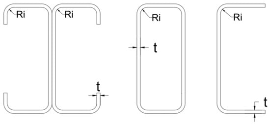
Figure 4.
A description of the Ri/t ratio correlation for the following: built-up back-to-back open section, single close section, and single open section, respectively.
3.1. Effects of Various Geometric Shapes
Cold-formed steel (CFS) sections exhibit diverse types based on their construction and configuration, which encompass single sections, closed built-up sections, and open built-up sections (see Figure 5). The choice of section type has a significant impact on structural performance and load-bearing capacity. Super-sigma and folded-flange sections were found to have substantial flexural capacity augmentation, approximately 65% and 60%, respectively, for an equivalent amount of material. A detailed investigation into the overall performance of super-sigma members subjected to bending, shearing, and web-crippling movements revealed their efficiency [67]. Conversely, closed-up columns demonstrate the capacity to support a greater weight than open-up sections, with the load-bearing capacity improving as the section’s thickness increases [68]. The flexural stiffness and bending capacity of corrugated web-built-up beams can be significantly enhanced by increasing the thicknesses of both the web and the shear panel [69].

Figure 5.
Closed and open built-up cold-formed steel sections [59].
As the maximum slenderness ratio [61] increases, the axial compressive capacity [62] and rigidity of CFS columns, comprising four C-members, undergo a dramatic reduction. For instance, when the average slenderness ratio increases from 6 to 97, a consequential reduction is observed in the ultimate strength, decreasing from 266 kN to 189 kN. Within the range of screw spacing from 150 mm to 450 mm, there is minimal variation in the axial compressive capacity and rigidity of such columns. Notably, a reasonable fastener spacing of 150–300 mm allows each component of the column to function effectively together, while the capacity for axial compression increases as the ratio between the width and thickness of the flange decreases [61]. Conversely, the spacing of screws had an impact on the flexural capacity [70].
The placement of screws in component members to form built-up portions, such as 4C and 3C, was observed to impact the geometry of the elements. While additional fasteners generally elevate the composite action level in built-up members, the screw installation process may deform the specimen geometry, potentially affecting the strength of the member. Importantly, it was noted that the ultimate capacity of test columns was not significantly increased by employing more screw rows [71]. These insights underscore the diverse characteristics of CFS sections and the nuanced interplay between geometric considerations, material properties, and load-bearing capacities in different configurations. These findings underscore the nuanced relationship between the type of CFS sections, their construction, and the influence of various parameters on their mechanical characteristics and performance. However, it has been shown that an open-section beam exhibits a larger ultimate load capacity compared to a closed-section beam [72]. On the other hand, based on the findings of the experiments [73], it can be concluded that the back-to-back linked built-up beam section offers a greater flexural capacity than the face-to-face built-up section. Alternatively, built-up sections are composed by joining multiple individual sections through fastening mechanisms such as welding, screwing, or bolting. Built-up members [59] can be further categorized into closed and open built-up sections, as illustrated in Figure 5.
3.2. Web Crippling and Holes of CFS Elements
Web crippling, illustrated in Figure 6, represents a structural failure mode wherein the web, the vertical section between flanges in a built-up or single-section member, undergoes localized buckling or yielding due to excessive loads or pressure. This phenomenon can significantly impact the stability and load-carrying capability of the steel member [74,75]. In this study, rectangular hollow flange channel beams (RHFCBs) secured with rivets were subjected to two load scenarios: End One Flange (EOF) and Interior One Flange (IOF). Experimental tests were conducted on securely attached flanges, revealing respective increases of 39.0% and 5.0% in web crippling capabilities for EOF and IOF load instances [8].
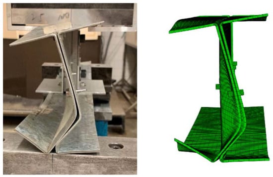
Figure 6.
Web crippling of back-to-back double U-members [76].
Recommendations suggest maintaining an e/H ratio of no more than 0.3 for built-up I-sections to prevent substantial reductions in web crippling strength. Here, e represents the space between the outer surface of the flanges and the center of the screw, while H denotes the entire height of the web [76].
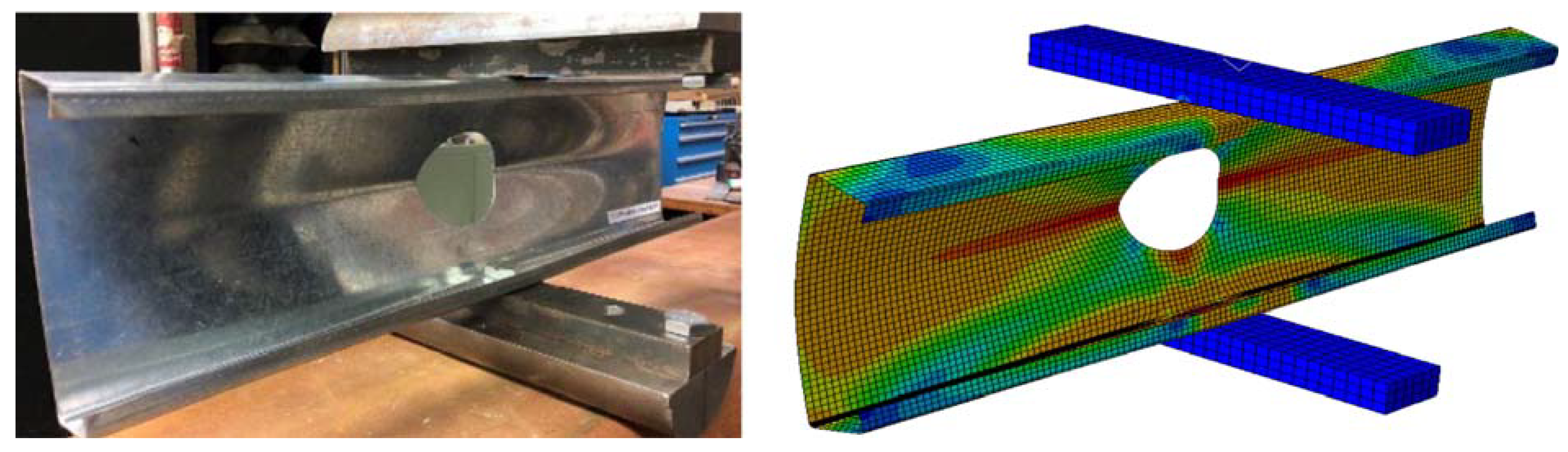
On the contrary, web holes, depicted in Figure 7, entail intentional voids created within the web of a cold-formed steel (CFS) section. These openings, varying in shapes and sizes, often serve specific purposes such as weight reduction, accommodating services, or facilitating connections with other structural elements. The effects of web holes are crucial, influencing the structural behavior and integrity of these sections. This analysis involves assessing factors like stress concentration around the hole, the impact on overall stiffness, and the section’s capacity to withstand loads [74]. The shear capability of sections decreased with increasing web hole diameter, while the shear capacity rose with the distance of web holes from the bearing plate [45].

Figure 7.
Experimental and numerical deformation of the C-section with web holes [77].
When the opening diameter-to-height depth ratio (a/h) increased from 0.0 to 0.80, the axial strength of back-to-back aluminum alloy columns decreased by 15.0 to 20.0%. Additionally, the average reduction in axial strengths was 32.0% for plain members and 36.0% for members with a central web hole. Furthermore, upon increasing the mean adjusted slenderness ratio ( from 56.0 to 250.0, the columns’ axial strength exhibited an average increase of 10.0% for plain elements and 13.0% for parts with a centered web hole when the numerical value of the screw was altered from two to five [78].
Experimental test findings indicated that web holes had only a minimal effect on the beams’ bending stiffness [79]. These comprehensive findings shed light on the intricate dynamics of web crippling and the impact of web holes on the structural behavior of cold-formed steel sections, emphasizing the need for careful consideration in design and analysis.
3.3. Impacts of End Fastener Groups (EFGs) and End Conditions on CFS Sections
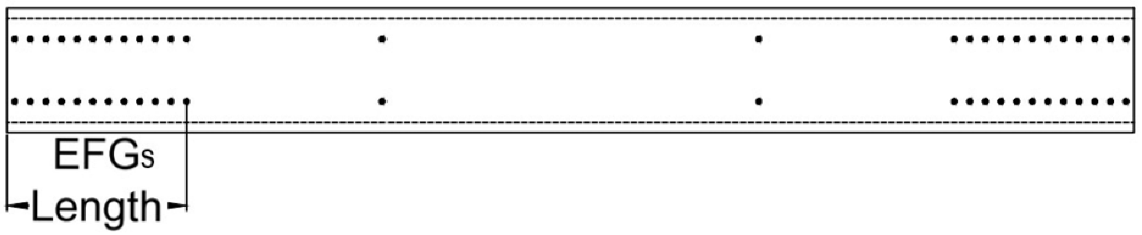
The weight-carrying capacity of CFS columns is influenced by various factors, including the addition of end fastener groups (EFG) (see Figure 8). It is noted that the column’s load-carrying capacity diminishes as the height of the web increases [80]. Interestingly, local buckling capacity and column strength appear to be minimally affected by fastener spacing or the presence of EFGs. The test results suggest that factors such as fastener spacing and EFGs may not always be as critical as the end bearing condition. When buckling in the web occurs, the arrangement of fasteners does not necessarily increase local buckling capacities or column strengths. Instead, it has an impact on the placement of local half-wavelengths [81]. In scenarios where the load is delivered through stiff end platens, EFGs and end welds exhibit little impact on capacity. Although EFGs enhance the capacity and rigidity of members, the inclusion of extensive end fastener grouping, even in cases where buckling occurs due to minor-axis flexure, shows a restricted improvement in load-carrying capacity [59,60].

Figure 8.
End fastener groups’ (EFGs’) layout.
For screws to function effectively within specified end fastener groups (EFGs), they must be positioned longitudinally at intervals no more than four times their diameter. This spacing should be maintained over a distance equivalent to one and a half times the largest possible width of the built-up CFS elements [41]. The utilization of EFGs on columns, particularly built-up back-to-back steel columns, proves successful primarily for the flexural buckling mode and is less useful for the local buckling mode [82]. Columns with EFGs may experience up to a 33 percent increase in capacity compared to those without EFGs, along with enhanced member reliability indices. However, it is worth noting that buckling capacity and flexural deformations, as well as the effectiveness of the EFG, are marginally lessened when local buckling (LB) interacts with global buckling (GB) [83].
The influence of end conditions on CFS columns is noteworthy, especially in the context of global buckling. Modifying end support conditions has the potential to substantially mitigate the complexity of corrugated web-built-up beam support and its associated cost without a significant decrease in beam performance related to its rigidity and bending capacity [69]. It is observed that for fixed-end columns, AISI and Eurocode strength estimations are conservative [60]. Interestingly, there is no discernible relationship between end conditions, normal web interconnections, and sheathing concerning local buckling of CFS columns. The minimal influence of end circumstances and web connectivity on distortion buckling (DB) is noted, but the presence of sheathing significantly improves DB, as measured by adequately defined spring stiffnesses [84].
4. Equations for Determining Various Buckling Modes in Columns and Beams [28,29,30,41]
4.1. Members in Compression
4.1.1. Global Buckling (GB)
The following equations below are used to find global buckling of cold-formed steel sections:
where is the crucial compressive load for GB, is the GB nominal axial strength, stands for yield stress, is critical elastic global buckling (GB) stress, and is global flexural stress or global compressive stress.
4.1.2. Distortional Buckling (DB)
The following equations below are used to determine the distortional buckling of CFS members:
where is the critical elastic DB column load, is the DB nominal axial strength, and the nominal axial strength is denoted by .
4.1.3. Local Buckling (LB)
The following equations below are used to find local buckling of CFS elements:
where is the crucial compressive load for LB in elastic, and is the LB nominal axial strength.
where .
4.2. Members in Flexure
4.2.1. Global Buckling (GB)
The following equations below are used to find global buckling of CFS members:
where is the crucial bending moment for global buckling in elastic, is the global buckling nominal flexural strength, and the term refers to the moment at which a member yields; in the first yielding, the complete unreduced section’s elastic section modulus with respect to the extreme fiber is , while the full unreduced section’s elastic section modulus with respect to the extreme compression fiber is .
4.2.2. Distortional Buckling (DB)
The following equations below are used to determine the distortional buckling of CFS elements:
where is the crucial bending moment for distortional buckling in elastic, is the DB nominal flexural strength, and is the nominal flexural strength.
4.2.3. Local Buckling (LB)
The following equations below are used to find local buckling of CFS sections:
where is the crucial bending moment for LB in elastic; is the LB nominal flexural strength.
where .
5. Validation of FE Models
In this section, a comparative analysis of the accuracy of Finite Element Method (FEM) simulations conducted using ABAQUS, Finite Strip Method (FSM) simulations employing CUFSM [85], and experimental test results [4] is undertaken (see Figure 9). All data utilized for this meticulous comparison are extensively documented (see Table 1).
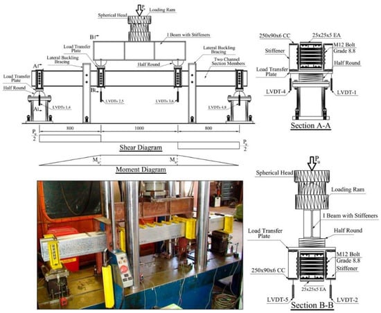
Figure 9.
Real experimental test configuration for pure bending testing [4].

Table 1.
Specimen properties and results of plain C-channel sections.
The analysis revealed the remarkable precision of these tests. It is noteworthy that the slight disparities observed among the three datasets can be attributed to the inherent methodological differences between the software tools employed. Specifically, ABAQUS is optimized for FEM analysis, whereas CUFSM is tailored for FSM analysis.
Upon examination, it is evident that the mean values for in the Test/FE and FS/FE datasets are 0.989 and 0.992, respectively. Similarly, for , the mean values in the Test/FE and FS/FE datasets are 0.974 and 0.979. Furthermore, the coefficient of variation (COV) for in the Test/FE and FS/FE datasets is calculated to be 0.00419 and 0.00534, respectively. As for , the COV values are 0.017 and 0.004286.
These small COV values indicate the high accuracy and consistency of the data across the different analysis methods.
To juxtapose the Finite Element Method (FEM) outcomes with experimental tests [86], four fixed-end beams underwent a comprehensive comparison in this study. The material properties were uniform across all beams, with a yield strength () of 271 MPa and a modulus of elasticity (E) of 188 GPa.
Table 2 presents the findings, revealing an average difference of merely 3.4% between the results obtained from experimental tests and FEM. This minimal disparity underscores the accuracy of the numerical simulations conducted in this research. Consequently, the Abaqus software emerges as a reliable tool for the analysis of laboratory tests.
Table 2.
Comparison of nominal buckling moments in experimental and finite element modeling (FEM) for fixed-end beams.
6. Numerical Modelling
This research included a thorough examination of the flexural and compressive characteristics of individual cold-formed steel (CFS) sections by an exhaustive Finite Element (FE) analysis, focusing specifically on liner buckling. The analysis was carried out using the ABAQUS FE software package, version 2023. To incorporate the effects of geometric imperfections, eigenvalue buckling analysis was employed as the primary method of analysis.
Initially, the CFS sections were created within the software environment. The modeling process involved selecting 3D as the Modeling Space, choosing the Deformable option, and opting for Shell as the Shape. Subsequently, an extrusion method was used to create the sections, ensuring uniformity in their geometrical characteristics. Material properties were assigned to these sections using the Create Material command. The material specification included parameters such as steel type (S355), mass density (7.849 ), elasticity (Young’s modulus: 210,000 MPa, Poisson’s ratio: 0.300), and plasticity characteristics, with a yield stress of 355 MPa.
For structural integrity, reference points (RPs) were strategically created at both ends of each section. Coupling constraints were applied to link these RPs with their respective sections (see Figure 10). Subsequently, a linear perturbation analysis was executed with a focus on buckle behavior. To simulate real-world conditions, a concentrated force of one Newton was applied to the top of the columns, complemented by a one-Newton*millimeter moment applied to the beams. The boundary conditions for the beams and columns were set as Simply Supported (see Figure 10).
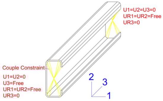
Figure 10.
Boundary conditions of specimens.
For computational efficiency, three-dimensional S4R shell elements with reduced integrations were employed throughout the analysis, leading to a decrease in the amount of time required for calculation. A mesh size with consistent dimensions of 5 × 5 mm was implemented across the entire set of structural members.
Upon completion of the FE analysis, eigenvalues were determined, yielding critical elastic loads and moments for both columns and beams. Specifically, the analysis provided critical elastic loads and moments for the three types of buckling are global (GB), distortional (DB), and local (LB) for both columns and beams.
In accordance with established industry standards and guidelines, including AISI S100-16 [28,41], AS/NZS 4600-2018 [29], and Eurocode 3 (part-1–3) [31], a comprehensive evaluation was performed. This assessment encompassed the determination of nominal axial loads for global buckling (), distortional buckling (), and local buckling (), as well as the calculation of available axial loads () for columns. Similarly, nominal flexural moments for global buckling (), distortional buckling (), and local buckling (), were computed, alongside the assessment of available flexural moments () for beams.
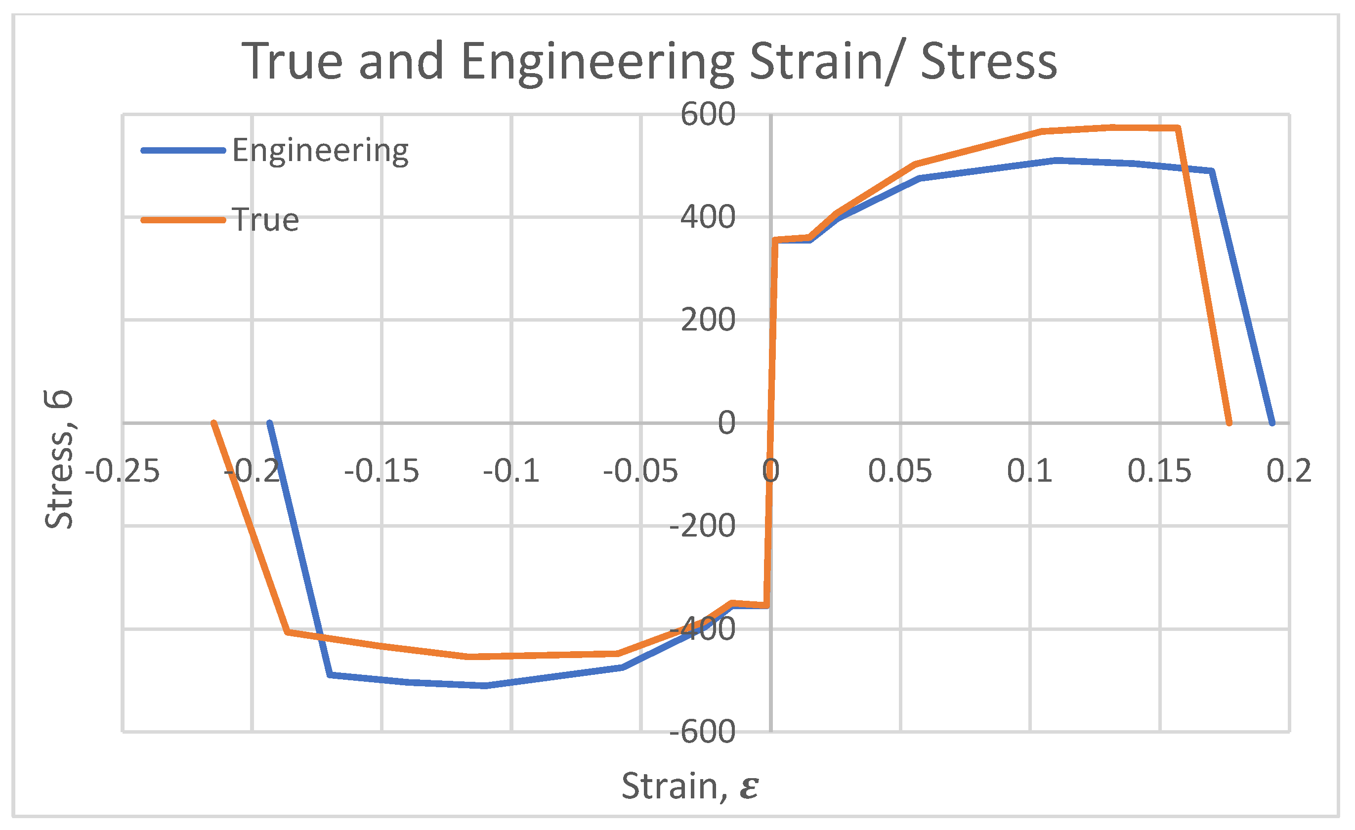
In utilizing the Abaqus software, it was imperative to convert engineering strain–stress to true strain–stress, as illustrated in Figure 11. This conversion was achieved through the application of Equations (28) and (29).

Figure 11.
The relationship between strain (ε) and stress (σ).
7. An Analysis of the Effects of Lip Length on Various Types of Column and Beam Buckling
To investigate the influence of lip length on C-sections, particularly in relation to local buckling, distortional buckling, and global buckling, a set of five distinct cross-sections were employed. The study involved the creation of 25 column and 25 beam examples, as illustrated in Figure 12. Initial construction of these 50 models was conducted through the Finite Element Method (FEM). Subsequently, critical values for local buckling load (), distortional buckling load (), and global buckling load () were determined for columns, along with critical local buckling moment (), critical distortional buckling moment (), and critical global buckling moment () for beams.
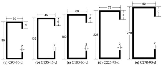
Figure 12.
Gross section properties of C-sections with lips. * the lip length (d) ranges from 0 to 30 mm, encompassing values of 0, 10, 15, 20, 25, and 30 mm. * none of the graphs are drawn to scale. * all dimensions are presented in millimeters.
Following the acquisition of critical buckling loads and moments, as detailed in Table 3 and Table 4, respectively, the investigation proceeded to employ the direct strength method (DSM). This phase involved the determination of nominal values, including nominal local buckling load (), nominal distortional buckling load (), nominal global buckling load (), and the available axial strength () for columns. Additionally, the nominal local buckling moment (), nominal distortional buckling moment (), nominal global buckling moment (), and available tensile strength () for beams were established.
Table 3.
Analysis of buckling types in C-section columns with lips.
Table 4.
Analysis of buckling types in C-section beams with lips.
In the context of C-section columns, as detailed in Table 4, the impact of lip length (d) on structural behavior is noteworthy. Notably, an increase in lip length exhibits a substantial influence on the critical elastic distortional buckling load per unit area (/A), showcasing a significant enhancement. This observation is critical for comprehending the performance of C-section columns under different loading conditions.
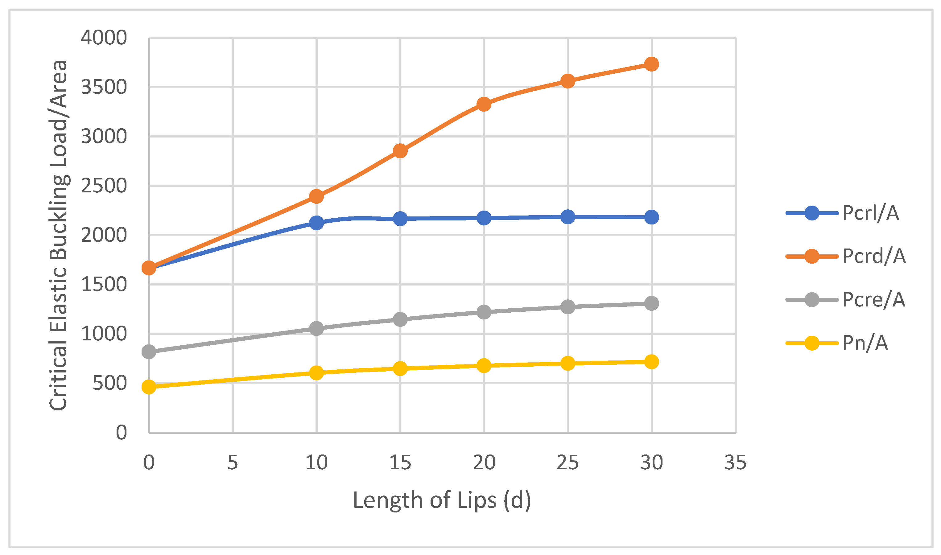
Furthermore, a discernible correlation exists between (/A) and lip length (d), as well as (/A) and (d), and (/A) and (d). In essence, the extension of lip length directly corresponds to an increase in critical elastic local buckling, critical elastic global buckling, and nominal buckling, as depicted in Table 4 and Figure 13. This outcome holds considerable significance for researchers and practitioners in the steel structure domain. It underscores that the augmentation of lip length enables columns to bear increased loads while mitigating the risk of the three distinct types of buckling.

Figure 13.
Examining the influence of lip length (d) on different forms of the critical elastic buckling load.
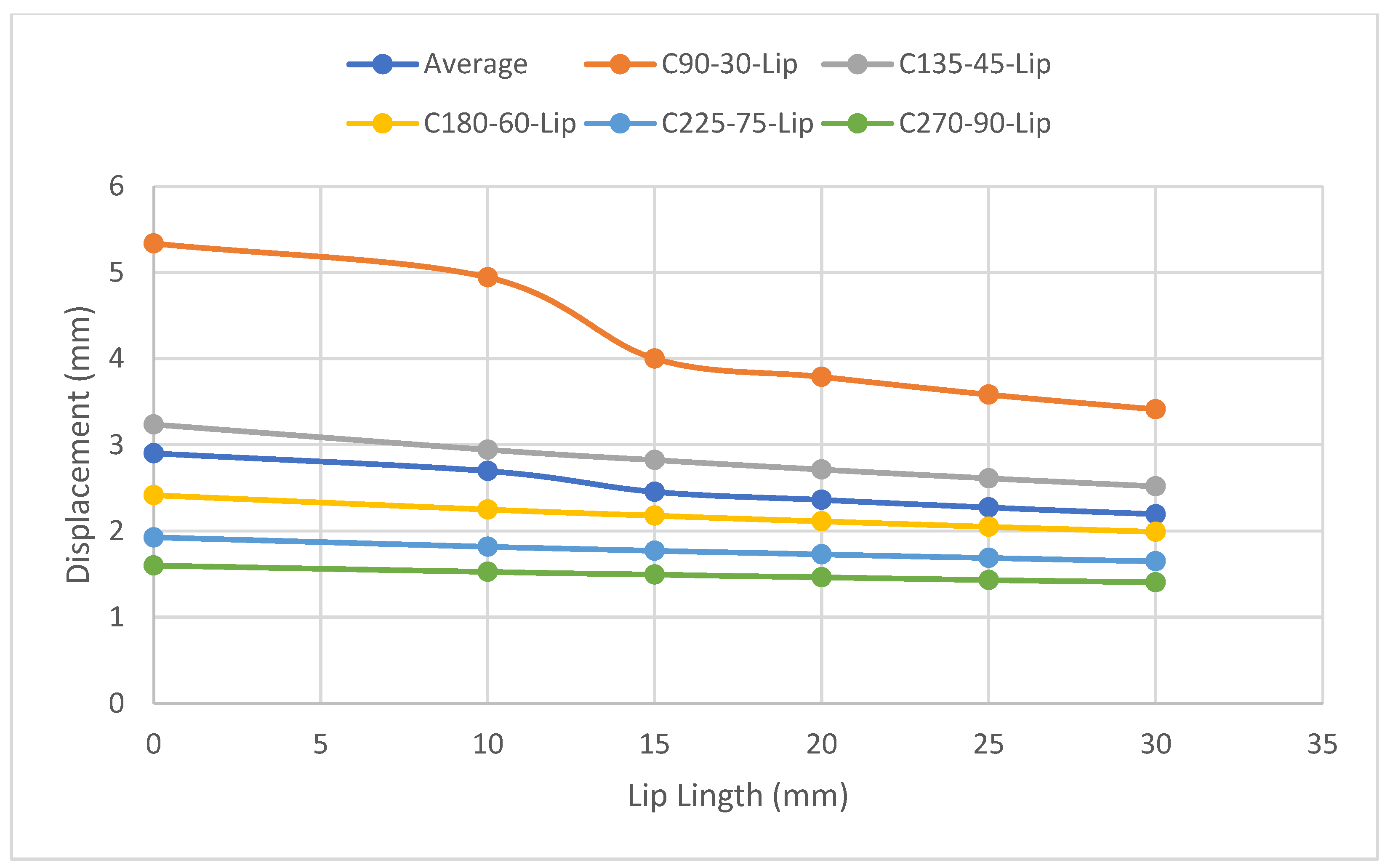
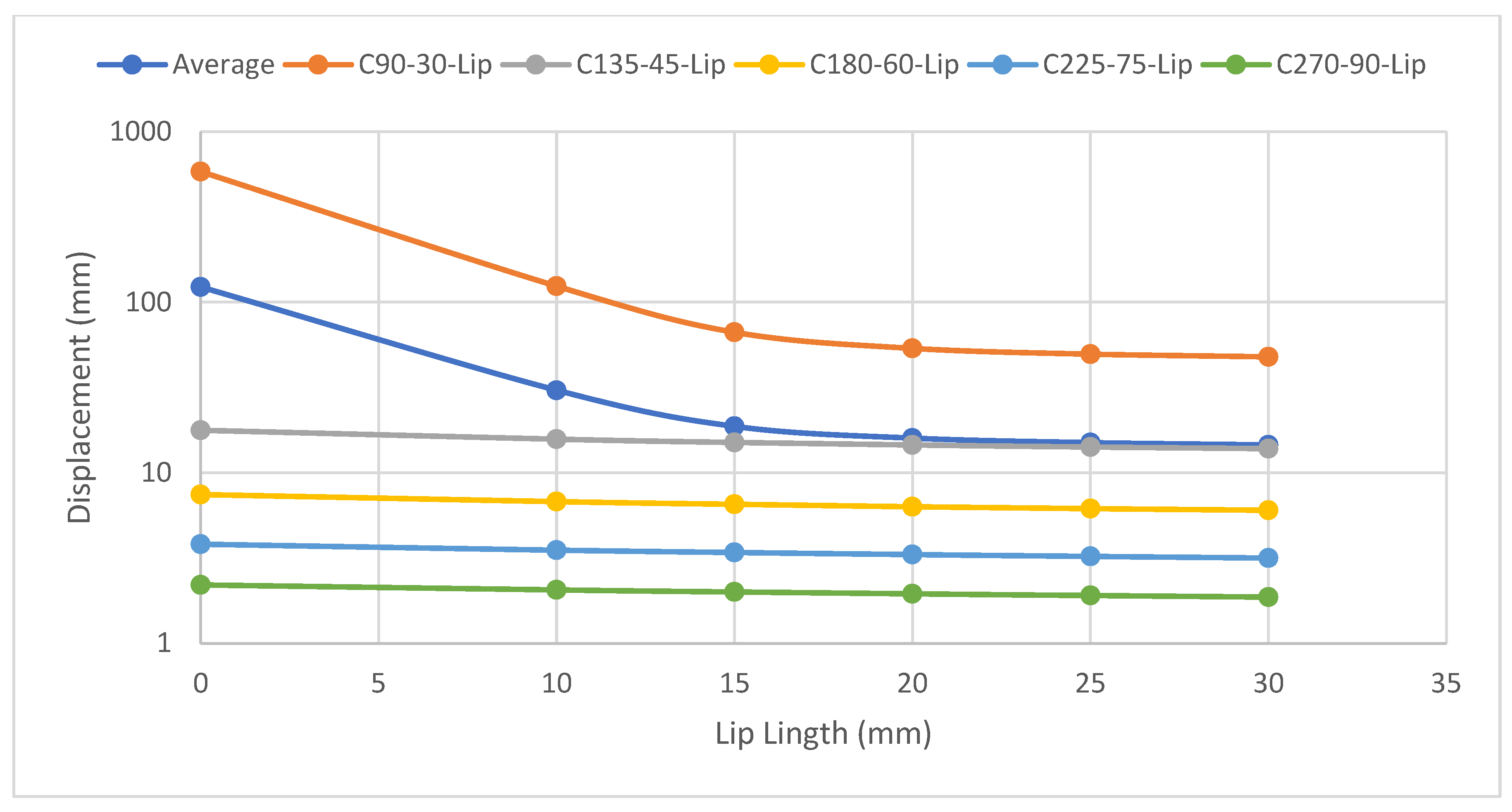
To further assess the relationship between lip length and displacement, a load of 100 kN is applied individually to each of the 25 columns. Figure 14 illustrates an inverse relationship between lip length and flexural displacement, signifying that an increase in lip length corresponds to a decrease in the flexural displacement of the columns. This insight contributes valuable knowledge to the understanding of the interplay between geometric parameters and the structural response of C-section columns, offering practical implications for optimizing structural performance.

Figure 14.
The relationship between lip length and the displacement of columns.
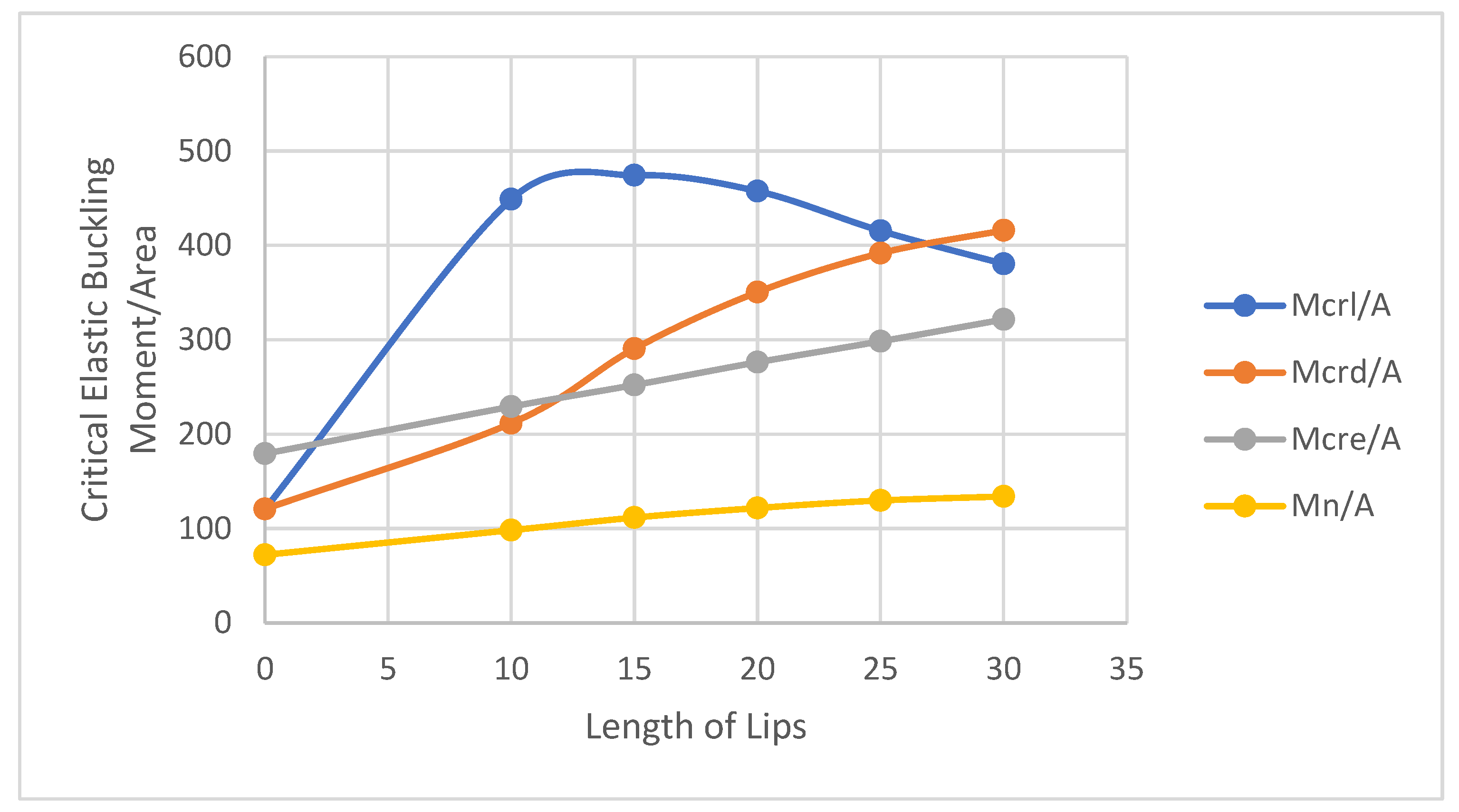
In the examination of the influence of lip length on single C-section beams, the comprehensive analysis, as delineated in Table 4 and Figure 15, reveals profound effects on all three distinct types of buckling. Notably, an increase in lip length demonstrates a direct correlation with critical distortional moment and critical global moment. Specifically, this augmentation manifests as a substantial increase in critical elastic distortional buckling moment/area (/A) and critical elastic global buckling moment/area (/A), elucidated by the data presented in Table 4.
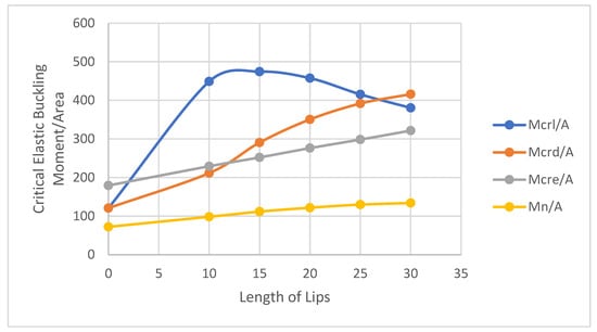
Figure 15.
Examining the influence of lip length (d) on different forms of the critical elastic buckling moment.
Concerning nominal moment, an escalation in lip length corresponds to a proportional increase in the elastic nominal buckling moment. The examination of local buckling nuances this relationship. Initially, as the lip length varies from 0 mm to 10 mm, there is a significant increase in critical elastic local buckling moment/Area (/A). However, subsequent increments in lip length to 15 mm, 20 mm, 25 mm, and 30 mm, respectively, resulted in a marginal decrease compared to the moment when the lip length was 10 mm.
In exploring the relationship between lip length and flexural displacement in beams, a moment of 4 kN·m was uniformly applied to all beams. Figure 16 illustrates a discernible inverse correlation between flexural displacement and lip length. This indicates that an increase in lip length corresponds to a decrease in flexural displacement, representing a noteworthy achievement in steel engineering. The strategic extension of the lip length emerges as a simple yet effective method for enhancing the load-carrying capacity of beams.
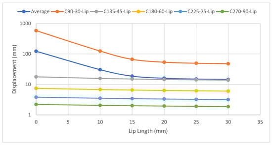
Figure 16.
Investigating the relationship between lip length and displacement of beams.
8. Analysis of the Effects of Inside Radius/Thickness on Various Buckling Modes in Columns and Beams
In the exploration of the influence of inside radius/thickness on C-sections, with a specific focus on local buckling, distortional buckling, and global buckling, a comprehensive set of nine distinct cross-sections were strategically employed. The study encompassed the creation of 63 column and 63 beam examples, as visually represented in Figure 17. The initial construction of these 126 models was meticulously executed through the Finite Element Method (FEM). Subsequent to this modeling phase, critical values for local buckling load (), distortional buckling load (), and global buckling load () were determined for columns. Similarly, critical local buckling moment (), critical distortional buckling moment (), and critical global buckling moment () were established for beams. Following the acquisition of these critical buckling loads and moments, meticulously documented in Table 5 and Table 6, respectively, the study transitioned to the determination of nominal values. This involved defining the available axial strength () for columns and establishing the available tensile strength () for beams.
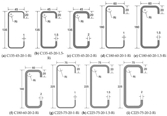
Figure 17.
Specimen cross-sections with inside radius (Ri). * the inside radius-to-thickness ratio (Ri/t) varies within the range of 0 to 6 mm, including values of 0, 1, 2, 3, 4, 5, and 6 mm. * the graph is not drawn to scale. * all dimensions are expressed in millimeters.
Table 5.
Analysis of buckling types in C-section columns with inside radius (Ri).
Table 6.
Analysis of buckling types in C-section beams with inside radius (Ri).
It is imperative to note that all beams and columns utilized in this study adhered to a standardized length of 3000 mm. This uniformity in length among specimens ensured consistency in the experimental setup, facilitating meaningful comparisons across different sections. Furthermore, the precision of the study was upheld by meticulous measurements of all dimensions and lengths, conducted in millimeters, ensuring accuracy and reliability in characterizing the specimens.
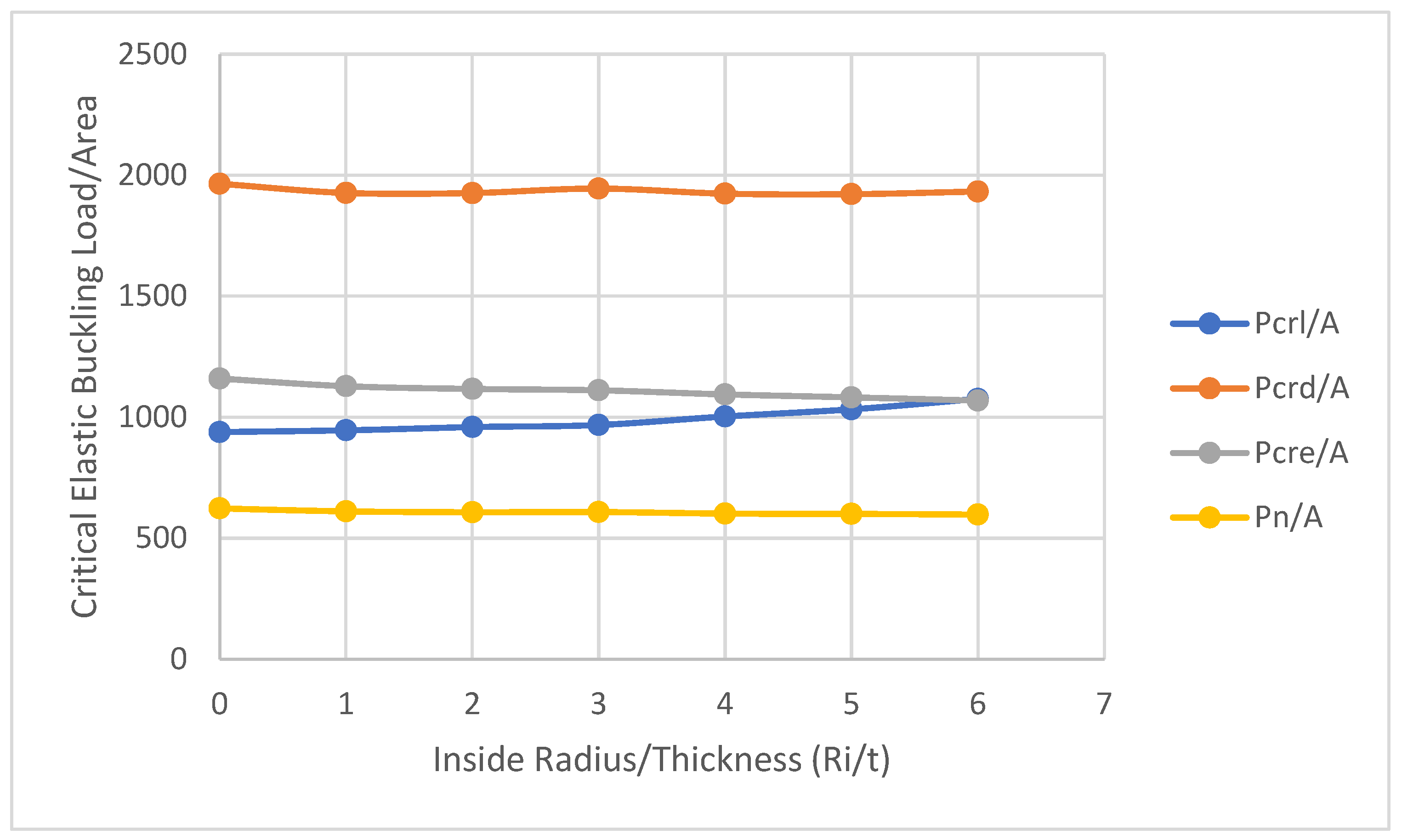
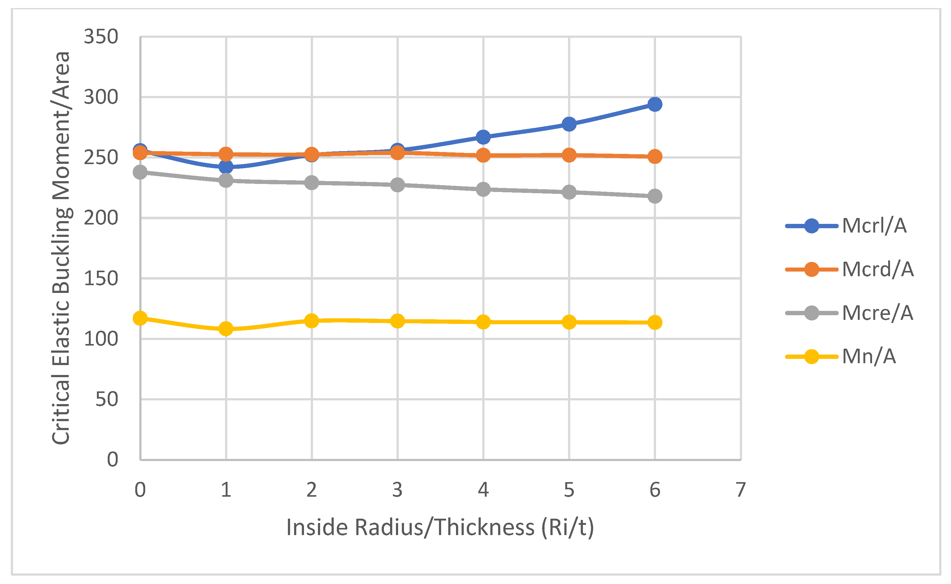
Upon meticulous recording of the column data in Table 5 and beam data in Table 6, followed by a comprehensive comparison of all gathered data and results, the following observations emerged: The ratio of inside radius/thickness (Ri/t) demonstrates a direct correlation with the critical elastic local buckling load (/A) and critical elastic local buckling moment (/A). An increase in the Ri/t ratio corresponds to a slight increase in /A and an increase in /A, as illustrated in Figure 18 and Figure 19.
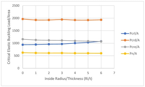
Figure 18.
Impact of inside radius/thickness on various buckling modes in columns.
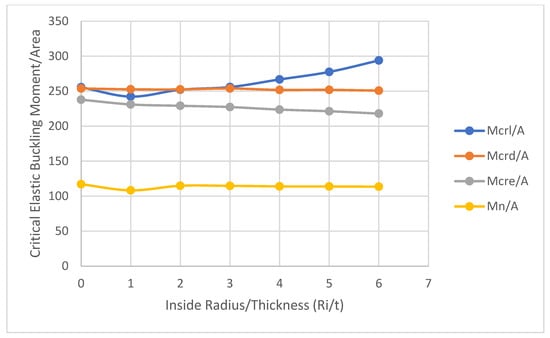
Figure 19.
Investigation into the impact of inside radius/thickness on various buckling modes in beams.
Conversely, the ratio of inside radius/thickness (Ri/t) exhibits an inverse relationship with the critical elastic global buckling load (/A) and critical elastic global buckling moment (/A). Specifically, an increase in Ri/t results in a minor decrease in the ratios /A and /A.
In the realm of distortional buckling, the Ri/t ratio demonstrates no discernible effect on the critical elastic distortional buckling load (/A) and critical elastic distortional buckling moment (). These findings provide valuable insights into the nuanced relationships between the inside radius/thickness ratio and critical buckling characteristics, contributing to a deeper understanding of the structural behavior under various loading conditions.
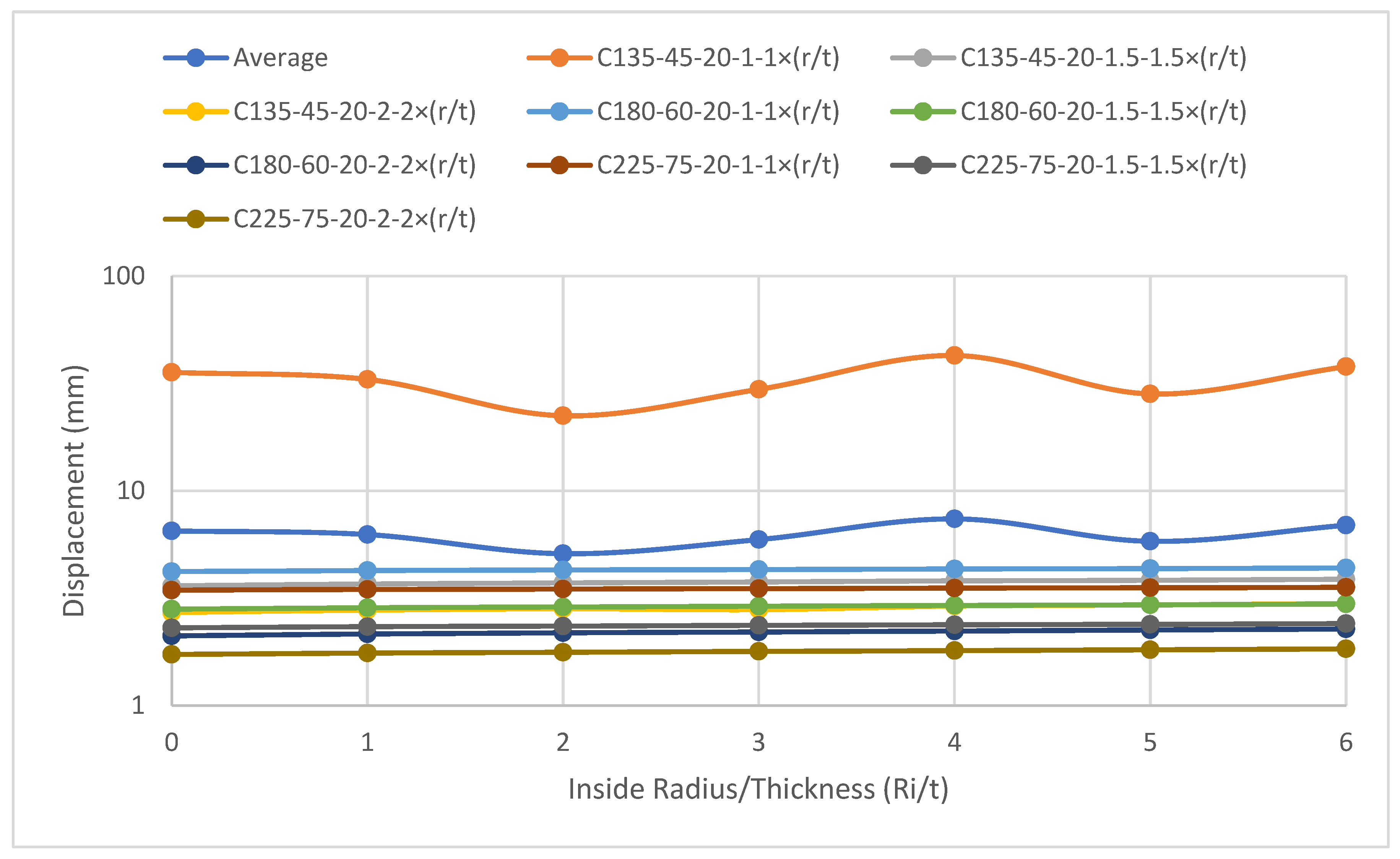
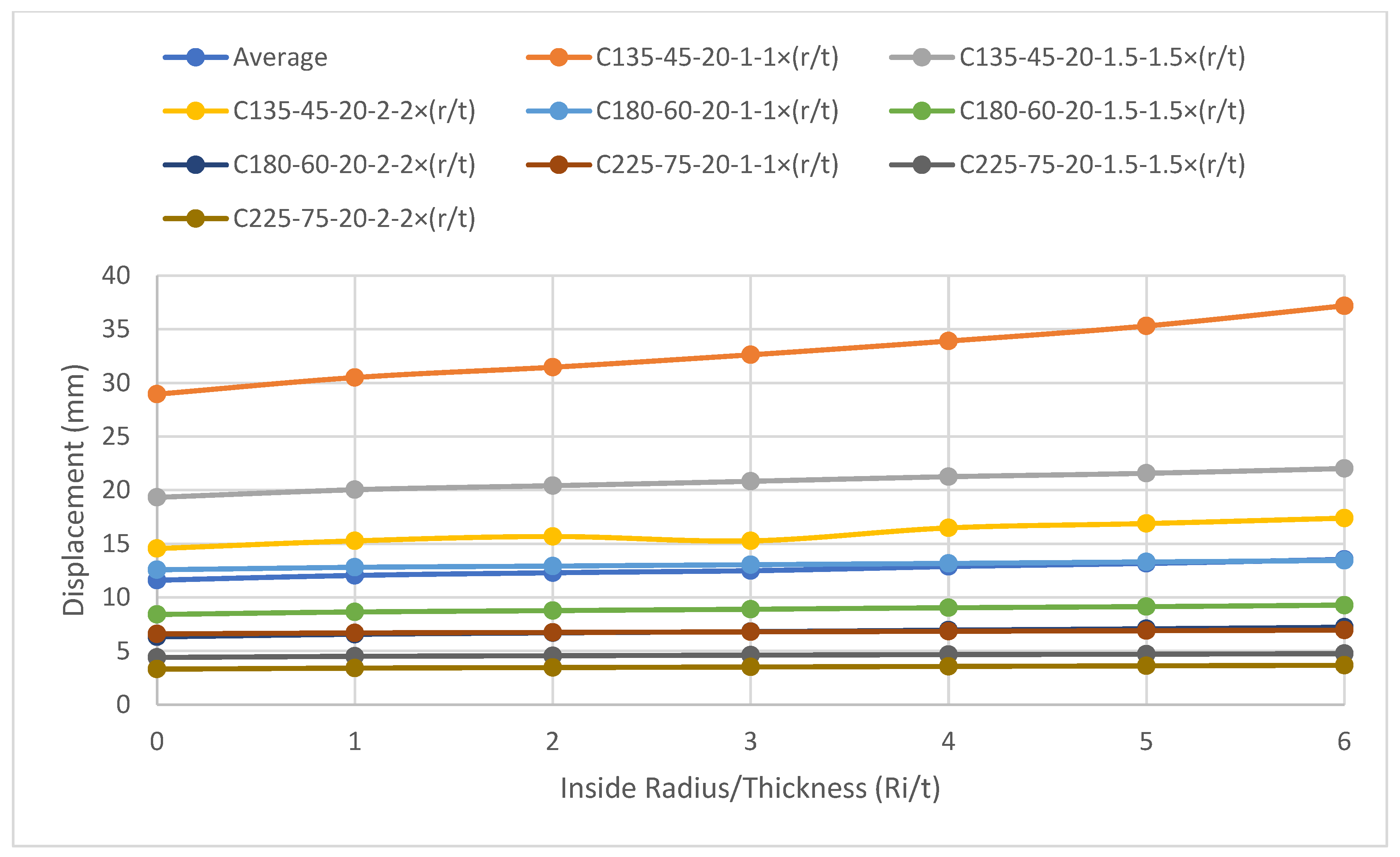
In examining the connection between displacement and the Inside Radius/Thickness (Ri/t), a load of 100 kN was individually applied to each column, and a moment of 4 kN·m was applied to each of the beams. The graphical representation in Figure 20 and Figure 21 indicates that, in general, the inside radius/thickness (Ri/t) minimally influences or has no discernible impact on the flexural displacement of both beams and columns.
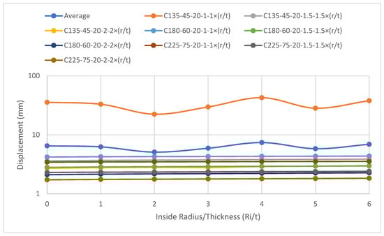
Figure 20.
Influence of inside radius/thickness on the axial displacement of columns.
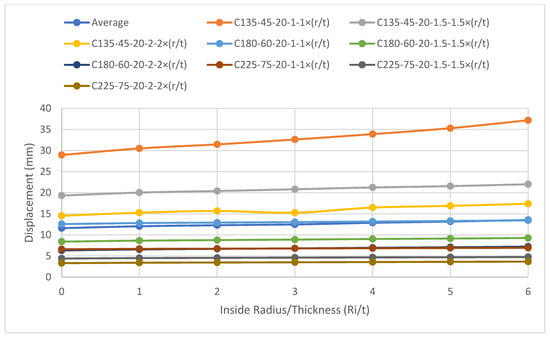
Figure 21.
Investigating the influence of inside radius/thickness on the flexural displacement of beams.
An additional benefit associated with the inside radius/thickness (Ri/t) is its facilitation of section creation in factories. This aspect underscores the practical advantage of Ri/t in manufacturing processes, contributing to ease and efficiency in the production of structural sections.
9. Conclusions
This study employed the Finite Element Method (FEM) to conduct 176 tests on single C-section cold-formed steel (CFS) columns and beams. The analysis extended to various design standards, including AISI-S100 [28,41], AISI-S240 [35], AS/NZS-4600 [29], and Eurocode 3 Part 1-1 [31]. The primary objectives were to establish the relationships between critical and nominal buckling load and moment with lip length (d) and the ratio of inside radius to thickness (Ri/t). The key findings for an equivalent amount of material can be summarized as follows:
With the progressive increase in (d) for columns (from 0 mm to 30 mm), a significant rise (about 124%) is observed in the critical elastic distortional buckling load (), accompanied by an increase in the critical elastic local buckling load () (approximately 31%) and the critical elastic global buckling load () (around 60%). Furthermore, there is an overall augmentation (close to 55%) in the nominal axial strength ().
Similarly, with an increasing (d) for beams (spanning 0 mm to 30 mm), a substantial increase (roughly 244%) is observed in the critical elastic distortional buckling moment (). Additionally, there is a significant rise (nearly 292%) in the critical elastic local buckling moment () up to 15 mm, with a gradual slight increase (about 215%) for lip lengths beyond 15 mm. Moreover, an increase (80%) is noted in the critical elastic global buckling moment (), accompanied by a slight augmentation (86%) in the overall nominal flexural strength ().
Lip length exhibits a significant effect on both beams and columns. It is recommended that a lip length (d) of 15 mm or greater be employed to mitigate various buckling types. Furthermore, increased (d) leads to a slight decrease in the flexural displacement of beams and columns.
An increase (extending from 0 to 6) in the (Ri/t) is observed to result in a concurrent increase (around 15%) in the () and (). However, there is a slight decrease (about 8%) in the and . Conversely, the (Ri/t) exhibits no significant impact on the (), (), (), and (). Additionally, it is noteworthy that (Ri/t) does not significantly affect the flexural displacement of beams and columns.
In summary, (d) exhibits a substantial influence on the critical and nominal behavior of beams and columns, while (Ri/t) primarily affects local buckling load and moment. These findings contribute valuable insights for optimizing the design and performance of CFS C-sections in various structural applications.
Author Contributions
Methodology, A.B.H.; software, A.B.H.; validation, A.B.H.; formal analysis, A.B.H.; investigation, D.B.H.; resources, D.B.H.; writing—review and editing, D.B.H. All authors have read and agreed to the published version of the manuscript.
Funding
This research was funded by [Széchenyi István University] grant number [Reference no: 090PTP2023].
Data Availability Statement
The data presented in this study are available on request from the corresponding author.
Conflicts of Interest
The authors declare no conflict of interest.
Recommendations for Future Research
Future studies may explore the dynamic behaviors of CFS sections under varying loading conditions and investigate additional parameters to further enhance understanding. Experimental validation of the findings through physical testing would strengthen the robustness and applicability of the proposed recommendations.
References
- Yuan, W.-B.; Cheng, S.; Li, L.-Y.; Kim, B. Web-flange distortional buckling of partially restrained cold-formed steel purlins under uplift loading. Int. J. Mech. Sci. 2014, 89, 476–481. [Google Scholar] [CrossRef]
- Dhole, P.S.; Bhusare, V. Behaviour of the Cold Form Channel Section with and Without Stiffener under Pure Torsion. Int. J. Innov. Res. Sci. Eng. Technol. 2016, 5, 11766–11774. [Google Scholar]
- Zhao, X.; Tootkaboni, M.; Schafer, B.W. Laser-based cross-section measurement of cold-formed steel members: Model reconstruction and application. Thin-Walled Struct. 2017, 120, 70–80. [Google Scholar] [CrossRef]
- Pham, C.H.; Hancock, G.J. Experimental investigation and direct strength design of high strength complex c-sections in pure bending. J. Struct. Eng. 2013, 139, 1842–1852. [Google Scholar] [CrossRef]
- Laím, L.; Rodrigues, J.P.C.; Craveiro, H.D. Flexural behaviour of beams made of cold-formed steel sigma-shaped sections at ambient and fire conditions. Thin-Walled Struct. 2015, 87, 53–65. [Google Scholar] [CrossRef]
- Keerthan, P.; Mahendran, M. Experimental studies on the shear behaviour and strength of LiteSteel beams. Eng. Struct. 2010, 32, 3235–3247. [Google Scholar] [CrossRef]
- Keerthan, P.; Mahendran, M. Improved shear design rules of cold-formed steel beams. Eng. Struct. 2015, 99, 603–615. [Google Scholar] [CrossRef]
- Steau, E.; Keerthan, P.; Mahendran, M. Web crippling capacities of rivet fastened rectangular hollow flange channel beams under one flange load cases. Steel Constr. 2016, 9, 222–239. [Google Scholar] [CrossRef]
- Siahaan, R.; Mahendran, M.; Keerthan, P. Section moment capacity tests of rivet fastened rectangular hollow flange channel beams. J. Constr. Steel Res. 2016, 125, 252–262. [Google Scholar] [CrossRef]
- Schafer, B.W. Cold-formed steel structures around the world. Steel Constr. 2011, 4, 141–149. [Google Scholar] [CrossRef]
- Wolter, B.; Gabi, Y.; Conrad, C. Nondestructive testing with 3MA-an overview of principles and applications. Appl. Sci. 2019, 9, 1068. [Google Scholar] [CrossRef]
- Doktor, M.S.; Fox, C.; Kurz, W.; Stockis, J.P. Characterization of steel buildings by means of non-destructive testing methods. J. Math. Ind. 2018, 8, 10. [Google Scholar] [CrossRef]
- Quintela, P.; Barral, P.; Gómez, D.; Pena, F.J.; Rodríguez, J.; Salgado, P.; Vázquez-Méndez, M.E. Progress in Industrial Mathematics at ECMI 2016; Springer: Berlin/Heidelberg, Germany, 2018; Volume 26, Available online: http://www.springer.com/series/4650 (accessed on 15 December 2023).
- Landesmann, A.; Camotim, D.; Garcia, R. On the strength and DSM design of cold-formed steel web/flange-stiffened lipped channel columns buckling and failing in distortional modes. Thin-Walled Struct. 2016, 105, 248–265. [Google Scholar] [CrossRef]
- Almatrafi, M.; Theofanous, M.; Dirar, S.; Gkantou, M. Structural response of cold-formed lipped Z purlins—Part 1: Experimental investigation. Thin-Walled Struct. 2021, 161, 107452. [Google Scholar] [CrossRef]
- Nabil, A.; Badawy Abu-Sena, A.; Darwish, E.; El-Tobgy, H. Experimental and Parametric Research on the Behavior of Cfs-Zee Section under Cyclic Load. J. Al-Azhar Univ. Eng.Sector 2022, 17, 895–942. [Google Scholar] [CrossRef]
- Almatrafi, M.; Theofanous, M.; Dirar, S.; Bock, M. Structural response of cold-formed lipped Z purlins—Part 2 numerical modelling and optimisation of lip size. Thin-Walled Struct. 2021, 161, 107453. [Google Scholar] [CrossRef]
- Seah, L.K.; Rhodes, J.; Lim, B.S. Influence of Lips on Thin-Walled Sections. Thin-Walled Struct. 1993, 16, 145–177. [Google Scholar] [CrossRef]
- Zhou, X.; Chen, M. Experimental investigation and finite element analysis of web-stiffened cold-formed lipped channel columns with batten sheets. Thin-Walled Struct. 2018, 125, 38–50. [Google Scholar] [CrossRef]
- Liu, C.; Duan, L. Analytical Prediction of the Distortional Buckling Loads for Cold-Formed Channel Beams with Edge-Stiffened Rectangular Web Openings. Buildings 2023, 13, 101. [Google Scholar] [CrossRef]
- Pham, N.H.; Vu, Q.A. Effects of stiffeners on the capacities of cold-formed steel channel members. Steel Constr. 2021, 14, 270–278. [Google Scholar] [CrossRef]
- Supapurlins® Supazeds® & Supacees®. Design and Installation Guide for Building Professionals. Available online: https://manningriversteel.com.au/wp-content/uploads/pdfs/lysaght-purlins.pdf (accessed on 19 November 2023).
- Venkata, A.; Manoj, P.; Selvan, S.S. Flexural Behaviour of Light Gauge Cold Formed Steel ‘Z’ and ‘Hat’ Sections with and without Lips. Int. J. Civ. Eng. Technol. 2017, 8, 8–11. Available online: http://www.iaeme.com/IJCIET/index.asp662http://www.iaeme.com/IJCIET/issues.asp?JType=IJCIET&VType=8&IType=3 (accessed on 15 December 2023).
- Ye, J.; Hajirasouliha, I.; Becque, J. Experimental investigation of local-flexural interactive buckling of cold-formed steel channel columns. Thin-Walled Struct. 2018, 125, 245–258. [Google Scholar] [CrossRef]
- Feng, Y.; Tong, G.; Zhang, L. Distortional and Lateral Buckling of Z-Purlins with Sloping Lips in Flexure. J. Struct. Eng. 2018, 144, 04018168. [Google Scholar] [CrossRef]
- Beulah, G.; Ananthi, G.; Vishuvardhan, S.; Knight, S. Experimental, theoretical and numerical study on thin walled steel single and compound channel sections in axial compression. Indian J. Eng. Mater. Sci. 2015, 22, 570–580. [Google Scholar]
- Kindmann, R.; Kraus, M. Steel Structures Design Using FEM; Wilhelm Ernst & Sohn: Hoboken, NJ, USA, 2011. [Google Scholar]
- AISI S100-16 (R2020) w/S3-22; North American Specification for the Design of Cold-Formed Steel Structural Members. AISI: Washington, DC, USA, 2016; Volume 3.
- AS/NZS 4600: 2018; Cold-Formed Steel Structures. AS/NZS: Wellington, New Zealand, 2018. Available online: www.standards.govt.nz (accessed on 15 December 2023).
- Yu, W.-W.; LaBoube, R.A.; Chen, H. Cold-Formed Steel Design, 5th ed.; John Wiley & Sons: Hoboken, NJ, USA, 2020. [Google Scholar]
- Dubina, D.; Ungureanu, V.; Landolfo, R. Eurocode 3: Part 1–3, 1st ed.; ECCS—European Convention for Constructional Steelwork: Brussels, Belgium, 2012; Available online: www.steelconstruct.com (accessed on 15 December 2023).
- Merrick, J.T.; Hancock, G.J.; Bamach, M.R.; Merrick, J.T.; Hancock, G.J.; Bambach, M.R. Distortional Buckling Formulae for Thin Walled Channel and Z-Sections with Return Lips. In Proceedings of the Fourteenth International Specialty Conference on Cold-Formed Steel Structures, St. Louis, MI, USA, 15–16 October 1998; Available online: https://scholarsmine.mst.edu/isccss/14iccfsss/14iccfsss-session1/3 (accessed on 15 December 2023).
- Ye, J.; Hajirasouliha, I.; Becque, J.; Pilakoutas, K. Development of more efficient cold-formed steel channel sections in bending. Thin-Walled Struct. 2016, 101, 1–13. [Google Scholar] [CrossRef]
- Ye, J.; Mojtabaei, S.M.; Hajirasouliha, I. Local-flexural interactive buckling of standard and optimised cold-formed steel columns. J. Constr. Steel Res. 2018, 144, 106–118. [Google Scholar] [CrossRef]
- AISI S240-20; North American Standard for Cold-Formed Steel Structural Framing. AISI: Washington, DC, USA, 2020.
- Buhagiar, D.; Chapman, J.C.; Dowling, P.J. Design of C-sections Against Deformational Lip Buckling. 1992. Available online: https://scholarsmine.mst.edu/isccss/11iccfss/11iccfss-session2/2 (accessed on 15 December 2023).
- Cava, D.; Camotim, D.; Dinis, P.B.; Madeo, A. Numerical investigation and direct strength design of cold-formed steel lipped channel columns experiencing local-distortional–global interaction. Thin-Walled Struct. 2016, 105, 231–247. [Google Scholar] [CrossRef]
- Peiris, M.; Mahendran, M. Behaviour of cold-formed steel lipped channel sections subject to eccentric axial compression. J. Constr. Steel Res. 2021, 184, 106808. [Google Scholar] [CrossRef]
- Babu, S.S.; Selvan, S.S. State of the art of cold formed steel members. Mater. Today Proc. 2020, 37, 3069–3073. [Google Scholar] [CrossRef]
- Dizdar, Ç.; Baran, E.; Topkaya, C. Strength and stiffness of floor trusses fabricated from cold-formed steel lipped channels. Eng. Struct. 2019, 181, 437–457. [Google Scholar] [CrossRef]
- AISI S100-16 (2020) w/S2-20; North American Specification for the Design of Cold-Formed Steel Structural Members. AISI: Washington, DC, USA, 2016; Volume 2.
- Dubina, D. Chapter 2: Peculiar Problems in Cold-Formed Steel Design Parti 2.1 Elements 2.2.1. Cold-Formed Steel Sections: Linear Profiles, Cladding and Sheeting Panels; Springer: Berlin/Heidelberg, Germany, 2005. [Google Scholar]
- Beulah, G.; Ananthi, G. State-of-The-Art Review on Cold-Formed Steel Channel Sections Under Compression Built-Up Cold-Formed Steel Sections View Project. 2017. Available online: https://www.researchgate.net/publication/318261977 (accessed on 15 December 2023).
- Lu, Y.; Zhou, T.; Li, W.; Wu, H. Experimental investigation and a novel direct strength method for cold-formed built-up I-section columns. Thin-Walled Struct. 2017, 112, 125–139. [Google Scholar] [CrossRef]
- Mathews, D.P.K.M. Web Buckling Analysis of Cold Formed Built-Up I Section. GRD J.-Glob. Res. Dev. J. Eng. 2017, 2, 177–182. Available online: www.grdjournals.com (accessed on 15 December 2023).
- Wald, F.; Wald, F.; Jandera, M. Numerical Investigation of Steel Built-up Columns Composed of Track and Channel Cold-Formed Sections. In Proceedings of the International Colloquia on Stability and Ductility of Steel Structures, (SDSS 2019), Prague, Czech Republic, 11–13 September 2019; pp. 363–370. [Google Scholar]
- Yao, X.; Liu, Y.; Zhang, S.; Guo, Y.; Hu, C. Experiment and Design Method of Cold-Formed Thin-Walled Steel Double-Lipped Equal-Leg Angle under Axial Compression. Buildings 2022, 12, 1775. [Google Scholar] [CrossRef]
- Schafer, B.W.; Peköz, T. Computational modeling of cold-formed steel: Characterizing geometric imperfections and residual stresses. J. Constr. Steel Res. 1998, 47, 193–210. [Google Scholar] [CrossRef]
- Post, B. Fastener Spacing Study of Cold-Formed Steel Wall Studs Using Finite Strip and Finite Element Methods; Core: London, UK, 2012. [Google Scholar]
- Liao, F.; Wu, H.; Wang, R.; Zhou, T. Compression test and analysis of multi-limbs built-up cold-formed steel stub columns. J. Constr. Steel Res. 2017, 128, 405–415. [Google Scholar] [CrossRef]
- Ting, T.C.H.; Roy, K.; Lau, H.H.; Lim, J.B.P. Effect of screw spacing on behavior of axially loaded back-to-back cold-formed steel built-up channel sections. Adv. Struct. Eng. 2018, 21, 474–487. [Google Scholar] [CrossRef]
- Roy, K.; Ting, T.C.H.; Lau, H.H.; Lim, J.B.P. Nonlinear behavior of axially loaded back-to-back built-up cold-formed steel un-lipped channel sections. Steel Compos. Struct. 2018, 28, 233–250. [Google Scholar] [CrossRef]
- Huang, X.-H.; Yang, J.; Liu, Q.-F.; Zhu, J.; Bai, L.; Wang, F.-L.; Wang, J.-H. A simplified flange–lip model for distortional buckling of cold-formed steel channel-sections with stiffened web. Int. J. Mech. Sci. 2018, 136, 451–459. [Google Scholar] [CrossRef]
- Dissanayake, D.M.M.P.; Poologanathan, K.; Gunalan, S.; Tsavdaridis, K.D.; Wanniarachchi, K.S.; Nagaratnam, B. Numerical investigation of cold-formed stainless steel lipped channels with longitudinal stiffeners subjected to shear. Thin-Walled Struct. 2021, 158, 107179. [Google Scholar] [CrossRef]
- Karthik, C.; Anbarasu, M. Cold-formed ferritic stainless steel closed built-up beams: Flexural behaviour and numerical parametric study. Thin-Walled Struct. 2021, 164, 107816. [Google Scholar] [CrossRef]
- Deepak, M.S.; Ananthi, G.B.G.; Mahendran, K. Behaviour of thin-walled intermediate stiffened back-to-back columns under axial compression. Mater. Today Proc. 2020, 37, 2145–2152. [Google Scholar] [CrossRef]
- Waghmare, S.R.; Kulkarni, P.M. Behaviour of Cold Form Steel under Point Loading & Statically Defining Its Limitation. Int. Res. J. Eng. Technol. 2008, 6. [Google Scholar]
- Ghannam, M. Behaviour of Axially Loaded Cold-Formed Steel Built-Up Stub Columns. In Proceedings of the 1st International Conference on Structural Engineering Research (iCSER 2017), Sydney, Australia, 20–22 November 2017. [Google Scholar]
- Rasmussen, K.J.R.; Khezri, M.; Schafer, B.W.; Zhang, H. The mechanics of built-up cold-formed steel members. Thin-Walled Struct. 2020, 154, 106756. [Google Scholar] [CrossRef]
- Fratamico, D.C.; Torabian, S.; Rasmussen, K.J.R.; Schafer, B.W. Buckling and Collapse Behavior of Screw-Fastened, Built-Up Cold-Formed Steel Columns of Varying Cross-Section Size: Experimental Investigation. In Proceedings of the Annual Stability Conference Structural Stability Research Council, San Antonio, TX, USA, 21–24 March 2017. [Google Scholar]
- Nie, S.; Zhou, T.; Liao, F.; Yang, D. Study on axial compressive behavior of quadruple C-channel built-up cold-formed steel columns. Struct. Eng. Mech. 2019, 70, 499–511. [Google Scholar] [CrossRef]
- Nie, S.F.; Zhou, T.H.; Zhang, Y.; Liu, B. Compressive behavior of built-up closed box section columns consisting of two cold-formed steel channels. Thin-Walled Struct. 2020, 151, 106762. [Google Scholar] [CrossRef]
- Samuel, J.; Joanna, P.S. Experimental Study And Numerical Modelling On The Behaviour Of Built-Up Cold-Formed Steel Beams With Diagonal Web Bars. Int. J. Sci. Technol. Res. 2020, 9, 2. [Google Scholar]
- El Aghoury, M.; Tawfic, M.; Amoush, E. Compressive Strength of Axially Loaded Built-up Sigma Cold Formed Sections Columns. Futur. Eng. J. 2020, 1, 10–21. [Google Scholar] [CrossRef]
- Karren, K.W. Corner properties of cold-formed steel shapes. J. Struct. Div. 1967, 93, 401–433. [Google Scholar] [CrossRef]
- Schafer, B. Direct Strength Method (DSM) Design Guide Committee on Specifications for the Design of Cold-Formed Steel Structural Members; American Iron and Steel Institute: Washington, DC, USA, 2006. [Google Scholar]
- Gatheeshgar, P.; Poologanathan, K.; Gunalan, S.; Nagaratnam, B.; Tsavdaridis, K.D.; Ye, J. Structural behaviour of optimized cold-formed steel beams. Steel Constr. 2020, 13, 294–304. [Google Scholar] [CrossRef]
- Prabhakaran, S.; Kalaiselvi, S. Experimental Study on Load Carrying Capacity of Cold Formed Steel Built-up Column. Int. J. Chemtech Res. 2018, 11, 164–170. [Google Scholar] [CrossRef]
- Lukačević, I.; Ungureanu, V. Numerical Parametric Study on Corrugated Web Built-Up Beams with Pinned End Supports. Available online: https://www.researchgate.net/publication/364403581 (accessed on 15 December 2023).
- Thirunavukkarasu, K.; Kanthasamy, E.; Gatheeshgar, P.; Poologanathan, K.; Rajanayagam, H.; Suntharalingam, T.; Dissanayake, M. Sustainable performance of a modular building system made of built-up cold-formed steel beams. Buildings 2021, 11, 460. [Google Scholar] [CrossRef]
- Phan, D.K.; Rasmussen, K.J.R.; Schafer, B.W. Tests and design of built-up section columns. J. Constr. Steel Res. 2021, 181, 106619. [Google Scholar] [CrossRef]
- Deng, F.; He, Y.; Deng, L.; Zhong, W. Experimental and Numerical Study on the Flexural Behavior of Cold-Formed Steel Multi-Limb Built-Up Section Beams. Buildings 2022, 12, 1639. [Google Scholar] [CrossRef]
- Sujitha, R.; Sunmathi, N.; Manikandan, R.K.; Arunprasad, J.; Rajkumar, S.; Sharma, S.; Sharma, K.; Li, C.; Eldin, E.M.T. Analytical and Experimental Study on Cold-Formed Steel Built-Up Sections for Bending. Materials 2022, 15, 7140. [Google Scholar] [CrossRef] [PubMed]
- Živaljević, V.; Jovanović, Đ.; Kovačević, D.; Džolev, I. The Influence of Web Holes on the Behaviour of Cold-Formed Steel Members: A Review. Buildings 2022, 12, 1091. [Google Scholar] [CrossRef]
- Kanthasamy, E.; Alsanat, H.; Poologanathan, K.; Gatheeshgar, P.; Corradi, M.; Thirunavukkarasu, K.; Dissanayake, M. Web Crippling Behaviour of Cold-Formed High Strength Steel Unlipped Channel Beams. Buildings 2022, 12, 291. [Google Scholar] [CrossRef]
- He, J.; Young, B. Web crippling design of cold-formed steel built-up I-sections. Eng. Struct. 2022, 252. [Google Scholar] [CrossRef]
- Chen, B.; Roy, K.; Fang, Z.; Uzzaman, A.; Chi, Y.; Lim, J.B.P. Web crippling capacity of fastened cold-formed steel channels with edge-stiffened web holes, un-stiffened web holes and plain webs under two-flange loading. Thin-Walled Struct. 2021, 163, 107666. [Google Scholar] [CrossRef]
- Fang, Z.; Roy, K.; Chen, B.; Xie, Z.; Ingham, J.; Lim, J.B.P. Effect of the web hole size on the axial capacity of back-to-back aluminium alloy channel section columns. Eng. Struct. 2022, 260. [Google Scholar] [CrossRef]
- Portioli, F.; Lorenzo, G.D.; Landolfo, R.; Mazzolani, F. Contact buckling effects in built-up cold-formed steel beams. Proceedings of The 6th International Conference on Coupled Instabilities in Metal Structures, Glasgow, UK, 3–5 December 2012. [Google Scholar]
- Vishweswaran, C.K.; Srisanthi, V.G. Experimental Study on Cold-formed Steel Built-up Column Sections. Eng. Struct. 2022, 256, 113954. [Google Scholar]
- Fratamico, D.C.; Torabian, S.; Rasmussen, K.J.R.; Schafer, B.; Schafer, B.W. Experimental Investigation of the Effect of Screw Fastener Spacing on the Local and Distortional Buckling Behavior of Built-Up Cold-Formed Steel Columns. 2016. Available online: https://www.researchgate.net/publication/305568137 (accessed on 15 December 2023).
- Mon, T.Y.; Selvam, J. Buckling Behaviors of Cold-Formed Steel Built-Up Columns under Axial Compression Tests. Int. J. Recent Technol. Eng. 2021, 10, 7–11. [Google Scholar] [CrossRef]
- Fratamico, D.C.; Torabian, S.; Zhao, X.; Rasmussen, K.J.R.; Schafer, B.W. Experiments on the global buckling and collapse of built-up cold-formed steel columns. J. Constr. Steel Res. 2018, 144, 65–80. [Google Scholar] [CrossRef]
- Fratamico, D.C.; Torabian, S.; Zhao, X.; Rasmussen, K.J.R.; Schafer, B.W. Experimental study on the composite action in sheathed and bare built-up cold-formed steel columns. Thin-Walled Struct. 2018, 127, 290–305. [Google Scholar] [CrossRef]
- Schafer, B.W.; Adany, S. Buckling Analysis of Cold-formed Steel Members Using CUFSM: Conventional and Constrained Finite Strip Methods. In CCFSS Proceedings of International Specialty Conference on Cold-Formed Steel Structures (1971–2018); University of Missouri: Rolla, MO, USA, 2006; pp. 39–54. Available online: https://scholarsmine.mst.edu/isccss (accessed on 15 December 2023).
- Kankanamge, N.D. Structural Behaviour and Design of Cold-Formed Steel Beams at Elevated Temperatures; QUT ePrints: Queensland, Australia, 2010. [Google Scholar]


Disclaimer/Publisher’s Note: The statements, opinions and data contained in all publications are solely those of the individual author(s) and contributor(s) and not of MDPI and/or the editor(s). MDPI and/or the editor(s) disclaim responsibility for any injury to people or property resulting from any ideas, methods, instructions or products referred to in the content. |
© 2024 by the authors. Licensee MDPI, Basel, Switzerland. This article is an open access article distributed under the terms and conditions of the Creative Commons Attribution (CC BY) license (https://creativecommons.org/licenses/by/4.0/).