Abstract
This study investigated how the surface characteristics of photocatalytic cementitious composites influenced the effectiveness of air purification from nitrogen oxides (NOx), with a particular focus on the impact of coarse aggregate exposure on the photoactive surface. Air purification efficiency tests were conducted using a custom-developed procedure that simulated NOx concentrations and UV irradiance typical of autumn and winter conditions in Warsaw, Poland. The findings revealed that the extent of exposed coarse aggregate on the photoactive surface significantly affected photocatalytic efficiency, reducing the overall NO removal rate by up to 50% compared to the reference value. The use of hydration retarders modified the surface characteristics of the photocatalytic cement matrix, enhancing its photoactive potential. The observed decline in photocatalytic efficiency in composites with exposed coarse aggregate was attributed to the coarse aggregate’s limited ability to retain nanometric photocatalyst particles, which reduced the overall TiO2 content in the composite’s near-surface layer. Nevertheless, cementitious composites incorporating a first-generation photocatalyst exhibited substantial photocatalytic activity, achieving NO removal rates of up to 340 µg/m2·h for non-exposed variants and up to 175 µg/m2·h for variants with exposed aggregate. These results demonstrated their functionality even under low-intensity UV-A irradiation (1 W/m2), making them suitable for environments with limited sunlight exposure.
1. Introduction
Air pollution represents one of the most significant issues connected to urban development, as its presence contributes to numerous health, social, and economic problems in modern society [1]. The sources of specific pollutants vary [2]; however, most persistent pollutants originate mainly from automotive traffic and industrial mass-scale production processes. Air pollution consists of different constituents—carbon monoxide (CO), nitrogen oxides (NOx), sulfur oxides (SOx), near-to-surface ozone (O3), atmospheric aerosols (PM2.5 and PM10), and others.
The concentration of nitrogen oxides (NOx), particularly nitrogen dioxide (NO2), often exceeds recommended values in urban areas due to the high traffic density and industrial emissions. According to the World Health Organization (WHO), the recommended maximum annual average concentration for NO2 is 10 µg/m3, while the short-term 24 h average should not exceed 25 µg/m3 [1]. However, in many cities, these limits are often surpassed, with some urban environments registering NO2 levels around 40 µg/m3 on an annual basis [3]—as reported by the European Environment Agency (EEA), in 2020 in Poland, chronic exposure to nitrogen dioxide (NO2) was associated with 3400 premature deaths, 38,500 years of life lost, and 101 years of life lost per 100,000 inhabitants [4]. To limit the number of pollutants in breathable air, several different approaches to the issue have been implemented over the years, both technology-wise and through legal means. Two specific approaches to the issue could be highlighted—reducing emissions of specific pollutants through technological innovation across various industries (such as car manufacturing and energy production), along with advancements in chemical, photochemical, and other air filtration methods.
One of the most popular methods of air purification in closed areas is mechanical filtration [5]. It involves removing pollutants from the air using filters made of various materials—glass fibers, synthetic fibers, activated carbon, or others. However, the implementation of such systems in the conditions of the external environment would be financially non-viable. Photocatalytic technologies could be used to provide a scalable solution for the issue of the removal of gaseous pollutants from open spaces, one that does not require any other power supply than solar energy to operate.
Photocatalysis is a phenomenon in which chemical reactions occur under the influence of specific electromagnetic radiation. The basis of this process is a photocatalyst (nanometric titanium dioxide or other semiconductors). It is capable of initiating chemical reactions by absorbing light of a specific wavelength. For this to happen, the wavelength of radiation must be equal to or higher than the band gap width of the photocatalyst. The band gap separates the valence band, in which electrons are bound by atoms, from the conduction band, in which electrons can move freely. When the light of a specific wavelength acts on the photocatalyst, electrons in the valence band absorb the energy of photons and move to the conduction band, leaving electron gaps in the valence band. This way, an electron (e−) and a hole (h+) pair are created. The electron participates mainly in reduction reactions, reducing the degree of oxidation of chemical compounds, and the resulting hole can contribute to the oxidation, increasing their oxidation state. The consequence of this process is the formation of free radicals that react with gaseous components of photoactive pollutants, leading to their transformation into harmless/less harmful compounds (Equations (1) and (2)):
In Poland, over one-third of nitrogen dioxide emissions originate from road traffic [6], so locating photocatalytic composites in close proximity to emission sources (roads or pavements) could reduce the level of these substances in the air at the exact location of their emission. Under the influence of UV radiation, hydroxyl radicals are formed on the surface of the photocatalytic concrete layer, oxidizing nitrogen oxide to nitrogen dioxide. Then, NO2 from the environment, as well as the one produced in the oxidation process, is transformed into nitrate ions (NO3−) by high-energy hydroxyl radicals. The ions formed in this way, in reaction with water present in the atmosphere or rainwater, form nitric acid. Then, as a result of the interaction with calcium ions present in the cement matrix, calcium nitrates and other salts are formed, which are removed from the surface by rainfall, effectively purifying the air [7].
The air purification efficiency of photocatalytic composites depends on their composition and properties, as well as on the type of semiconductor used, its crystal structure, particle size, and others [8]. The most common photocatalytic material used in concrete technology, titanium dioxide, occurs in three polymorphic forms: anatase, rutile, and brookite. Of these forms, anatase and rutile are the most commonly available. Both of these differ in terms of the crystal structure and photocatalytic capabilities. Anatase is considered more active, but composites containing both crystalline forms show a higher photocatalytic activity than either form alone [9].
To intensify the photocatalytic reactions, both electromagnetic radiation and atmospheric pollutants must come into direct contact with the photocatalyst grain embedded in the cement matrix. Therefore, the surface properties of the photocatalytic cementitious composite, as well as the exposure of photocatalytic grains on its external surface, profoundly impact the composite’s overall performance [10,11,12]. It is also vital to distribute the photocatalyst evenly within the volume of the composite, as this can affect the uniformity of the photocatalytic process—an even distribution can provide a larger photoactive surface over the same area. The proper dispersion of photocatalyst grains reduces the risk of particle agglomeration, which negatively affects the photocatalytic efficiency, limiting the exposure of the photocatalyst to the elements [13,14,15].
To date, the impact of surface properties on the photocatalytic performance of cementitious photocatalytic composites has been the subject of several research studies. Boonen and Beldens [16] found that surfaces with exposed coarse aggregate exhibited NO removal rates comparable to smooth, formwork surfaces but performed up to three times worse than sawn surfaces. However, no quantitative characteristics of the examined surfaces were specified. Guo et al. [17] reported no significant changes in the air purification performance of concrete samples roughened by 500 cycles of abrasion when the photocatalyst was evenly distributed within the cement matrix. However, in another study [18], they observed that surface roughness and porosity could significantly impact the photocatalytic efficiency. Specifically, increased surface roughness enhanced the contact area between pollutants and the photocatalytic surface, leading to a better degradation of airborne contaminants. Additionally, higher porosity improved pollutant diffusion into the material, further boosting the air purification performance.
Yang et al. [19] similarly concluded that roughening the surface structure increased the pollutant adsorption and contact area, thereby enhancing the air purification performance of cement-based photocatalytic composites. Zhang et al. [20] highlighted the critical role of a porous structure, observing a 115% increase in NO removal rates as the porosity of cement-based composites rose from 26.5% to 61.4%. These findings collectively underscore the importance of optimizing surface characteristics to maximize the photocatalytic efficiency.
Given the limited research on the impact of coarse aggregate exposure on the photocatalytic performance of cement-based materials, the authors decided to further explore how exposing coarse aggregate on the concrete surface affects its photocatalytic efficiency, taking into account the quantitative characteristics of the photoactive surface. Exposing aggregate is a widely used method to roughen concrete surfaces, particularly in pavement applications, to meet slip resistance requirements. This is typically achieved by delaying the hydration of the surface, followed by washing off the non-hydrated cement matrix and fine aggregate.
In addition to improving the slip resistance, this process is believed to enhance the concrete durability by removing the near-surface cement matrix, which is more porous and less durable than the deeper concrete layers. This enhancement is particularly beneficial for improving the freeze–thaw resistance in the presence of salts. However, when a photocatalyst is embedded in the cement matrix, removing parts of this matrix from the surface could potentially reduce photocatalytic performance.
This study seeks to evaluate the extent of this reduction and explore whether the negative impact can be mitigated by other factors associated with aggregate exposure, such as the increased surface roughness of the cement matrix or greater exposure of the photocatalyst to the external environment.
2. Materials and Methods
2.1. Materials
Cement CEM II/B-S 42.5 R-NA (compliant with PN-EN 197-1 [21] standard, Ożarów, Poland) was used to prepare photocatalytic concrete mixes. It had its properties investigated regarding mechanical performance (acc. to PN-EN 196-1 [22]), initial and final setting time (acc. to PN-EN 196-3 [23]) specific gravity, and specific surface area (Blaine method)—Table 1.

Table 1.
The characteristics of the cement used in the study.
Mechanical performance was investigated for cement mortars prepared according to the aforementioned standard (water-to-cement ratio of 0.50 and a cement-to-fine aggregate ratio of 3.0). Initial and final setting times were investigated for cement paste of standard consistency (water-to-cement ratio of 0.256) measured with an automatic Vicat apparatus (Controls Vicamatic, Milano, Italy). Specific gravity was investigated for cement using Le Chatelier’s flask according to the aforementioned standard. Its specific surface area was measured using the Blain apparatus and correlated to the specific surface area of a reference cement.
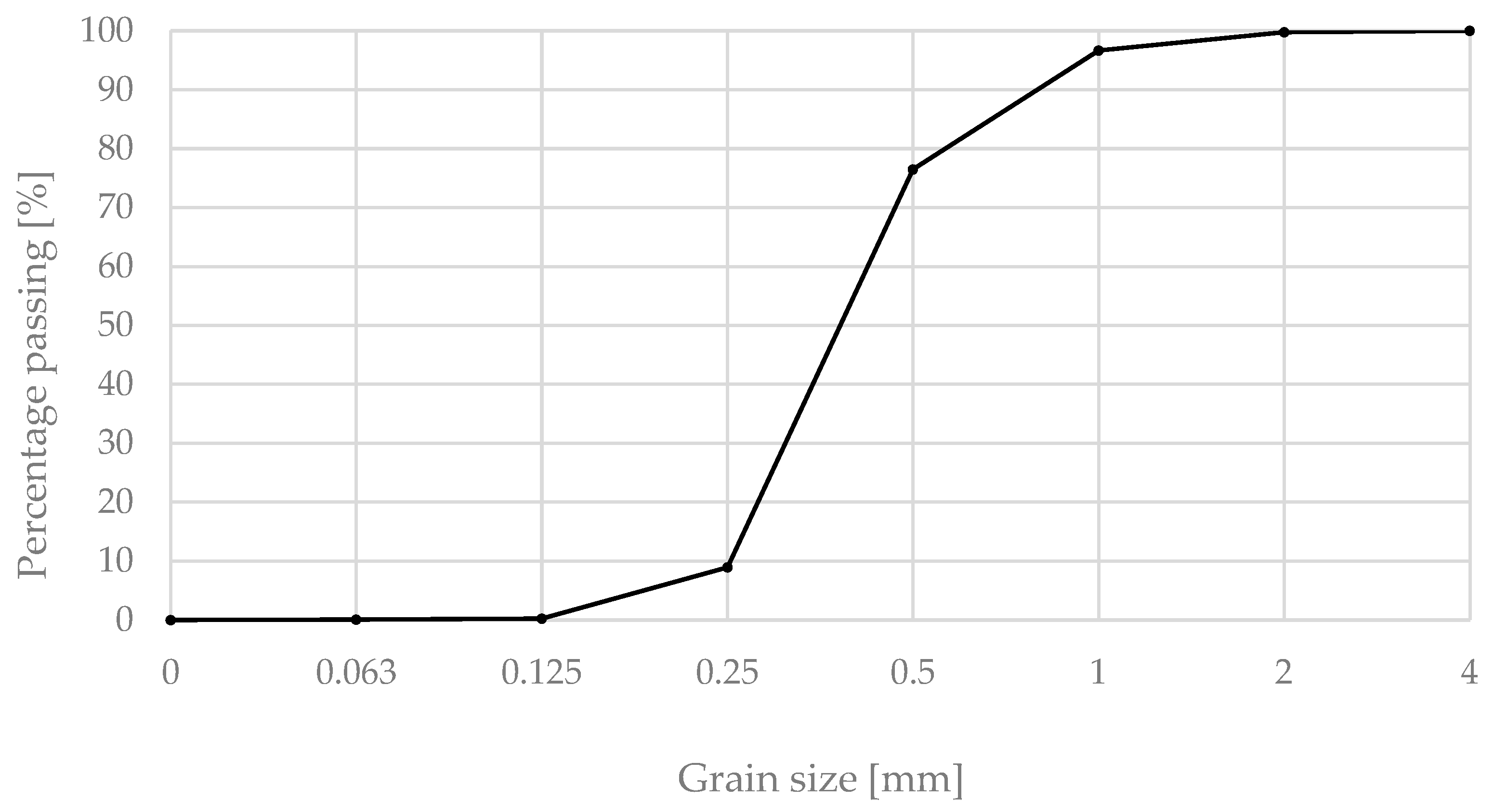
Vistula river sand 0/2 was used as a fine aggregate, with its properties confirmed according to various standards—PN-EN 933-1 (granulation) [24], PN-B-06714-46 (alkali-silica reaction) [25], and PN-EN 1744-1 (organic pollutants content) [26], among others. The water used in this study met the requirements of PN-EN 1008 [27]. The grain size distribution curve of the sand is presented in Figure 1.

Figure 1.
The grain size distribution of sand (0/2) used in the study.
A superplasticizer (aqueous polycarboxylate solution) was added to cement mortars to modify their rheological properties. It met the PN-EN 934-2 standard requirements [28] and was characterized by electrostatic and steric mechanisms of action.
The coarse aggregate used in the study was basalt aggregate of fraction 4/8, obtained by screening aggregate grains smaller than 4 mm from basalt aggregate fraction 2/8 from Gracze mine, Poland. It is also worth emphasizing that the basalt aggregate had a dark color, which facilitated digital image analysis of the external surface of the investigated composites, providing sufficient contrast between coarse aggregate grains and cement matrix.
Photocatalytic titanium dioxide P25 (Evonik, Shanghai, China), with properties detailed in Table 2, was used as the photocatalyst in this study. The phase composition and crystallite size were determined via X-ray diffraction (XRD, Bruker-AXS D8 DAVINCI, Billerica, MA, USA), and the specific surface area of the photocatalyst was measured using the BET method (ASAP 2020, Micromeritics, Norcross, GA, USA). For XRD analysis, samples were dried, placed in special steel holders, and properly smoothed. Afterward, the sample was placed in the measuring magazine and, straight after, in the diffractometer. The measurement was carried out in the range of 5–65° 2θ, with a single step of 0.02° 2θ lasting 5 s. Phase identification was performed by comparing the recorded diffractograms with reference patterns from the COD database using the DIFFRACplus EVA-SEARCH software (version 7). The sample for BET analysis was prepared under the following conditions: degassing at 200 °C (<0.1 Pa) for 4 h, with a temperature ramp rate of 10 °C/min. The BET range was set to 0.05 < p/p0 < 0.3, and 13 data points were selected for calculations.
Table 2.
Characteristics of photocatalyst (P25) used in the study.
CHRYSO Deco Lav N10 (CHRYSO, France) setting retarder was used to change the surface properties of prepared concrete samples.
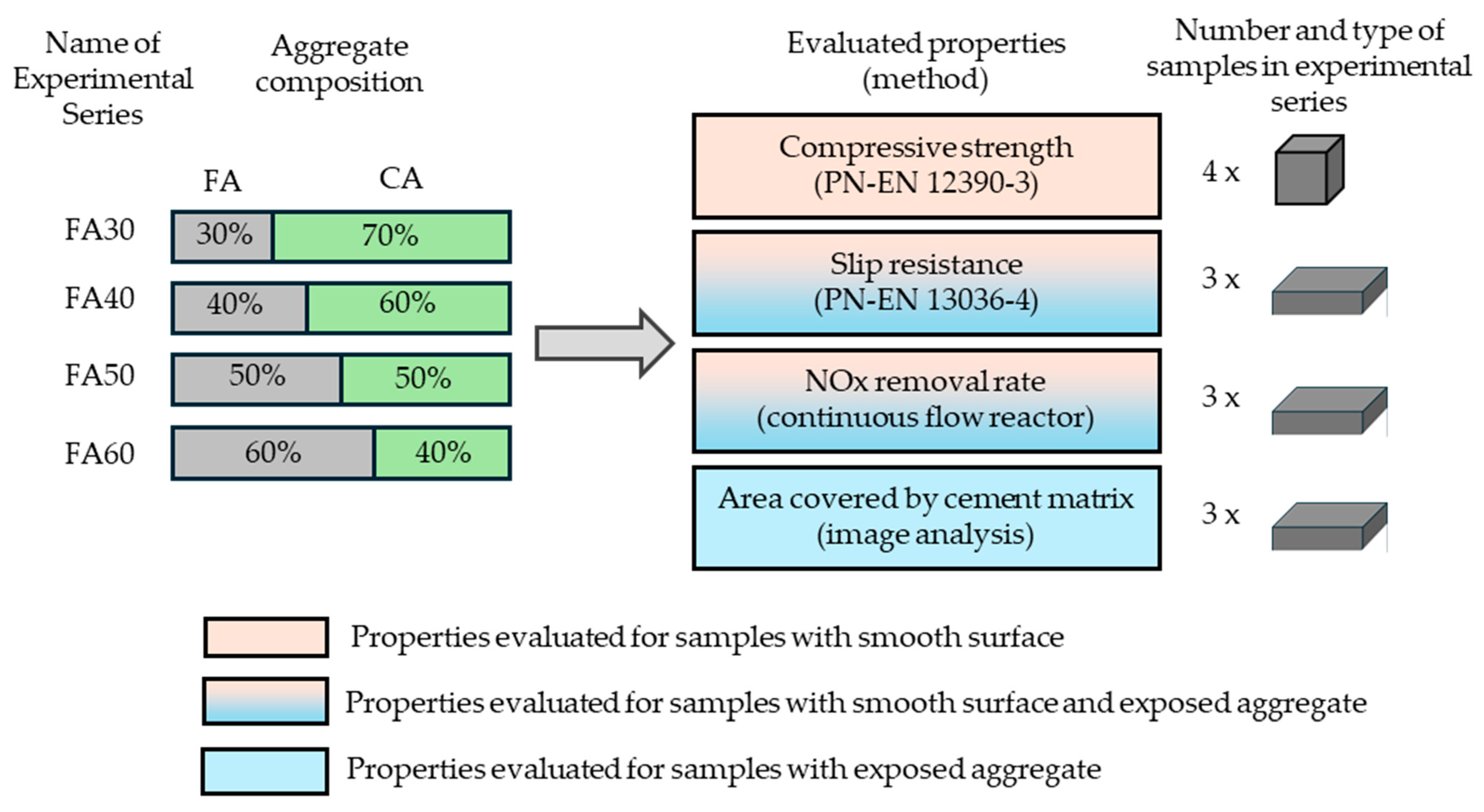
2.2. Experimental Framework
To introduce variability in the surface area of the exposed photocatalytic cement matrix on the concrete samples, the authors incorporated one variable related to the aggregate composition into the experiment—the fine aggregate content. The higher the fine aggregate content was, the less coarse aggregate was added to the concrete mix. As a result, after the application of the setting retarder, the surface area of the exposed cement matrix area increased. In total, eight photocatalytic concrete mixes were prepared—four with exposed aggregate and four reference series (Table 3). Apart from variations in fine aggregate content, all other ratios between the mix constituents, including the water-to-cement ratio, total aggregate content, and cement content, were kept constant. Additionally, the same amount of photocatalyst, 15 kg/m3, was used in each series. The photocatalyst was added in powder form during the mixing stage. The amount of superplasticizer varied between the series to achieve consistency class S1–S2 (according to PN-EN 12350-2 [29]), meeting the requirements for cement concrete used for road surfaces in Poland.
Table 3.
Compositions of concrete mixes per m3 used in the study (m.a.—mass of aggregate).
The surface of the samples after coarse aggregate exposure was evaluated in terms of slip resistance and the areas occupied by coarse aggregate and the cement matrix. By calculating the areas covered by these phases, a quantitative relationship was established between the NOx removal rate and the amount of cement matrix covering the external surface of the composite.
Slip resistance was measured for both reference and exposed aggregate surfaces as a simplified indicator of surface roughness, a parameter highlighted in the introduction as critical for optimizing air purification performance. Additionally, the compressive strength of samples from each composition was tested. While not directly related to air purification efficiency, this characteristic was assessed to ensure the concretes’ suitability for use as the upper layer of concrete pavements. It also served to evaluate whether porosity varied across the tested series, as mechanical properties are directly influenced by the porous structure of concrete. The research methodology is summarized in Figure 2.

Figure 2.
Experimental framework (acronyms: FA—fine aggregate; and CA—coarse aggregate).
2.3. Methods
To create samples with exposed aggregate, sides of the molds were first lined with tape, and the bottom was coated with a setting retarder. The retarder was applied in two thin layers and allowed to dry. After drying, the tape was removed, and an anti-adhesive agent was applied to those surfaces. Two types of molds were used: 140 × 160 × 40 mm for air purification efficiency and surface roughness tests, and 100 × 100 × 100 mm for compressive strength tests. Only half of the 140 × 160 × 40 mm samples were treated with the setting retarder, while the remaining ones served as reference samples in each series (samples without exposed coarse aggregate).
After preparing the concrete mix, the samples were molded and stored for 24 h in a curing chamber (temperature 20 ± 2 °C, and relative humidity RH ≥ 95%). After this period, the non-hydrated layer was washed off from 3 of the 6 samples measuring 140 × 160 × 40 mm in each series to expose the coarse aggregate. All samples were then returned to the curing chamber and cured for an additional 27 days before further testing.
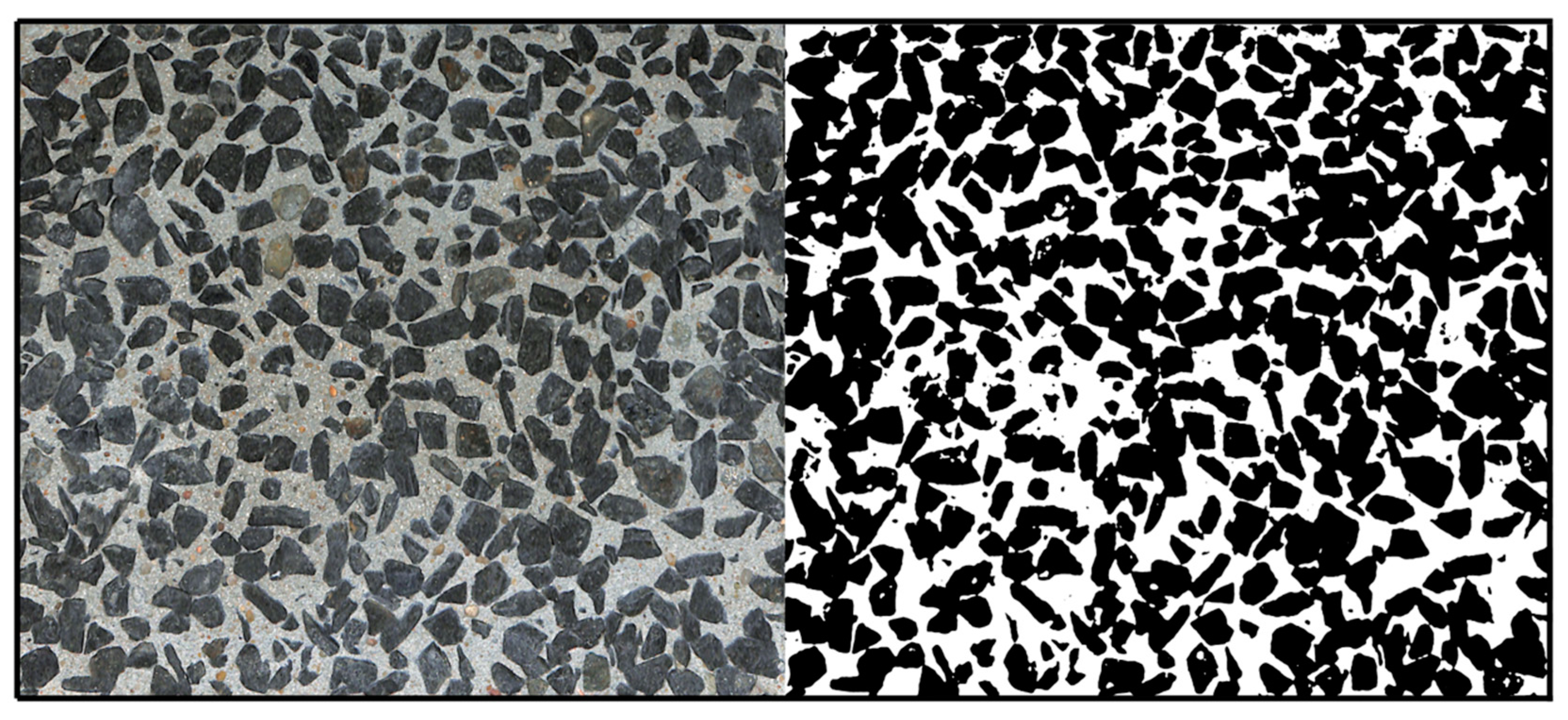
2.3.1. Digital Image Analysis—The Surface Area Occupied by Coarse Aggregate on Samples with Exposed Aggregate
Each sample was scanned using a ScanSnap SV600 (Ricoh Company, Kawasaki, Japan). All scans were processed using GIMP software (version 2.10.38) with the goal of obtaining a binary image. Binarization is a method used to convert color or monochrome images into binary images, typically achieved through thresholding. This image processing technique assigns a value of 0 to pixels brighter than the threshold value and a value of 255 to pixels darker than the threshold, depending on the threshold chosen (Figure 3). The image analysis determined the percentage of the area occupied by the photocatalytic cement matrix or coarse aggregate in samples with exposed aggregate.
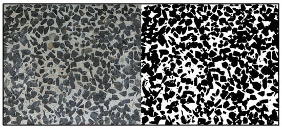
Figure 3.
The external surface with exposed coarse aggregate of a concrete sample FA50 before binarization (on the left side) of the image and after binarization (on the right side).
2.3.2. Air Purification Efficiency from NOx Pollutants
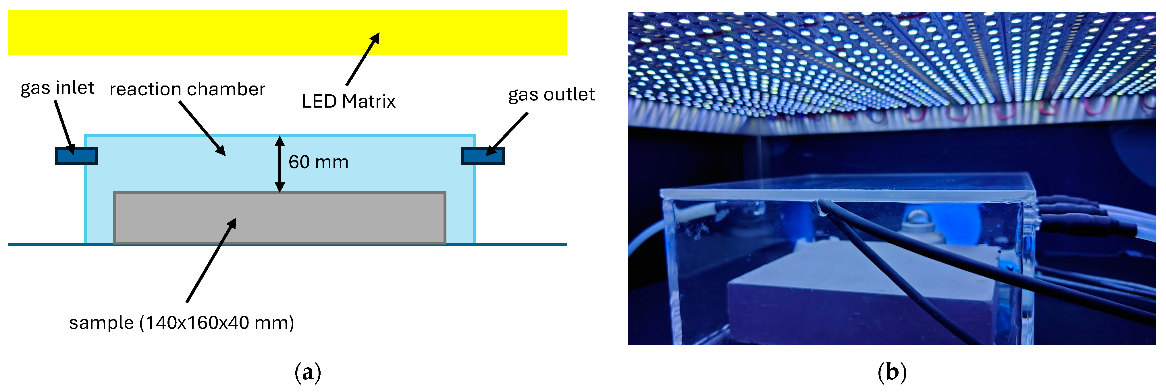
Air purification tests for nitrogen oxides were conducted following a procedure developed by the authors based on the ISO 22197-1 standard [30]. The tests were performed on 140 mm × 160 mm × 40 mm concrete samples, which underwent additional preparation before being placed in the testing apparatus. The photocatalytic surfaces were thoroughly cleaned of any external contaminants, including residual anti-adhesive agents and other impurities.
The first step involved sprinkling the test sample’s surface with distilled water and scrubbing it clean. The sample was then dried at 60 °C for two hours before being placed in the irradiation chamber for 16 h, with the test surface facing the light source. This was carried out to decompose organic impurities using UV-A radiation at an irradiance of 10 W/m2. In the final step, the photoactive surface was again cleaned with distilled water to remove any remaining impurities that had been burned off, followed by another drying cycle at 60 °C for two hours. The air purification efficiency against gaseous pollutants was tested no sooner than two hours after the last drying cycle. The samples prepared in this manner were then placed in a glass reaction chamber, with the investigated surface facing the light source (Figure 4).

Figure 4.
Experimental setup for the air purification efficiency test: (a) schematic diagram of the reaction chamber with the sample inside; and (b) photograph of the sample during the test.
UV-A LED strips (LuxaLight, Eindhoven, The Netherlands, 360 ± 5 nm, 14.4 W/m) were used as the UV-A light source, while Sun-Like™ TRI-R™ LED strips (Seoul Semiconductor, Ansan-si, Republic of Korea, 5000 K) served as the visible light source. The UV-A irradiation from the visible light source on the sample’s surface was 0.0 W/m2, with global irradiation set to 150 W/m2. The global irradiation of UV-A light was 1.0 W/m2. UV-A irradiance levels were measured using Delta Ohm pyranometer, covering the 315–400 nm range. The global irradiation was recorded using a Lambrecht METEO pyranometer, covering a wavelength range of 285–3000 nm.
During the experiment, the temperature inside the glass reaction chamber was maintained at 25 ± 3 °C, and the relative humidity was controlled at 40 ± 5%. The gas flow was kept constant at 2 L/min. Results (NO and NOx concentrations) were quantified using the Teledyne API T200 chemiluminescence detection analyzer (San Diego, CA, USA).
The test involved several steps to assess the photocatalytic properties of investigated concretes under three specific lighting conditions: UV-A light only, visible light only, and mixed conditions (both UV-A and visible light). The irradiance levels of both light sources were adjusted to simulate typical sunlight conditions observed in Poland during the autumn/winter season. The initial nitrogen oxide concentration of approximately 100 ppb was selected to represent average urban pollution levels. The detailed test procedure is outlined in Figure 5.
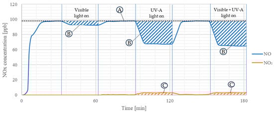
Figure 5.
A schematic of the test procedure for air purification from NOx in different irradiation conditions; A—constant flow of 2 L/min of approx. 100 ppb of NO in the reaction chamber; B—reduction in the concentration of NO due to specific irradiation (visible light, UV-A light, and combined visible and UV-A light; and C—generated NO2 due to photocatalytic reactions. Based on marked areas (blue and orange), the amount of both removed NO and generated NO2 per hour per m2 of photocatalytic surface was calculated.
The amount of NO introduced into the reactor, the amount of NO removed by the photocatalytic sample, and the NO2 produced during the photocatalytic process for each radiation cycle were then calculated. This enabled the characterization of each sample’s air purification potential, expressed as the absolute reduction of NOx in micrograms per hour per square meter of photocatalytic cement matrix (µg/h × 1/m2) under various irradiation conditions.
The test protocol developed by the authors differed from the ISO [19] standard for NO removal efficiency testing. Specifically, a reaction chamber with a greater gap between the specimen and the cover (60 mm versus 5 mm in ISO) was used, the NO concentration was reduced from 1 ppm to 0.1 ppm, and lower UV-A irradiation (1.0 W/m2 compared to ISO’s 10 W/m2) was applied. These modifications aimed to simulate urban environmental conditions where the photocatalytic composite might serve as a pavement material.
2.3.3. Slip Resistance and Compressive Strength
The slip resistance test was conducted in accordance with the PN-EN 13036-4 standard [31], using a slider mounted at the end of a pendulum arm. Before beginning the test, the pendulum was placed on a stable, flat surface to prevent any movement during testing. The apparatus was leveled using a vial and adjustment screws, and the pendulum arm was positioned vertically. The measurement indicator was aligned parallel to the pendulum arm, ensuring it did not touch the scale plate. Three control measurements were then performed to properly calibrate the apparatus.
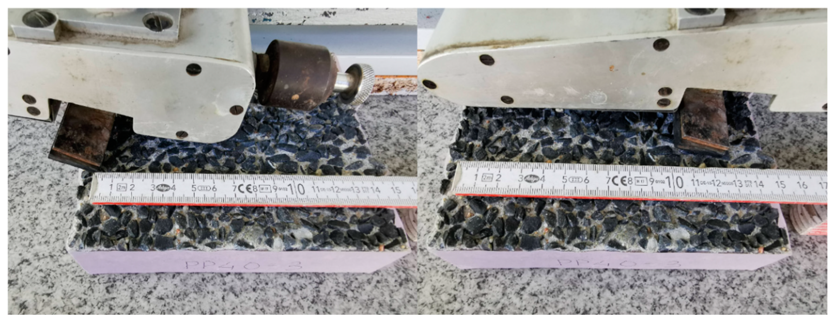
After setup, the test samples were placed on a flat surface beneath the pendulum arm. The height of the arm was adjusted for each sample so that the contact length between the rubber slider at the end of the pendulum and the test surface was between 12.5 and 12.7 cm (Figure 6).
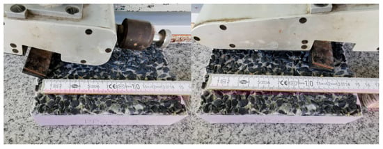
Figure 6.
A photograph of a sample with exposed coarse aggregate illustrating the procedure for adjusting the sliding path length for the pendulum test.
Once the height was set, the pendulum arm and measurement indicator were rotated counterclockwise until the pendulum arm was secured in the gripping block and the indicator rested on the gripping block arm. To begin the measurement, the pendulum arm was released and then caught on its return swing before the rubber slider touched the test surface again. The measurement was performed four times on the dry surface of the sample and then four times on the wet surface. If any result deviated significantly, the measurement was repeated until four consistent results were obtained. A total of eight measurements were conducted for each sample.
The test results were expressed as the Pendulum Test Value (PTV), which reflects the slip resistance of the surface. The higher the PTV (i.e., the greater the difference between the initial and final positions of the pendulum arm), the lower the risk of pedestrians slipping on the tested surface. Four slip potential ranges described by PTV could be highlighted: high (0–24 PTV), moderate (25–35 PTV), low (36+ PTV), and extremely low (75+ PTV) [20].
The compressive strength tests were carried out on 100 × 100 × 100 mm samples after 28 days of curing in accordance with the PN-EN 12390-3 standard [32]. The test was performed using an automatic testing machine, Controls Automax (Milano, Italy).
3. Results
3.1. Compressive Strength and Surface Area Covered with Cement Matrix
For all prepared concrete mixes, standard tests were conducted to evaluate the mechanical performance of the cementitious composites (Table 4). The mechanical properties were assessed for reference samples from each series (those without exposed aggregate on their external surface).
Table 4.
Compressive strength of prepared concrete mixes after 28 days of curing in the curing chamber.
The results showed that the 28-day compressive strength varied between the series, with a decreasing trend observed as the fine aggregate content increased, ranging from 50.1 MPa to 37.1 MPa. Based on the acceptance criteria in PN-EN 206 [33], the designed concretes could be classified into two compressive strength classes: C25/30 (FA60) and C30/37 (FA40, FA50, and FA30). According to Polish requirements for concrete pavements, a C30/37 concrete is suitable for use as the upper layer of concrete pavement but only for local roads with low to medium traffic volumes. The results also indicated that, as the volume of sand in the aggregate composition increased, the overall porosity of the concrete increased as well.
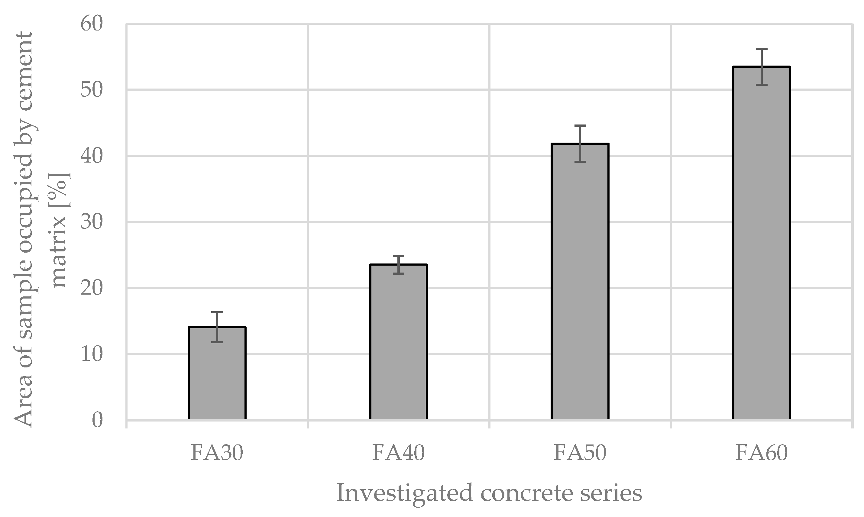
Depending on the concrete mix composition, the surface area occupied by the cement matrix varied (Figure 7). A quasi-linear increase in the cement matrix area was observed as the fine aggregate content in the mix increased. When the fine aggregate content rose from 30% to 60%, the cement matrix area increased significantly—from an average of 14.1% to 53.5% of the total sample surface area.
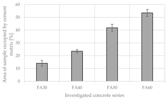
Figure 7.
The change in the surface area occupied by the cement matrix dependent on the initial content of fine aggregate in the concrete mix composition.
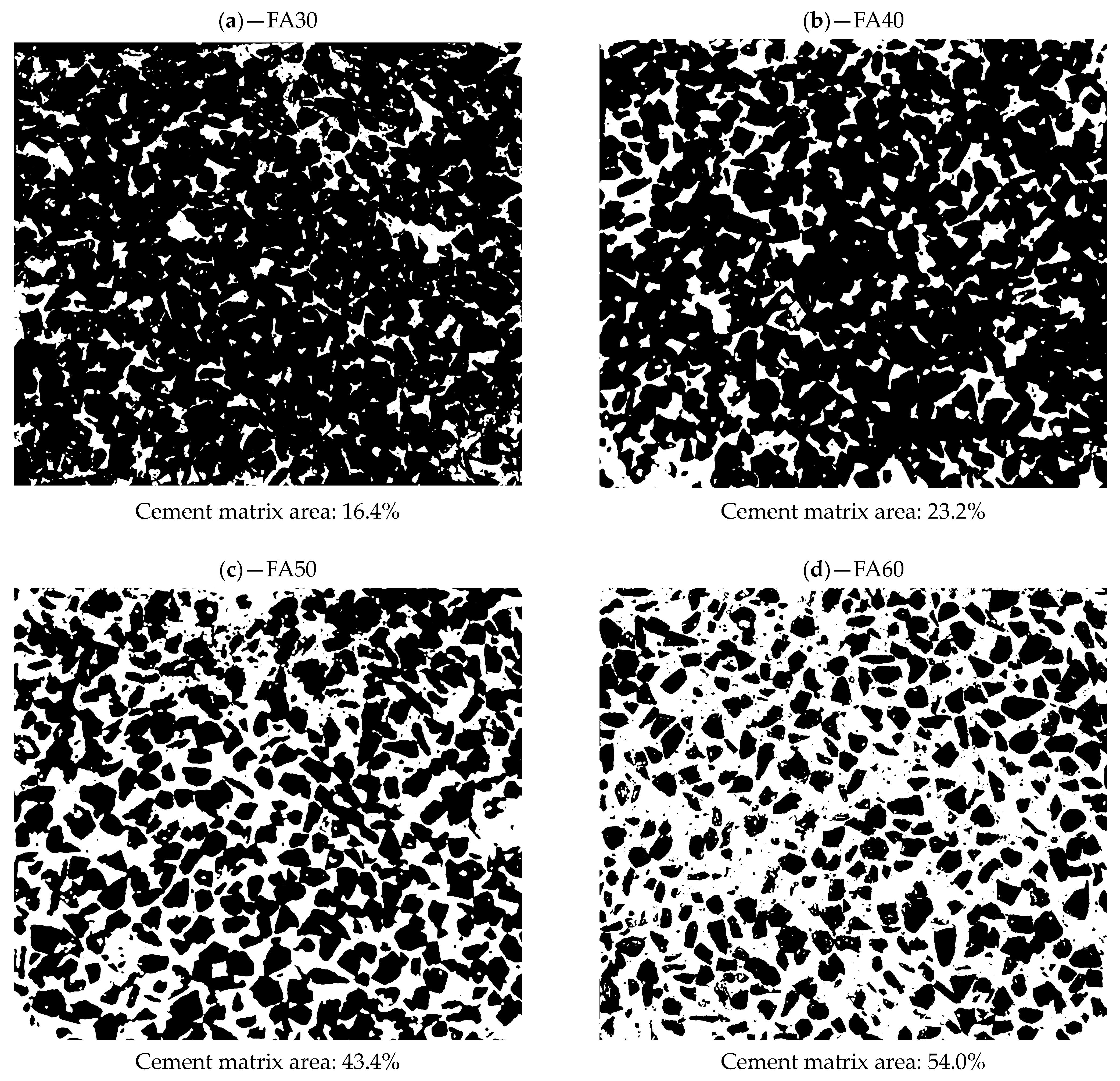
The change in the content of coarse aggregate did not influence its homogenous distribution within the volume of the mix—in all analyzed cases, the coarse aggregate was distributed evenly on the exposed surface of the composite (Figure 8), with the area it occupied dependent on the overall content of the coarse aggregate in the mix.
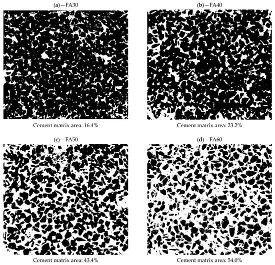
Figure 8.
Binarized scans of the external surface of samples with exposed coarse aggregate—the relative area of exposed cement matrix increased alongside the increase in the content of fine aggregate in the composition of concrete mixes: (a) FA30 (30% of fine aggregate); (b) FA40 (40% of fine aggregate); (c) FA50 (50% of fine aggregate); and (d) FA60 (60% of fine aggregate).
3.2. Slip Resistance
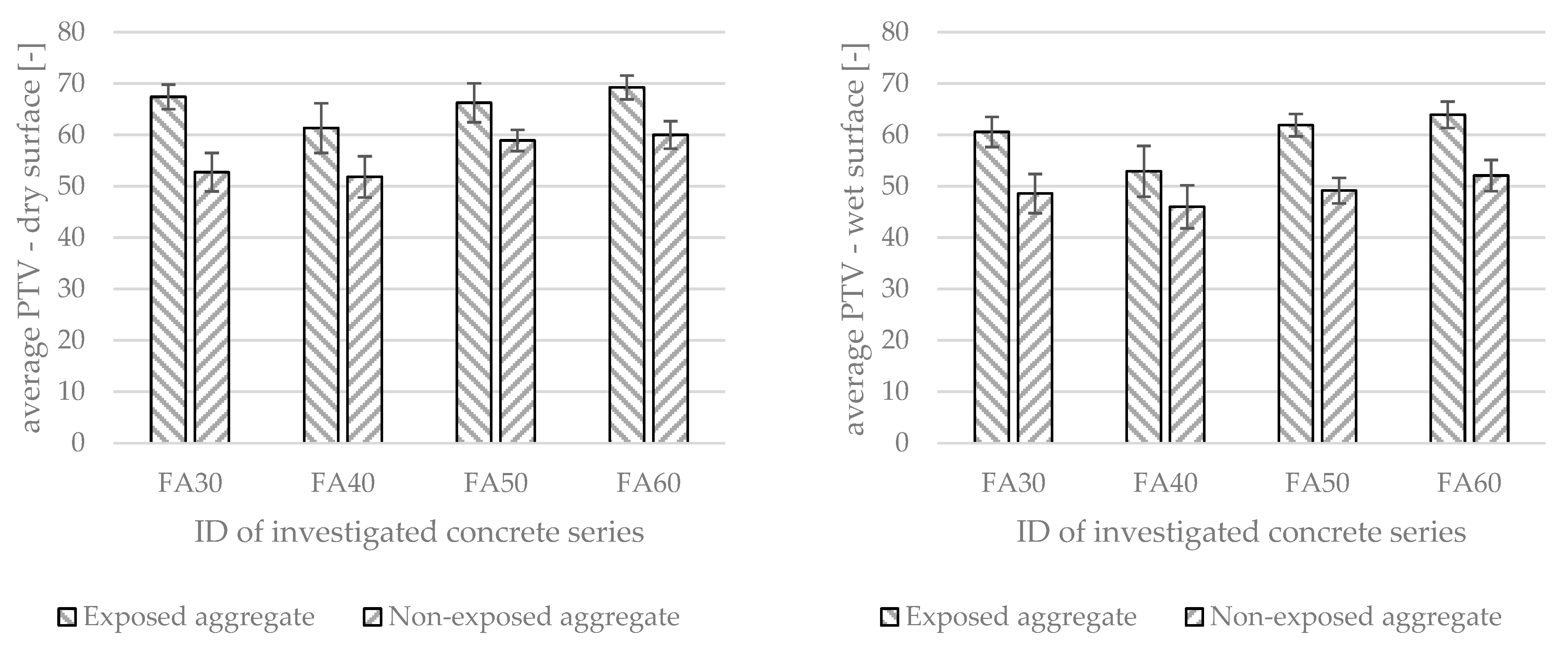
Exposing coarse aggregate on the surface contributed to an increase in the surface roughness of the analyzed samples. All investigated concrete series were characterized with a higher slip resistance in comparison with the reference series (with non-exposed coarse aggregate but of the same concrete mix composition)—Figure 9. All analyzed series, regardless of the additional surface modification, were characterized with a low slip potential—a PTV parameter with a higher value than 36.
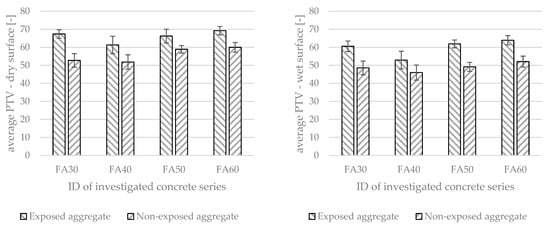
Figure 9.
The slip resistance of investigated surfaces (with exposed and non-exposed coarse aggregate) in both dry and wet conditions.
The change in the test conditions—wetting the external surface of samples—contributed to a deterioration in slip resistance; however, the reduction in PTV was not significant. The change in PTV obtained under different surface conditions was greater for series with exposed aggregate on their surface compared to reference series, approx. four to eight units lower than for tests conducted in dry conditions. In both conditions (dry and wet), all concrete series were characterized by a higher slip resistance than reference series.
Depending on the type of photocatalyst used, photocatalytic cementitious composites are usually characterized by hydrophilic surface properties that enhance their self-cleaning potential. In the case of the conducted research, although using photocatalytic nano-TiO2 that is characterized by hydrophilic properties, the photoactive surface of composites provided enough friction to be characterized with sufficient slip resistance, meeting the most rigorous requirements for pavement concrete.
3.3. Air Purification from NO
The change in concentration of both NO and NOx differed between the analyzed concrete series. All investigated reference concrete series (with non-exposed coarse aggregate) were characterized with a similar air purification efficiency (Figure 10), except for the FA30 series, the photocatalytic performance of which was approx. 30% lower (in the UV-a and combined light sources conditions) than the rest of the investigated reference series.

Figure 10.
Air purification efficiency of reference concrete series (with non-exposed aggregate).
Series with exposed coarse aggregate differed significantly in air purification properties. With the increase in the area of exposed coarse aggregate on the sample’s photocatalytic surface (the reduction in the area of photocatalytic cement matrix), the efficiency of NO removal decreased (Figure 11). This trend was most visible when carrying out the irradiation of concrete samples with UV-A and combined light sources (visible light and UV-A). All samples with exposed coarse aggregate, under all irradiation conditions, were characterized by a lower NO removal rate than in the case of appropriate reference series. As an example, reference series FA50, under UV-A light, was able to remove approx. 338 µg/hm2 of NO, while a series with the same composition but with an exposed aggregate in the same light conditions was able to remove approx. 162 µg/hm2 of NO. A similar dependency was observed for all of the analyzed concrete series.
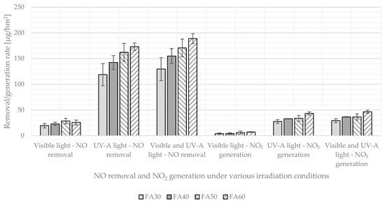
Figure 11.
Air purification efficiency of samples from investigated series with exposed coarse aggregate.
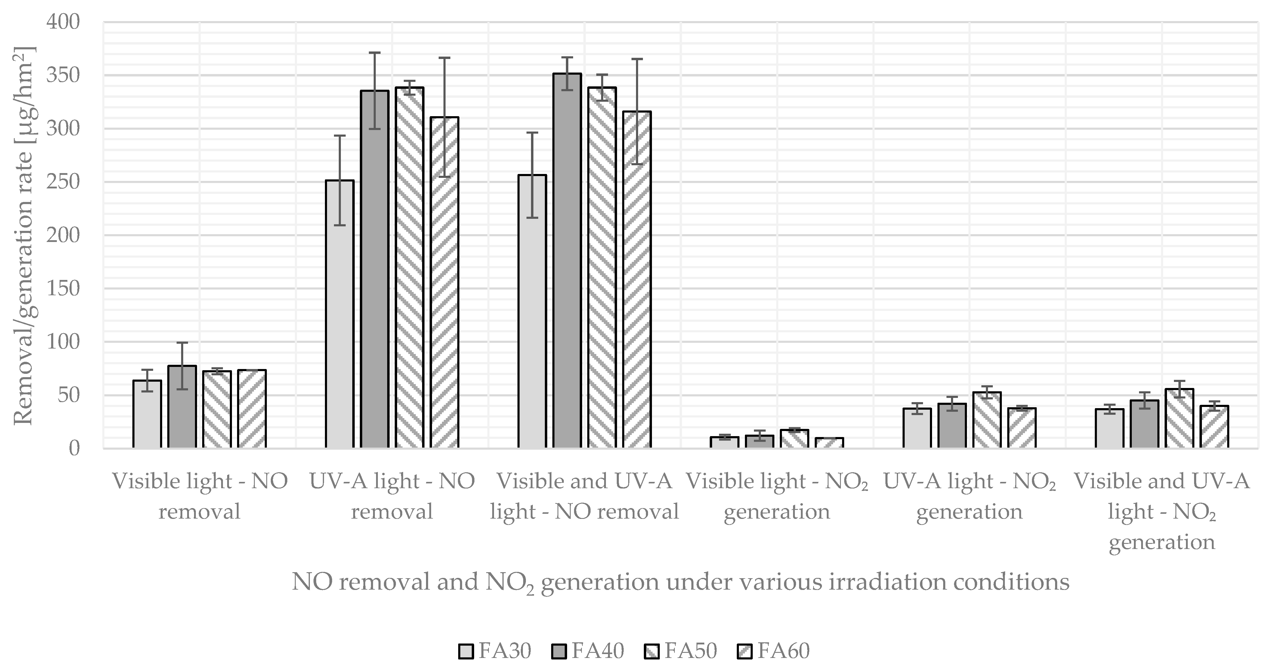
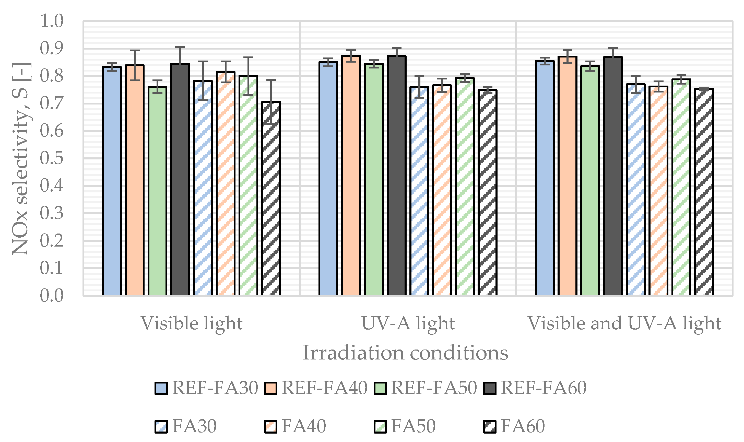
Based on performed tests, the NOx selectivity index of investigated photocatalytic surfaces during conducted tests was calculated according to Equation (3), linking the mass of the removed NO with the mass of the generated NO2 during the photocatalytic process in different light conditions (Figure 12).
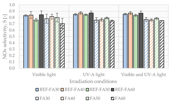
Figure 12.
NOx selectivity of investigated photocatalytic concretes in different irradiation conditions (reference series with non-exposed aggregate presented with full colors, and series with exposed coarse aggregate presented dashed with the color of the appropriate reference series).
In all investigated concrete series, the average selectivity of the photocatalytic process did not fall under 0.7—significantly more mass of NO was removed from the air than the generated NO2 in the process. The high selectivity observed with the first-generation photocatalyst (P25) could be attributed to the relatively low irradiation intensity of the UV-A light source used in this study. It is worth noting that all series with exposed aggregate were characterized by a lower selectivity (by approx. 10% compared to relevant reference series), especially in the case of UV-A and combined light conditions.
4. Discussion
The photocatalytic performance of cement composite modified by nano-TiO2 additives is dependent on multiple properties, both of the photocatalyst itself [34,35] and surface properties of the composite [36], as well as the external conditions in which photocatalytic reactions occur [37]. In the case of the conducted study, the authors decided to use a first-generation photocatalytic additive, active mostly in the UV part of the light spectrum and commonly used in the construction industry.
The removal rate of all analyzed concretes with exposed coarse aggregate was lower than in the case of reference series of the same composition. Usually, the cement matrix is considered to be the medium in which nanoparticulate photocatalytic materials are dispersed. Several different methods of its introduction into cementitious composites have been established over the years, including the use of microsphere carrier grains [38], aerogels [39], or coatings [17].
A trend was observed, linking the efficiency of the photocatalytic removal of NO with the area of the sample occupied by the photocatalytic cement matrix (Figure 13). The concrete series with the largest area of exposed coarse aggregate exhibited the lowest air purification potential. Conversely, as the exposed aggregate area decreased and the photocatalytic cement matrix area increased, the NO removal rates rose linearly. While the nano-TiO2 used in the study had minimal activity in the visible light spectrum, notable differences in photocatalytic performance for the analyzed concrete series were observed under UV-A and combined UV-A/visible light conditions.
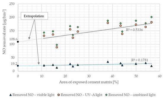
Figure 13.
The removal rate of NO in different light irradiation conditions dependent on the surface of the cement matrix on samples with different amounts of exposed coarse aggregate.
The efficiency of nitrogen oxide decomposition was selected as the dependent variable for regression analysis. Using the least-squares method, two linear regression equations were obtained, (4) and (5), corresponding to combined UV-A and visible light (4), and visible light alone (5), respectively.
where:
- —NO removal rate (combined light), µg/hm2;
- —NO removal rate (visible light), µg/hm2;
- AECM—area of exposed cement matrix on the surface of specimen, %.
The coefficient of determination, R2, was 0.54 for model (4) and 0.18 for model (5). The analysis of variance (ANOVA) for both equations indicated that the area occupied by the cement matrix did not significantly affect the air purification efficiency under visible light (Equation (5)), with p >> 0.05, while it had a significant effect (p << 0.05) under combined light. The moderate fit of model (4) to the experimental results suggested the presence of another unidentified variable significantly influencing the air purification efficiency. Additionally, the presence of a non-zero intercept in Equation (4) led to the hypothesis that exposed coarse aggregate grains might be covered with photocatalyst particles that were not washed away and remained adsorbed on their surface. Both of these hypotheses were set to be verified.
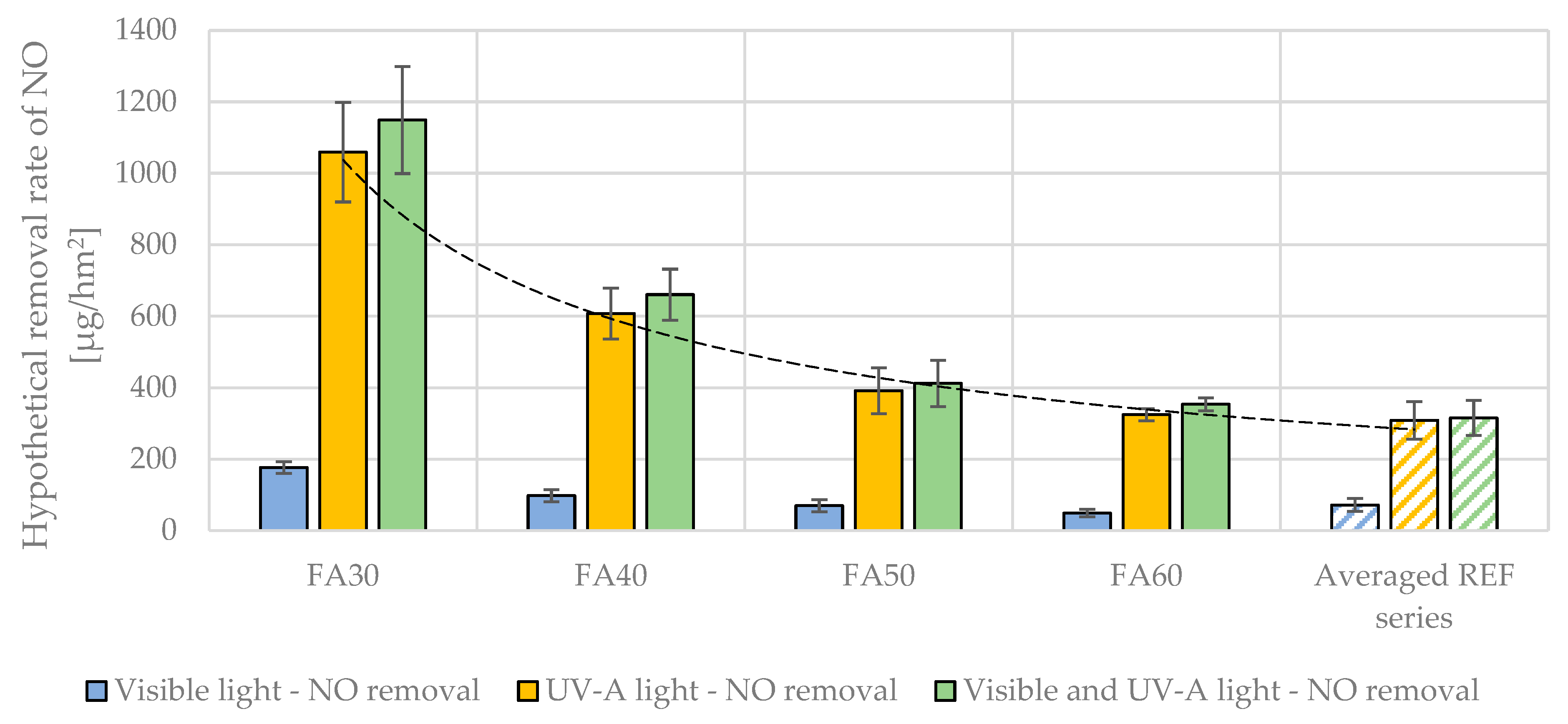
First, the hypothetical removal rate for concrete samples with exposed aggregate was calculated. These values were determined under the assumption that the sample was covered solely by the exposed cement matrix, without any exposed aggregate, and were compared to the average results obtained for reference samples. A steady increase in the calculated hypothetical performance of the exposed cement matrix was observed as the sand content in the analyzed concretes decreased (Figure 14), suggesting that both the area of the exposed cement matrix and its composition significantly influenced the air purification performance.
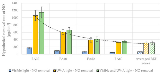
Figure 14.
Hypothetical NO removal rate of roughened cement matrix on samples with exposed coarse aggregate if cement matrix constituted the entire sample’s external surface compared with average values for all reference series.
In previous research by the authors [8], the influence of the cement mortar composition on photocatalytic performance was examined. The cement-to-sand ratio was identified as one of the most statistically significant factors among the investigated variables. In this study, successive concrete series were characterized by varying fine aggregate content while maintaining a consistent cement content across the series; as a result, the cement-to-fine aggregate ratio varied (from 0.72 for the FA30 series to 0.38 for the FA60 series). This variability may have contributed to changes in the photocatalytic performance of the exposed cement matrix. However, the extent of these changes, particularly in the FA30 and FA40 series, suggests an additional phenomenon affecting the composite’s photocatalytic properties, one not directly linked to the varying properties of the exposed cement matrix across different concrete series.
The external layer of cementitious composites typically exhibits distinct property differences compared to interior layers due to variations in the pore network characteristics [40,41]. These differences arise mainly from the surface’s exposure to environmental factors during binder hydration. Additionally, microcracking from shrinkage stresses can further increase the surface layer porosity. The increased capillary pore content directly impacts the composite’s durability [42,43], as pores provide pathways for aggressive agents like water, carbon dioxide, chloride ions, and sulfates, which can lead to deterioration.
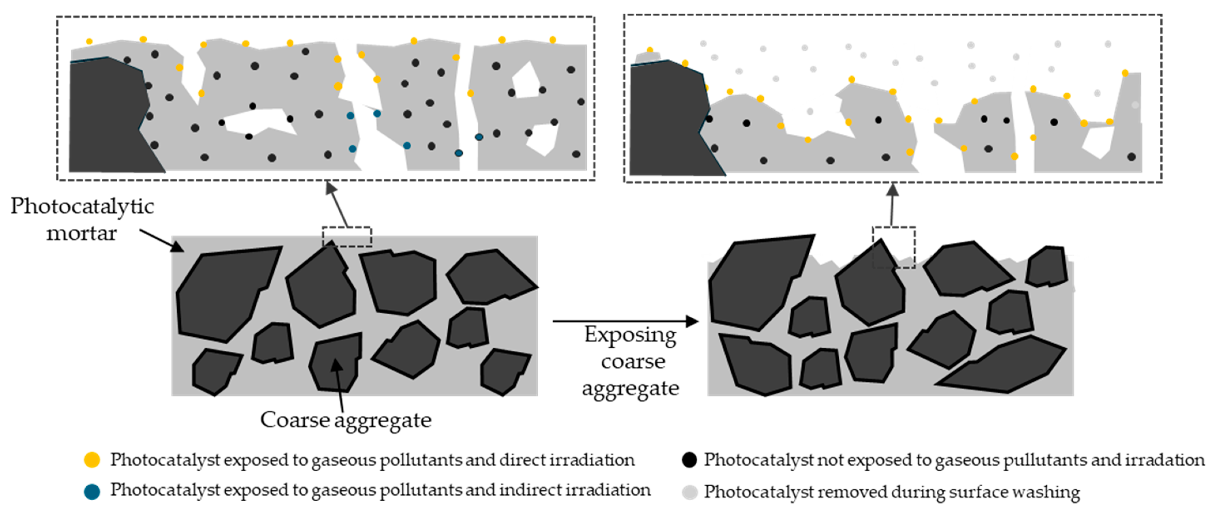
In photocatalytic composites, an increased near-surface porosity enhances the likelihood of contact between the photocatalyst and airborne pollutants while also expanding the photoactive area by allowing the external environment to access photocatalyst grains through the pore network. Removing this more porous external layer results in a dual effect on photocatalytic performance: a reduction due to the lower surface area for photocatalysis (since a higher-porosity layer is replaced by a lower-porosity one) and an increase from exposing more photocatalyst grains (as hydration products are removed from their surface). Previous studies have reported that nano-TiO2 can act as nucleation sites in cementitious composites [44,45]. Due to its nanoscale diameter, hydration products crystallize on the outer surface of the photocatalytic modifier, effectively limiting its exposure to the external environment. By applying a hydration retarder, a portion of these products can be washed away, exposing the modifier to external conditions and thereby increasing the photoactive surface area once the modifier grains are only partially covered with hydration products (Figure 15).

Figure 15.
Impact of coarse aggregate exposure on photocatalyst availability to gaseous pollutants and sun irradiation.
Assuming a homogeneous distribution of the photocatalyst within the composite and a consistent procedure for exposing the composite’s inner layer, any changes in photocatalytic performance should be comparable between samples, as the intensity of the surface modification remained consistent across series. In this modification, nano-TiO2 grains were uniformly dispersed within the cement paste, which coated both fine and coarse aggregates in the composite. As hydration advanced, an interlayer of hydration products adhered to the aggregate grains, forming a stable bond between the composite’s different phases. However, as the hydration retarder was applied and some non-hydrated cement paste was removed, the hydrated residuals and exposed nano-TiO2 grains became immobilized on the exposed coarse aggregate surface (see Figure 16). This effect contributed to an increase in the composite’s overall photoactive area beyond that of the exposed cement matrix.
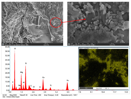
Figure 16.
SEM micrograph of basalt coarse aggregate grain removed from the external surface of a sample with exposed aggregate with EDS analysis showing Ti presence on the external surface of the grain.
Although nano-TiO2 grains were detected on the coarse aggregate surface, the air purification performance of samples with exposed aggregate remained lower than that of the reference samples. Additionally, the system exhibited a decreased selectivity in photocatalytic reactions, indicating that the contact time between pollutants and photocatalytic grains was reduced. This shift in reaction dynamics favored the photocatalytic production of nitrogen dioxide (NO2) over nitrate ions (NO3−). The aforementioned phenomena are closely linked to a reduction in near-surface porosity within the exposed cement matrix, which may influence the accessibility of active sites on the photocatalytic grains and subsequently alter the reaction pathways. The decrease in porosity could limit the adsorption and diffusion of pollutants [46], impacting the overall efficiency and selectivity of the photocatalytic process.
When the outer layer of the non-hydrated photocatalytic cement matrix was washed away, only a portion of the original TiO2 on the element’s external surface remained immobilized on the exposed coarse aggregate. Together, these two factors—a reduction in the photocatalytic cement matrix area and a lower TiO2 concentration on the exposed coarse aggregate than that in the washed-away cement matrix—contributed to the overall reduced photocatalytic efficiency in the modified concrete series. To counteract this effect, a well-established method of pre-soaking coarse aggregate in a TiO2 solution could be applied [47,48]. Using this technique would allow for a higher concentration of the photocatalytic modifier on the exposed aggregate surface compared to the modifier content in the cement matrix, thereby enhancing the photocatalytic performance of the cementitious composite.
5. Conclusions
The surface properties of photocatalytic cementitious composites have a statistically significant influence on the air purification performance of the composite. In the conducted research, a specific type of surface modification was investigated—the exposure of coarse aggregate with the use of a hydration retarder admixture applied on the photoactive surface of the composite during sample molding. Based on the laboratory results and their analysis, the following points were found:
- Exposed coarse aggregate can act as a carrier for photocatalytic nano modifiers, effectively immobilizing nanoparticles on its exposed external surface;
- The photocatalytic performance of cementitious composites is significantly impacted by the characteristics of the photoactive surface, including its roughness and exposure of photocatalyst grains to external conditions;
- Photocatalytic concretes with exposed coarse aggregate were characterized with a lower photocatalytic efficiency—this effect can be overcome through additional technological steps, which would increase the amount of TiO2 grains immobilized on the surface of the aggregate (soaking coarse aggregate in TiO2 solution prior to concrete mix preparation, etc.);
- Exposing the coarse aggregate contributed to an increase in the slip resistance of modified cementitious composites;
- A significant photocatalytic performance of cementitious composites modified by a first-generation photocatalyst (P25) was observed in the low UV-a irradiation conditions (1 W/m2), simulating the autumn/winter conditions in Central and Northern Europe.
Based on these findings, future designs of photocatalytic concrete composites could benefit from targeted surface modifications that balance nanoparticle immobilization, slip resistance, and environmental resilience. Optimizing the method of TiO2 application, such as through aggregate pre-treatment, could be a key focus, paving the way for high-efficiency photocatalytic surfaces that perform reliably across varied climates and lighting conditions.
Author Contributions
Conceptualization, K.C., M.K. and W.J.-R.; methodology, K.C., M.K. and W.J.-R.; software, K.C. and M.K.; validation, K.C. and M.K.; formal analysis, K.C., M.K. and W.J.-R.; investigation, K.C., M.K. and W.J.-R.; resources, K.C. and M.K.; data curation, K.C. and M.K.; writing—original draft preparation, M.K. and K.C.; writing—review and editing, K.C., M.K. and W.J.-R.; visualization, K.C. and M.K.; supervision, W.J.-R.; project administration, K.C. and M.K.; funding acquisition, K.C., M.K. and W.J.-R. All authors have read and agreed to the published version of the manuscript.
Funding
This research was funded under the research grant of the Warsaw University of Technology, supporting the scientific activity in the discipline of Civil Engineering, Geodesy, and Transport 2024.
Data Availability Statement
The data are included in the paper and available upon request.
Conflicts of Interest
The authors declare no conflicts of interest.
References
- Nazarenko, Y.; Pala, D.; Ariya, P.A. Air Quality Standards for the Concentration of Particulate Matter 2.5, Global Descriptive Analysis. Bull. World Health Organ. 2021, 99, 125–137D. [Google Scholar] [CrossRef]
- Al-Raqeb, H.; Ghaffar, S.H.; Al-Kheetan, M.J.; Chougan, M. Understanding the Challenges of Construction Demolition Waste Management Towards Circular Construction: Kuwait Stakeholder’s Perspective. Clean. Waste Syst. 2023, 4, 100075. [Google Scholar] [CrossRef]
- Ramacher, M.O.P.; Matthias, V.; Aulinger, A.; Quante, M.; Bieser, J.; Karl, M. Contributions of Traffic and Shipping Emissions to City-Scale NOx and PM2.5 Exposure in Hamburg. Atmos. Environ. 2020, 237, 117674. [Google Scholar] [CrossRef]
- EEA. Harm to Human Health from Air Pollution in Europe: Burden of Disease 2023. ETC HE Rep. 2023, 7, 104. [Google Scholar]
- Mata, T.M.; Martins, A.A.; Calheiros, C.S.; Villanueva, F.; Alonso-Cuevilla, N.P.; Gabriel, M.F.; Silva, G.V. Indoor Air Quality: A Review of Cleaning Technologies. Environments 2022, 9, 118. [Google Scholar] [CrossRef]
- Holnicki, P.; Kałuszko, A.; Nahorski, Z. A Projection of Environmental Impact of a Low Emission Zone Planned in Warsaw, Poland. Sustainability 2023, 15, 16260. [Google Scholar] [CrossRef]
- Chen, X.; Qiao, L.; Zhao, R.; Wu, J.; Gao, J.; Li, L.; Falletta, E. Recent Advances in Photocatalysis on Cement-Based Materials. J. Environ. Chem. Eng. 2023, 11, 109416. [Google Scholar] [CrossRef]
- Kalinowski, M.; Chilmon, K.; Jackiewicz-Rek, W.; Rakowski, B. The Influence of Selected Material Variables of Photocatalytic Cementitious Composites on the Self-Cleaning Properties and Air Purification Efficiency from NOx Pollutants. Sustainability 2023, 15, 853. [Google Scholar] [CrossRef]
- Li, C.; Wang, J.; Guo, H.; Ding, S. Low Temperature Synthesis of Polyaniline–Crystalline TiO2–Halloysite Composite Nanotubes with Enhanced Visible Light Photocatalytic Activity. J. Colloid Interface Sci. 2015, 458, 1–13. [Google Scholar] [CrossRef]
- Jędrzejczak, P.; Janczarek, M.; Parus, A.; Gapiński, B.; Hotěk, P.; Fiala, L.; Klapiszewski, Ł. Carbon-Modified TiO2 as a Promising and Efficient Admixture for Cementitious Composites: A Comprehensive Study of Photocatalytic, Mechanical and Structural Properties. J. Build. Eng. 2023, 78, 107747. [Google Scholar] [CrossRef]
- Zhao, A.; Yang, J.; Yang, E.H. Self-Cleaning Engineered Cementitious Composites. Cem. Concr. Compos. 2015, 64, 74–83. [Google Scholar] [CrossRef]
- Witkowski, H.; Jackiewicz-Rek, W.; Chilmon, K.; Jarosławski, J.; Tryfon-Bojarska, A.; Gąsiński, A. Air Purification Performance of Photocatalytic Concrete Paving Blocks after Seven Years of Service. Appl. Sci. 2019, 9, 1735. [Google Scholar] [CrossRef]
- Mishra, A.; Mehta, A.; Basu, S. Clay Supported TiO2 Nanoparticles for Photocatalytic Degradation of Environmental Pollutants: A Review. J. Environ. Chem. Eng. 2018, 6, 6088–6107. [Google Scholar] [CrossRef]
- Gang, L.; Wu, Y. Upcycling of waste concrete powder into a functionalized host for nano-TiO2 photocatalyst: Binding mechanism and enhanced photocatalytic efficiency. J. Clean. Prod. 2022, 366, 132918. [Google Scholar] [CrossRef]
- Witkowski, H.; Jarosławski, J.; Szkop, A.; Chilmon, K.; Kalinowski, M.; Jackiewicz-Rek, W. The Potential Risk of Nanoparticulate Release from Photocatalytic Pavement Concrete Surface Due to a Simulated Abrasion Load—An Experimental Study. Materials 2024, 17, 3022. [Google Scholar] [CrossRef] [PubMed]
- Boonen, E.; Beeldens, A. Recent Photocatalytic Applications for Air Purification in Belgium. Coatings 2014, 4, 553–573. [Google Scholar] [CrossRef]
- Guo, M.-Z.; Ling, T.-C.; Poon, C.S. Photocatalytic NOx degradation of concrete surface layers intermixed and spray-coated with nano-TiO2: Influence of experimental factors. Cem. Concr. Compos. 2017, 83, 279–289. [Google Scholar] [CrossRef]
- Wang, F.; Yang, L.; Wang, H.; Yu, H. Facile preparation of photocatalytic exposed aggregate concrete with highly efficient and stable catalytic performance. Chem. Eng. J. 2015, 264, 577–586. [Google Scholar] [CrossRef]
- Yang, Y.; Yan, Z.; Yang, S.; Tang, Z.; Li, W.; Yang, B.; Su, W.; Ji, T. Effect of substrate roughness on NOx removal of poly heptazine imides coated cement pastes exposed to washing and weathering. J. Clean. Prod. 2022, 377, 134397. [Google Scholar] [CrossRef]
- Zhang, J.; Tan, H.; Deng, X. NOx removal ability of photocatalytic cement-based materials with porous structure. J. Clean. Prod. 2022, 377, 134396. [Google Scholar] [CrossRef]
- PN-EN 197-1:2012; Cement Composition, Specifications and Conformity Criteria for Common Cements. PKN—The Polish Committee for Standardization: Warsaw, Poland, 2012.
- PN-EN 196-1:2016-07; Methods of Testing Cement—Part1: Determination of Strength. PKN—The Polish Committee for Standardization: Warsaw, Poland, 2016.
- PN-EN 196-3:2016; Methods of Testing Cement—Part 3: Determination of Setting Times and Soundness. PKN—The Polish Committee for Standardization: Warsaw, Poland, 2016.
- PN-EN 933-1:2012; Tests for Geometrical Properties of Aggregates—Part 1: Determination of Particle Size Distribution—Sieving Method. Polish Committee for Standardization: Warsaw, Poland, 2012.
- PN-B-06714-46; Mineral Aggregates—Tests—Determination of Potential Alkaline Reactivity Using the Rapid Method. Polish Committee for Standardization: Warsaw, Poland, 1992.
- PN-EN 1744-1+A1:2013; Tests for Chemical Properties of Aggregates—Part 1: Chemical Analysis. Polish Committee for Standardization: Warsaw, Poland, 2013.
- PN-EN 1008:2004; Mixing Water for Concrete—Specification for Sampling, Testing and Assessment of Suitability of Mixing Water for Concrete, Including Water Recovered from Concrete Production Processes. Polish Committee for Standardization: Warsaw, Poland, 2004.
- PN-EN 934-2+A1:2012; Admixtures for Concrete, Mortar and Cement Paste—Part 2: Admixtures for Concrete—Definitions, Requirements, Compliance, Marking and Labelling. Polish Committee for Standardization: Warsaw, Poland, 2012.
- PN-EN 12350-2:2019-07; Concrete Mix Testing—Part 2: Consistency Test Using the Slump Cone Method. PKN—The Polish Committee for Standardization: Warsaw, Poland, 2019.
- ISO 22197-1:2016; Fine Ceramics (advanced Ceramics, Advanced Technical Ceramics)—Test Method For Air-Purification Performance of Semiconducting Photocatalytic Materials. Part 1: Removal of nitric oxide. ISO (the International Organization for Standardization): Geneva, Switzerland, 2016.
- PN-EN 13036-4:2011; Method for Measurement of Slip/Skid Resistance of a Surface: The Pendulum Test. PKN—The Polish Committee for Standardization: Warsaw, Poland, 2011.
- PN-EN 12390-3:2019-07; Testing Hardened Concrete—Part 3: Compressive Strength of Test Specimens. PKN—The Polish Committee for Standardization: Warsaw, Poland, 2019.
- PN-EN 206+A2:2021; Concrete—Specification, performance, production and conformity. Polish Committee for Standardization: Warsaw, Poland, 2021.
- Haghighatmamaghani, A.; Haghighat, F.; Lee, C.S. Performance of Various Commercial TiO2 in Photocatalytic Degradation of a Mixture of Indoor Air Pollutants: Effect of Photocatalyst and Operating Parameters. Sci. Technol. Built Environ. 2019, 25, 600–614. [Google Scholar] [CrossRef]
- Zhang, Y.; Zhou, Y.; Dong, X.; Xi, X.; Dong, P. Recent advances in TiO2-based photocatalytic concrete: Synthesis strategies, structure characteristics, multifunctional applications, and CFD simulation. Chem. Eng. J. 2024, 496, 154186. [Google Scholar] [CrossRef]
- Kalinowski, M.; Woyciechowski, P.; Jackiewicz-Rek, W. Surface Modification of Photocatalytic Cementitious Composites with Polyacrylic Superabsorbent Polymers (SAP). Mater. Proc. 2023, 13, 23. [Google Scholar] [CrossRef]
- Sikkema, J.K.; Ong, S.K.; Alleman, J.E. Photocatalytic concrete pavements: Laboratory investigation of NO oxidation rate under varied environmental conditions. Constr. Build. Mater. 2015, 100, 305–314. [Google Scholar] [CrossRef]
- Szołdra, P.; Frąc, M.; Pichór, W. Photocatalytic degradation of nitrogen oxides (NOx) in a continuous-flow photoreactor with aluminosilicate microspheres coated with TiO2 thin films. Chem. Eng. Process. —Process Intensif. 2024, 202, 109856. [Google Scholar] [CrossRef]
- Liu, D.; Kaja, A.; Chen, Y.; Brouwers, H.J.H.; Yu, Q. Self-cleaning performance of photocatalytic cement mortar: Synergistic effects of hydration and carbonation. Cem. Concr. Res. 2022, 162, 107009. [Google Scholar] [CrossRef]
- Deysel, R.C.; Boshoff, W.P.; Smit, M.S. Implementing capillary pressure control measures to prevent plastic shrinkage cracking in concrete. Constr. Build. Mater. 2023, 397, 132407. [Google Scholar] [CrossRef]
- Nasir, M.; Alimi, W.O.; Oladapo, E.A.; Imran, M.; Kazmi, Z.A. Behavior of drying and plastic shrinkage of Portland cement concrete prepared and cured under harsh field. Dev. Built Environ. 2023, 16, 100252. [Google Scholar] [CrossRef]
- Jin, S.; Zhang, J.; Han, S. Fractal analysis of relation between strength and pore structure of hardened mortar. Constr. Build. Mater. 2017, 135, 1–7. [Google Scholar] [CrossRef]
- Ren, J.; Luo, X.; Bai, R.; Pan, C.; Zhang, J. Pore characteristics of different phase in nano-modified concrete and their influences on the compressive strength. J. Build. Eng. 2022, 46, 103784. [Google Scholar] [CrossRef]
- Li, Z.; Wang, J.L.; Li, Y.; Yu, X.; Han, B.G. Investigating size effect of anatase phase nano-TiO2 on the property of cement-based composites. Mater. Res. Express. 2018, 5, 085034. [Google Scholar] [CrossRef]
- Choi, Y.-C. Impact of TiO2 powder type on hydration and photocatalytic NOx degradation in cement paste. Results Eng. 2024, 24, 103187. [Google Scholar] [CrossRef]
- Kalinowski, M.; Chilmon, K.; Bogacki, J.; Woyciechowski, P. Organic and Inorganic Modifications to Increase the Efficiency in Immobilization of Heavy Metal (Zn) in Cementitious Composites—The Impact of Cement Matrix Pore Network Characteristics. Materials 2024, 17, 5281. [Google Scholar] [CrossRef] [PubMed]
- Yang, Z.; Xu, Y.; Cai, X.; Wu, J.; Wang, J. Studying properties of pervious concrete containing recycled aggregate loaded with TiO2/LDHs and its liquid pollutant purification. Constr. Build. Mater. 2023, 406, 133398. [Google Scholar] [CrossRef]
- Chen, X.-F.; Jiao, C.-J. A photocatalytic mortar prepared by tourmaline and TiO2 treated recycled aggregates and its air-purifying performance. Case Stud. Constr. Mater. 2022, 16, e01073. [Google Scholar] [CrossRef]


Disclaimer/Publisher’s Note: The statements, opinions and data contained in all publications are solely those of the individual author(s) and contributor(s) and not of MDPI and/or the editor(s). MDPI and/or the editor(s) disclaim responsibility for any injury to people or property resulting from any ideas, methods, instructions or products referred to in the content. |
© 2024 by the authors. Licensee MDPI, Basel, Switzerland. This article is an open access article distributed under the terms and conditions of the Creative Commons Attribution (CC BY) license (https://creativecommons.org/licenses/by/4.0/).