
Vibration Measurement and Numerical Simulation of the Effect of Non-Structural Elements on Dynamic Properties of Large-Span Structures
Abstract
1. Introduction
2. Description of Test Structures
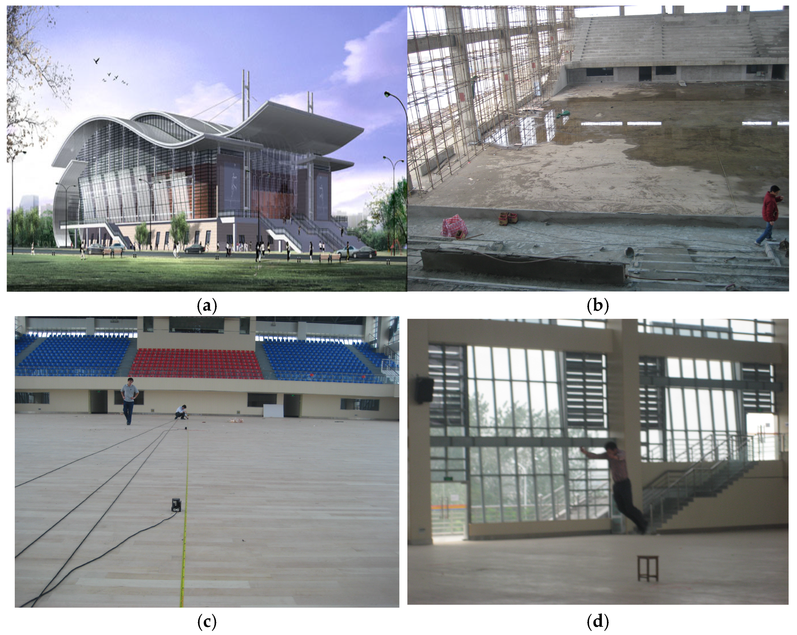
2.1. BU Stadium
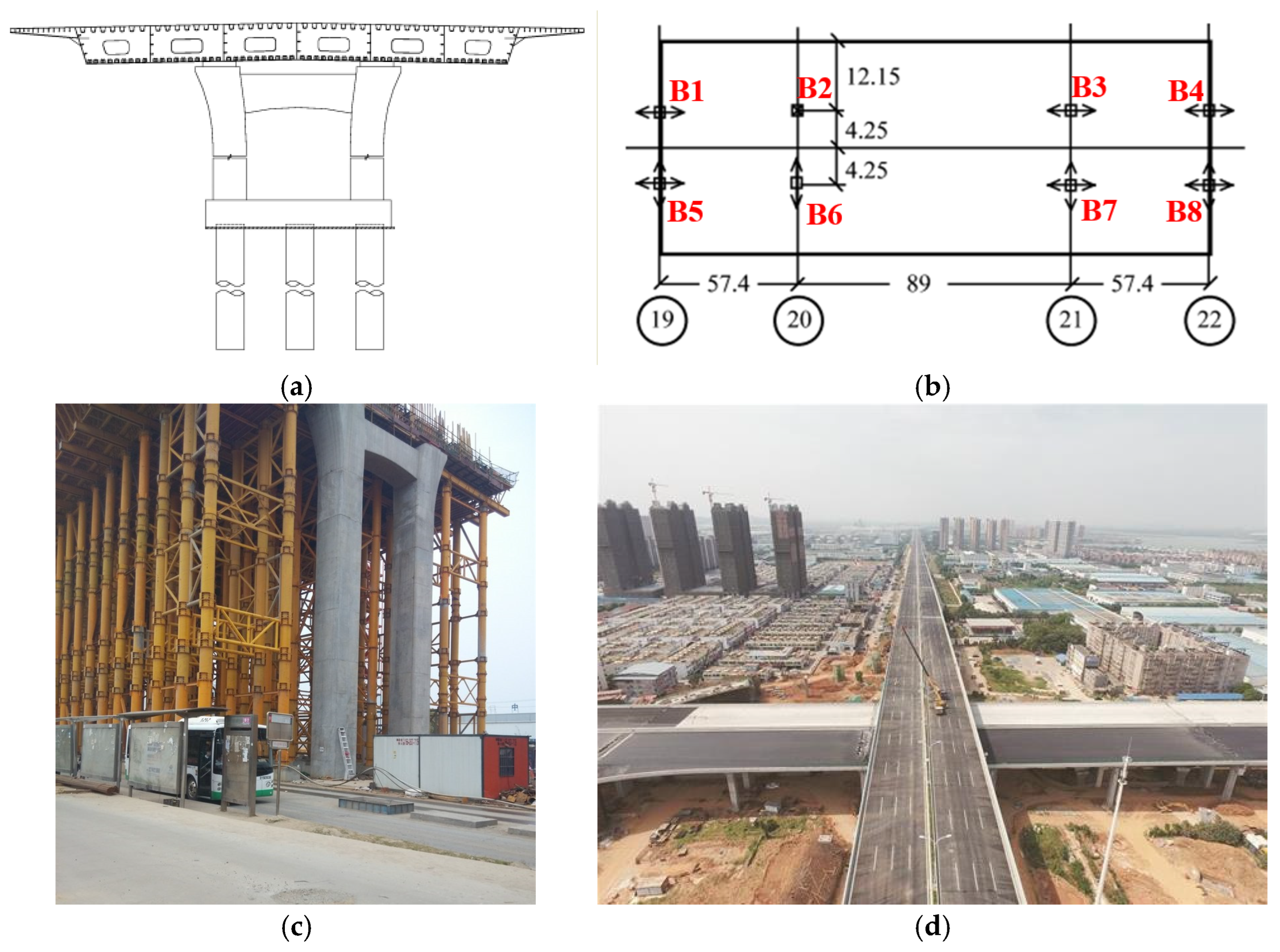
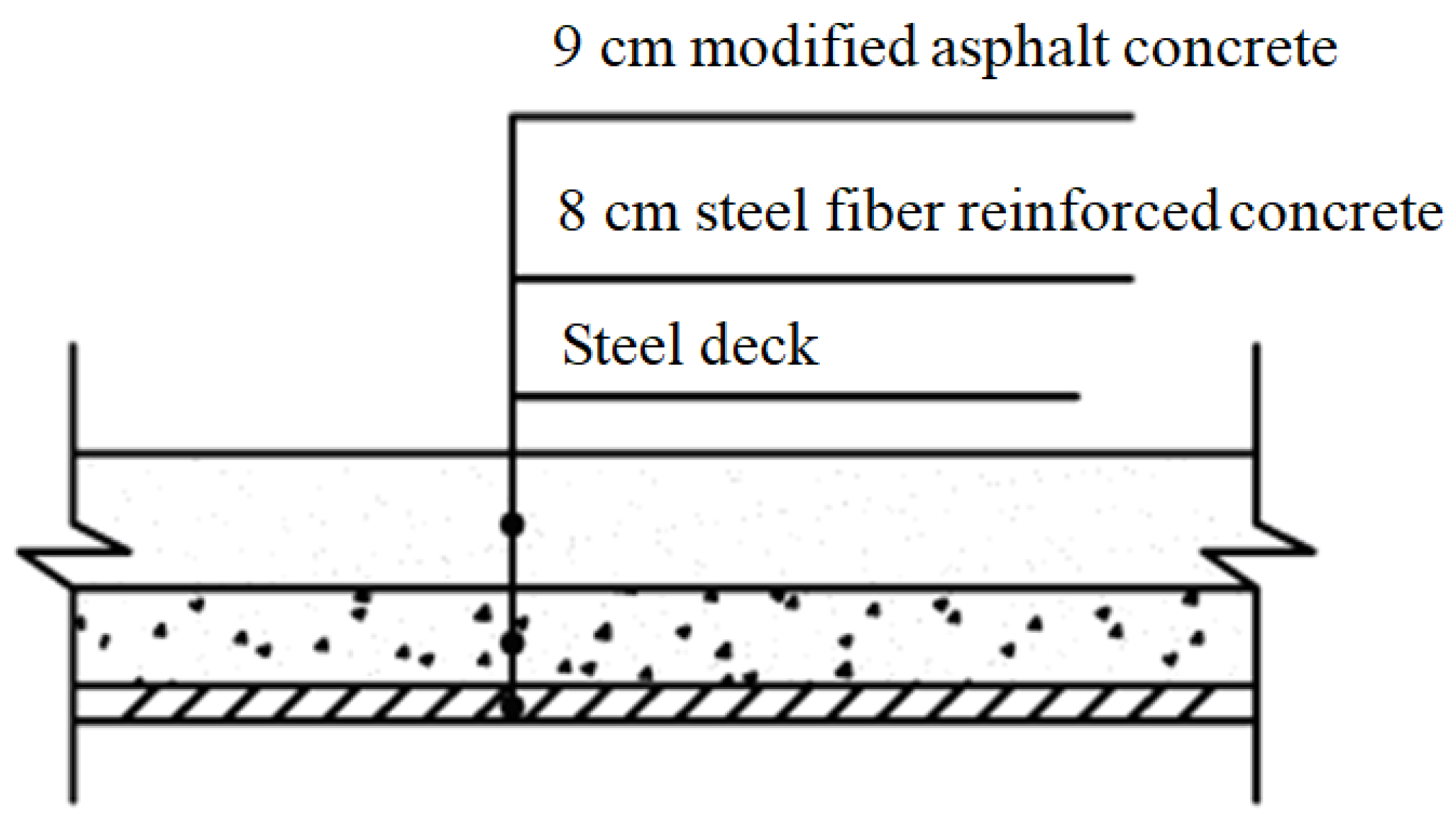
2.2. Dongfeng Bridge
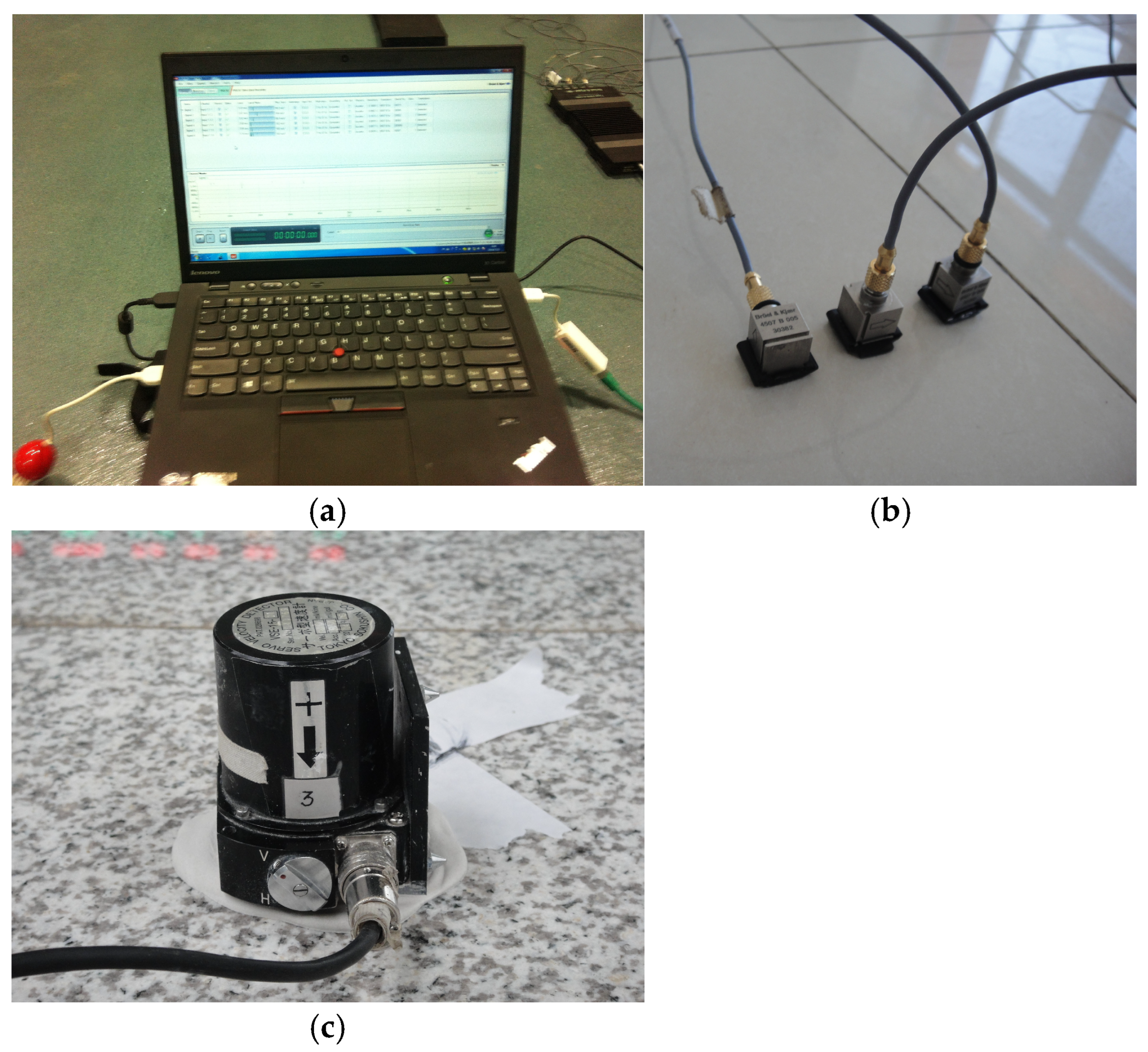
3. Modal Testing and Parameter Identification of Test Structures Under Different Construction Phases
3.1. Modal Testing of BU Stadium
3.2. Modal Testing of Dongfeng Bridge
4. Modeling of Non-Structural Elements
4.1. Main Types of NSEs in Large-Span Structures
4.2. Basic Principle and Modeling Methods of NSEs
5. Validation of the Proposed Method
5.1. BU Stadium
5.2. Dongfeng Bridge
6. Conclusions
Author Contributions
Funding
Data Availability Statement
Conflicts of Interest
References
- Devin, A.; Fanning, P.J. Non-structural elements and the dynamic response of buildings: A review. Eng. Struct. 2019, 187, 242–250. [Google Scholar] [CrossRef]
- Cavaleri, L.; Papia, M.; Macaluso, G.; Di Trapani, F.; Colajanni, P. Definition of diagonal Poisson’s ratio and elastic modulus for infill masonry walls. Mater. Struct. 2014, 47, 239–262. [Google Scholar] [CrossRef]
- Klingner, R.E.; Bertero, V.V. Earthquake resistance of infilled frames. J. Struct. Eng. ASCE 1978, 104, 973–989. [Google Scholar] [CrossRef]
- Chrysostomou, C.Z.; Asteris, P.G. On the in-plane properties and capacities of infilled frames. Eng. Struct. 2012, 41, 385–405. [Google Scholar] [CrossRef]
- Telue, Y.; Mahendran, M. Behavior and design of cold formed steel wall frames lined with plasterboard on both sides. Eng. Struct. 2004, 26, 567–579. [Google Scholar] [CrossRef]
- Telue, Y.; Mahendran, M. Behavior of cold-formed steel wall frames lined with plasterboard. J. Constr. Steel Res. 2001, 57, 435–452. [Google Scholar] [CrossRef]
- Gaiotti, R.; Smith, B. Stiffening of moment resisting frame by precast concrete cladding. PCI J. 1992, 37, 80–92. [Google Scholar] [CrossRef]
- Madan, A.; Reinhorn, A.M.; Mander, J.B.; Valles, R.E. Modeling of masonry infill panels for structural analysis. J. Struct. Eng. 1997, 123, 1295–1302. [Google Scholar] [CrossRef]
- Saifullah, I.; Gad, E.; Shahi, R.; Wilson, J.; Lam, N.; Watson, K. Behavior of plasterboard-lined steel-framed ceiling diaphragms. Thin-Walled Struct. 2019, 141, 1–14. [Google Scholar] [CrossRef]
- Brandolese, S.; Fiorin, L.; Scotta, R. Seismic demand and capacity assessment of suspended ceiling systems. Eng. Struct. 2019, 193, 219–237. [Google Scholar] [CrossRef]
- Reynolds, P. The effects of raised access flooring on the vibrational performance of long-span concrete floors. Ph.D. Dissertation, University of Sheffield, Sheffield, UK, 2000. [Google Scholar]
- Miskovic, Z.; Pavic, A.; Reynolds, P. Effects of full-height nonstructural partitions on modal properties of two nominally identical building floors. Can. J. Civ. Eng. 2009, 36, 1121–1132. [Google Scholar] [CrossRef]
- Su, R.K.L.; Chandler, A.M.; Sheikh, M.N.; Lam, N.T.K. Influence of non-structural components on lateral stiffness of tall buildings. Struct. Des. Tall Spec. Build. 2005, 14, 143–164. [Google Scholar] [CrossRef]
- Petrovic, S.; Pavic, A. Effects of non-structural partitions on vibration performance of floor structures: A literature Review. In Proceedings of the International Conference on Structural Dynamics (EURODYN 2011), Leuven, Belguim, 4–6 July 2011. [Google Scholar]
- Devin, A.; Fanning, P.J. The evolving dynamic response of a four storey reinforced concrete structure during construction. Shock Vib. 2012, 19, 1051–1059. [Google Scholar] [CrossRef]
- Falati, S. The Contribution of Non-Structural Components to the Overall Dynamic Behaviour of Concrete Floor Slabs. Ph.D. Thesis, New College, Oxford, UK, 1999. [Google Scholar]
- Li, B.; Hutchinson, G.L.; Duffield, C.F. The influence of non-structural components on tall building stiffness. Struct. Des. Tall Spec. Build. 2011, 20, 853–870. [Google Scholar] [CrossRef]
- Craig, J.; Leistikow, R.; Fennell, C. Experimental studies of the performance of precast cladding connections. In Proceedings of the Ninth World Conference on Earthquake Engineering, Tokyo, Japan, 2–9 August 1988; pp. 201–206. [Google Scholar]
- Devin, A.; Fanning, P.J.; Middleton, C.J.; Pavic, A. Structural dynamic parameter identification and the effect of test techniques. In Topics in Dynamics of Civil Structures, Volume 4: Proceedings of the 31st IMAC, A Conference on Structural Dynamics; Springer: New York, NY, USA, 2013; Volume 2013, pp. 171–181. [Google Scholar]
- Wyatt, T.A. Design Guide on the Vibration of Floors; Steel Construction Institute: London, UK, 1989. [Google Scholar]
- Kim, Y.M.; You, K.P. Dynamic responses of a tapered tall building to wind loads. J. Wind Eng. Ind. Aerodyn. 2002, 90, 1771–1782. [Google Scholar] [CrossRef]
- Devin, A.; Fanning, P.J. Impact of nonstructural components on modal response and structural damping. Top. Dyn. Civ. Struct. 2012, 1, 415–421. [Google Scholar]
- Jiménez-Alonso, J.F.; Pérez-Aracil, J.; Hernández Díaz, A.M.; Sáez, A. Effect of Vinyl Flooring on the Modal Properties of a Steel Footbridge. Appl. Sci. 2019, 9, 1374. [Google Scholar] [CrossRef]
- He, W.; Xie, W. Characterization of stationary and walking people on vertical dynamic properties of a lively lightweight bridge. Struct. Control Health Monit. 2018, 25, e2123. [Google Scholar] [CrossRef]
- Pavic, A.; Miskovic, Z.; Reynolds, P. Modal Testing and Finite Element model updating of a lively open-plan composite building floor. J. Struct. Eng. 2007, 133, 550–558. [Google Scholar] [CrossRef]
- Ewins, D.J. Modal Testing: Theory and Practice, 2nd ed.; Research Studies Press Ltd.: Baldock, Hertfordshire, UK, 2000. [Google Scholar]
- Zou, C.; Li, X.; He, C.; Zhou, S. An efficient method for estimating building dynamic response due to train operations in tunnel considering transmission path from source to receiver. Comput. Struct. 2024, 305, 107555. [Google Scholar] [CrossRef]
- He, W.; Liu, J.; Song, S.; Liu, P. A non-contact vehicle weighing approach based on bridge weigh-in-motion framework and computer vision techniques. Measurement 2024, 225, 113994. [Google Scholar] [CrossRef]
- Qiu, Y.; Zou, C.; Hu, J.; Chen, J. Prediction and mitigation of building vibrations caused by train operations on concrete floors. Appl. Acoust. 2024, 219, 109941. [Google Scholar] [CrossRef]
- Li, X.; Chen, Y.; Zou, C.; Chen, Y. Train-induced vibration mitigation based on foundation improvement. J. Build. Eng. 2023, 76, 107106. [Google Scholar] [CrossRef]
- He, W.; He, K.; Cui, H.; Wang, G. Using a rhythmic human shaker to identify modal properties of a stationary human body on a footbridge. J. Sound Vib. 2022, 540, 117309. [Google Scholar] [CrossRef]
- He, W.; Cui, H.; Yang, S. Estimation of structural dynamic response induced by individual sit-to-stand loading using acceleration response spectrum approach. Mech. Syst. Signal Process. 2024, 211, 111233. [Google Scholar] [CrossRef]
- Peeters, B.; De Roeck, G. Reference-based stochastic subspace identification for output-only modal analysis. Mech. Syst. Signal Process. 1999, 13, 855–878. [Google Scholar] [CrossRef]
- Reynders, E.; De Roeck, G. Reference-based combined deterministic-stochastic subspace identification for experimental and operational modal analysis. Mech. Syst. Signal Process. 2008, 22, 617–637. [Google Scholar] [CrossRef]
- Zivanovic, S.; Pavic, A.; Reynolds, P. Vibration serviceability of footbridges under human-induced excitation: A literature review. J. Sound Vib. 2005, 279, 1–74. [Google Scholar] [CrossRef]
- Zhang, C. Research on Modal Parameters Identification and Riding Comfort of the Elevated Bridge. Master’s Thesis, Wuhan University of Technology, Wuhan, China, 2016. (In Chinese). [Google Scholar]
- Minette, R.S.; SilvaNeto, S.F.; Vaz, L.A. Experimental modal analysis of electrical submersible pumps. Ocean Eng. 2016, 124, 168–179. [Google Scholar] [CrossRef]
- Avic, O. Amplitude-dependent damping in vibration serviceability: Case of a laboratory footbridge. J. Archit. Eng. 2016, 22, 04016005. [Google Scholar]
- Mazza, F. In-plane-out-of-plane non-linear model of masonry infills in the seismic analysis of r.c.-framed buildings. Earthq. Eng. Struct. Dyn. 2019, 48, 432–453. [Google Scholar] [CrossRef]
- Di Nino, S.; Luongo, A. A simple homogenized orthotropic model for in-plane analysis of regular masonry walls. Int. J. Solids Struct. 2019, 167, 156–169. [Google Scholar] [CrossRef]
- Aras, F. Laboratory tests and vibration surveys for the mechanical properties of infill walls. J. Perform. Constr. Facil. 2018, 32, 04017117. [Google Scholar] [CrossRef]
- Shankar, S.; Harmesh, K. Structural Dynamic Model Updating Techniques: A State of the Art Review. Arch. Comput. Methods Eng. 2016, 23, 515–533. [Google Scholar]
- Ren, W.X.; Jaishi, B. Use of modal flexibility and normalized modal difference for vibration mode shape expansion. In Proceedings of the 2nd International Conference on Structural Condition Assessment, Monitoring and Improvement (SCAMI-2), Changsha, China, 19–21 November 2007. [Google Scholar]
- Hong, W. Study on Floor Vibration Comfort of a Stadium. Dissertation, Wuhan University of Technology, Wuhan, China, 2009. (In Chinese). [Google Scholar]
- He, W.; Xie, W. Study on sophisticated calculation model of large-span railway station structures based on vibration serviceability evaluation. China Civ. Eng. J. 2014, 47, 13–23. (In Chinese) [Google Scholar]
- Ereiz, S.; Duvnjak, I.; Jiménez-Alonso, J.F. Review of finite element model updating methods for structural applications. Structures 2022, 41, 684–723. [Google Scholar] [CrossRef]
- Raviolo, D.; Civera, M.; Zanotti Fragonara, L. A Bayesian sampling optimisation strategy for finite element model updating. J. Civ. Struct. Health Monit. 2024. [Google Scholar] [CrossRef]
- Raviolo, D.; Civera, M.; Fragonara, L.Z. A comparative analysis of optimization algorithms for finite element model updating on numerical and experimental benchmarks. Buildings 2023, 13, 3010. [Google Scholar] [CrossRef]

 mobile TP, in vertical and transverse directions;
  mobile TP, in vertical direction.
mobile TP, in vertical and transverse directions; mobile TP, in vertical direction.
mobile TP, in vertical direction.
mobile TP, in vertical and transverse directions; mobile TP, in vertical direction.


| Test Structure | Testing Method | Accelerometer | Sampling Frequency (Hz) | Identification Method |
|---|---|---|---|---|
| BU Stadium | AV + HI | VSE-15-D1 | 200 | SSI + PP |
| Dongfeng Bridge | AV | B&K 4507B | 256 | SSI + PP |
| Mode No. | PP | SSI-DATA | Frequency Difference/% | MAC Value | Mode Description | |
|---|---|---|---|---|---|---|
| Frequency/Hz | Frequency/Hz | Damping Ratio/% | ||||
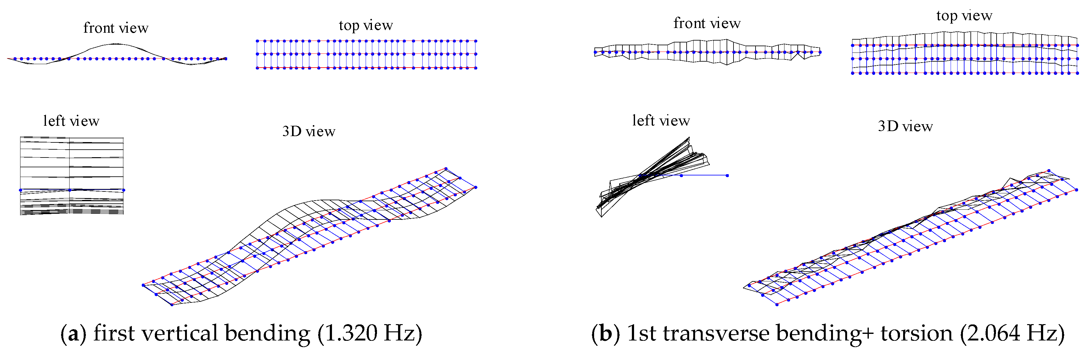
| 1 | 1.318 | 1.320 | 0.60 | −0.160 | 0.999 | 1st VB |
| 2 | NA | 1.705 | 2.02 | NA | NA | 1st longitudinal |
| 3 | 2.053 | 2.064 | 1.78 | −0.568 | 0.985 | 1st TB+ torsion |
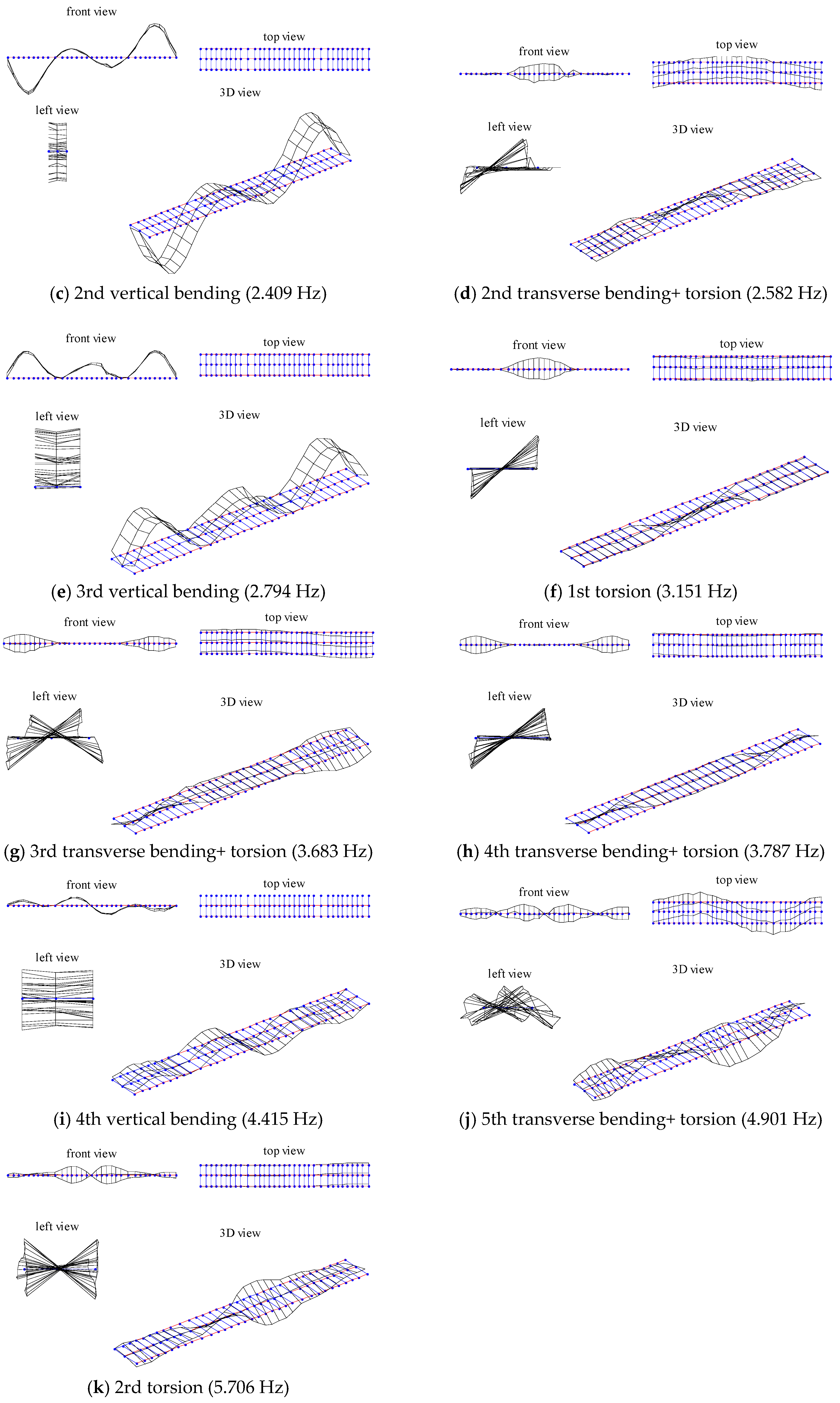
| 4 | 2.402 | 2.409 | 1.08 | −0.299 | 0.994 | 2nd VB |
| 5 | 2.563 | 2.582 | 2.90 | −0.726 | 0.943 | 2nd TB+ torsion |
| 6 | 2.789 | 2.794 | 1.42 | −0.175 | 0.971 | 3rd VB |
| 7 | 3.136 | 3.151 | 1.99 | −0.465 | 0.993 | 1st torsion |
| 8 | 3.656 | 3.683 | 1.20 | −0.744 | 0.941 | 3rd TB+ torsion |
| 9 | 3.775 | 3.787 | 1.53 | −0.323 | 0.978 | 4th TB+ torsion |
| 10 | 4.403 | 4.415 | 2.66 | −0.281 | 0.969 | 4th VB |
| 11 | 4.879 | 4.901 | 1.55 | −0.463 | 0.942 | 5th TB+ torsion |
| 12 | 5.657 | 5.706 | 1.41 | −0.843 | 0.939 | 2nd torsion |
| Mode No. | Phase 1 | Phase 2 | Phase 3 | Mode Description | |||
|---|---|---|---|---|---|---|---|
| Frequency /Hz | Damping ratio/% | Frequency /Hz | Damping Ratio/% | Frequency /Hz | Damping Ratio/% | ||
| 1 | 1.57 | 0.21 | 1.42 | 0.35 | 1.32 | 0.60 | 1st VB |
| 2 | 2.07 | 0.68 | 1.90 | 1.91 | 1.71 | 2.02 | 1st longitudinal |
| 3 | 2.38 | 0.62 | 2.24 | 1.29 | 2.06 | 1.78 | 1st TB+ torsion |
| 4 | 2.76 | 0.48 | 2.58 | 0.69 | 2.41 | 1.08 | 2nd VB |
| 5 | 3.16 | 1.12 | 2.84 | 2.20 | 2.58 | 2.90 | 2nd TB+ torsion |
| 6 | 3.31 | 0.35 | 2.99 | 0.89 | 2.79 | 1.42 | 3rd VB |
| 7 | 3.80 | 0.78 | 3.33 | 1.51 | 3.15 | 1.99 | 1st torsion |
| 8 | 4.18 | 0.64 | 3.65 | 1.71 | 3.68 | 1.20 | 3rd TB+ torsion |
| 9 | 4.52 | 0.52 | 3.96 | 0.80 | 3.79 | 1.53 | 4th TB+ torsion |
| 10 | 5.49 | 0.67 | 4.85 | 1.47 | 4.42 | 2.66 | 4th VB |
| 11 | 6.22 | 0.73 | 5.57 | 1.07 | 4.90 | 1.55 | 5th TB+ torsion |
| 12 | 7.23 | 0.85 | 6.44 | 1.03 | 5.71 | 1.41 | 2nd torsion |
| Mode No. | Calculated [Hz] | Measured [Hz] | Variance/% | |||
|---|---|---|---|---|---|---|
| M1 | M2 | T1 | T2 | (M1–T1)/T1 | (M2–T2)/T2 | |
| 1 | 4.82 | 4.39 | 5.00 | 4.61 | −3.55 | −4.68 |
| 2 | 8.70 | 8.41 | 9.21 | 8.71 | −5.58 | −3.49 |
| 3 | 8.80 | 8.59 | 9.42 | 8.92 | −6.59 | −3.72 |
| Mode No. | fm | fs | Variance (%) | Mode Description |
|---|---|---|---|---|
| 1 | 1.32 | 1.36 | 3.58 | 1st VB |
| 2 | 1.71 | 1.72 | 1.04 | 1st longitudinal |
| 3 | 2.06 | 1.97 | −4.50 | 1st TB+ torsion |
| 4 | 2.41 | 2.44 | 1.18 | 2nd VB |
| 5 | 2.58 | 2.65 | 2.63 | 2nd TB+ torsion |
| 6 | 2.79 | 2.88 | 3.12 | 3rd VB |
| 7 | 3.15 | 3.24 | 2.96 | 1st torsion |
| 8 | 3.68 | 3.75 | 1.80 | 3rd TB+ torsion |
| 9 | 3.79 | 3.88 | 2.64 | 4th TB+ torsion |
| 10 | 4.42 | 4.60 | 4.21 | 4th VB |
| 11 | 4.9 | 4.99 | 1.72 | 5th TB+ torsion |
| 12 | 5.71 | 5.99 | 4.98 | 2nd torsion |
| Calibration Items | Level −1 | Level 0 | Level 1 | Δi |
|---|---|---|---|---|
| Elastic modulus of steel plate Es (1011 N/m2) | 1.85 | 2.06 | 2.26 | 0.21 |
| Mass density of the steel plate ρs (kg/m3) | 7065 | 7850 | 8635 | 785 |
| Mass density of asphalt pavement ρa (kg/m3) | 1840 | 2300 | 2760 | 460 |
| Elastic modulus of bridge piers Ec (1010 N/m2) | 2.93 | 3.25 | 3.58 | 0.33 |
| Longitudinal stiffness of expansion joints k (106 N/m) | 1.8 | 2.0 | 2.2 | 0.2 |
| Calibration Items | Initial Value | After Updating | Variance |
|---|---|---|---|
| ρs (kg/m3) | 7850 | 8493.8 | 8.2% |
| Es (Pa) | 2.06 × 10¹¹ | 1.90 × 10¹¹ | −7.7% |
| Ec (Pa) | 3.25 × 10¹⁰ | 3.24 × 10¹⁰ | −0.03% |
| ρa (kg/m3) | 2300 | 1840.1 | −19.9% |
| k (N/m) | 2 × 10⁶ | 1.91 × 10⁶ | −4.3% |
| Mode No. | fm | fs′ | Initial Error (%) | Error After Updating (%) |
|---|---|---|---|---|
| 1 | 1.32 | 1.31 | 3.58 | −0.11 |
| 2 | 1.71 | 1.70 | 1.04 | 0.10 |
| 3 | 2.06 | 1.96 | −4.50 | −5.05 |
| 4 | 2.41 | 2.36 | 1.18 | −2.06 |
| 5 | 2.58 | 2.61 | 2.63 | 1.16 |
| 6 | 2.79 | 2.79 | 3.12 | −0.27 |
| 7 | 3.15 | 3.14 | 2.96 | −0.06 |
| 8 | 3.68 | 3.67 | 1.80 | −0.27 |
| 9 | 3.79 | 3.80 | 2.64 | 0.27 |
| 10 | 4.42 | 4.44 | 4.21 | 0.53 |
| 11 | 4.9 | 4.86 | 1.72 | −0.90 |
| 12 | 5.71 | 5.84 | 4.98 | 2.40 |
| Mode No. | Phase 1 | Phase 2 | Phase 3 | Mode Description | |||||||||
|---|---|---|---|---|---|---|---|---|---|---|---|---|---|
| fm /Hz | fs /Hz | Variance /% | MAC | fm /Hz | fs /Hz | Variance /% | MAC | fm /Hz | fs /Hz | Variance /% | MAC | ||
| 1 | 1.57 | 1.55 | −1.05 | 0.999 | 1.42 | 1.44 | 1.59 | 0.999 | 1.32 | 1.31 | −0.11 | 0.999 | 1st VB |
| 2 | 2.07 | 1.99 | −3.90 | - | 1.90 | 1.86 | −2.22 | - | 1.71 | 1.70 | 0.10 | - | 1st longitudinal |
| 3 | 2.38 | 2.45 | 3.10 | 0.964 | 2.24 | 2.29 | 2.01 | 0.965 | 2.06 | 1.96 | −5.05 | 0.958 | 1st TB+ torsion |
| 4 | 2.76 | 2.69 | −2.45 | 0.991 | 2.58 | 2.53 | −2.07 | 0.989 | 2.41 | 2.36 | −2.06 | 0.983 | 2nd VB |
| 5 | 3.16 | 3.34 | 5.60 | 0.877 | 2.84 | 2.91 | 2.46 | 0.867 | 2.58 | 2.61 | 1.16 | 0.848 | 2nd TB+ torsion |
| 6 | 3.31 | 3.23 | −2.35 | 0.995 | 2.99 | 2.91 | −2.67 | 0.992 | 2.79 | 2.79 | −0.27 | 0.987 | 3rd VB |
| 7 | 3.8 | 3.95 | 3.90 | 0.931 | 3.33 | 3.18 | −4.53 | 0.922 | 3.15 | 3.14 | −0.06 | 0.921 | 1st torsion |
| 8 | 4.18 | 4.07 | −2.70 | 0.956 | 3.65 | 3.84 | 5.13 | 0.956 | 3.68 | 3.67 | −0.27 | 0.943 | 3rd TB+ torsion |
| 9 | 4.52 | 4.64 | 2.60 | 0.947 | 3.96 | 4.06 | 2.40 | 0.942 | 3.79 | 3.80 | 0.27 | 0.931 | 4th TB+ torsion |
| 10 | 5.49 | 5.33 | −2.85 | 0.979 | 4.85 | 5.06 | 4.41 | 0.975 | 4.42 | 4.44 | 0.53 | 0.965 | 4th VB |
| 11 | 6.22 | 6.45 | 3.65 | 0.866 | 5.57 | 5.75 | 3.21 | 0.865 | 4.9 | 4.86 | −0.90 | 0.849 | 5th TB+ torsion |
| 12 | 7.23 | 7.53 | 4.10 | 0.943 | 6.44 | 6.64 | 3.09 | 0.943 | 5.71 | 5.84 | 2.40 | 0.939 | 2nd torsion |
Disclaimer/Publisher’s Note: The statements, opinions and data contained in all publications are solely those of the individual author(s) and contributor(s) and not of MDPI and/or the editor(s). MDPI and/or the editor(s) disclaim responsibility for any injury to people or property resulting from any ideas, methods, instructions or products referred to in the content. |
© 2024 by the authors. Licensee MDPI, Basel, Switzerland. This article is an open access article distributed under the terms and conditions of the Creative Commons Attribution (CC BY) license (https://creativecommons.org/licenses/by/4.0/).
Share and Cite
Chen, J.; He, W.; Sun, C.; Hou, S.; Chen, J.; Wang, Z. Vibration Measurement and Numerical Simulation of the Effect of Non-Structural Elements on Dynamic Properties of Large-Span Structures. Buildings 2024, 14, 3589. https://doi.org/10.3390/buildings14113589
Chen J, He W, Sun C, Hou S, Chen J, Wang Z. Vibration Measurement and Numerical Simulation of the Effect of Non-Structural Elements on Dynamic Properties of Large-Span Structures. Buildings. 2024; 14(11):3589. https://doi.org/10.3390/buildings14113589
Chicago/Turabian StyleChen, Jialiang, Wei He, Congbo Sun, Sen Hou, Junjie Chen, and Zhe Wang. 2024. "Vibration Measurement and Numerical Simulation of the Effect of Non-Structural Elements on Dynamic Properties of Large-Span Structures" Buildings 14, no. 11: 3589. https://doi.org/10.3390/buildings14113589
APA StyleChen, J., He, W., Sun, C., Hou, S., Chen, J., & Wang, Z. (2024). Vibration Measurement and Numerical Simulation of the Effect of Non-Structural Elements on Dynamic Properties of Large-Span Structures. Buildings, 14(11), 3589. https://doi.org/10.3390/buildings14113589