Article

Experimental Study on the Mechanical Properties of Squat RC Shear Walls with Corrosion Along the Base

1
China Nuclear Power Technology Co., Ltd., Beijing 100193, China
2
School of Civil Engineering, Sun Yat-sen University, Guangzhou 510275, China
*
Author to whom correspondence should be addressed.
Buildings 2024, 14(11), 3409; https://doi.org/10.3390/buildings14113409
Submission received: 25 August 2024 / Revised: 21 October 2024 / Accepted: 25 October 2024 / Published: 26 October 2024
(This article belongs to the Special Issue Research on the Durability of Reinforced Concrete Structures)

Abstract

:
In corrosive environments containing chloride and sulfate, the corrosion of steel bars is common along the base of squat RC shear walls (SRCSW) due to problems such as construction quality, concrete stress concentration, local defects, and accumulation of water and corrosive media. In this paper, three SRCSWs are designed and constructed and their mechanical properties assessed. One side of each SRCSW was exposed to a corrosive environment for 70 days, while the other side was subject to the same conditions over different corrosion times (i.e., 0 day, 42 days, and 70 days). Then, the corrosion-induced cracking process, the mechanical properties of SRCSWs corroded along the base, the relationship between the mass loss of total steel bars (MLTSB) in the corroded area and the wall mechanical properties, and the relationship between the average width of corrosion-induced cracks (CICs) and the wall mechanical properties were studied through an accelerated corrosion test and a loading failure test. The results indicate that the area of corrosion-induced cracking on SRCSWs increased with the corrosion time, and the cracking area on the different SRCSWs was approximately identical when the SRCSWs were exposed to the same corrosion time. When the degree of corrosion was different, the loading failure characteristics of the SRCSWs were obviously different, but the failure mode always corresponded to shear failure. The load–displacement curves of the SRCSWs with different degrees of corrosion along the base basically coincided and were linear when the loading was in the elastic stage. Compared to SW-1, the peak load of SW-2 decreased by 4.0%, but that of SW-3 increased by 2.7%. Compared to SW-1, the yield loads of SW-2 and SW-3 decreased by 22.4% and 11.8%, respectively. When the MLTSB increased from 13.05% to 16.71%, the crack, yield, and peak loads of the SRCSWs corroded along the base decreased by 8.8%, 22.4%, and 6.8%, respectively. The cracking, yield, and peak loads of the SRCSWs corroded along the base decreased linearly with the increase in MLTSB and the average width of the CICs, and the corresponding fitting relations were established. The results of this study can serve as a reference for the durability design of SRCSWs in corrosive environments.

1. Introduction

China has a long coastline, and many coastal building structures are affected by salt hazards such as chloride and sulfate which result in a gradual decrease in their structural safety and serviceability [1,2,3,4]. RC shear walls have good lateral resistance and are widely used in multi-storey and high-rise building structures [5,6], owing to the alkaline substances with a pH value of 12.5–13.5 in the pores of hydrated cement slurry which can prevent the steel bars from experiencing corrosion [7,8]. After chloride ions in the external environment invade the interior of the concrete, they continuously accumulate on the surface of steel bars. When the chloride ion concentration reaches a threshold value, the passivation film on the surface of the steel bars becomes damaged, causing corrosion [9,10]. The speed and degree of corrosion of steel bars in RC shear walls can be affected by many factors, like the concentration of chloride ions, temperature, relative humidity, construction quality, and loads. Due to design defects, the insufficient thickness of the concrete cover leads to a faster penetration speed of chloride ions toward the surface of the steel bars. In addition, stress cracks develop faster on the surface of the concrete, and the expansion of the corroded steel bars underneath causes the concrete to further crack due to the insufficient concrete cover thickness. After the concrete cover becomes damaged, the invasion of chloride ions becomes easier, thereby exposing the steel bars in RC shear walls in coastal environments to corrosion [11,12,13,14,15].
After the corrosion, the stress concentration on the surface of RC structures along the steel bars augments and cracks form due to the expansion of the steel bars caused by the corrosion, in turn resulting in the peeling of the concrete cover and in a reduction of concrete strength [4,16]. Meanwhile, the mass loss of corroded steel bars results in a significant variation in the shape of the stress–strain curve, leading to a decrease in the sectional area, strength, and ductility of steel bars [17,18,19]. In addition, the bond performance between the steel bars and the concrete deteriorates as a result of the corrosion. Furthermore, corrosion decreases stirrup restraint ability [20], deteriorating the bearing and deformation capacities, alongside the energy dissipation capacity of RC structures [21,22]. Therefore, the RC shear wall is a type of RC structure, with the corrosion of steel bars not only affecting the durability and the service life [23] of RC shear walls, but also reducing their bearing capacity [24] and seismic properties [21,25].
Squat RC shear walls (SRCSWs), owing to their high lateral stiffness and bearing capacity, are widely adopted for construction along the bottom of large space structures, nuclear power plants, etc. [5,6]. Shear failure is the main failure mode of SRCSWs, while the main failure mode of high RC shear walls is bending failure [26,27]. Therefore, the mechanical properties of SRCSWs are obviously different from those of high RC shear walls. The mechanical properties of SRCSWs are affected by many factors, such as concrete strength [28], axial compression ratio [29], aspect ratio [30], reinforcement ratio [31], and the form of the edge constraint components. On account of the brittle failure of SRCSWs, some researchers have conducted extensive research on their mechanical properties. Rao [32] found that failures of SRCSWs generally manifested first in the wall panels, and then shear failure would occur in the edge-constrained members. Shao et al. [33] conducted experimental research on seven SRCSWs and developed a practical calculation formula to test the ultimate strength of shear walls. Guo et al. [34,35] proposed calculation models of shear bearing capacity and stiffness for SRCSWs with and without openings and peripheral frames by using the equivalent diagonal compression method. Thomson et al. [36] introduced a simplified model which could simulate the failure of SRCSWs under horizontal loads. Salonikios [37] designed RC shear walls with aspect ratios of 1.0 and 1.5 and investigated the shear strength and deformation of the walls. Massone [38] improved the MVLEM element with multiple vertical bars and proposed a shear-bending model of the strength of SRCSWs which could better predict their shear deformation performance.
Studies on the mechanical properties and seismic properties of corroded SRCSWs have been conducted by some researchers. Zheng et al. [5] found that, with an increase in the corrosion rate of the lateral distribution reinforcement from 0% to 16.56%, the bearing capacity, deformation capacity, ductility, and other aspects of corroded SRCSWs showed different degrees of degradation, with the bearing capacity and ductility weakened by 12.6% and 23.0%, respectively. Zheng et al. [29] found that, as the axial compression ratio increased, the cracking load, yield load, and peak load of the corroded SRCSWs increased. Zheng et al. [39] confirmed that reducing the spacing of the horizontally distributed steel bars could decrease the degree of shear failure of corroded SRCSWs and improve the bearing capacity, ductility, and energy dissipation capacity of corroded SRCSWs in different degrees, with the increase in ductility being the largest. Zheng et al. [40] indicated that the rigidity, ductility, and energy dissipation capacity of corroded SRCSWs under offshore atmospheric conditions decreased with the increase in the width of corrosion cracks. Many research results with important scientific value and practical engineering significance have been obtained by the above researchers. However, the above studies have all been conducted on shear walls, with the overall corrosion attained through simulated corrosive environments. As it is known to all, the actual service process of the building structures is not like this. The shear walls are directly corroded by corrosive substances such as chloride salts on the side facing the external environment, and this side often corrodes first. Problems such as construction quality, concrete stress concentration, local defects, and concrete cracking often exist along the base of SRCSWs.
As a result, all the problems above lead to the corrosion occurring first in the internal environment of shear walls, but not on their exterior. Nowadays, there is a lack of research on the mechanical properties of SRCSWs presenting corrosion along the base. To fill this research gap, firstly, three SRCSWs were designed and prepared in this study. Then, the accelerated corrosion test and the loading failure test were conducted on the SRCSWs. In addition, the corrosion-induced cracking, loading failure, and load–displacement curves of SRCSWs with corrosion along the base were studied. Finally, the relationship between the mechanical properties of SRCSWs and the mass loss of total steel bars (MLTSB) in the corroded area at the base, and the relationship between the mechanical properties and the average width of corrosion-induced cracks (CICs) were analyzed.

2. Experimental Program

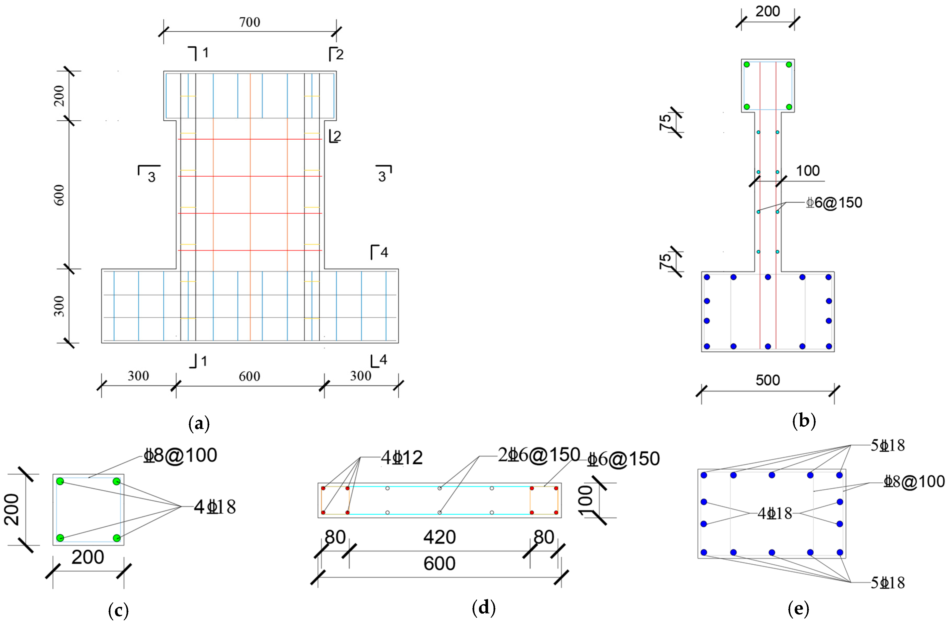
2.1. Design of SRCSWs

According to the Chinese Standard GB 50010 [41], three SRCSW specimens were designed and constructed in this experiment. The shear span ratio of specimens was designed as 1.17, and the thickness of the concrete cover, width, thickness, and height of the specimens were 10 mm, 600 mm, 100 mm, and 600 mm, respectively. PO cement with a strength grade of 42.5R was used to prepare the concrete with a strength grade of C40, and the concrete was designed according to the Chinese Standard JGJ 55 [42]. Steel bars, with a strength grade of HRB400, were used in the specimens. The sizes and reinforcement of the specimens are depicted in Figure 1.
The arrangement of strain gauges can be seen in Figure 2. The strain gauges were attached to the vertically distributed steel bars within the embedded column at the bottom of the wall, to the stirrups, and to the horizontally distributed steel bars. The strain gauges were used to assist in judging the stress state of the specimens during the loading process.
In this test, the type, placement, and number of steel bars from the three specimens were the same. When tying the skeleton of the steel bars, firstly, the steel bars in the bottom beam were tied. Then, the steel bars in the wall and top beam were tied. This process is shown in Figure 3.
The bottom beam of the specimens was shaped with a wooden formwork according to its size, and ordinary concrete was then poured in. In the process of pouring, vibratory bars were used to vibrate the concrete. Then, the concrete for the wall and top beam was poured and vibrated. This process is shown in Figure 4. After the pouring of the concrete, the specimens were cured under standard conditions for 28 days. As per the Chinese Standard GB 50081 [43], the cubic compressive strength of the concrete was tested after 28 days of curing, and a value of 49.7 MPa was obtained.

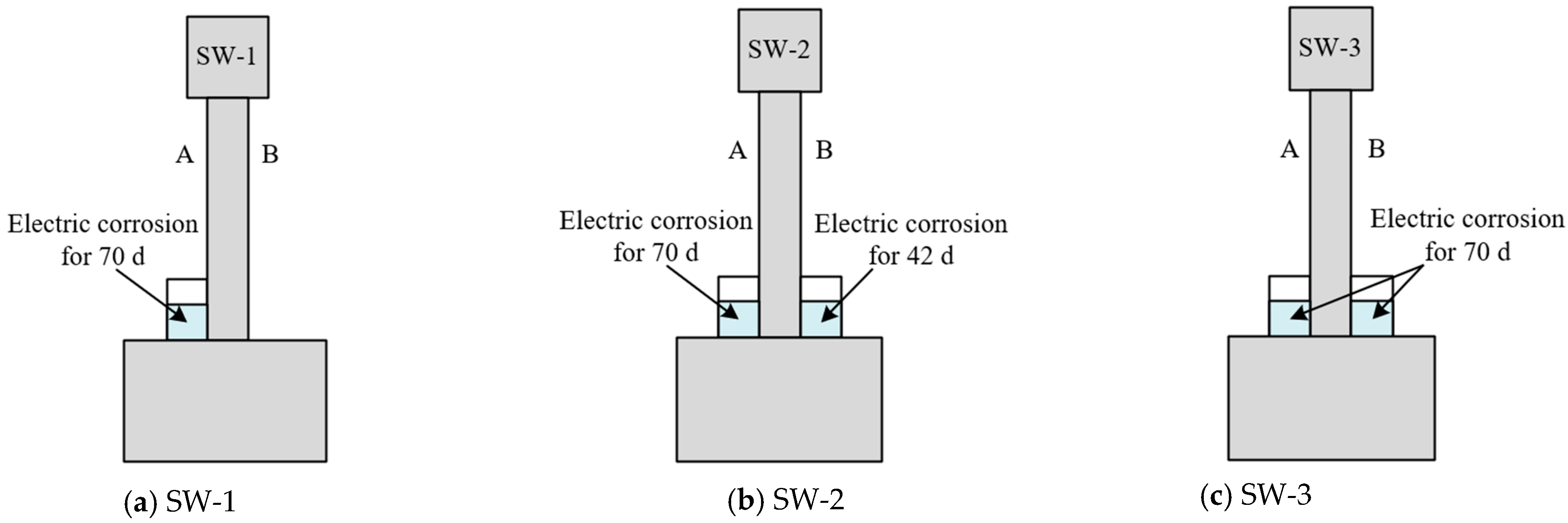
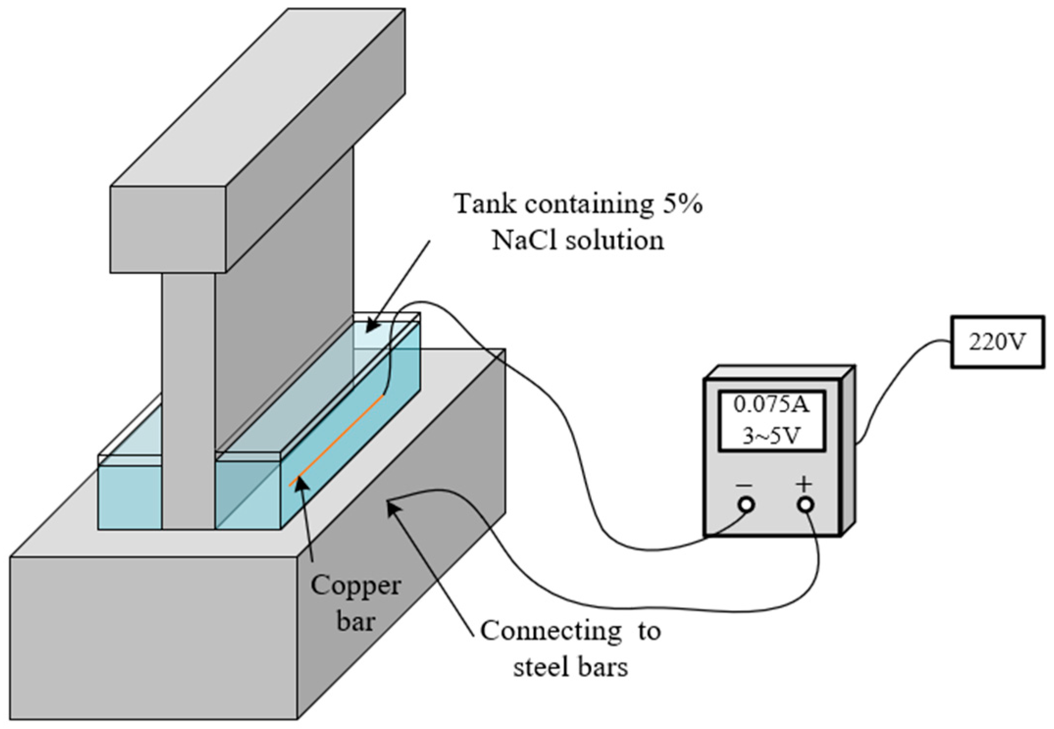
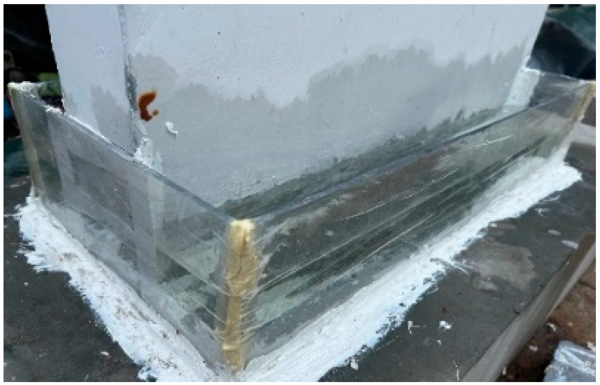
2.2. Accelerated Corrosion Test

To study the effect of the degree of steel corrosion on the shear capacity of SRCSWs in chloride environments, the three SRCSW specimens were exposed to various corrosion conditions, which were numbered SW-1, SW-2, and SW-3, respectively. For the SW-1 condition, the designed corrosion height of the side A was set to 90 mm and side A was subject to a 70-day corrosion experiment, while side B was not exposed to corrosive conditions. For the SW-2 and SW-3 conditions, the designed corrosion height on both sides of the SRCSWs was set to 90 mm. However, compared to the SW-3 condition, where corrosion was promoted on both sides of the SRCSWs for 70 days, the corrosion time under the SW-2 condition was 70 days for side A and 42 days for side B. The specific corrosion conditions are shown in Table 1 and Figure 5.
The electrochemical corrosion method was adopted to accelerate the corrosion of steel bars. After curing, a tank containing NaCl solution with a mass fraction of 5% was positioned in the target corrosion area of the specimens in advance. Before accelerating corrosion through electricity, the specimens were allowed to soak in the NaCl solution for 72 h. Therefore, by the end of the 72 h, the solution had sufficiently penetrated deep into the specimens to form a closed loop with the steel bars, shown in Figure 6 and Figure 7. When the acceleration of corrosion by electricity begun, the copper rod in the tank served as the cathode of the circuit. The steel bars in the specimens 90 mm off the bottom of the wall (SW-2 and SW-3 are used as examples here, and SW-1 was connected only to the steel bars near the corroded side) acted as the anode of the circuit. Many researchers have indicated that the current density should be less than 200 μA/cm2 during the process of accelerated corrosion, so that the corrosion characteristics of the steel bars remain similar to those under natural corrosion conditions [44,45,46]. For this reason, the current density in this experiment was set to 180 μA/cm2. During the accelerated corrosion test, the condition of the specimens was recorded daily, as shown in Figure 8. After the accelerated corrosion test, the width and length of the CICs of SRCSW specimens were measured, and the distribution of the CICs was also recorded.

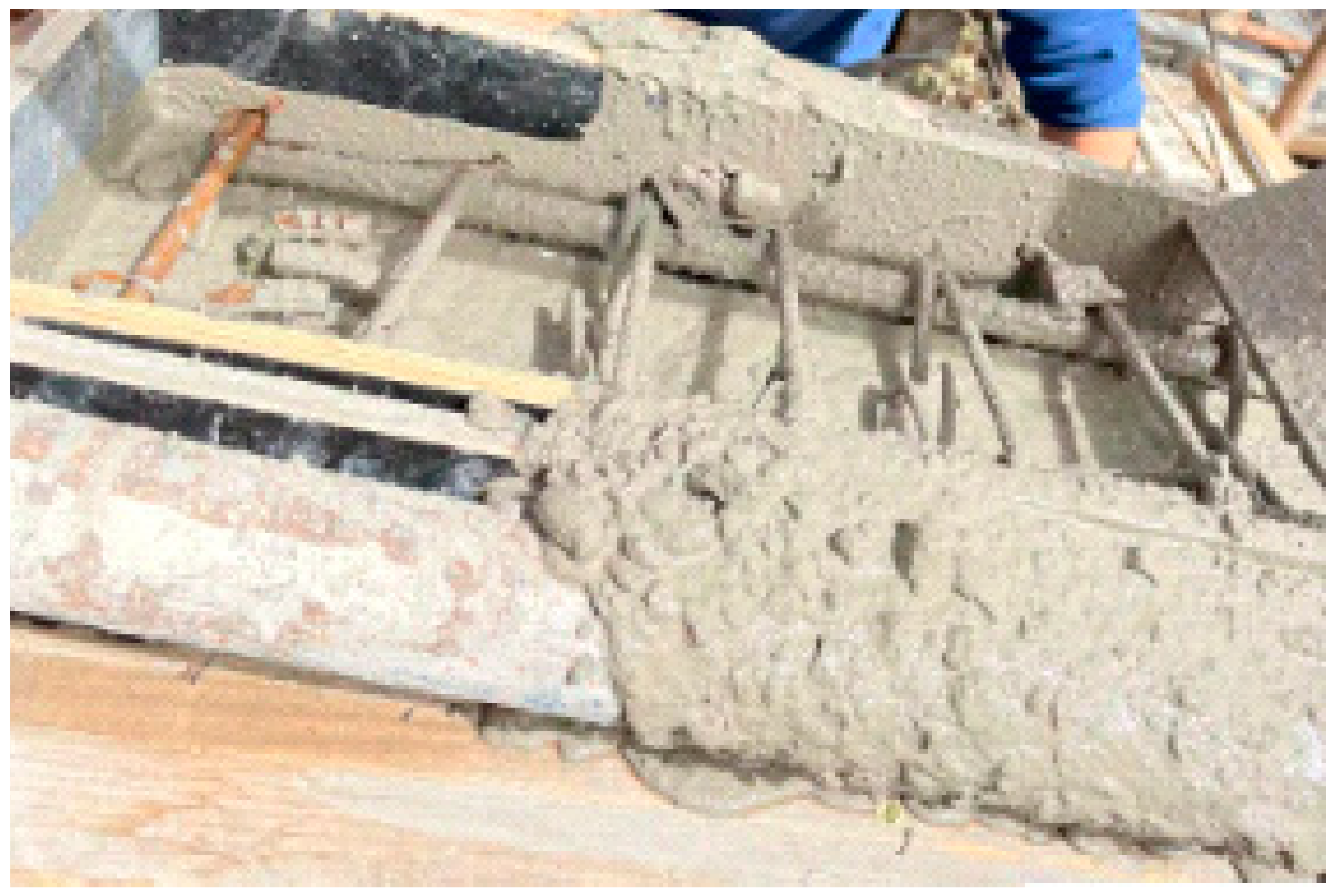
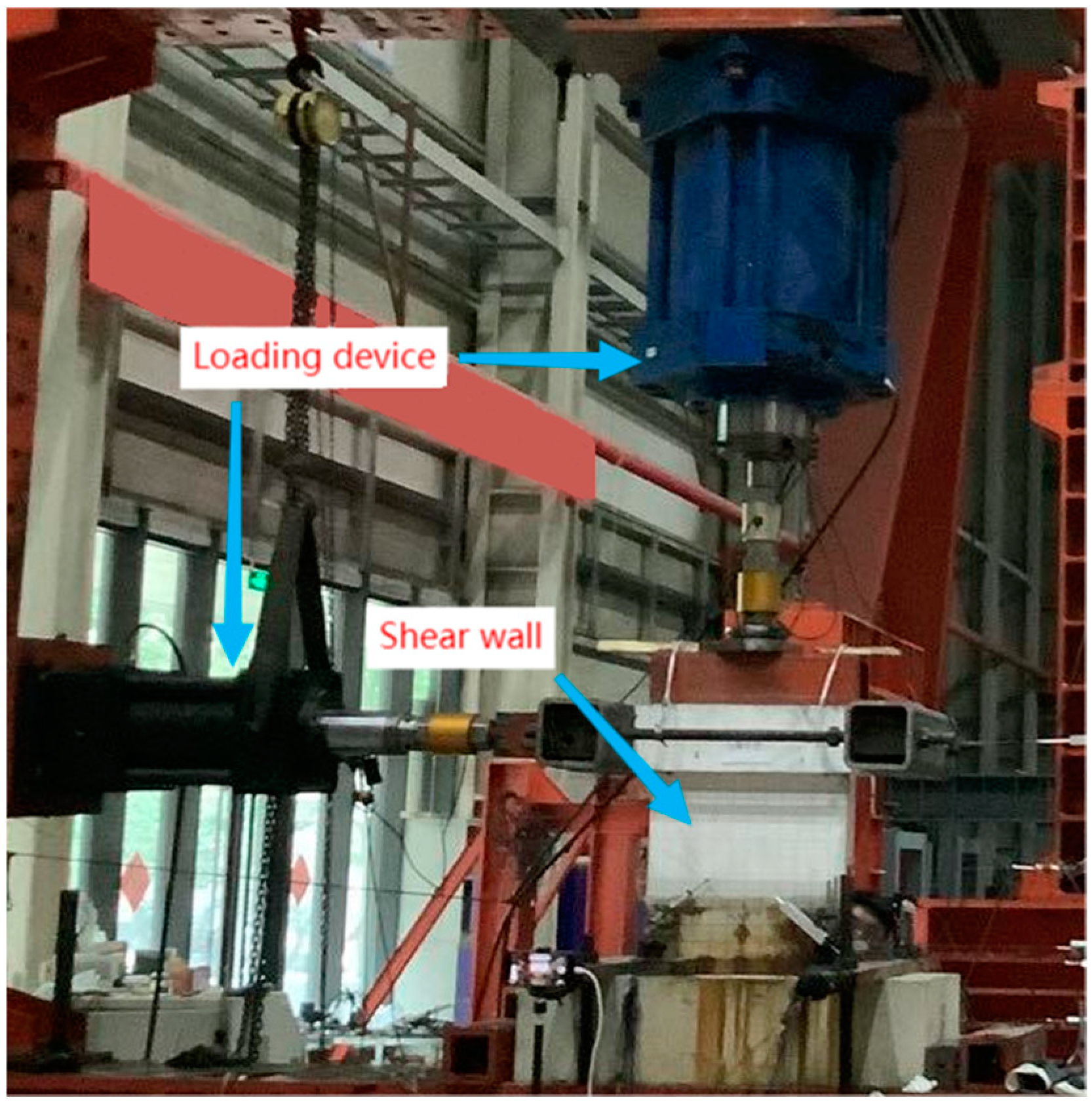
2.3. Loading Failure Test

Before the formal load, the preload needed to be applied to the corroded SRCSWs to ensure that all loading equipment, measuring instruments, and data acquisition systems functioned properly. As per the Chinese Standard GB 50152 [47], the vertical load was applied to the corroded SRCSWs before the formal loading. Then, the loading method controlled through displacement was adopted, and the shear capacity was measured. Based on the Chinese Standard GB 50010 [41], the compressive capacity of the SRCSWs before corrosion could be calculated, and the value was 1379.5 kN. During the process of loading, the vertical load applied to the SRCSWs was 10% of the compressive capacity, namely 137.95 kN. That is to say that the axial compression ratio was 10%. During the pre-test, 10% of the vertical load was taken as the value of the pre-test load. The process of loading and unloading was repeated twice. During the formal loading, the horizontal displacement started from 0 and the load was applied slowly. The displacement was applied in the order of 0.35 mm, 0.70 mm, 1.05 mm, 1.40 mm, 2.10 mm, 2.80 mm, 3.50 mm, 4.20 mm, 4.90 mm, 5.60 mm, 7.00 mm, 8.40 mm, 9.80 mm, 11.20 mm, and 12.60 mm. When the horizontal load of the specimens dropped below 85% of its peak load, the specimens were considered to be damaged, and the test was terminated. If the specimens were damaged earlier than that, the test was terminated accordingly. The loading device is depicted in Figure 9, and the vertical loads were applied by electro-hydraulic jacks. All the forces, displacements, and strain signals were automatically collected by a computer through a data acquisition instrument.

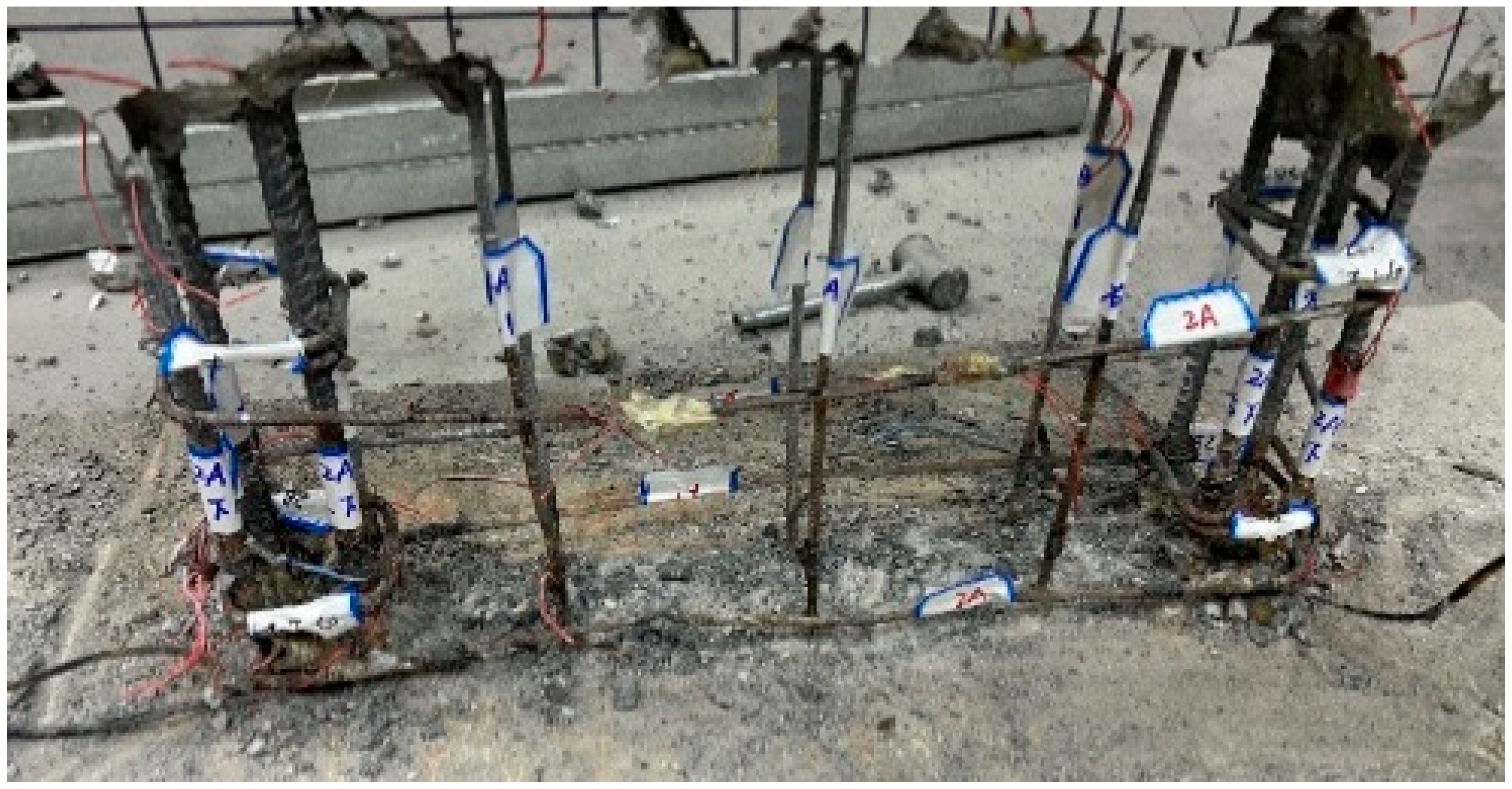
2.4. Measurement of Mass Loss of Steel Bars

After the loading failure test was done, a drilling rig was used to destroy the concrete in the locally corroded area of the SRCSWs. Then, the internal, corroded steel bars were numbered and cut out using a cutting machine, as shown in Figure 10. Obvious evidence of corrosion of the steel bars was found, indicating that the horizontally distributed steel bars were the most severely corroded, with a danger of corrosion fracture. Corrosion removal on the steel bars was carried out based on the Chinese Standard GB/T 50082 [48]. The concrete adhering to the surface of corroded steel bars was scraped with a knife and then the steel bars were pickled with 12% hydrochloric acid solution. After the corrosion products on the surface of the steel bars were cleared away, the surface of steel bars was first cleaned with tap water, then it was neutralized with saturated lime water, and then, again, washed with tap water. The cut steel bars after the removal of corrosion products are shown in Figure 11. The mass of the steel bars after the corrosion products were removed was measured by using an electronic scale with an accuracy of 0.01 g. Then, the mass loss of steel bars was calculated using Equation (1) [49,50]:
η s = m s m c m s × 100 %
where ηs is the mass loss of steel bars (%), ms is the mass of the steel bars before corrosion (g), and mc is the mass of the steel bars after corrosion (g).

3. Results and Discussion

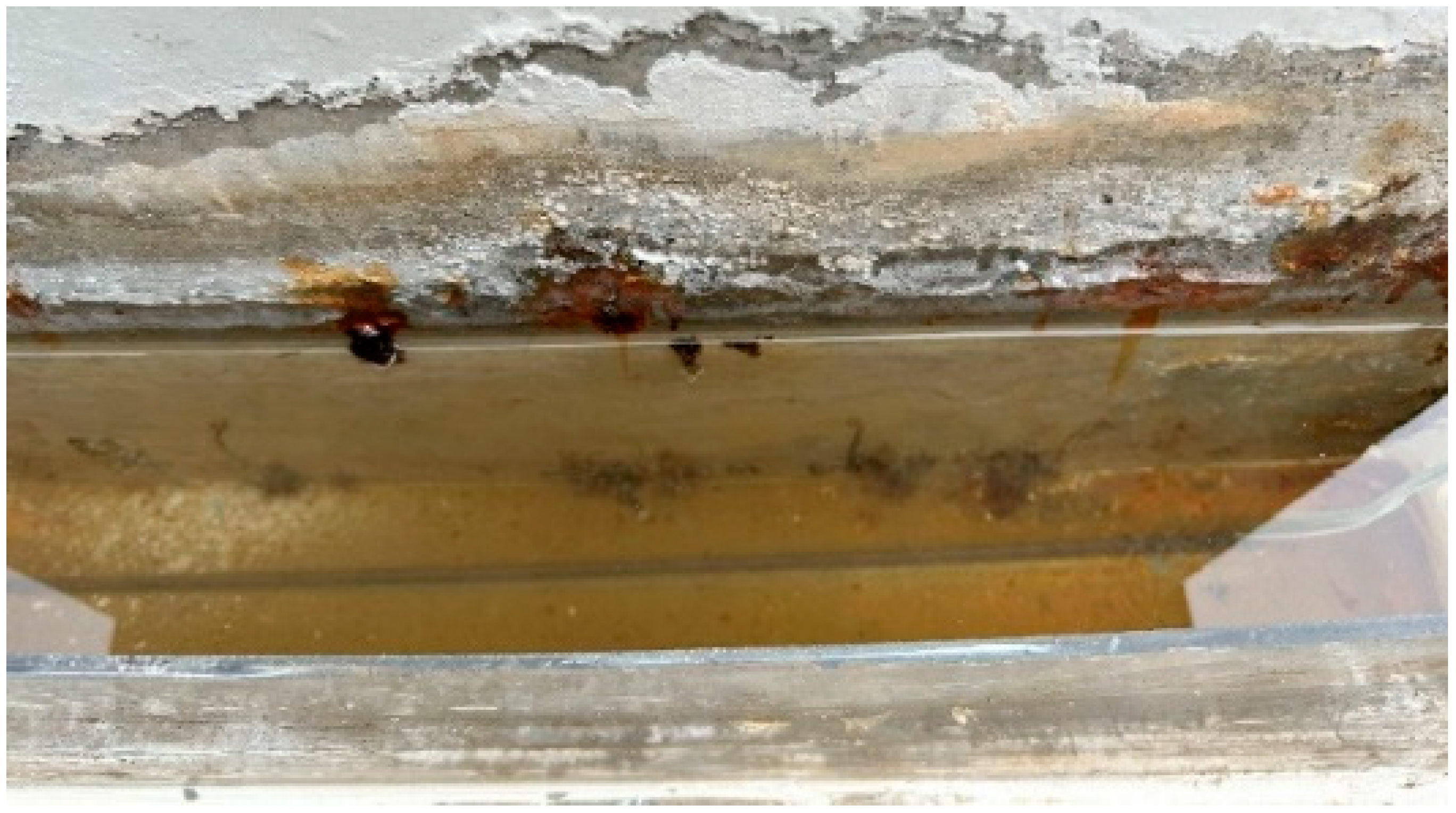
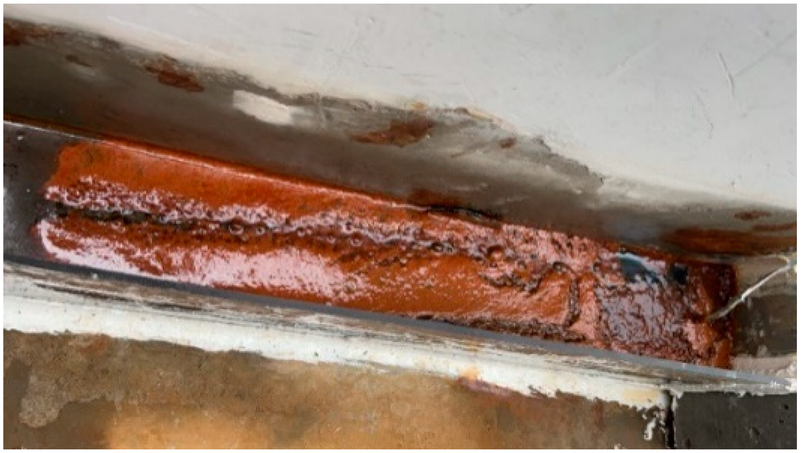
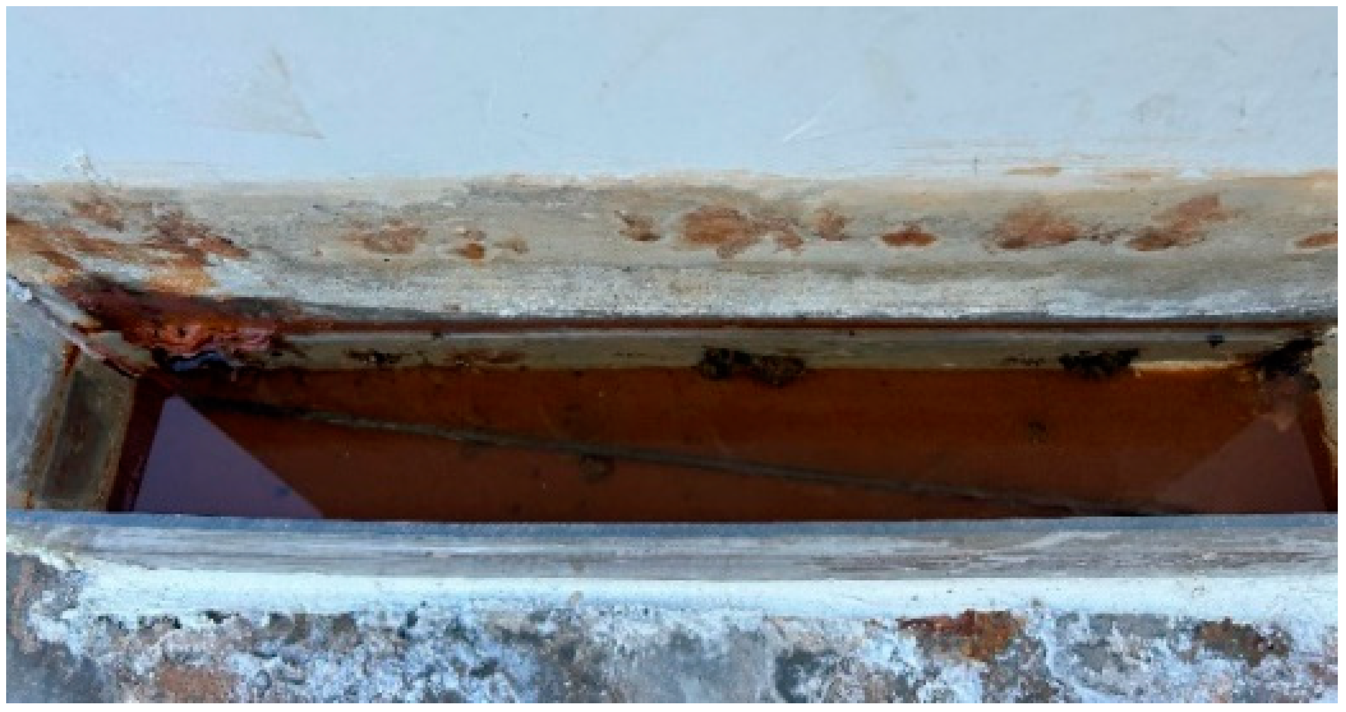
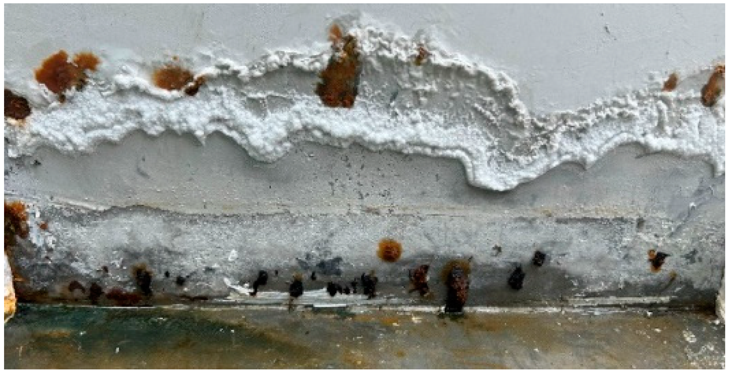
3.1. Corrosion Phenomenon of SRCSWs

When the current was constant, the circuit voltage fluctuated continuously, and this phenomenon persisted throughout the corrosion process. This was due to the corrosion of the steel bars causing internal cracking in the SRCSWs, reducing the resistance of SRCSWs and leading to constant voltage changes in the SRCSWs. At the beginning of the electrification process, small bubbles were produced continuously on the surface of the copper rod, but no other obvious phenomenon occurred, as shown in Figure 12. However, defects of construction, the unevenness of the concrete, as well as other problems existed in the walls. After a period of time (about 10 days), a small amount of white NaCl crystals was precipitated in the upper part of the locally corroded area on the SRCSWs. In addition, corrosion spots developed on the surface of the walls in some areas, and corrosion products also appeared. Corrosion products started to accumulate consistently around corrosion expansion cracks or holes, and eventually formed a semicircular morphology attached to the surface of the walls. The solution gradually turned yellow due to the presence of corrosion products, as shown in Figure 13. As the corrosion time increased, the corrosion of the walls gradually became more serious. After substantial accumulation of reddish-brown corrosion products, these started to dissipate into the solution, and a large number of foamy reddish-brown corrosion products would start to float and then sink. Partially floating corrosion products accumulated on the surface of the solution, forming a thick layer of floating corrosion products, as depicted in Figure 14. After a period of time, more scattered corrosion products sank to the bottom of the tank due to gravity, forming a thick layer, as illustrated in Figure 15. When the tank was removed, the accumulation of corrosion products became attached to the surface of the walls nearing the locally corroded area. In addition, a substantial portion of the salt solution in the electrolyte also crystallized above the locally corroded area, as shown in Figure 16. The corrosion products were mainly black, yellow–brown, and red. Inside the relatively hard, black corrosion product piles, a small number of corrosion products that were not directly exposed to the air appeared to be dark green or yellow–green in color, as depicted in Figure 17.
Due to the presence of electrified devices and tanks during the corrosion process of the SRCSWs, the CICs could not be observed continuously. Therefore, during the process of the test, the tank was removed at intervals to observe the cracks. During the corrosion test, it was found that the CICs were mostly distributed within the area soaked in the tank. In addition, some cracks developed far from the main corrosion area, at about twice the height of the corrosion (90 mm). This was due to the presence of horizontally distributed steel bars near the 200 mm height mark, and the cracks at this height appeared earlier and developed relatively rapidly vertically, while the width of the cracks developed relatively slowly. The cracks first occurred around the location of the defects in the concrete within the corroded areas. Cracks also occurred in correspondence of horizontally distributed steel bars, stirrups, and vertically distributed steel bars. As the corrosion time increased, the small cracks gradually extended and penetrated deeper into the structure. Thus, long cracks formed, exhibiting the form of strips, rings, and a larger network. This was mainly due to the relatively low thickness of the concrete cover of the walls. The first cracks developed as a result of the corrosion-induced expansion of the steel bars or because of local defects. More channels for chloride ion transportation became available and the local corrosion of the steel bars became serious. Because of the loosening and dislocation of material occurring in the affected areas, the surrounding concrete became affected, with the concrete cover exhibiting a tendency to flake off. After 10 days of electrification, small cracks appeared in the specimens, all distributed along the vertical axis. This was mainly because the steel bars at the corresponding positions were vertically distributed and embedded within the cement column. The volume of the corroded steel bars expanded and the concrete on both sides became compressed, causing cracks to appear. In the wake of the increase in corrosion time, an obvious horizontal crack appeared in correspondence of the horizontally distributed steel bars.
The cracking area of each specimen can be calculated by using the width and length of the CICs. The cracking areas of the surfaces of SW-1B, SW-2B, and SW-3B showed an obvious linear relationship according to the final cracking condition of the SRCSWs. The surface of SW-1B was never in direct contact with the water in the tank, and no macroscopic cracks were observed; hence, the corrosion-induced cracking area of this wall was considered to be zero. The corrosion time for the surfaces of SW-1A, SW-2A, SW-3A, and SW-3B was the same. Except for SW-3A, the cracking areas of the other three walls were approximately equal. In addition, the cracking areas that were visible at the end of the test were compared, and it was found that the corrosion-induced cracking area of SW-2B was the smallest after only 42 days of electrification. The effect of the construction defects of the specimens was not considered. The phenomenon above indicates a correlation between the cracking area and the corrosion time, that is, with the increase in corrosion time, the corrosion-induced cracking area increased.

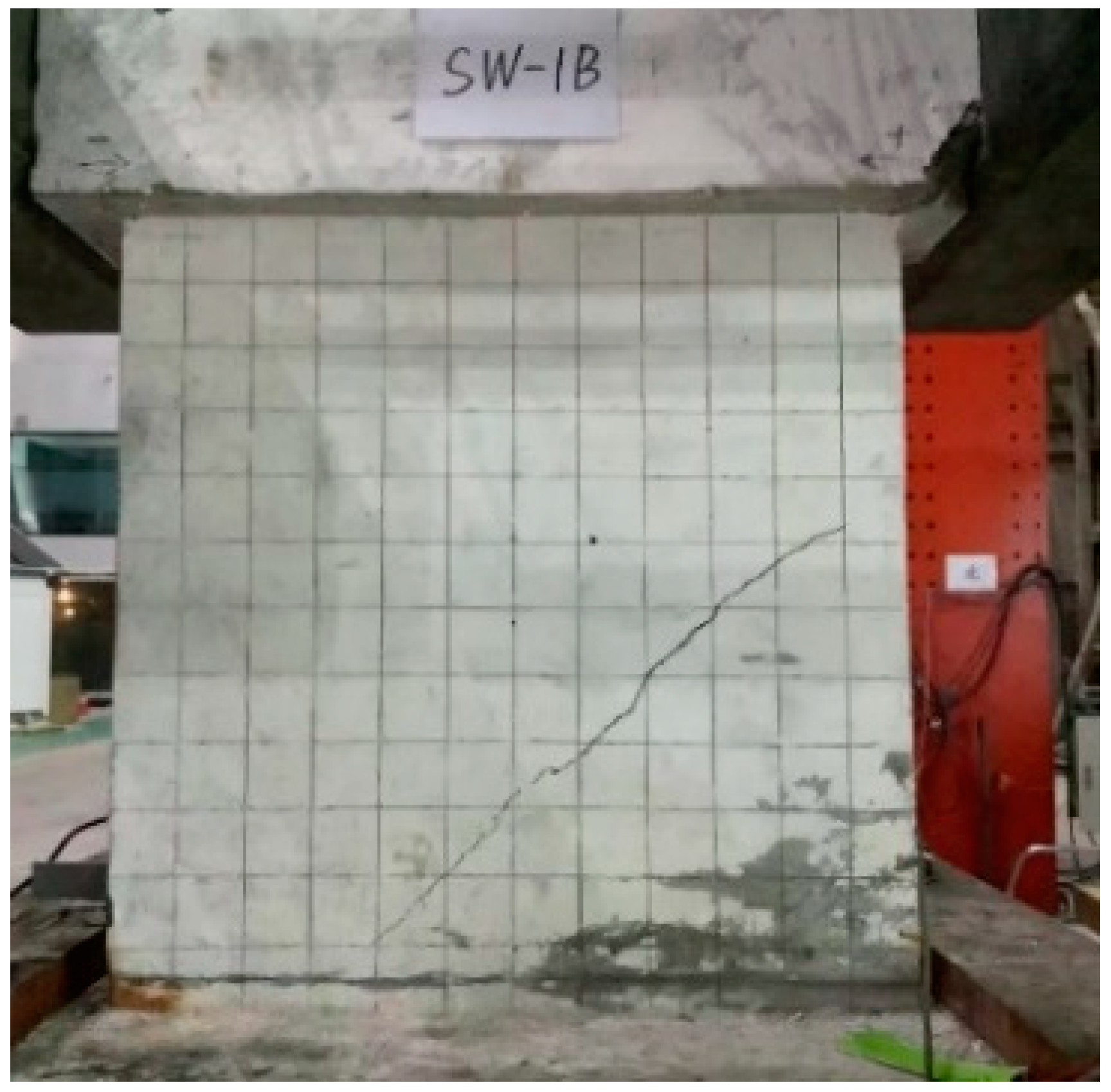
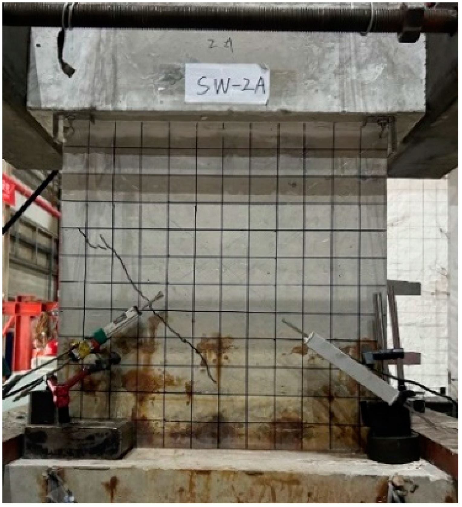
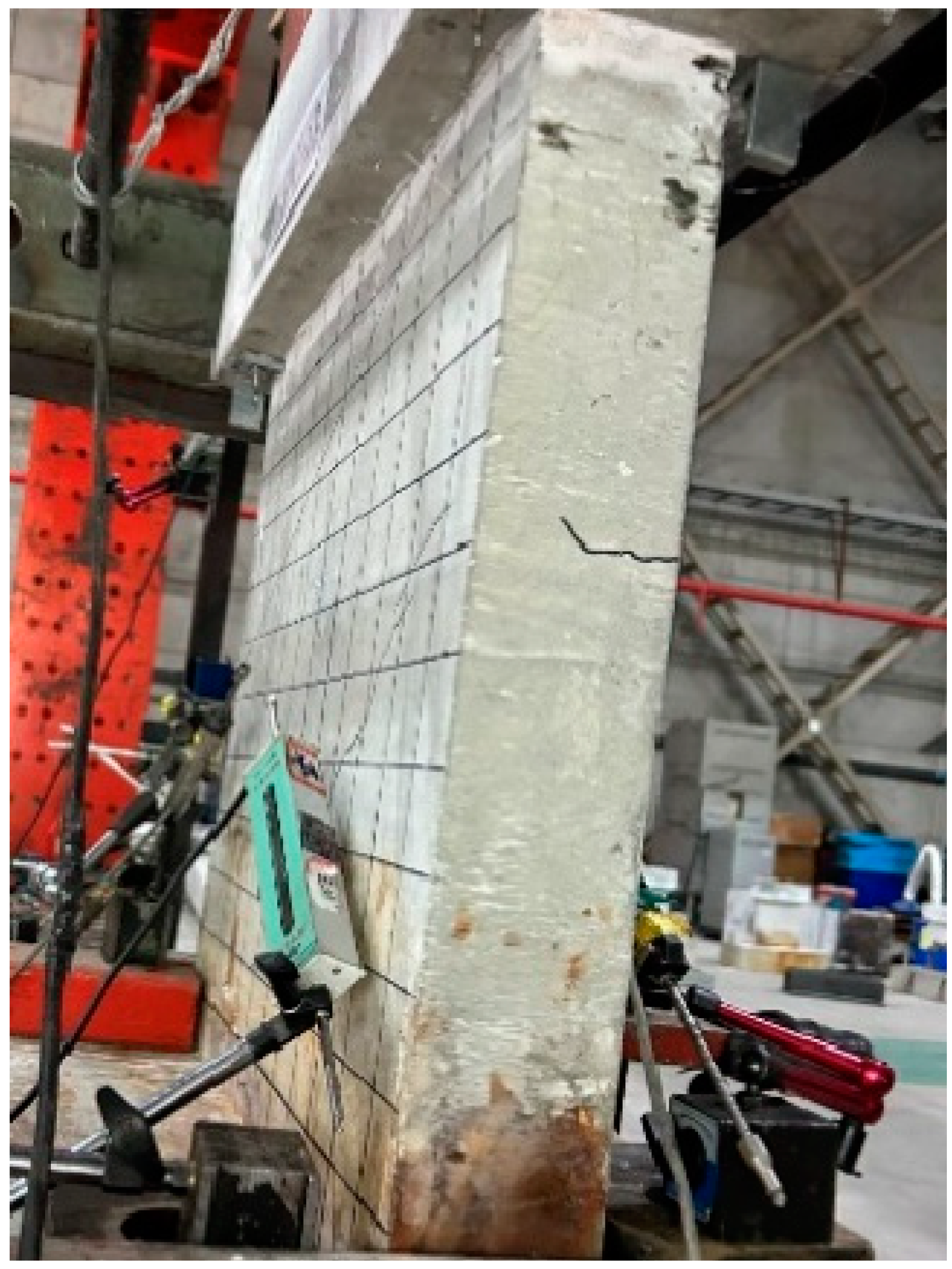
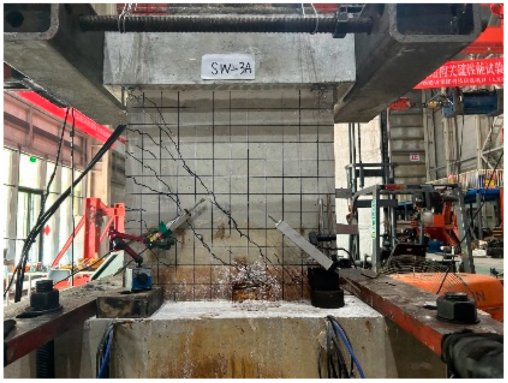
3.2. Analysis of the Loading Failure

For SW-1, when the horizontal displacement was below 1.05 mm, no significant change occurred. When the displacement on the surface of SW-1B increased to 1.4 mm, the first inclined crack developed, as shown in Figure 18. However, no crack developed on the surface of SW-1A. This was due to the local corrosion occurring on the SW-1B surface but not on the SW-1A surface, indicating a different degree of corrosion on the A and B sides of SW-1. This led to the crack appearing at different times despite the reinforcement and material being the same on both sides. The crack appeared early on the surface of SW-1B, which may be due to the relatively intact nature of the concrete cover on this side. Under the action of the load, the weak concrete cover cracked easily. The corrosion of the surface of SW-1A was more serious, and the CICs were more abundant. What’s more, under loading conditions, the small CICs slightly widened or lengthened. Since the phenomenon was not obvious, it is believed that no new cracks developed at that time. When the horizontal displacement increased to 2.1 mm, the first inclined crack developed on the surface of SW-1A. At this time, the second inclined crack, parallel to the first one, developed on the surface of SW-1B. Five horizontal cracks on the edge of the tension side of the SRCSWs also developed, almost penetrating all the way through. Since then, cracks increased with the increase in the load. The phenomena on the surface of SW-1A and SW-1B were getting closer. The expansion of the cracking area was approximately synchronous. When the horizontal displacement increased to 5.6 mm, the concrete at the location of the inclined cracks on the surface of SW-1B began to flake. As the horizontal displacement increased to 7.0 mm, the concrete at the lower left corner was crushed and the spalling trend appeared. The loading ended when the horizontal load became lower than 85% of the peak value. At that point, the test was terminated. The failure mode of SW-1 was shear failure.
For SW-2, when the horizontal displacement was below 1.05 mm, the specimen exhibited no significant change. When the displacement increased to 1.4 mm, the first crack developed on the surfaces of both SW-2A and SW-2B, as shown in Figure 19. Meanwhile, small cracks developed on the side of the wall, as depicted in Figure 20. As the horizontal displacement increased to 2.1 mm, the cracks extended to both ends of the first crack. No new cracks developed on SW-2A, while a second and third crack developed on SW-2B. The circumstances were similar to those surrounding the appearance of the first crack on SW-1, that is, the concrete on the lighter side of the corrosion needed to crack earlier to resist external forces. This also explains the different bearing capacity on both sides of the structure. As the horizontal displacement increased, the cracks widened gradually. When the horizontal displacement reached 9.8 mm, the concrete at the bottom of both sides of the wall became crushed. Then, the failure load was reached when the horizontal displacement reached 10.5 mm. The loading of SW-2 was terminated, and the failure mode of SW-2 was shear failure.
For SW-3, when the horizontal displacement was below 1.05 mm, the specimen exhibited no significant change. When the displacement increased to 1.05 mm, the first crack developed on the surfaces of both SW-3A and SW-3B, as shown in Figure 21, and tiny cracks also appeared. The first crack on SW-3 appeared earlier than those on SW-1 and SW-2, a phenomenon which indicates that the crack developed early when the specimen was seriously corroded and the bearing capacity of the SRCSW was greatly influenced by the corrosion. When the horizontal displacement increased to 2.1 mm, a horizontal crack developed at the bottom of the side presenting the corroded area. When the horizontal displacement increased to 7.0 mm, the width of the maximum inclined crack reached 1.5 mm. When the horizontal displacement increased to 9.8 mm, part of the concrete spalled on the side, and the width of the inclined crack reached 4 mm. The horizontal displacement continued to increase, until the structure failed. The failure mode of SW-3 was shear failure, as shown in Figure 22.

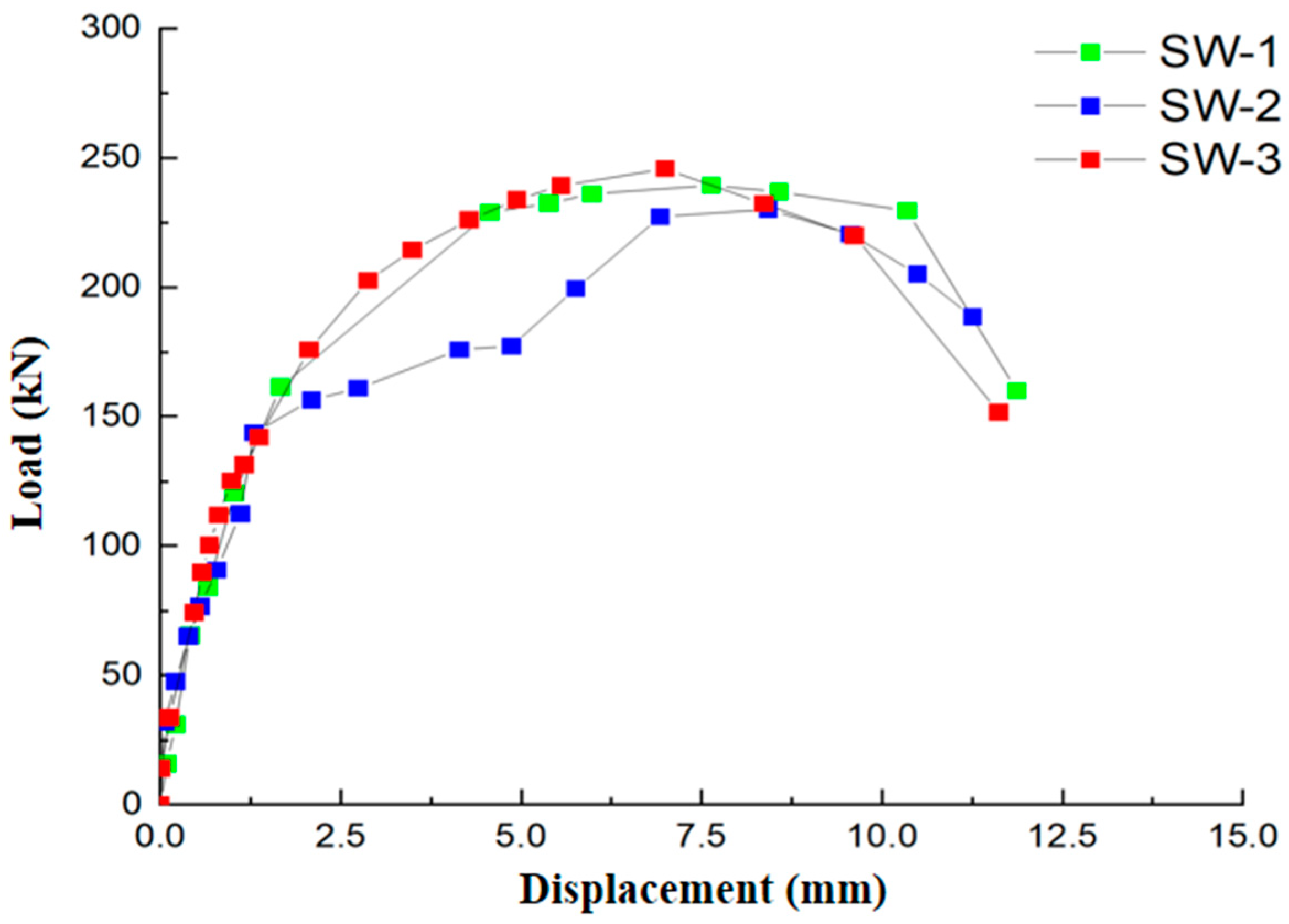
3.3. Load–Displacement Curves of Corroded SRCSWs

The load–displacement curves of the specimens are illustrated in Figure 23. The test values of the characteristic points are listed in Table 2. The cracking load (Pc) was determined by the appearance of the first crack during the test. Nowadays, the commonly used calculation methods of yield load (Py) and yield displacement (Δy) include the energy equivalent method, the R. Park method, and the general yield moment method [9,51,52]. This paper adopts the general yield moment method to calculate the yield load and yield displacement of SRCSWs. The ultimate displacement (Δu) was determined by the displacement corresponding to the moment when the horizontal load decreased to 85% of the peak load (Pm).
The load–displacement curves of SW-1, SW-2, and SW-3 were compared, and the results show that the continuous increase in horizontal displacement also increased the load. Figure 23 shows that, before the load reached about 150 kN, the load–displacement curves of the three specimens were basically identical, and all of them were linear. This was because no specimen had reached the yield point and was still in the elastic stage. When the horizontal displacement continued to increase, the load–displacement curve of SW-2 began to shift significantly, and the slope of the curve decreased significantly. When the horizontal displacement reached 1.44 mm, the SW-2 yielded, and the yield load was 145.89 kN. As the loading continued, the load–displacement curves of SW-1 and SW-3 continued to be linear. However, soon after, the slope of the curves dropped significantly. When the horizontal displacement reached 1.73 mm, the SW-3 yielded, and, shortly thereafter, the SW-1 also reached the yield. Compared to SW-1, the peak load of the SW-2 decreased by 4.0%, while that of SW-3 increased by 2.7%. Compared to SW-1, the yield loads of SW-2 and SW-3 decreased by 22.4% and 11.8%, respectively. The corrosion test results indicate that the corrosion degree of SW-2 was the greatest and that SW-1 was the lightest among the three SRCSWs. This may be because of the uneven construction of the SRCSWs and the relatively great inhomogeneity of the concrete, leading to more internal pores and to the poor resistance to chloride ion penetration of the walls. Compared to SW-1 and SW-3, the yield, peak, and ultimate loads of SW-2 were the smallest. This is because the larger the MLTSB inside the base of the structure, the more microcracks were formed by steel corrosion inside the base of the shear wall, and the more obvious the stress concentration phenomenon inside the base—the corroded area along the base was an obvious local defect of the shear wall—and, as a result, in the interior of the SW-2 with the largest corrosion degree, the more prone the structure to local damage under external loads, leading to the bearing capacity of SW-2 being the smallest.

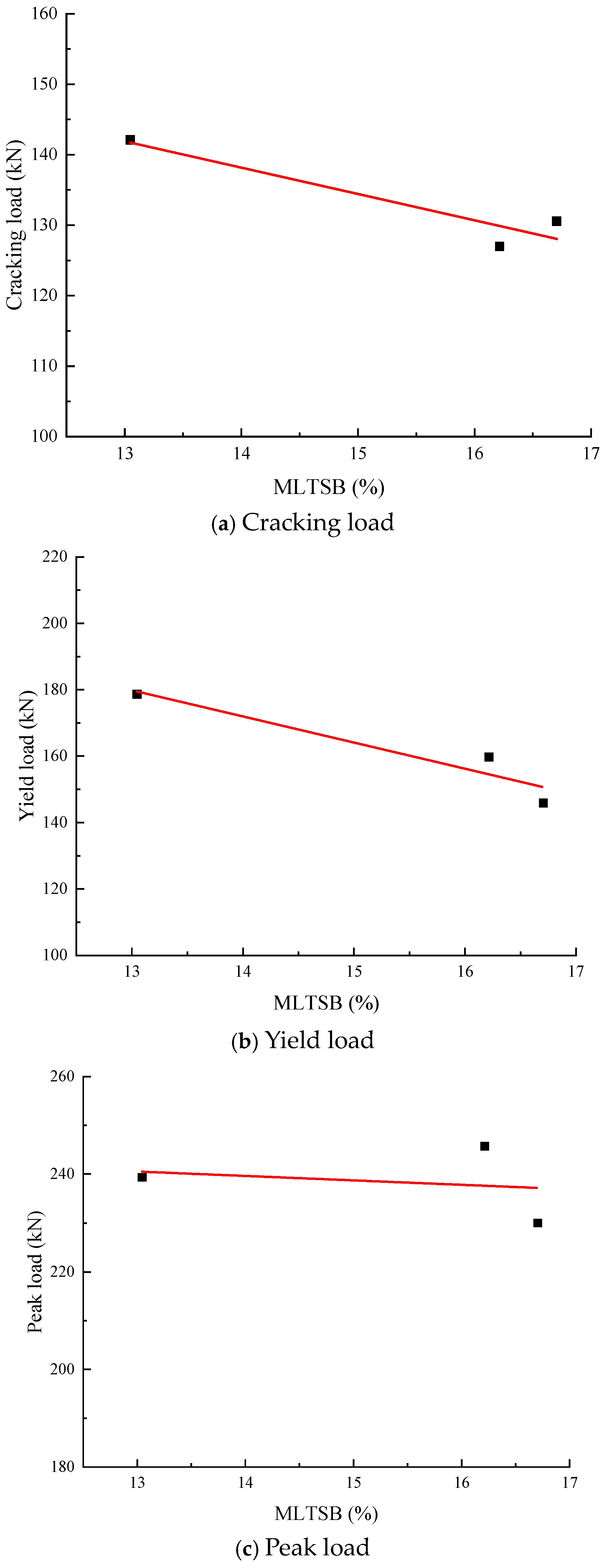
3.4. Relationship Between the Mechanical Properties of the Corroded SRCSWs and the MLTSB

The cracking, yield, and peak loads of the specimens are shown in Table 2. In order to better obtain the impact of the mass loss of steel bars on the mechanical properties of SRCSWs, a detailed analysis was conducted investigating the relationships between the MLTSB and the cracking, yield, and peak loads. Specifically, the test data of SW-1, SW-2, and SW-3 were used to analyze the variation trends in MLTSB with cracking load, yield load, and peak load, respectively. The relevant analysis results are shown in Figure 24, which indicates that the mechanical properties of SRCSWs were directly affected by the corrosion degree of the steel bars inside the base. In addition, the cracking, yield, and peak loads decreased with the increase in MLTSB. As the MLTSB increased from 13.05% to 16.71%, the crack, yield, and peak loads decreased by 8.8%, 22.4%, and 6.8%, respectively. The crack, yield, and peak loads exhibited an approximately linear relationship with the MLTSB, and the corresponding fitting relations are shown in Equations (2)–(4) (R2 = 0.88, 0.91, and 0.85), respectively. As the degree of steel corrosion intensified inside the base of the walls, the corrosion products produced by the steel bars increased, more CICs developed, induced by the products, inside the base of the SRCSWs, and, as a result, the overall performance of the concrete at the base weakened, causing the SRCSWs to crack more easily under loading conditions. When loading began, the SRCSW with a high damage degree at the base cracked first. The greater the degree of steel corrosion, the smaller the cross-sectional area of the steel bars inside the SRCSWs, and the more severe the reduction of the yield strength of steel bars [53,54,55]. Moreover, when the mass loss of the steel bars extended beyond a critical value, the greater the degree of steel corrosion, the more severe the degradation of the bond performance between the steel bars and the concrete [56,57,58] inside the base, in turn affecting the bearing capacity of the SRCSWs corroded at the base. Under external loads, the steel bars that were severely corroded inside the base of the SRCSWs reached the yield first, while the steel bars at other locations within the SRCSWs were still in the elastic stage. Then, the concrete in the compression zone at the base became crashed, and, finally, the entire SRCSW yielded at the base.
The fitting formula for the relationship between the cracking load and the MLTSB is as follows:
P c = 190.47 3.74 η ( 13.05 η 16.71 )
where η is the MLTSB in the corroded area of the SRCSWs (%).
The fitting formula for the relationship between the yield load and the MLTSB is as follows:
P y = 282.08 7.87 η ( 13.05 η 16.71 )
The fitting formula for the relationship between the peak load and the MLTSB is as follows:
P m = 252.28 0.91 η ( 13.05 η 16.71 )

3.5. Relationship Between the Mechanical Properties of Corroded SRCSWs and the Average Width of CICs

The average width of CICs was obtained by using the width of CICs at the front and back of the corroded SRCSWs, reflecting the damage degree of SRCSWs that was caused by the expansion of the corrosion products. The relationships between the average width of CICs and the cracking, yield, and peak loads were analyzed, respectively, as shown in Figure 25. It can be observed from Figure 25 that the crack, yield, and peak loads decreased with the increase in the average width of CICs. When the average width of CICs increased from 0.24 mm to 0.40 mm, the crack, yield, and peak loads decreased by 8.8%, 22.4%, and 6.8%, respectively. Also, the crack, yield, and peak loads were linearly correlated with the average width of CICs, and the corresponding fitting relations are shown in Equations (5)–(7) (R2 = 0.96, 0.87, and 0.83), respectively. The larger the average width of the CICs, the more severe the corrosion of the steel bars in the shear walls. Thus, the SRCSWs were easier to crack and yield under loading conditions. With the increase in the average width of CICs, the degree of corrosion of the walls increased and the bond damage between the steel bars and the concrete also increased, affecting their joint work. In addition, with the increase in the degree of corrosion, the effective cross-section of the steel bars decreased and the mechanical properties weakened. Furthermore, the mechanical properties of the concrete could also be affected by the corrosion of the steel bars. Under the effects of these factors, a decreasing trend in the crack, yield, and peak loads of the walls was observed with the increase in the average width of CICs.
The fitting formula for the relationship between the cracking load and the average width of CICs is as follows:
P c = 162.64 86.30 W mean ( 0.24 W mean 0.40 )
where Wmean is the average width of CICs in the corroded area of the wall (mm).
The fitting formula for the relationship between the yield load and the average width of CICs is as follows:
P y = 217.28 163.88 W mean ( 0.24 W mean 0.40 )
The fitting formula for the relationship between the peak load and the average width of CICs is as follows:
P m = 240.76 7.07 W mean ( 0.24 W mean 0.40 )
It should be pointed out that the above six formulas were only obtained by fitting a small amount of experimental data, and further verification of their rationality would require a large amount of experimental or measured data.

4. Conclusions

The mechanical properties of SRCSWs with corrosion along the base are assessed through the accelerated corrosion test and the loading failure test in this study, and the main conclusions are as follows:
(1)
With an increase in corrosion time, the corrosion-induced cracking area on the SRCSWs increases. When the corrosion time is the same for two investigated structures, the corrosion-induced cracking area on these is approximately equal between the two. The loading failure laws for SRCSWs presenting different corrosion degrees along the base are obviously different. However, the failure mode is always shear failure.
(2)
The load–displacement curves of SRCSWs with different degrees of corrosion are basically identical and are linear when the loading is in the elastic stage. Compared to the SW-1, the peak load of SW-2 decreases by 4.0%, while that of SW-3 increases by 2.7%.
(3)
As the MLTSB increases from 13.05% to 16.71%, the crack, yield, and peak loads decrease by 8.8%, 22.4%, and 6.8%, respectively. All of them show an approximately linear relationship with the MLTSB, respectively, and the corresponding fitting relations are established.
(4)
When the average width of CICs increases from 0.24 mm to 0.40 mm, the crack, yield, and peak loads decrease by 8.8%, 22.4%, and 6.8%, respectively. The crack, yield, and peak loads of SRCSWs with corrosion along the base decrease linearly with the increase in the average width of CICs, and the corresponding fitting relations are established.
(5)
The fitting formulas presented in this paper are obtained from a small subset of test results, and, in future research, more SRCSWs with corrosion along the base should be constructed and tested to modify the fitting formulas. Moreover, the seismic properties of SRCSWs with corrosion along the base are not studied in this paper, offering an opportunity for further research.

Author Contributions

Y.W.: investigation, formal analysis, writing—original draft. Z.B.: data curation, writing—original draft, writing—review and editing. S.L.: data curation, writing—review and editing. J.W.: conceptualization, methodology, writing—review and editing, project administration, funding acquisition, resources, supervision. All authors have read and agreed to the published version of the manuscript.

Funding

This research was funded by the Central Research and Development Project of China National Nuclear Corporation (No. ZHJTJZYFWD2020) and by the project of structural performance evaluation and life prediction model under typical conditions (No. HT-99982023-0366).

Data Availability Statement

The data presented in this study are available upon request from the corresponding author.

Conflicts of Interest

Authors Yougang Wang, Zhengchao Bi and Sheng Luo were employed by the company China Nuclear Power Technology Co., Ltd. The remaining authors declare that the research was conducted in the absence of any commercial or financial relationships that could be construed as a potential conflict of interest.

References

  1. Liu, H.; Shi, N.; Han, K.; Fu, X.; Fang, Y. Study on the attack of concrete by external sulfate under electric fields. Coatings 2024, 14, 1008. [Google Scholar] [CrossRef]
  2. Han, M.; Li, J. Enhancement of compressive strength and durability of sulfate-attacked concrete. Buildings 2024, 14, 2187. [Google Scholar] [CrossRef]
  3. Yuan, W.; Wang, Y.; Zhou, Y.; Yuan, W.; Yao, Y. Effect of biaxial loading path on seismic performance of RC bridge piers with corrosion damage. KSCE J. Civ. Eng. 2023, 27, 5243–5255. [Google Scholar] [CrossRef]
  4. Li, M.; Shen, D.; Yang, Q.; Cao, X.; Huang, C.; Cui, Z.; Qi, Y. Effect of reinforcement corrosion on the seismic performance of reinforced concrete shear walls. Constr. Build. Mater. 2023, 377, 130977. [Google Scholar] [CrossRef]
  5. Zheng, S.; Zhou, Y.; Li, Q.; Long, L.; Dong, L.; He, J. Experimental study on aseismic behavior of squat RC shear walls due to chloride ion erosion. Eng. Mech. 2019, 36, 69–78. [Google Scholar]
  6. Gao, X.; Xu, Z.; Ren, X.; Li, L. Experimental analysis of RC and SPRC squat shear walls. J. Build. Struct. 2024, 93, 109861. [Google Scholar] [CrossRef]
  7. Long, H.; Chen, L.; Dong, B.; Sun, Y.; Yan, Y.; Chen, C. The electronic properties and surface chemistry of passive film on reinforcement: Effect of composition of simulated concrete pore solution. Constr. Build. Mater. 2022, 360, 129567. [Google Scholar] [CrossRef]
  8. Mandal, S.; Singh, J.K.; Mallapur, S.; Lee, D.; Park, T. Effect of triethanolamine and sodium hexametaphosphate on formation, growth and breakdown of passive layer in concrete pore solution. J. Build. Eng. 2022, 59, 105113. [Google Scholar] [CrossRef]
  9. Wang, X.; Ba, M.; Yi, B.; Liu, J. Experimental and numerical investigation on the effect of cracks on chloride diffusion and steel corrosion in concrete. J. Build. Struct. 2024, 86, 108521. [Google Scholar] [CrossRef]
  10. Liu, Y.; Miao, Z.; Hogan, L.; Zhu, M.; Lu, Y. A new prediction model for residual deformation capacity of corroded steel bars. Eng. Struct. 2024, 318, 118739. [Google Scholar] [CrossRef]
  11. Qiu, W.; Peng, R.; Jiang, M. Investigation on the prediction of reinforcement corrosion-induced cover time-vary cracking from multi-scale. Structures 2022, 43, 1305–1314. [Google Scholar] [CrossRef]
  12. Chen, W.; Xu, S.; Zhang, W.; Ma, Z.; Zhang, J.; Zhang, Y.; Zhang, Y. Effect of bidirectional electromigration rehabilitation on corroded reinforcement and surrounding concrete in chloride contaminated concrete. J. Build. Struct. 2024, 93, 109840. [Google Scholar] [CrossRef]
  13. Dang, V.H.; François, R. Influence of long-term corrosion in chloride environment on mechanical behaviour of RC beam. Eng. Struct. 2013, 48, 558–568. [Google Scholar] [CrossRef]
  14. Zhang, R.; Castel, A.; François, R. The corrosion pattern of reinforcement and its influence on serviceability of reinforced concrete members in chloride environment. Cem. Concr. Res. 2009, 39, 1077–1086. [Google Scholar] [CrossRef]
  15. Li, L.; Liu, W.; Zhou, C.; Zeng, Q. Probabilistic assessment of silane impregnation and electrochemical chloride removal treatment on protection effect against steel corrosion in marine concrete structures. Dev. Built Environ. 2024, 17, 100364. [Google Scholar] [CrossRef]
  16. Yang, L.; Zheng, S.; Zheng, Y.; Dong, L.; Wu, H. Experimental investigation and numerical modelling of the seismic performance of corroded T-shaped reinforced concrete shear walls. Eng. Struct. 2023, 283, 115930. [Google Scholar] [CrossRef]
  17. Tang, Z.; Zhang, C. Effects of corrosion and pre-fatigue damage on the mechanical properties of HRB400E rebars. J. Constr. Steel Res. 2024, 217, 108641. [Google Scholar] [CrossRef]
  18. Ren, S.; Gu, Y.; Gao, X.; Gu, S.; Kong, C.; Zeng, S.; Liu, P.; Li, X. Estimating the effects of corrosion pitting morphology on residual fatigue properties of corroded steel based on fractal theory. Int. J. Steel Struct. 2023, 23, 480–492. [Google Scholar]
  19. Zhou, B.; Wang, H.; Yu, J.; Sun, X. Performance degradation of steel rebar considering corrosion spatial variability in concrete. Constr. Build. Mater. 2024, 411, 134783. [Google Scholar] [CrossRef]
  20. Zhang, X.; Zheng, S.; Ruan, S.; Hu, J.; Li, Y. Research on seismic performance test and numerical simulation of corroded L-shaped RC shear wall. Eng. Mech. 2024, 40, 213–224. [Google Scholar]
  21. Zheng, Y.; Kang, X.; Zheng, S.; Zhang, Y.; Liu, X. Study on seismic behavior of corroded reinforced concrete walls in flexural-shear failure. Structures 2024, 67, 107003. [Google Scholar] [CrossRef]
  22. Yalciner, H.; Kumbasaroglu, A. Experimental study to predict bond-slip behavior of corroded reinforced concrete columns. ACI Struct. J. 2022, 119, 111–128. [Google Scholar]
  23. Yang, B.; Hu, X.; Qiao, H. Enhancing durability of concrete in saline soil with nano-CaCO3 modification: Investigation and reliability analysis. KSCE J. Civ. Eng. 2024, 28, 3791–3804. [Google Scholar] [CrossRef]
  24. Ding, F. Mechanical Properties Research of Non-Uniform Corroded Reinforced Concrete Shear Wall Based on UMAT. Master’s Thesis, Xi’an University of Architecture and Technology, Xi’an, China, 2017. [Google Scholar]
  25. Dong, Y. Research on Seismic Behavior of Uniform Corroded Reinforced Concrete Shear Wall Based on ABAQUS. Master’s Thesis, Xi’an University of Architecture and Technology, Xi’an, China, 2016. [Google Scholar]
  26. Guo, J. Experimental Study and Finite Element Analysis on the Seismic Behavior of Squat Recycled Concrete Shear Walls. Master’s Thesis, Beijing University of Civil Engineering and Architecture, Beijing, China, 2015. [Google Scholar]
  27. Farzinpour, A.; Dehcheshmeh, E.M.; Broujerdian, V.; Esfahani, S.N.; Gandomi, A.H. Efficient boosting-based algorithms for shear strength prediction of squat RC walls. Case Stud. Constr. Mater. 2023, 13, e01928. [Google Scholar] [CrossRef]
  28. Gan, C. Experimental Research on Seismic Behaviors of Squat RC Shear Walls Subjected to Freeze-Thaw Cycles. Master’s Thesis, Xi’an University of Architecture and Technology, Xi’an, China, 2016. [Google Scholar]
  29. Zheng, S.; Sang, Z.; Zhou, Y. Seismic test and shear strength prediction of squat RC shear walls under acidic environment. Eng. Mech. 2023, 40, 213–224. [Google Scholar]
  30. Devine, R.D.; Barbachyn, S.M.; Thrall, A.P.; Kurama, Y.C. Effect of aspect ratio, flanges, and material strength on squat reinforced concrete shear walls. ACI Struct. J. 2020, 117, 283–300. [Google Scholar]
  31. Miao, L.; Jin, L.; Chen, F.; Du, X. Experiment study on seismic performance and size effect in BFRP-RC squat shear walls with different horizontal reinforcement ratios. Eng. Struct. 2023, 295, 116888. [Google Scholar] [CrossRef]
  32. Rao, G. The Nonlinear Analysis and Performance Research of Low-Rise RC Shear Wall. Master’s Thesis, Hunan University, Changsha, China, 2005. [Google Scholar]
  33. Shao, W.; Qian, G.; Tong, Y. Research on Reinforced Concrete Squat Shear Walls. J. Xi’an Inst. Metall. Constr. Eng. 1989, 21, 15–23. [Google Scholar]
  34. Guo, Z.; Tong, Y.; Qian, G. Study on the deformation behaviour and restoring force model of squat shear wall. J. Xi’an Univ. Arch. Technol. 1998, 30, 25–28. [Google Scholar]
  35. Liu, B.; Guo, Z.; Huang, Q. A practical calculating method for evaluating the shear capacity and lateral stiffness of RC squat shear walls with boundary frame. Sichuan Build. Sci. 2009, 35, 141–144. [Google Scholar]
  36. Thomson, E.D.; Perdomo, M.E.; Picón, R.; Marante, M.E.; Flórez-López, J. Simplified model for damage in squat RC shear walls. Eng. Struct. 2009, 31, 2215–2223. [Google Scholar] [CrossRef]
  37. Salonikios, T.N. Shear strength and deformation patterns of R/C walls with aspect ratio 1.0 and 1.5 designed to Eurocode 8 (EC8). Eng. Struct. 2002, 24, 39–49. [Google Scholar] [CrossRef]
  38. Massone, L.M. Strength prediction of squat structural walls via calibration of a shear-flexure interaction model. Eng. Struct. 2010, 32, 922–932. [Google Scholar] [CrossRef]
  39. Zheng, S.; Li, Q.; Qin, Q.; Zuo, H.; Dong, L.; Liu, W. Experimental study on seismic behaviors of corroded squat reinforced concrete shear walls. J. Build. Struct. 2019, 40, 79–87. [Google Scholar]
  40. Zheng, S.; Qin, Q.; Yang, W.; Gan, C.; Zhang, Y.; Ding, S. Experimental research on the seismic behaviors of squat RC shear walls under offshore atmospheric environment. J. Harbin Inst. Technol. 2015, 47, 64–69. [Google Scholar]
  41. GB 50010; Code for Design of Concrete Structure. China Architecture & Building Press: Beijing, China, 2015.
  42. JGJ 55; Specification for Mix Proportion Design of Ordinary Concrete. China Architecture & Building Press: Beijing, China, 2011.
  43. GB 50081; Standard for Test Methods of Concrete Physical and Mechanical Properties. China Architecture & Building Press: Beijing, China, 2019.
  44. Law, D.W.; Tang, D.; Molyneaux, T.K.C. Impact of crack width on bond, confined and unconfined rebar. Mater. Struct. 2011, 44, 1287–1296. [Google Scholar] [CrossRef]
  45. Malumbela, G.; Alexander, M.; Moyo, P. Interaction between corrosion crack width and steel loss in RC beams corroded under load. Cem. Concr. Res. 2010, 40, 1419–1428. [Google Scholar] [CrossRef]
  46. Maaddawy, T.A.E.I.; Soudki, K.A. Effectiveness of impressed current technique to simulate corrosion of steel reinforcement in concrete. J. Mater. Civ. Eng. 2003, 15, 41–47. [Google Scholar] [CrossRef]
  47. GB 50152; Standard Methods for Testing of Concrete Structures. China Architecture & Building Press: Beijing, China, 1992.
  48. GB/T 50082; Standard for Test Methods of Long-Term Performance and Durability of Ordinary Concrete. China Architecture & Building Press: Beijing, China, 2009.
  49. Chen, M.; Liu, X.; Mei, K.; Wang, S.; Liu, J.; Li, Y. Corrosion behavior of steel bar in magnesium oxysulfide cement-based materials: The role of chloride and nitrite. J. Mater. Res. Technol. 2024, 32, 1577–1588. [Google Scholar] [CrossRef]
  50. Wang, J.; Yuan, Y.; Song, Y.; Wang, Z.; Du, J.; Su, H. Cracking characteristics and axial capacity degradation of precast segmental bridge piers connected with corroded tapered sleeve locking-type splicing. Structures 2024, 65, 106740. [Google Scholar] [CrossRef]
  51. Qing, Q. Experimental Studies on Seismic Behavior of Corroded Squat RC Shear Walls Under Artificial Climate Environment. Master’s Thesis, Xi’an University of Architecture and Technology, Xi’an, China, 2014. [Google Scholar]
  52. Hao, C. Research on Seismic Performance of Self-Centering Mortise-Tenon Segmental Pier Based on Cyclic Pseudo-Static Test. Master’s Thesis, Beijing Jiaotong University, Beijing, China, 2022. [Google Scholar]
  53. Wang, F.; Xue, X.; Hua, J.; Chen, Z.; Huang, L.; Wang, N.; Jin, J. Non-uniform corrosion influences on mechanical performances of stainless-clad bimetallic steel bars. Mar. Struct. 2022, 86, 103276. [Google Scholar] [CrossRef]
  54. Papadopoulos, M.P.; Apostolopoulos, C.A.; Alexopoulos, N.D.; Pantelakis, S.G. Effect of salt spray corrosion exposure on the mechanical performance of different technical class reinforcing steel bars. Mater. Des. 2007, 28, 2318–2328. [Google Scholar] [CrossRef]
  55. Li, Y.; Zheng, S.; Dong, L.; Wang, D.; Sang, Z.; Wen, G. Mechanical properties of corroded steel bars on the tensile and buckling considering stirrup constraints. Constr. Build. Mater. 2024, 417, 135181. [Google Scholar] [CrossRef]
  56. Chai, X.; Shang, H.S.; Zhang, C.W. Bond behavior between corroded steel bar and concrete under sustained load. Constr. Build. Mater. 2021, 310, 125122. [Google Scholar] [CrossRef]
  57. Shang, H.S.; Zhou, J.H.; Yang, G.T. Study on the bond behavior of corroded steel bars embedded in concrete under the coupled effect of reciprocating loads and chloride ion erosion. Constr. Build. Mater. 2021, 305, 124658. [Google Scholar] [CrossRef]
  58. Liu, T.; Xu, Z.; Huang, T.; Yang, J.; Huang, Y.; Xu, N.; Pan, C.; Hua, L.; Li, J. Experimental research on the degradation law of the bond performance between steel bars and concrete with rust expansion cracking. Constr. Build. Mater. 2024, 450, 138544. [Google Scholar] [CrossRef]
Figure 1. Dimensions and reinforcement of the SRCSW specimens (unit: mm). (a) Front view; (b) 1-1; (c) 2-2; (d) 3-3; (e) 4-4.
Buildings 14 03409 g001
Figure 2. Arrangement of strain gauges of steel bars.
Buildings 14 03409 g002
Figure 3. The tying of the skeleton of the steel bars. (a) The tying of the steel bars of the bottom beam; (b) The tying of the steel bars of the wall; (c) The tying of the steel bars of the top beam.
Buildings 14 03409 g003
Figure 4. Pouring of the concrete.
Buildings 14 03409 g004
Figure 5. Schematic diagram of different corrosion conditions for SRCSW specimens.
Buildings 14 03409 g005
Figure 6. Schematic diagram of the electrochemical corrosion of the SRCSW specimens.
Buildings 14 03409 g006
Figure 7. Soaking in the NaCl solution.
Buildings 14 03409 g007
Figure 8. Corrosion conditions after 7 days of electrochemical corrosion.
Buildings 14 03409 g008
Figure 9. Loading device.
Buildings 14 03409 g009
Figure 10. Corroded steel skeleton.
Buildings 14 03409 g010
Figure 11. Steel bars after the corrosion products were removed.
Buildings 14 03409 g011
Figure 12. Bubbles near the copper rod.
Buildings 14 03409 g012
Figure 13. Local corrosion products on the surface of the wall.
Buildings 14 03409 g013
Figure 14. Corrosion products floating on the surface of the solution.
Buildings 14 03409 g014
Figure 15. Corrosion product precipitates at the bottom of the solution.
Buildings 14 03409 g015
Figure 16. Wall surface after removal of the tank.
Buildings 14 03409 g016
Figure 17. Distribution of corrosion products on the surface of the wall.
Buildings 14 03409 g017
Figure 18. The first crack on the surface of SW-1B.
Buildings 14 03409 g018
Figure 19. The first crack on the surface of SW-2A.
Buildings 14 03409 g019
Figure 20. The first crack on the side surface of SW-2.
Buildings 14 03409 g020
Figure 21. The first crack on the surface of SW-3A.
Buildings 14 03409 g021
Figure 22. Failure mode of SW-3A.
Buildings 14 03409 g022
Figure 23. Load–displacement curves.
Buildings 14 03409 g023
Figure 24. Relationship between the cracking load, yield load, and peak load on one side and the MLTSB on the other.
Buildings 14 03409 g024
Figure 25. Relationship between the cracking load, yield load, and peak load on one side and the average width of CICs on the other.
Buildings 14 03409 g025aBuildings 14 03409 g025b
Table 1. Corrosion conditions for SRCSW specimens.
Number Corrosion Time of the Front Side (A Side)Corrosion Time of the Back Side (B Side)
SW-170 days0 days
SW-270 days42 days
SW-370 days70 days
Table 2. Results of the characteristic points of the load–displacement curves.
NumberPc/kNΔy/mmPy/kNPm/kNΔu/mmPu/kN
SW-1142.122.40178.63239.3210.92203.42
SW-2130.571.44145.89230.0210.93195.52
SW-3127.001.73159.76245.699.94208.83
Disclaimer/Publisher’s Note: The statements, opinions and data contained in all publications are solely those of the individual author(s) and contributor(s) and not of MDPI and/or the editor(s). MDPI and/or the editor(s) disclaim responsibility for any injury to people or property resulting from any ideas, methods, instructions or products referred to in the content.

