


Automated PLC Code Generation for the Implementation of Mode-Based Control Algorithms in Buildings


Abstract
:1. Introduction
State of the Art
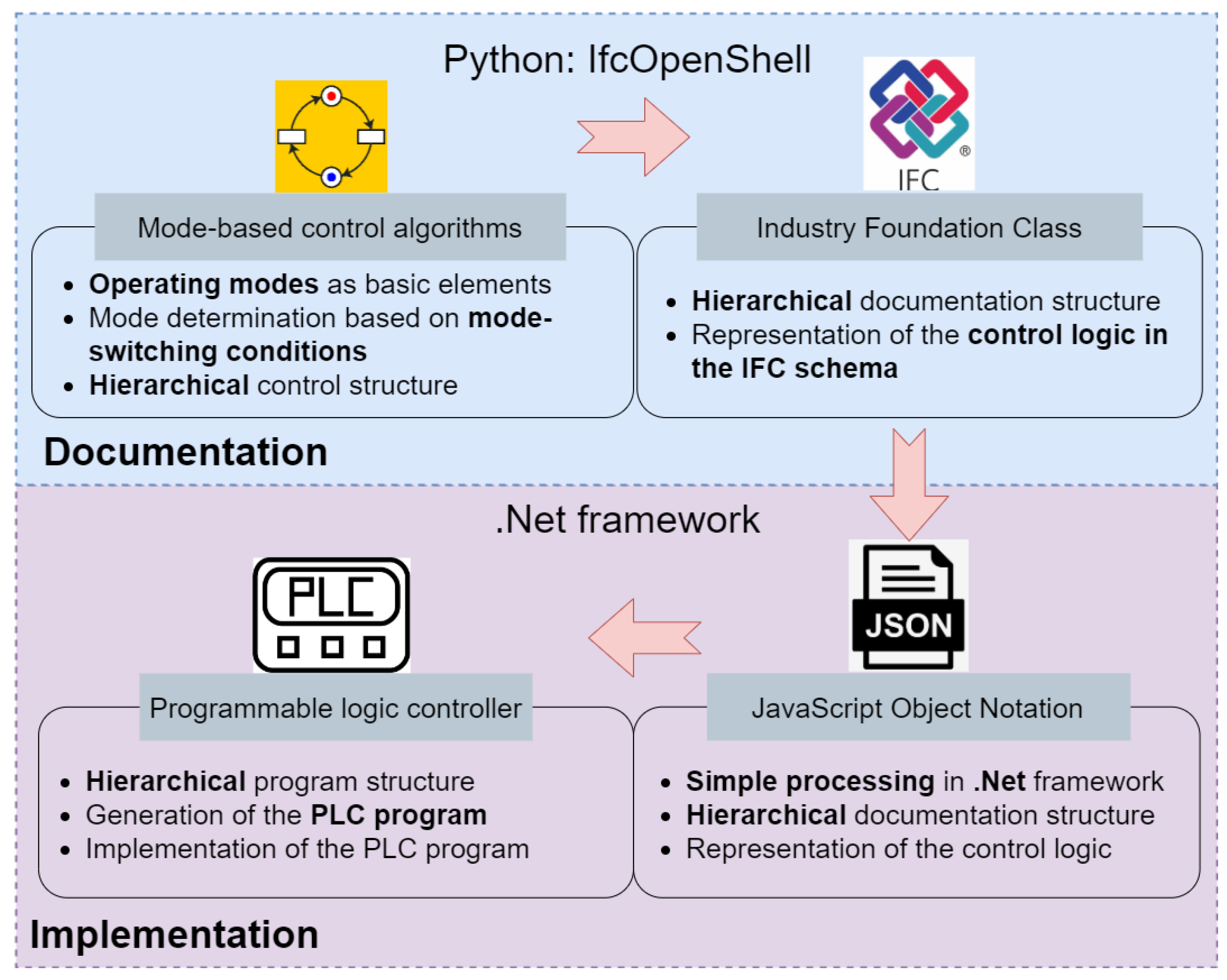
2. Methodology
2.1. Documentation of Mode-Based Control Algorithms in the IFC Schema
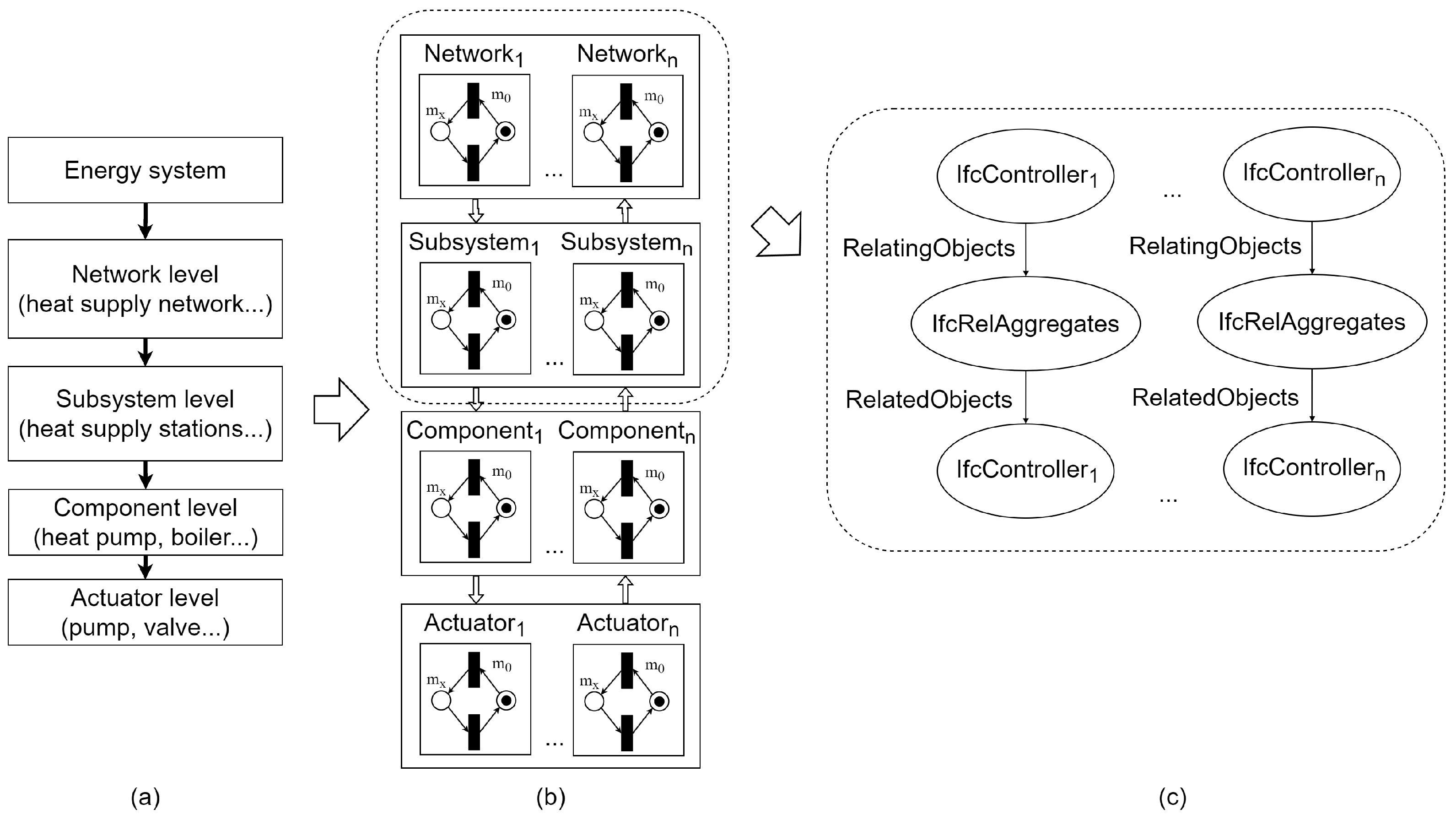
- Describe the hierarchical control structure of mode-based control algorithms in the IFC schema.
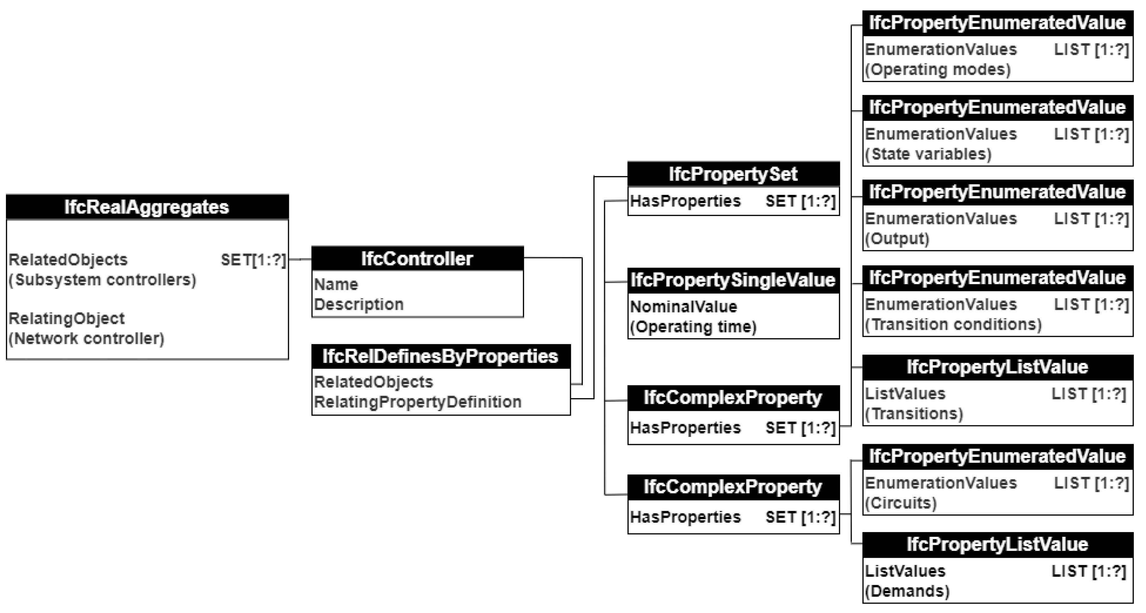
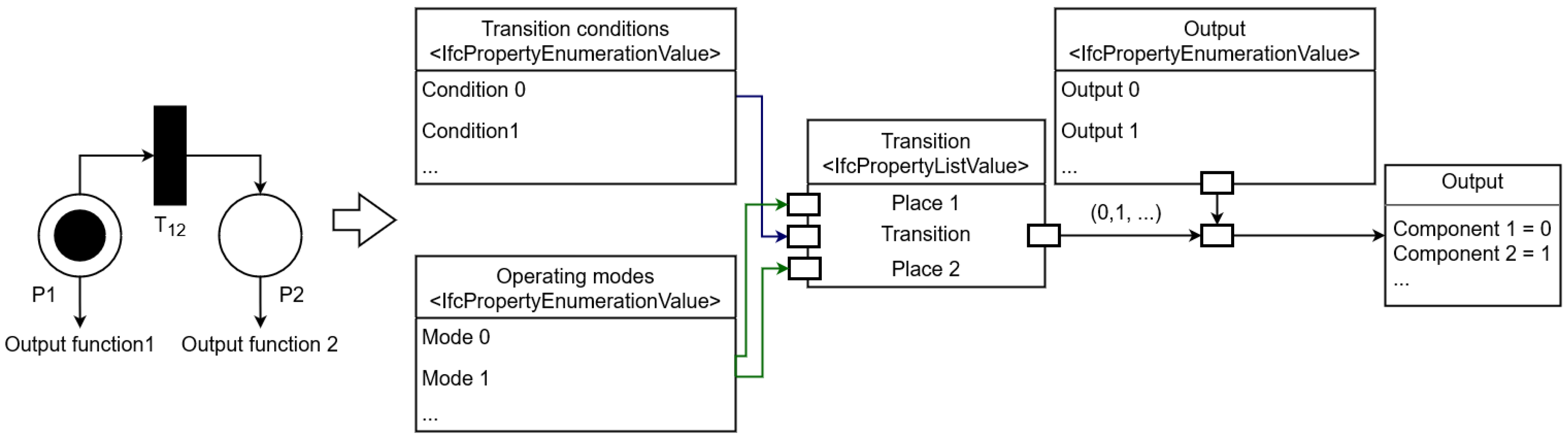
- Describe the SIPN-described control logic of mode-based control algorithms at each level in the IFC schema.
- Describe the connections between controllers and energy systems in the IFC schema.
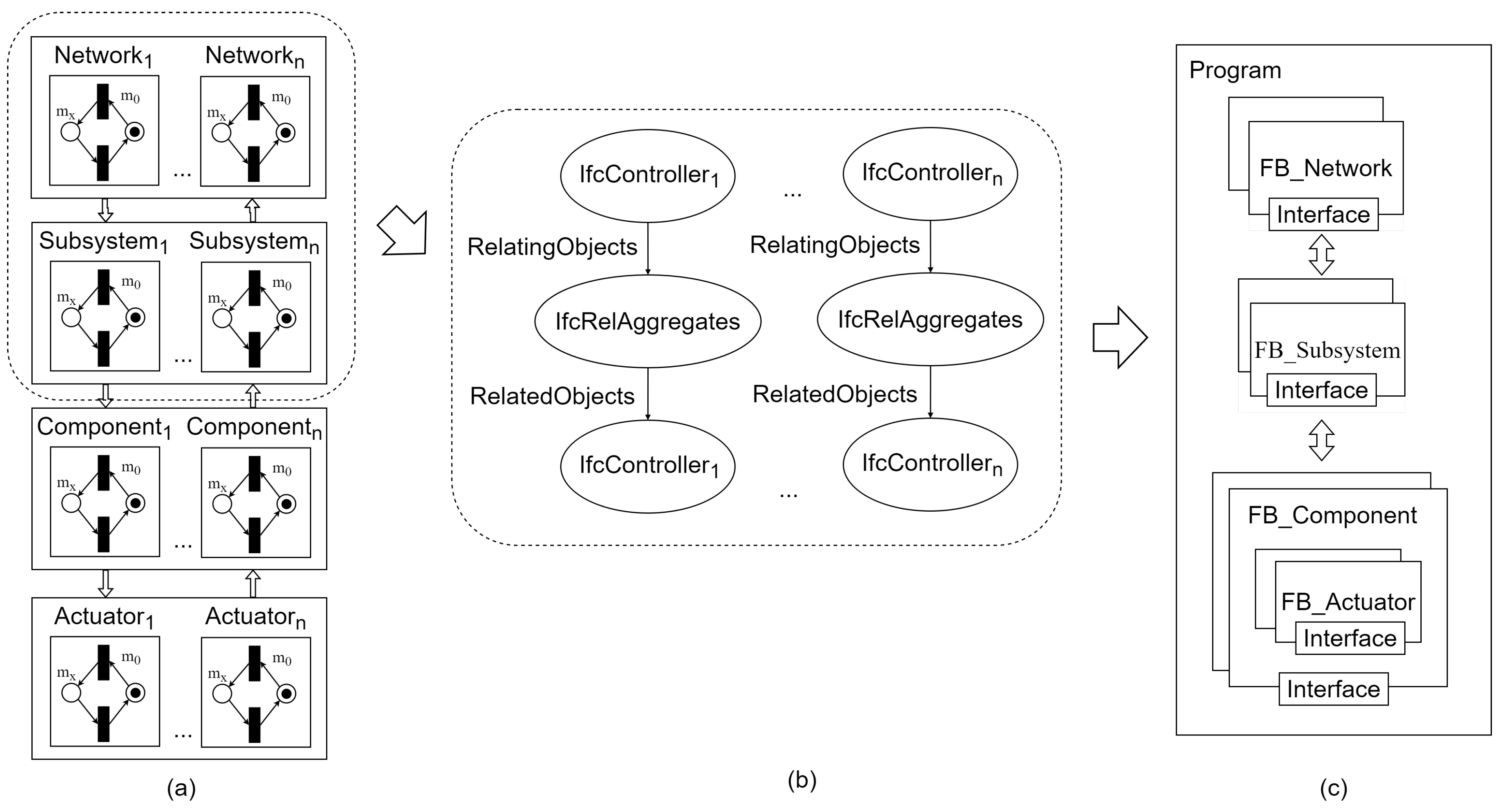
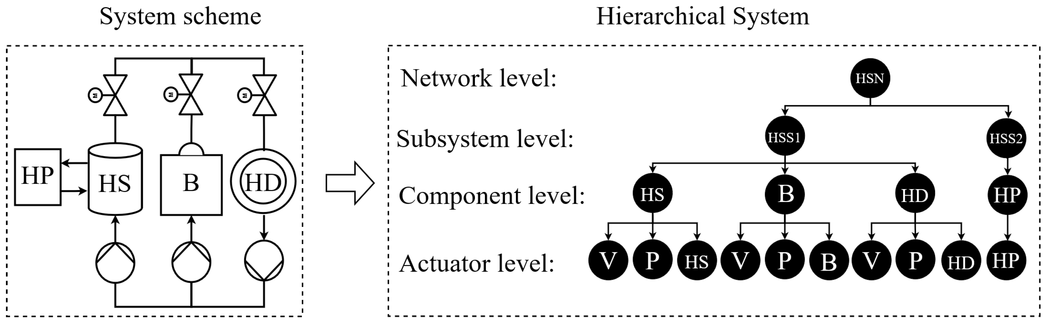
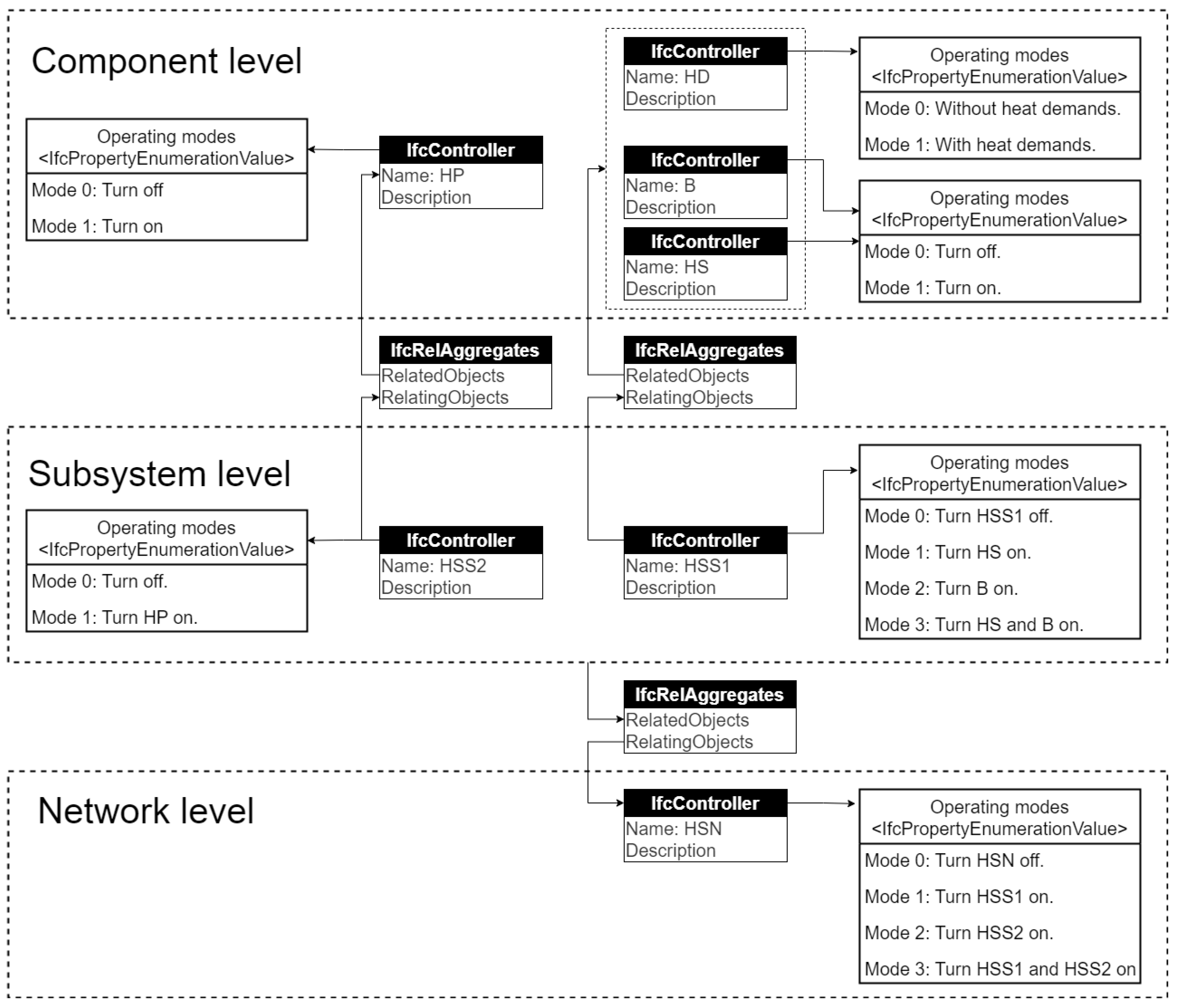
2.1.1. Hierarchical Control Structure in the IFC Schema
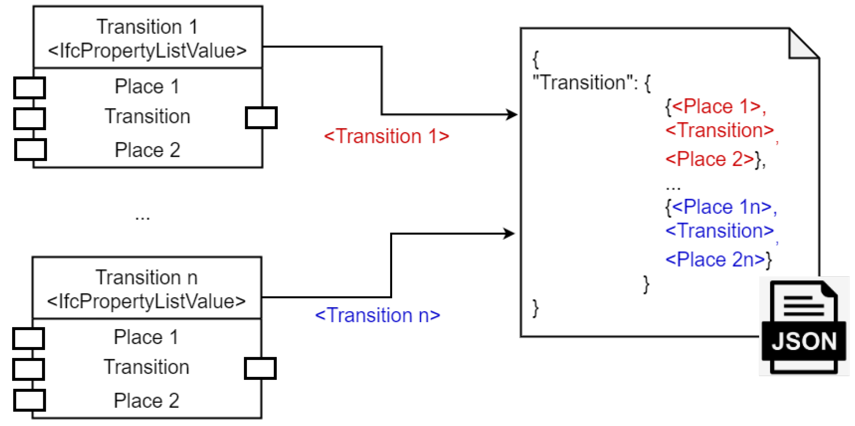
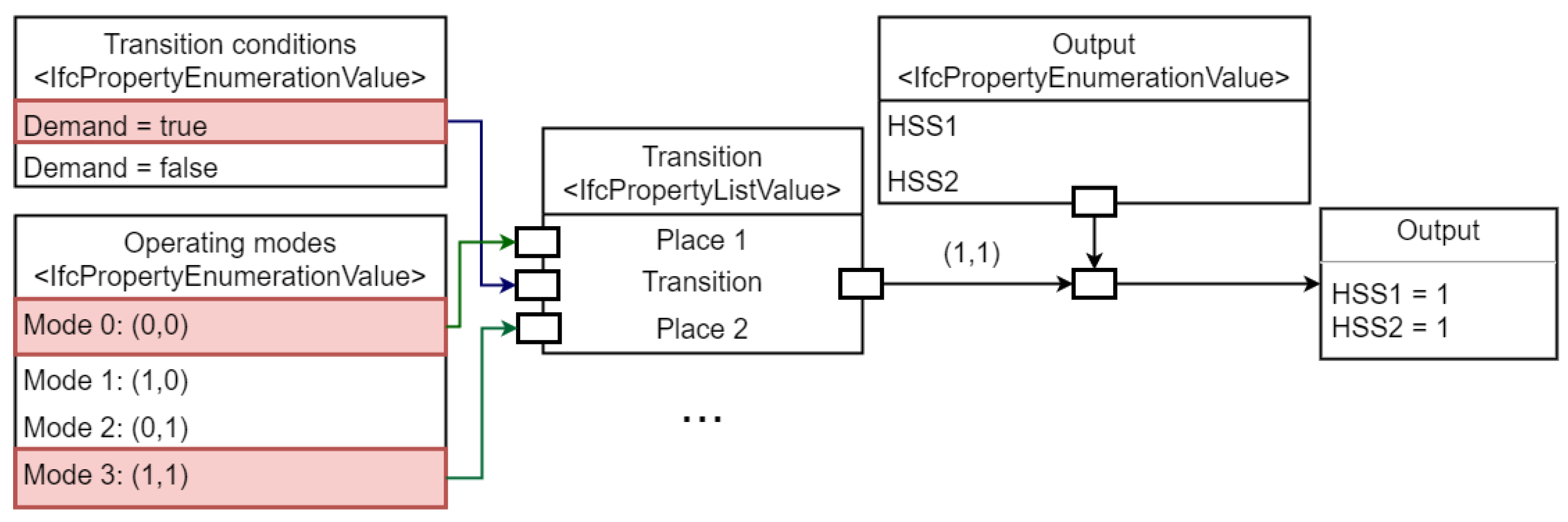
2.1.2. SIPN-Described Control Logic in the IFC Schema
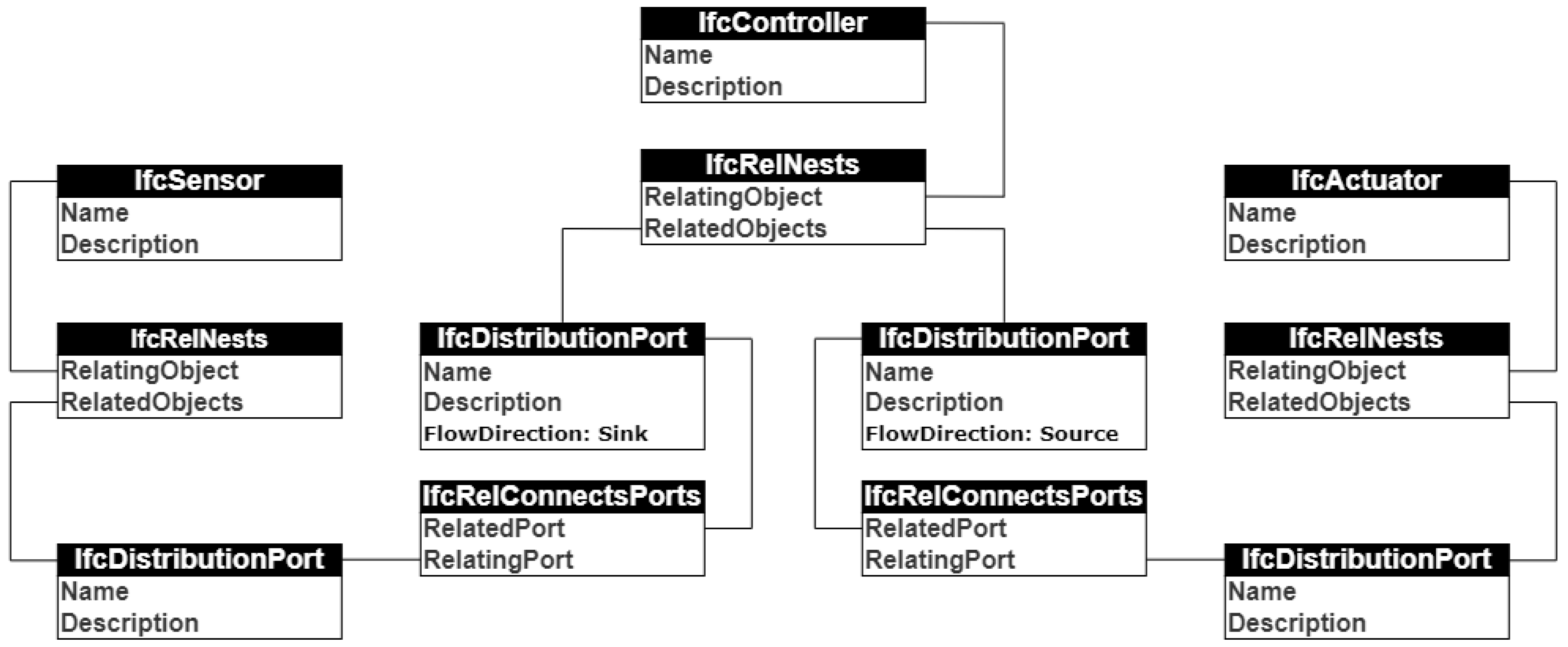
2.1.3. Bridging Controllers and Physical Systems in the IFC Schema
2.2. Automated Implementation of IFC-Based Mode-Based Control Algorithms in PLC
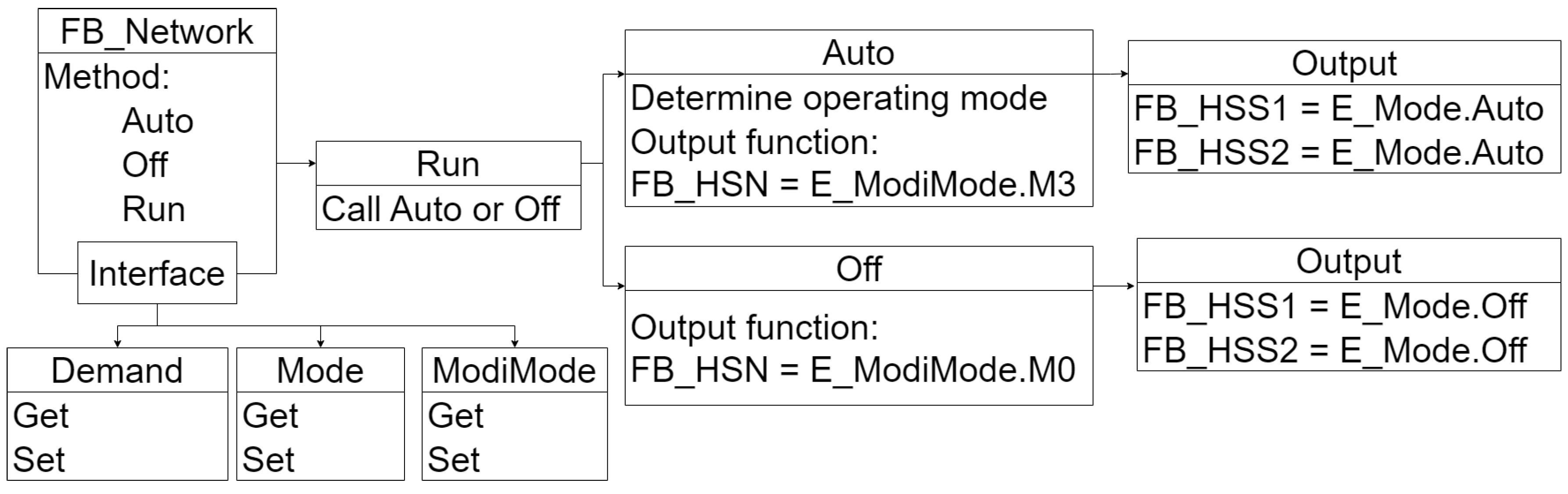
2.2.1. Implementation of IFC-based mode-based control algorithms in ST
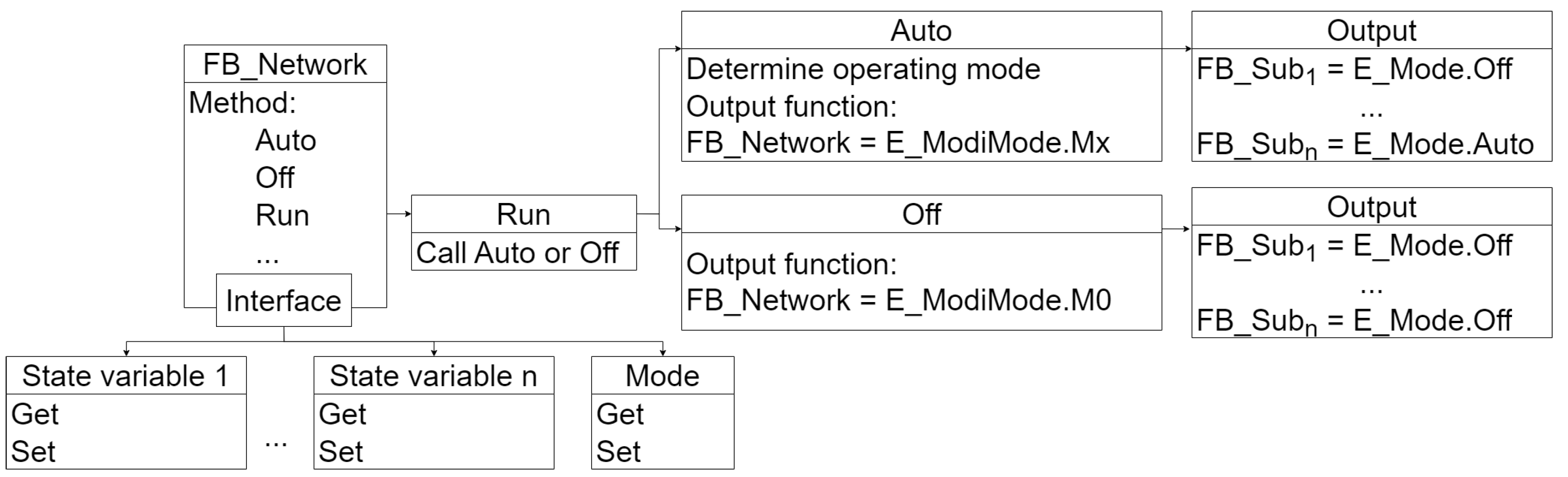
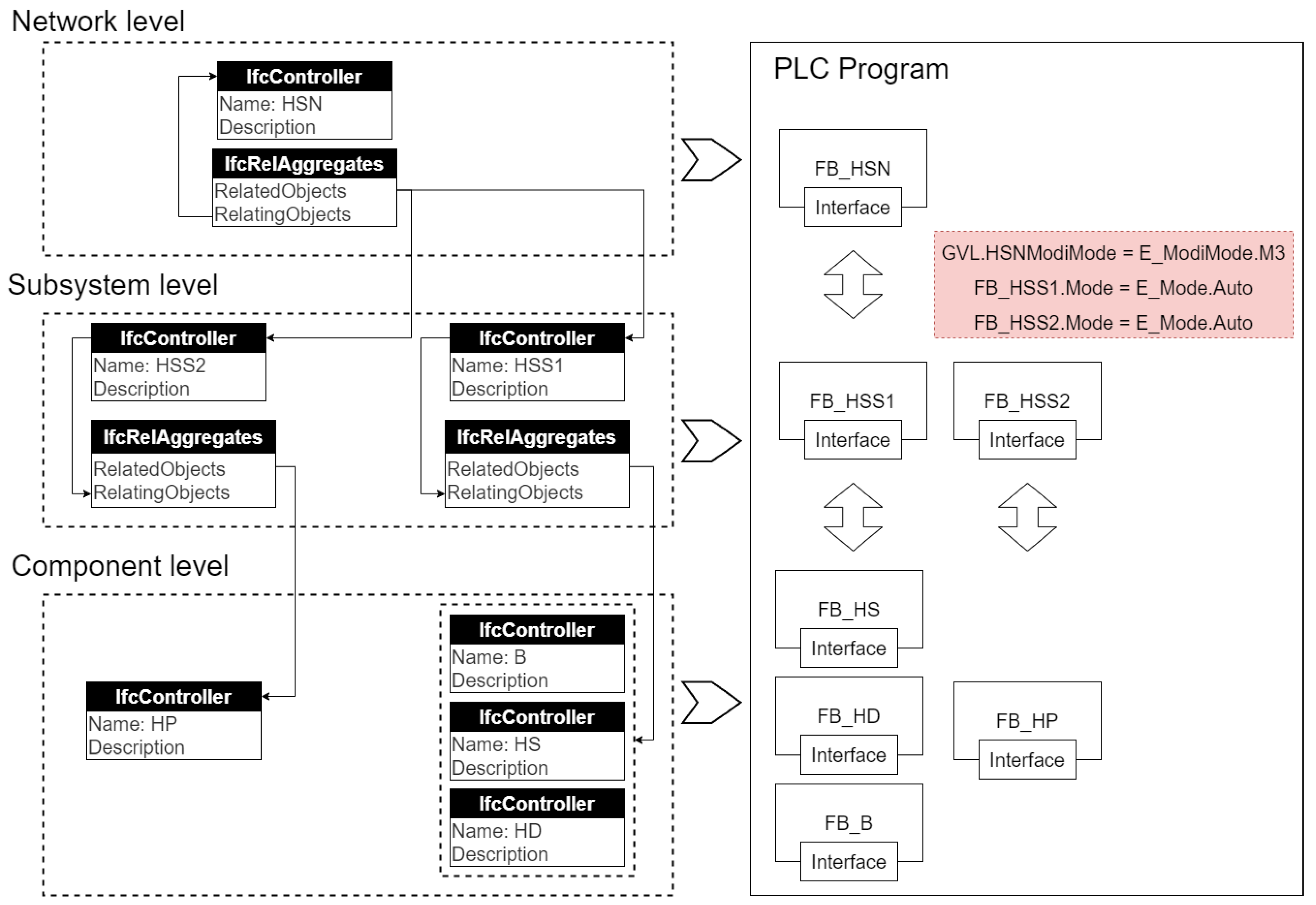
- Mapping hierarchically structured mode-based control algorithms expressed by the IFC schema to corresponding hierarchical PLC programs
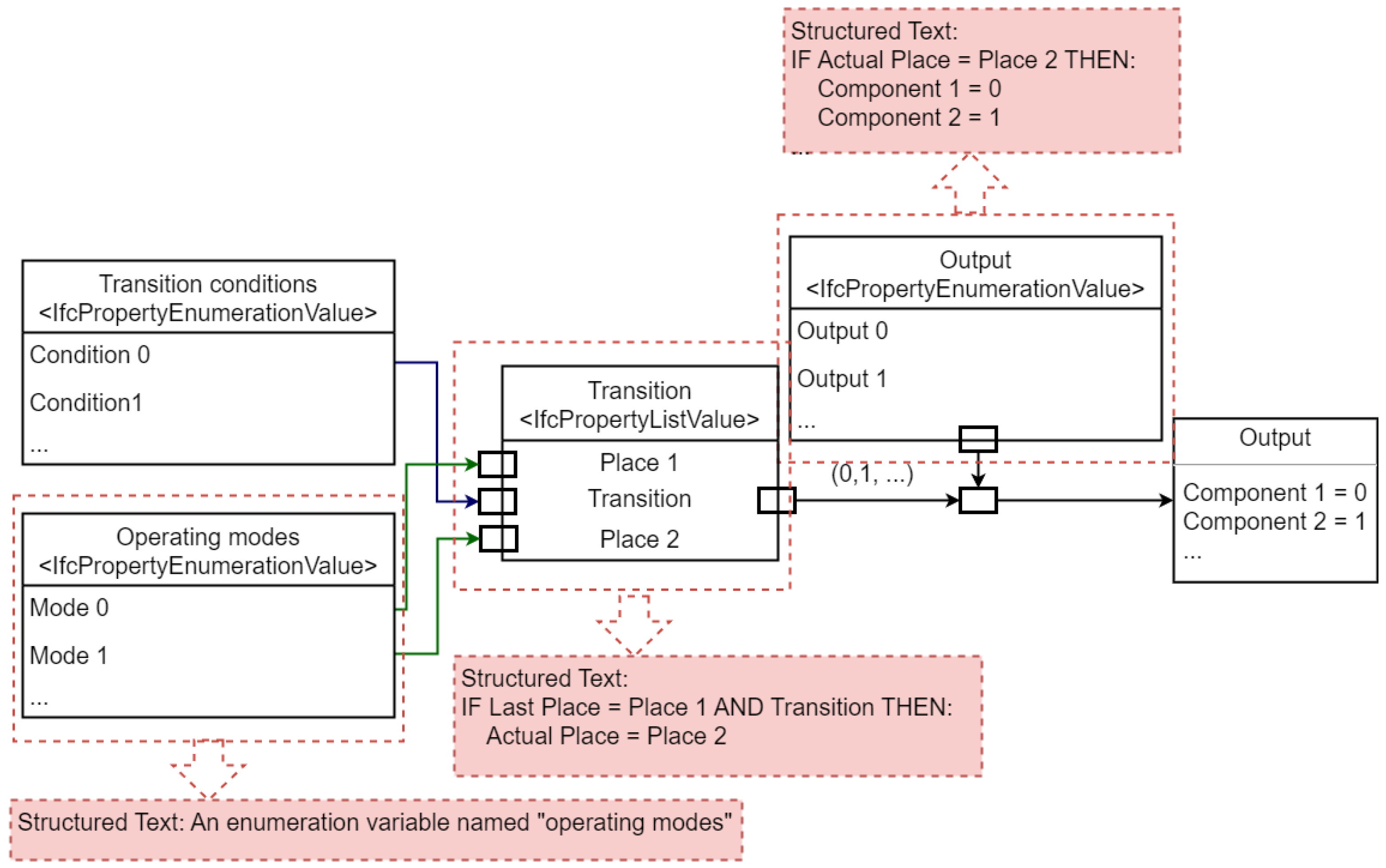
- One-to-one correspondence of the IFC properties to the ST code segments
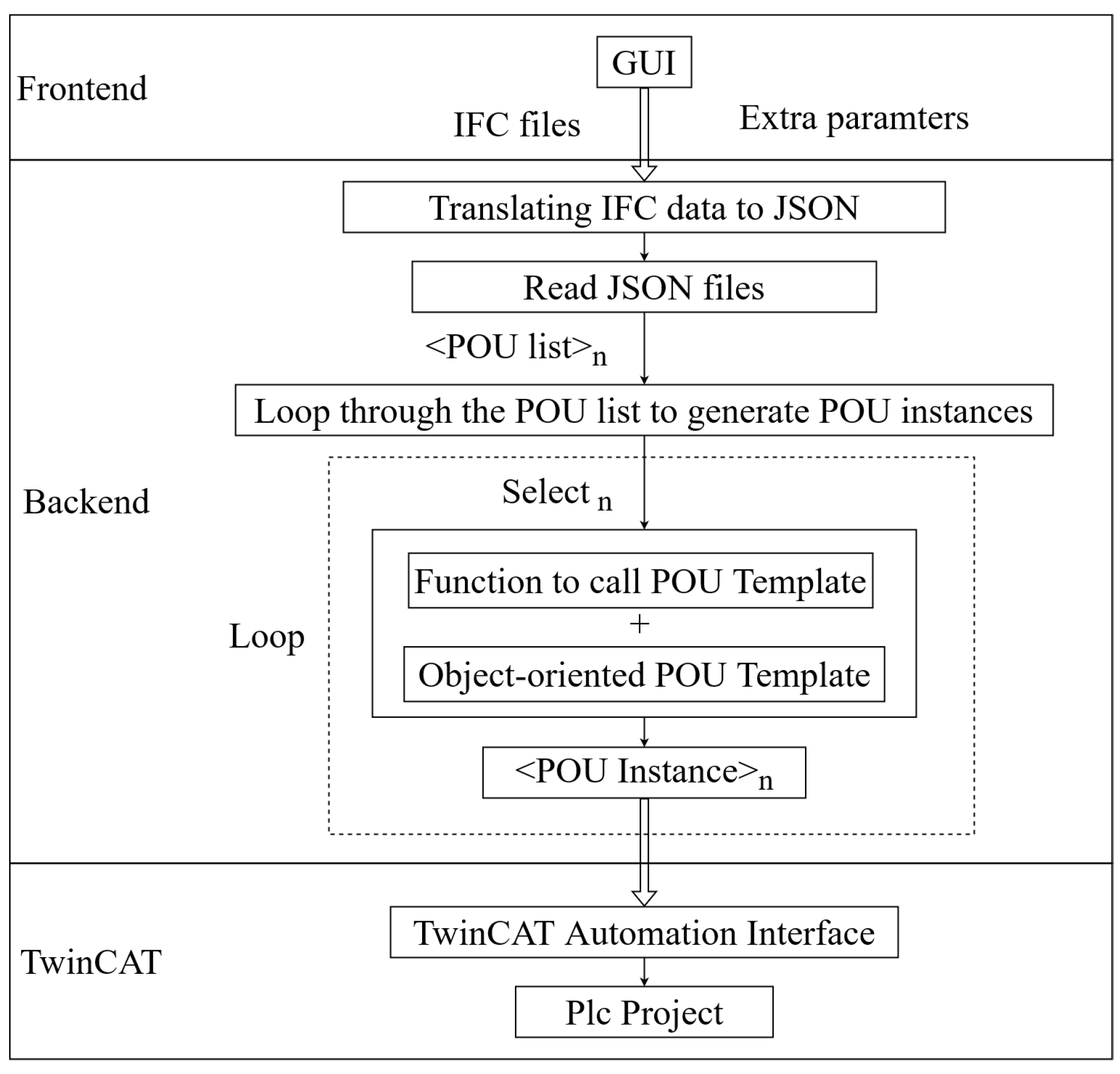
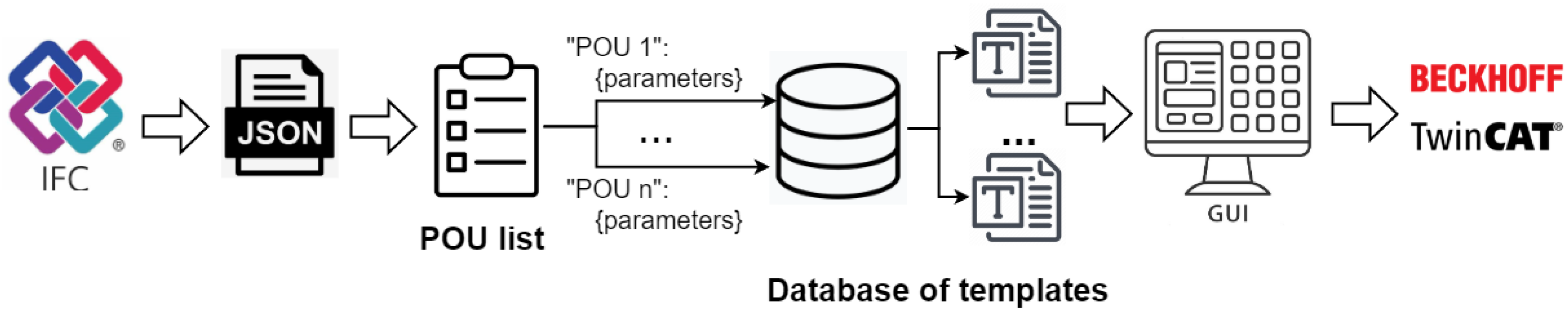
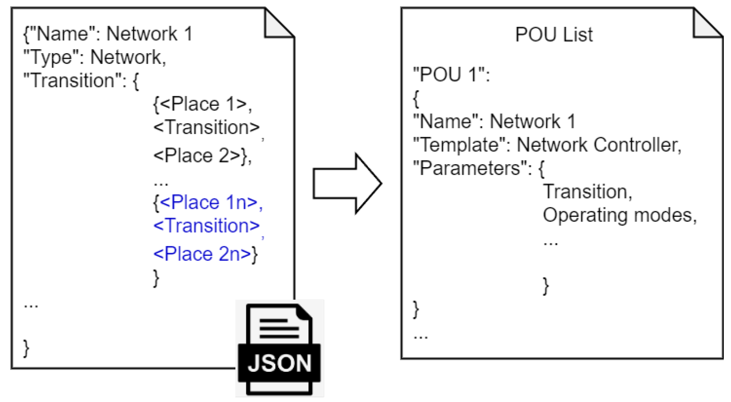
2.2.2. Software-Assisted Generation of ST to Implement IFC-Based Mode-Based Control Algorithms in PLC
3. Use Case
3.1. Documentation of a Mode-Based Control Strategy for the Desired Energy System
3.2. Implementation of a Mode-Based Control Strategy by Generating PLC Code for the Desired Energy System
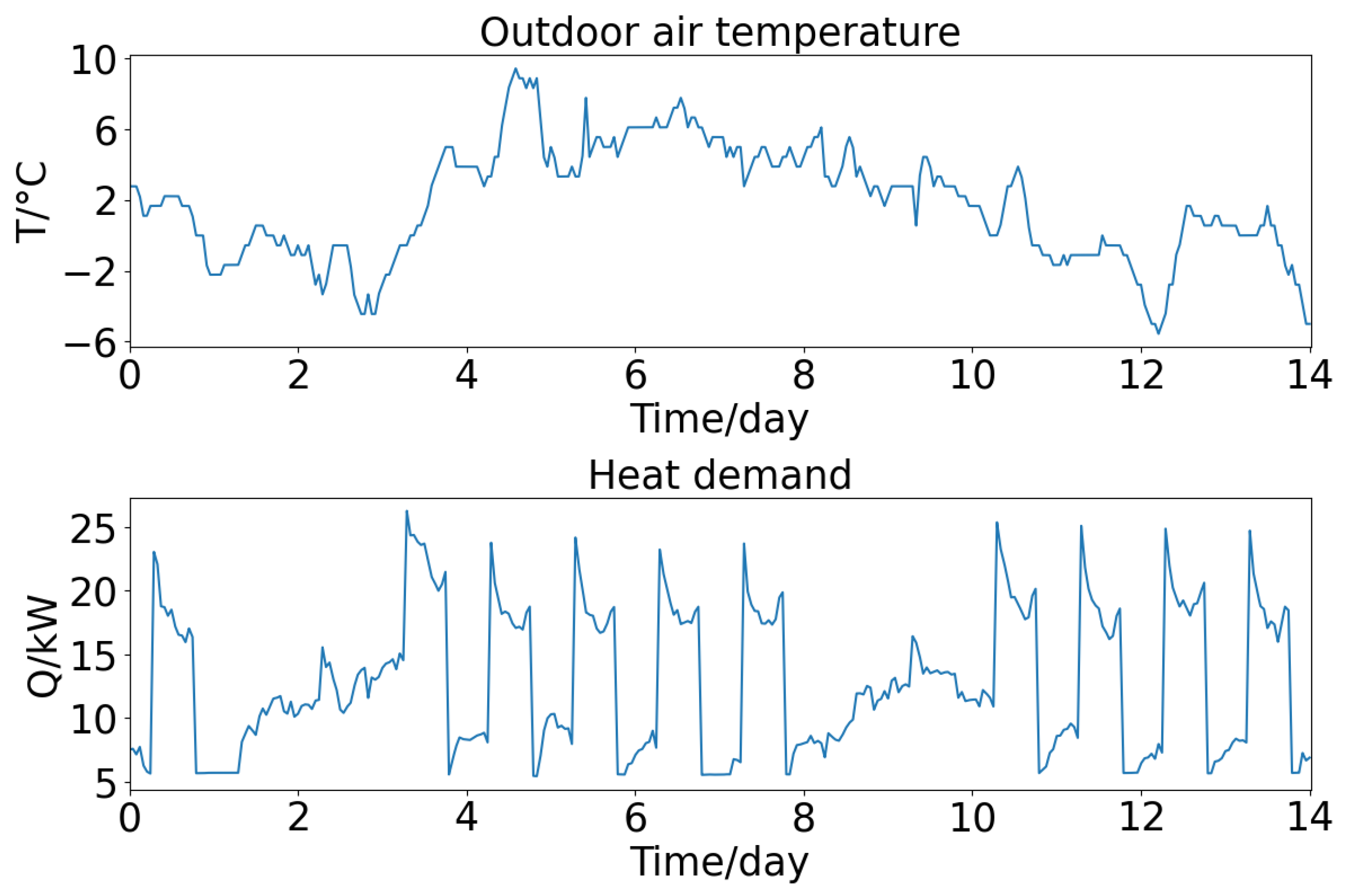
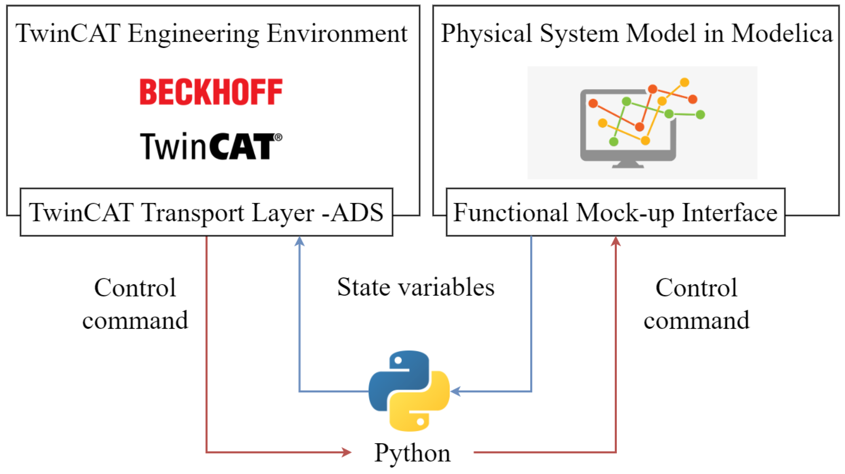
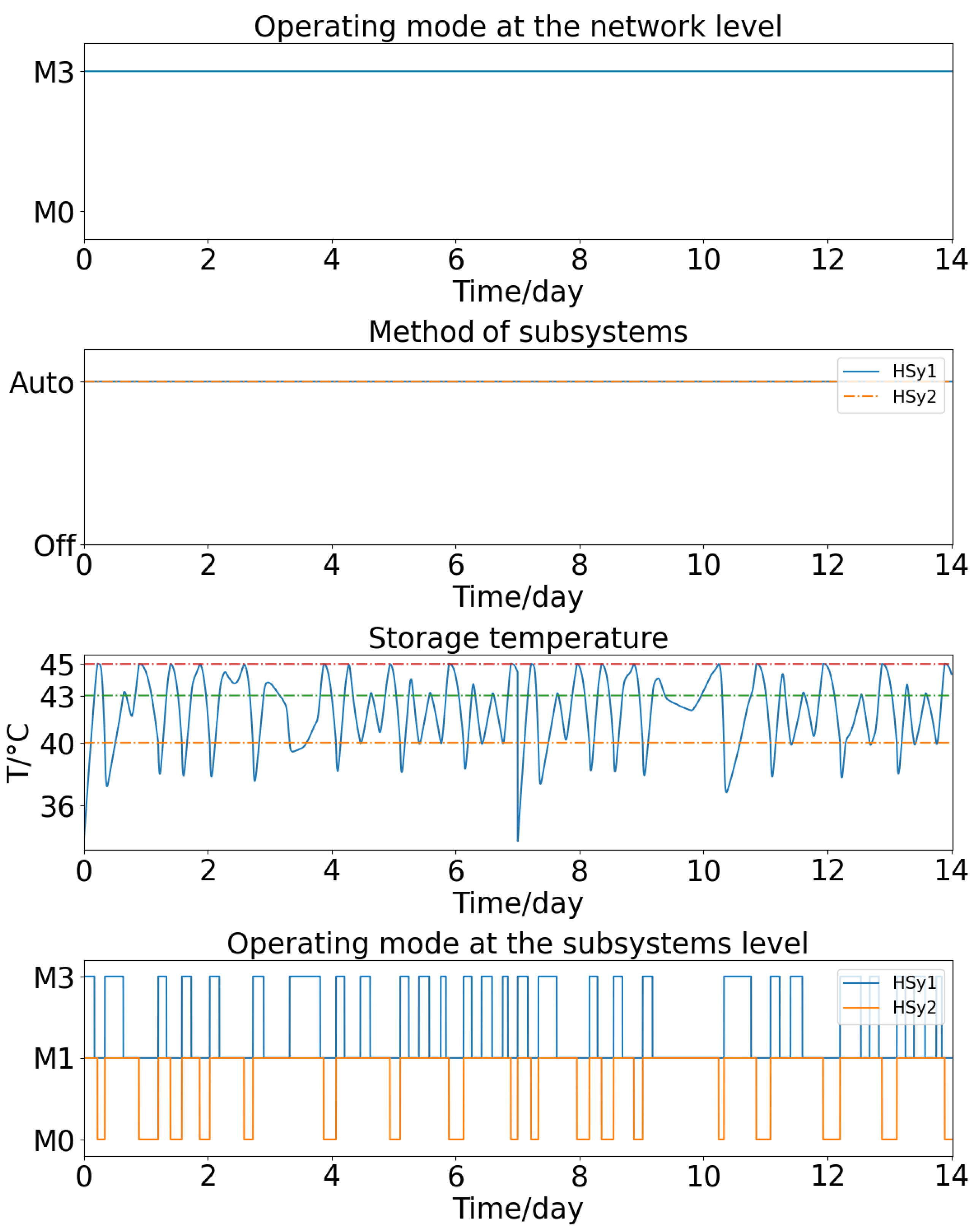
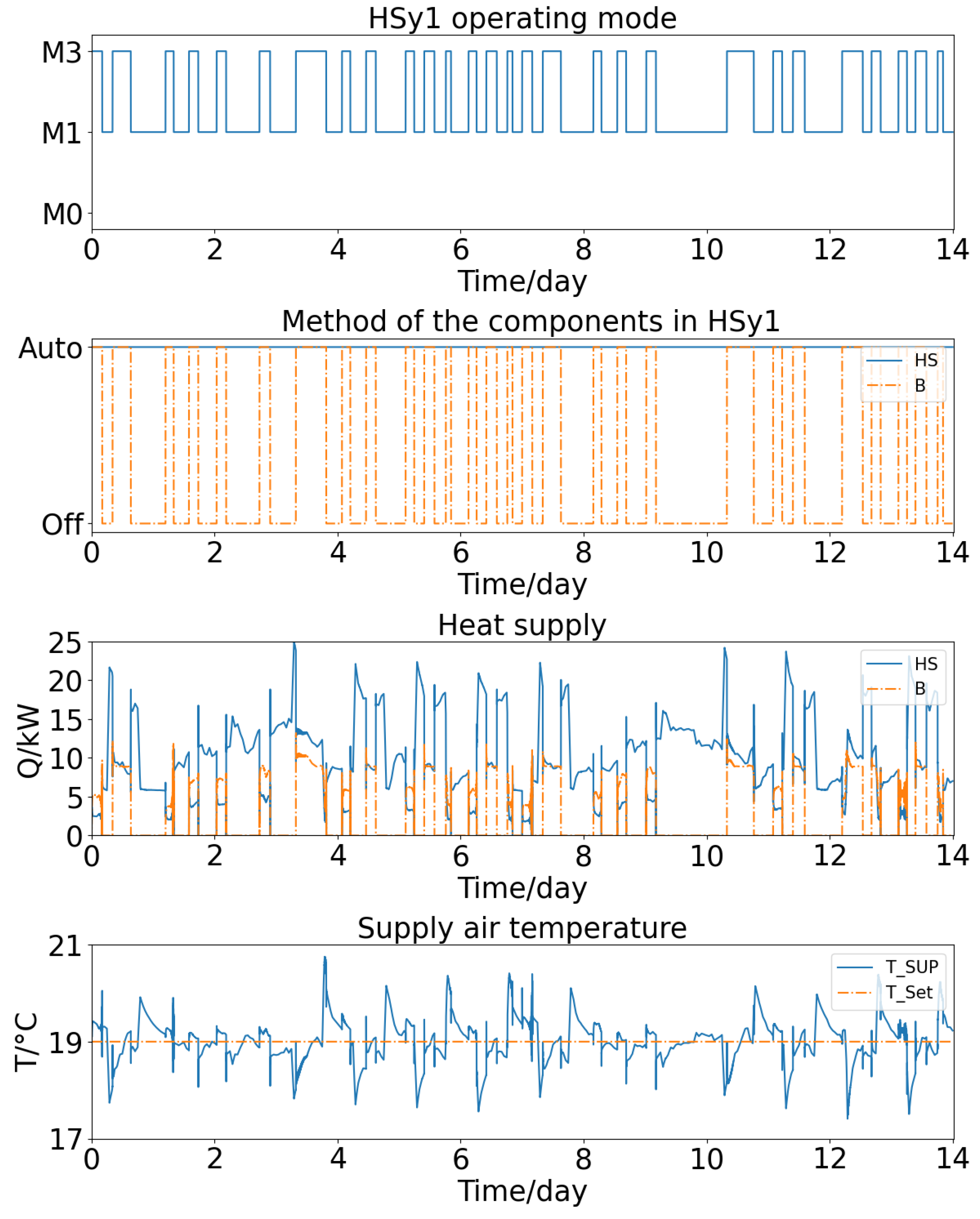
3.3. Simulation-Assisted Evaluation of the Implemented Control Strategy
3.4. Discussion
4. Conclusions
Author Contributions
Funding
Data Availability Statement
Acknowledgments
Conflicts of Interest
References
- Buildings: A Source of Enormous Untapped Efficiency Potential. Available online: https://www.iea.org/topics/buildings (accessed on 24 October 2023).
- de Wilde, P. The gap between predicted and measured energy performance of buildings: A framework for investigation. Autom. Constr. 2014, 41, 40–49. [Google Scholar] [CrossRef]
- Jain, N. Reducing the Performance Gap Using Calibrated Simulation Models. Doctoral Dissertation, UCL (University College London), London, UK, 2021. [Google Scholar]
- Lei, X.; Chen, Y.; Bergés, M.; Akinci, B. Formalized control logic fault definition with ontological reasoning for air handling units. Autom. Constr. 2021, 129, 103781. [Google Scholar] [CrossRef]
- Schneider, G.F.; Kontes, G.D.; Qiu, H.; Silva, F.J.; Bucur, M.; Malanik, J.; Schindler, Z.; Andriopolous, P.; de Agustin-Camacho, P.; Romero-Amorrortu, A.; et al. Design of knowledge-based systems for automated deployment of building management services. Autom. Constr. 2020, 119, 103402. [Google Scholar] [CrossRef]
- Mishra, S.; Glaws, A.; Cutler, D.; Frank, S.; Azam, M.; Mohammadi, F.; Venne, J.S. Unified architecture for data-driven metadata tagging of building automation systems. Autom. Constr. 2020, 120, 103411. [Google Scholar] [CrossRef]
- Ruiz-Zafra, A.; Benghazi, K.; Noguera, M. IFC+: Towards the integration of IoT into early stages of building design. Autom. Constr. 2022, 136, 104129. [Google Scholar] [CrossRef]
- Abdel Haleem, S.M.; Pavlak, G.S.; Bahnfleth, W.P. Impact of control loop performance on energy use, air quality, and thermal comfort in building systems with advanced sequences of operation. Autom. Constr. 2021, 130, 103837. [Google Scholar] [CrossRef]
- EN 15232-1:2017; Energy Performance of Buildings—Energy performance of buildings—Part 1: Impact of Building Automation, Controls and Building Management—Modules M10-4,5,6,7,8,9,10. Autom. Constr. 2022. Available online: https://standards.iteh.ai/catalog/standards/cen/d9e4b452-93a7-4b7e-b8f8-90e37adddbc2/en-15232-1-2017 (accessed on 24 October 2023).
- Schneider, G.F.; Pauwels, P.; Steiger, S. Ontology-Based Modeling of Control Logic in Building Automation Systems. IEEE Trans. Ind. Inform. 2017, 13, 3350–3360. [Google Scholar] [CrossRef]
- Pauwels, P.; Terkaj, W. EXPRESS to OWL for construction industry: Towards a recommendable and usable ifcOWL ontology. Autom. Constr. 2015, 63, 100–133. [Google Scholar] [CrossRef]
- Strahilov, A.; Hämmerle, H. Engineering Workflow and Software Tool Chains of Automated Production Systems. In Multi-Disciplinary Engineering for Cyber-Physical Production Systems: Data Models and Software Solutions for Handling Complex Engineering Projects; Biffl, S., Lüder, A., Gerhard, D., Eds.; Springer International Publishing: Berlin/Heidelberg, Germany, 2017; pp. 207–234. [Google Scholar] [CrossRef]
- Corry, E.; Pauwels, P.; Hu, S.; Keane, M.; O’Donnell, J. A performance assessment ontology for the environmental and energy management of buildings. Autom. Constr. 2015, 57, 249–259. [Google Scholar] [CrossRef]
- Wetter, M.; Ehrlich, P.; Gautier, A.; Grahovac, M.; Haves, P.; Hu, J.; Prakash, A.; Robin, D.; Zhang, K. OpenBuildingControl: Digitizing the control delivery from building energy modeling to specification, implementation and formal verification. Energy 2021, 238, 121501. [Google Scholar] [CrossRef]
- Wang, W.; Brambley, M.R.; Kim, W.; Somasundaram, S.; Stevens, A.J. Automated point mapping for building control systems: Recent advances and future research needs. Autom. Constr. 2017, 85, 107–123. [Google Scholar] [CrossRef]
- Wong, J.K.W.; Ge, J.; He, S.X. Digitisation in facilities management: A literature review and future research directions. Autom. Constr. 2018, 92, 312–326. [Google Scholar] [CrossRef]
- Cai, X.; Xue, J.; Kümpel, A.; Müller, D. Automated Modelling of Building Energy Systems with Mode-Based Control Algorithms in Modelica. J. Phys. Conf. Ser. 2021, 2042, 012067. [Google Scholar] [CrossRef]
- Cai, X.; Schild, T.; Kümpel, A.; Müller, D. MODI: A Structured Development Process of Mode-Based Control Algorithms in the Early Design Stage of Building Energy Systems. Buildings 2023, 13, 267. [Google Scholar] [CrossRef]
- Cai, X.; Schild, T.; Schreiber, T.; Baranski, M.; Müller, D. Modeling of Petri-Net-based control algorithms for the simulation-based improvement of the planning process of building energy systems. J. Phys. Conf. Ser. 2019, 1343, 012123. [Google Scholar] [CrossRef]
- Cai, X.; Shi, R.; Kümpell, A.; Müller, D. Automated generation of PLC code for implementing mode-based control algorithms in buildings. In Proceedings of the 2022 30th Mediterranean Conference on Control and Automation (MED), Vouliagmeni, Greece, 28 June–1 July 2022; pp. 1087–1092. [Google Scholar] [CrossRef]
- Afsari, K.; Eastman, C.M.; Castro-Lacouture, D. JavaScript Object Notation (JSON) data serialization for IFC schema in web-based BIM data exchange. Autom. Constr. 2017, 77, 24–51. [Google Scholar] [CrossRef]
- Pereira, V.; Santos, J.; Leite, F.; Escórcio, P. Using BIM to improve building energy efficiency – A scientometric and systematic review. Energy Build. 2021, 250, 111292. [Google Scholar] [CrossRef]
- Tang, S.; Shelden, D.R.; Eastman, C.M.; Pishdad-Bozorgi, P.; Gao, X. BIM assisted Building Automation System information exchange using BACnet and IFC. Autom. Constr. 2019, 110, 103049. [Google Scholar] [CrossRef]
- Ying, H.; Lee, S. An algorithm to facet curved walls in IFC BIM for building energy analysis. Autom. Constr. 2019, 103, 80–103. [Google Scholar] [CrossRef]
- Alavi, H.; Bortolini, R.; Forcada, N. BIM-based decision support for building condition assessment. Autom. Constr. 2021, 135, 104117. [Google Scholar] [CrossRef]
- Dong, B.; O’Neill, Z.; Li, Z. A BIM-enabled information infrastructure for building energy Fault Detection and Diagnostics. Autom. Constr. 2014, 44, 197–211. [Google Scholar] [CrossRef]
- Revit Software|Get Prices & Buy Official Revit 2023. Available online: https://www.autodesk.com/products/revit/overview (accessed on 24 October 2023).
- Archicad Software. Available online: https://graphisoft.com/solutions/archicad (accessed on 24 October 2023).
- ISO 16739-1:2018; Industry Foundation Classes (IFC) for data sharing in the construction and facility management industries, Part 1: Data schema. International Organization for Standardization: Geneva, Switzerland, 2018. Available online: https://www.iso.org/standard/70303.html (accessed on 24 October 2023).
- Seidenschnur, M.; Kücükavci, A.; Fjerbæk, E.V.; Smith, K.M.; Pauwels, P.; Hviid, C.A. A common data environment for HVAC design and engineering. Autom. Constr. 2022, 142, 104500. [Google Scholar] [CrossRef]
- Quinn, C.; Shabestari, A.Z.; Misic, T.; Gilani, S.; Litoiu, M.; McArthur, J.J. Building automation system—BIM integration using a linked data structure. Autom. Constr. 2020, 118, 103257. [Google Scholar] [CrossRef]
- Gao, X.; Pishdad-Bozorgi, P. BIM-enabled facilities operation and maintenance: A review. Adv. Eng. Inform. 2019, 39, 227–247. [Google Scholar] [CrossRef]
- Sporr, A.; Zucker, G.; Hofmann, R. Automatically Creating HVAC Control Strategies Based on Building Information Modeling (BIM): Heat Provisioning and Distribution. Energies 2020, 13, 4403. [Google Scholar] [CrossRef]
- Gao, H.; Koch, C.; Wu, Y. Building information modelling based building energy modelling: A review. Appl. Energy 2019, 238, 320–343. [Google Scholar] [CrossRef]
- Cerovsek, T. A review and outlook for a ‘Building Information Model’ (BIM): A multi-standpoint framework for technological development. Adv. Eng. Inform. 2011, 25, 224–244. [Google Scholar] [CrossRef]
- Jia, M.; Komeily, A.; Wang, Y.; Srinivasan, R.S. Adopting Internet of Things for the development of smart buildings: A review of enabling technologies and applications. Autom. Constr. 2019, 101, 111–126. [Google Scholar] [CrossRef]
- Merz, H.; Hansemann, T.; Hübner, C. Building Automation; Signals and Communication Technology; Springer International Publishing: Berlin/Heidelberg, Germany, 2018. [Google Scholar] [CrossRef]
- Martirano, L.; Mitolo, M. Building Automation and Control Systems (BACS): A Review. In Proceedings of the 2020 IEEE International Conference on Environment and Electrical Engineering and 2020 IEEE Industrial and Commercial Power Systems Europe (EEEIC/I CPS Europe), Madrid, Spain, 9–12 June 2020; pp. 1–8. [Google Scholar] [CrossRef]
- Domingues, P.; Carreira, P.; Vieira, R.; Kastner, W. Building automation systems: Concepts and technology review. Comput. Stand. Interfaces 2015, 45, 1–12. [Google Scholar] [CrossRef]
- Quezada, J.C.; Medina, J.; Flores, E.; Seck Tuoh, J.C.; Hernández, N. Formal design methodology for transforming ladder diagram to Petri nets. Int. J. Adv. Manuf. Technol. 2014, 73, 821–836. [Google Scholar] [CrossRef]
- IEC 61131-3:2013; Programmable Controllers-Part 3: Programming Languages. International Electrotechnical Commission: Geneva, Switzerland, 2010.
- Werner, B. Object-oriented extensions for IEC 61131-3. IEEE Ind. Electron. Mag. 2014, 3, 36–39. [Google Scholar] [CrossRef]
- Chen, Y.; Dai, W.; Zhang, Z.; Pang, C.; Vyatkin, V. A Case Study on Knowledge Driven Code Generation for Software-Defined Industrial Cyber-Physical Systems. In Proceedings of the IECON 2018—44th Annual Conference of the IEEE Industrial Electronics Society, Washington, DC, USA, 21–23 October 2018; pp. 4687–4692. [Google Scholar] [CrossRef]
- Estévez, E.; Marcos, M.; Orive, D. Automatic generation of PLC automation projects from component-based models. Int. J. Adv. Manuf. Technol. 2007, 35, 527–540. [Google Scholar] [CrossRef]
- Vogel-Heuser, B.; Fischer, J.; Feldmann, S.; Ulewicz, S.; Rösch, S. Modularity and architecture of PLC-based software for automated production Systems: An analysis in industrial companies. J. Syst. Softw. 2017, 131, 35–62. [Google Scholar] [CrossRef]
- Zhang, J.; Ahmad, B.; Harrison, R.; Colombo, A.W.; Raasch, S. An approach for resource Function Block generation: Towards RAMI4.0-compliant PLC Programming. In Proceedings of the 2020 IEEE 18th International Conference on Industrial Informatics (INDIN), Warwick, UK, 20–23 July 2020; Volume 1, pp. 595–600. [Google Scholar] [CrossRef]
- Jbair, M.; Ahmad, B.; Ahmad, M.H.; Vera, D.; Harrison, R.; Ridler, T. Automatic PLC Code Generation Based on Virtual Engineering Model. In Proceedings of the 2019 IEEE International Conference on Industrial Cyber Physical Systems (ICPS), Taipei, Taiwan, 6–9 May 2019; pp. 675–680. [Google Scholar] [CrossRef]
- Armentia, A.; Estévez, E.; Orive, D.; Marcos, M. A Tool Suite for Automatic Generation of Modular Machine Automation Projects. In Proceedings of the 2018 IEEE 16th International Conference on Industrial Informatics (INDIN), Porto, Portugal, 18–20 July 2018; pp. 553–558. [Google Scholar] [CrossRef]
- Fischer, J.; Vogel-Heuser, B.; Friedrich, D. Configuration of PLC software for automated warehouses based on reusable components- an industrial case study. In Proceedings of the 2015 IEEE 20th Conference on Emerging Technologies & Factory Automation (ETFA), Luxembourg, 8–11 September 2015; pp. 1–7. [Google Scholar] [CrossRef]
- Pavlovskyi, Y.; Kennel, M.; Schmucker, U. Template-Based Generation of PLC Software from Plant Models Using Graph Representation. In Proceedings of the 2018 25th International Conference on Mechatronics and Machine Vision in Practice (M2VIP), Stuttgart, Germany, 20–22 November 2018; pp. 1–8. [Google Scholar] [CrossRef]
- Darvas, D.; Viñuela, E.B.; Majzik, I. PLC code generation based on a formal specification language. In Proceedings of the 2016 IEEE 14th International Conference on Industrial Informatics (INDIN), Poitiers, France, 19–21 July 2016; pp. 389–396. [Google Scholar] [CrossRef]
- Weiß, M.; Marks, P.; Maschler, B.; White, D.; Kesseli, P.; Weyrich, M. Towards establishing formal verification and inductive code synthesis in the PLC domain. In Proceedings of the 2021 IEEE 19th International Conference on Industrial Informatics (INDIN), Palma de Mallorca, Spain, 21–23 July 2021; pp. 1–8. [Google Scholar] [CrossRef]
- Barbosa, H.; Déharbe, D. Formal Verification of PLC Programs Using the B Method. In Abstract State Machines, Alloy, B, VDM, and Z; Lecture Notes in Computer Science; Derrick, J., Fitzgerald, J., Gnesi, S., Khurshid, S., Leuschel, M., Reeves, S., Riccobene, E., Eds.; Springer: Berlin/Heidelberg, Germany, 2012; pp. 353–356. [Google Scholar] [CrossRef]
- Darvas, D.; Majzik, I.; Blanco Viñuela, E. Formal Verification of Safety PLC Based Control Software. In Integrated Formal Methods; Lecture Notes in Computer Science; Ábrahám, E., Huisman, M., Eds.; Springer International Publishing: Berlin/Heidelberg, Germany, 2016; pp. 508–522. [Google Scholar] [CrossRef]
- Jbair, M.; Ahmad, B.; Ahmad, M.H.; Harrison, R. Industrial cyber physical systems: A survey for control-engineering tools. In Proceedings of the 2018 IEEE Industrial Cyber-Physical Systems (ICPS), St. Petersburg, Russia, 15–18 May 2018; pp. 270–276. [Google Scholar] [CrossRef]
- Germany, Hülshorstweg 20, V.B.A.G.\.C.K. TwinCAT|Automation software. Available online: https://www.beckhoff.com/en-en/products/automation/twincat/ (accessed on 24 October 2023).
- UAG Unity Application Generator|Schneider Electric Egypt. Available online: https://www.se.com/eg/en/product-range/628-uag-unity-application-generator/ (accessed on 24 October 2023).
- Mitsubishi Adroit Process Suite (MAPS)|Maps SCADA. Available online: https://www.mapsscada.com/mitsubishi-adroit-process-suite-maps/ (accessed on 24 October 2023).
- Modelica Language—Modelica Association. Available online: https://modelica.org/modelicalanguage.html (accessed on 24 October 2023).
- Chen, Y.; Treado, S.J.; Messner, J.I. Building HVAC control knowledge data schema—Towards a unified representation of control system knowledge. Autom. Constr. 2016, 72, 174–186. [Google Scholar] [CrossRef]
- Chen, Y. Building Control Knowledge Information Modeling and Control Self-Configuration. Ph.D. Thesis, Pennsylvania State University, State College, PA, USA, 2015. [Google Scholar]
- Benndorf, G.; Réhault, N.; Clairembault, M.; Rist, T. Describing HVAC controls in IFC – Method and application. Energy Procedia 2017, 122, 319–324. [Google Scholar] [CrossRef]
- Krima, S.; Barbau, R.; Fiorentini, X.; Rachuri, S.; Sriram, R. OntoSTEP: OWL-DL ontology for STEP. In Proceedings of the International Conference on Product Lifecycle Management PLM’09 Publication, Bath, UK, 6–8 July 2009. [Google Scholar]
- Barbau, R.; Krima, S.; Rachuri, S.; Narayanan, A.; Fiorentini, X.; Foufou, S.; Sriram, R.D. OntoSTEP: Enriching product model data using ontologies. Comput.-Aided Des. 2012, 44, 575–590. [Google Scholar] [CrossRef]
- Pauwels, P.; Zhang, S.; Lee, Y.C. Semantic web technologies in AEC industry: A literature overview. Autom. Constr. 2017, 73, 145–165. [Google Scholar] [CrossRef]
- Terkaj, W.; Šojić, A. Ontology-based representation of IFC EXPRESS rules: An enhancement of the ifcOWL ontology. Autom. Constr. 2015, 57, 188–201. [Google Scholar] [CrossRef]
- Kukkonen, V.; Kücükavci, A.; Seidenschnur, M.; Rasmussen, M.H.; Smith, K.M.; Hviid, C.A. An ontology to support flow system descriptions from design to operation of buildings. Autom. Constr. 2021, 134, 104067. [Google Scholar] [CrossRef]
- IfcOpenShell. Available online: http://ifcopenshell.org/ (accessed on 24 October 2023).
- buildingSMART Technical. Industry Foundation Classes (IFC). Available online: https://technical.buildingsmart.org/standards/ifc/ (accessed on 24 October 2023).
- AixOCAT—Library framework for building automation systems based on the OSCAT libraries. RWTH Aachen University—E.ON Energy Research Center—Institute for Energy Efficient Buildings and Indoor Climate. original-date: 2018-04-11T08:39:49Z. Available online: https://github.com/RWTH-EBC/AixOCAT (accessed on 24 October 2023).
- BACnet PICS CIM 300. Available online: https://www.bacnetinternational.net/catalog/manu/grundfos%20management%20as/97750025_1114_BACnet%20PICS%20CIM%20300_IO_GB.PDF (accessed on 24 October 2023).
- Functional Mock-up Interface. Available online: https://fmi-standard.org/ (accessed on 24 October 2023).
- Welcome to pyads’s Documentation!—pyads 3.3.9 Documentation. Available online: https://pyads.readthedocs.io/en/latest/index.html (accessed on 24 October 2023).
- Müller, D.; Lauster, M.; Constantin, A.; Fuchs, M.; Remmen, P. AixLib—An Open-Source Modelica Library within the IEA-EBC Annex 60 Framework. BauSIM 2016, 2016, 3–9. [Google Scholar]
- Wetter, M.; Zuo, W.; Nouidui, T.S.; Pang, X. Modelica Buildings library. J. Build. Perform. Simul. 2013, 7, 253–270. [Google Scholar] [CrossRef]
- EnArgus. Available online: https://www.enargus.de/pub/bscw.cgi/?op=enargus.eps2&q=Leuphana&v=10&id=372001 (accessed on 24 October 2023).


| IFC Entities | Description |
|---|---|
| IfcController | A controller within a BACS. |
| IfcRealAggregates | The aggregation relationship applied to IfcObject. |
| IfcSimpleProperty | A generalization of a single property object, including IfcPropertySingleValue, IfcPropertyEnumeratedValue, IfcPropertyBoundedValue, IfcPropertyTableValue, IfcPropertyReferenceValue, IfcPropertyListValue. |
| IfcComplexProperty | Complex properties, which can be a collection of IfcProperty subtypes. |
| IfcRelDefinedByProperty | The relationship between objects and a property set. |
| IfcPropertySet | A container class holding properties within a property set. |
| IfcActor | An actor within a BACS. |
| IfcSensor | A sensor within a BACS. |
| IfcDistributionPort | A specialized interface for distribution elements. |
| IfcRelNests | The nesting relationship for the general composition or decomposition relationship. |
| IfcRelConnectPorts | The connection relationship between two ports. |
| SIPN | IfcPropertyEnumerationValue | Description |
|---|---|---|
| Places | Operating modes | Listing all permissible operating modes |
| Transition conditions | State variables | Listing all relevant state variables |
| Transition conditions | Listing all possible mode-switching conditions | |
| Output functions | Output | Listing system behaviors by activating operating modes |
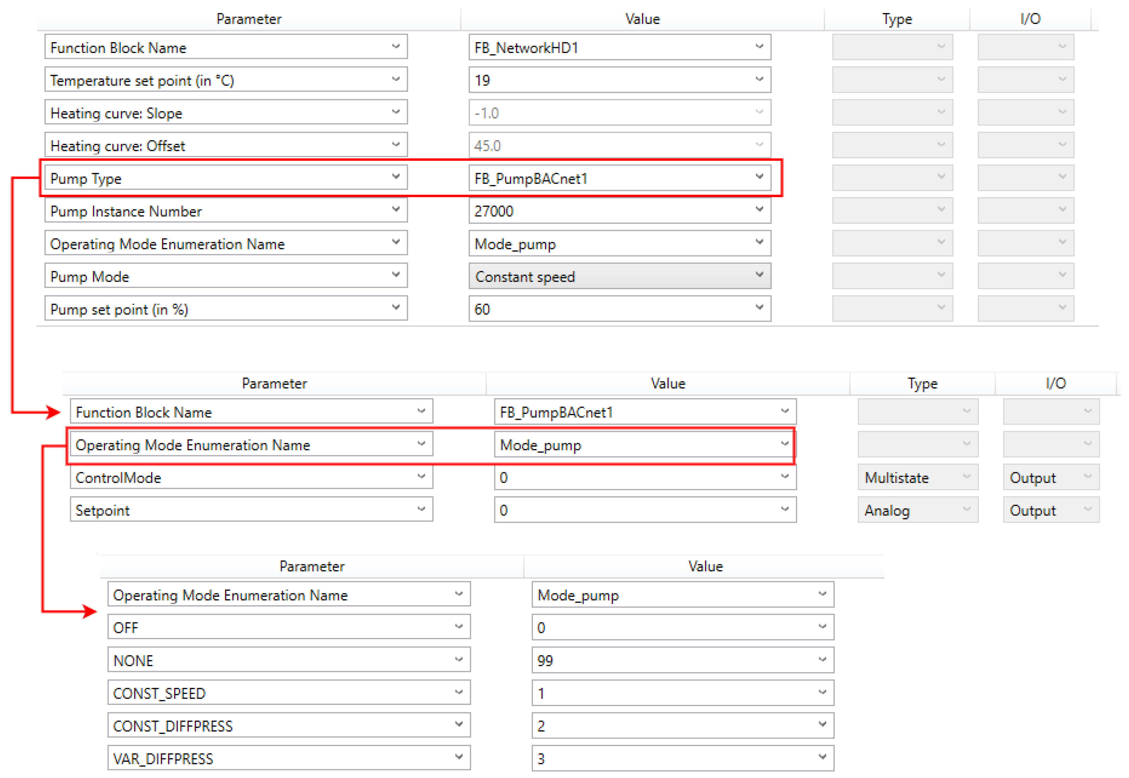
| Object Type | ID | Name | Description |
|---|---|---|---|
| Multistate output (MO) | 0 | Set controlmode | 1: Constant speed |
| 2: Constant pressure | |||
| 3: Proportional pressure | |||
| … | |||
| Analog output (AO) | 0 | Set setpoint | Sets the pump setpoint. |
| Function Blocks | Methods | Global Variables | Local Variables |
|---|---|---|---|
| 7 | 21 | 23 | 71 |
Disclaimer/Publisher’s Note: The statements, opinions and data contained in all publications are solely those of the individual author(s) and contributor(s) and not of MDPI and/or the editor(s). MDPI and/or the editor(s) disclaim responsibility for any injury to people or property resulting from any ideas, methods, instructions or products referred to in the content. |
© 2023 by the authors. Licensee MDPI, Basel, Switzerland. This article is an open access article distributed under the terms and conditions of the Creative Commons Attribution (CC BY) license (https://creativecommons.org/licenses/by/4.0/).
Share and Cite
Cai, X.; Jin, Z.; Li, H.; Kümpel, A.; Müller, D. Automated PLC Code Generation for the Implementation of Mode-Based Control Algorithms in Buildings. Buildings 2024, 14, 73. https://doi.org/10.3390/buildings14010073
Cai X, Jin Z, Li H, Kümpel A, Müller D. Automated PLC Code Generation for the Implementation of Mode-Based Control Algorithms in Buildings. Buildings. 2024; 14(1):73. https://doi.org/10.3390/buildings14010073
Chicago/Turabian StyleCai, Xiaoye, Zhijian Jin, Hanyu Li, Alexander Kümpel, and Dirk Müller. 2024. "Automated PLC Code Generation for the Implementation of Mode-Based Control Algorithms in Buildings" Buildings 14, no. 1: 73. https://doi.org/10.3390/buildings14010073
APA StyleCai, X., Jin, Z., Li, H., Kümpel, A., & Müller, D. (2024). Automated PLC Code Generation for the Implementation of Mode-Based Control Algorithms in Buildings. Buildings, 14(1), 73. https://doi.org/10.3390/buildings14010073