Abstract
The high production of carbon dioxide from concrete cement manufacturing and the high utilization of natural resources in concrete has been a concern for research in recent decades. Eco-friendly concrete (Eco-Con) is a type of concrete that uses less energy in its production, utilizes waste materials, produces less carbon dioxide, and is durable. This study assesses the efficiency of the proposed lightweight Eco-Con mixes with 32 MPa compressive strength in repairing different types of concrete structures. Rubber and lightweight expanded clay aggregate (LECA) were used as lightweight materials in the Eco-Con mixes. One Portland cement concrete mix (CC) and three different Eco-Con mixes, namely geopolymer rubber concrete (GR), geopolymer LECA concrete (GL), and rubber-engineered cementitious composite (RECC), were produced and compared. The concrete mixes were utilized as simulated ‘repair’ materials in several types of concrete joints, namely reinforced slab–beam joints (400 × 300 mm L-shape, 500 mm width, and 100 mm thickness) subjected to bending, concrete joints in beams (100 × 100 × 350 mm) subjected to bending, and concrete joints in unconfined and fiber-reinforced polymer (FRP) confined columns (100 mm diameter and 200 mm height) subjected to axial compression. The reinforced slab–beam joint and FRP-confined column joint were tested with two joint angles of 0° and 45°. The results indicated that RECC is an efficient lightweight Eco-Con alternative to Portland cement concrete in repairing concrete structural elements, especially beams and FRP-confined columns, as it increased their strength capacities by 43% and 190%, respectively. At the tested joint angles (0° or 45°), the use of Eco-Con mixes showed relatively lower slab–beam joint strength capacity than that of the CC mix by up to 14%. A joint angle of 45° was better than 0°, as it showed up to 7% better slab–beam joint strength capacity. Using shear connectors in slab–beam joints had adverse effects on concrete cracking and deformability.
1. Introduction
Portland cement concrete (PC) is a considerably non-environmentally friendly product due to its high rates of consumption of Portland cement and natural resources (aggregates) [1]. The manufacturing of Portland cement is well known for its high carbon dioxide footprint [2]. Carbon dioxide is an undesirable gas that is responsible for the Earth’s global warming and air pollution, which raises great concern regarding PC’s sustainability in the near future [3,4]. The current production of Portland cement is responsible for 5–7% of global carbon dioxide emissions [5]. The concrete usage rate has significantly increased in recent decades as a result of the worldwide population increase and corresponding demand for infrastructure, which has caused a great problem for the environment [4]. Therefore, the concrete industry is in urgent need of a greener type of concrete [6,7]. Eco-friendly concrete (Eco-Con) is a well-known type of concrete that is produced with eco-friendly ingredients and results in better performance and more durable structures than those composed of PC [6,8].
Geopolymer concrete (GC) and rubber-engineered cementitious composite (RECC) are types of Eco-Con that can serve as an alternative for PC [9]. In GC, the cement is fully replaced with pozzolanic industry waste materials [9]. Using GC instead of PC can significantly reduce the emissions of carbon dioxide and produce structures with high fire, freeze/thaw, chloride, and sulfate resistance; low creep and shrinkage; and notable fresh and hardened mechanical characteristics [3,10]. GC is an economical and greener alternative to PC, as it utilizes hazardous industry wastes [3,11,12,13,14].
Employing rubber from car tire waste as a lightweight aggregate in Eco-Con opens an additional pathway for recycling this unfavorable material. This could aid more in resolving the issue of disposing of accumulated end-of-life tires. It is well-known that approximately 1.5 billion vehicle tires are discarded annually, but only a small proportion are reused, and the rest are unaccounted for or disposed of in landfills [15]. Using rubber in Eco-Con produces a lightweight concrete that is of great interest, as it results in using less concrete in structures with reduced mass [16]. RECC is also well-known for its superior high ductility, high tensile strength, high durability, low embodied energy, and negative carbon footprint [17]. RECC has unique tensile strain-hardening and high resistance to steel corrosion, low permeability, small crack widths, and the capacity for self-healing of cracks [18,19,20]. It has the ability to self-compact, in which it can fill the formwork corners through its own weight. Pozzolanic industry wastes can be used in RECC as cement replacement materials for better sustainability and performance [21].
Limited research work has been published utilizing lightweight GC or RECC in repairing concrete structures to date. Geopolymer mortars composed of metakaolin were used to repair 300 × 200 × 50 mm slabs with the presence of carbon fiber-reinforced polymer (FRP) sheets [22]. Although the geopolymer mortars were cost-effective, with 7.5 times lower cost, they showed relatively low adhesion with concrete when compared with the corresponding conventional mortars. Fiber GC was used as a repair concrete material to reduce the corrosion of steel reinforcements in conventional concrete beams [23]. The depth of the reinforced beams was replaced with 12.5% and 25% GC measured from the tension side of the beams. The GC showed better performance in reducing the steel corrosion of the tested beams, with similar failure modes and relatively low levels of mass loss. Wang et al. [24] conducted a comprehensive investigation into the bond strength between geopolymer mortars (fly ash-only mortar, fly ash and slag mortar, and slag-only mortar) and cement mortar through a pull-off test, three-point bending test, and slant shear test. Compared with cement mortar, the fly ash geopolymer mortar showed much lower bond properties than the fly ash and slag geopolymer mortar and slag-only geopolymer mortar. The latter two types of geopolymer mortars showed better bond properties than the cement mortar, and the best were exhibited by the slag geopolymer mortar, with 37% higher pull-off tensile strength, 59% higher bending strength, and 2.3 times higher axial compressive strength according to the slant shear test. Akbar et al. [25] conducted an experimental study to investigate the sustainable use of rubber waste as a concrete sand partial replacement and both fly ash and silica fume as partial cement replacements. They concluded that the maximum compressive strength could be achieved when using 10% rubber, 15% fly ash, and 15% silica fume. Umar et al. [26] assessed the compressive strength of sustainable concrete containing coal bottom ash (CBA) and waste glass sludge (WGS). They reported that incorporating 10% CBA and WGS improved the porosity of concrete. In addition, the usage of 15% CBA and 10% WGS as a cementitious additive and cement replacement had the potential to increase the strength of concrete significantly. In recent years, using FRP as a repair/strengthening tool for concrete structures has become increasingly popular in the construction industry [27]. Using FRP in repairing/strengthening structures improves their mechanical properties, fatigue resistance, corrosion resistance, and ductility [28,29]. Nawaz et al. [30] mentioned that the flexural capacity of beams under bending can be improved by 28–102% when externally strengthened by carbon FRP. The seismic resistance of concrete columns can be significantly improved by the addition of FRP confinement due to its high tensile stiffness and strength [31]. Youssf et al. [32] improved the axial capacity of columns composed of rubber concrete by 3.4 times when externally confining them using carbon FRP.
As per the results of previous studies and to the best of the authors’ knowledge, regarding eco-friendly concrete, as a concrete repairing material, there are currently limited available experimental data and information. This study assesses the efficiency of proposed Eco-Con mixes with 32 MPa compressive strength in repairing different types of concrete structures. Rubber and lightweight expanded clay aggregate (LECA) were used as lightweight materials in the Eco-Con mixes. One Portland cement concrete mix (CC) and three different Eco-Con mixes, namely geopolymer rubber concrete (GR), geopolymer LECA concrete (GL), and rubber-engineered cementitious composite were produced and compared. The proposed mixes were utilized as simulated ‘repair’ materials in several types of concrete joints, namely reinforced slab–beam joints subjected to bending, concrete joints in beams subjected to bending, and concrete joints in unconfined and FRP-confined columns subjected to axial compression. The results of this experimental study will provide the necessary data and information to develop Eco-Con in structural elements that need repair and rehabilitation.
2. Experimental Program
2.1. Materials
The binder materials used in this experimental study were cement, class “F” fly ash (from Fly ash Australia Pty. Ltd.), and ground granulated blast furnace slag (from Independent Cement & Lime Pty. Ltd.). The cement, fly ash, and slag had specific gravities of 3.08, 2.57, and 2.83, respectively. The selection of fly ash and slag as the geopolymer concrete binder in this study was based on the recommendation of previous studies, in which combining these two binders in geopolymer concrete afforded good performance compared with other available binders [9,24]. Table 1 shows the chemical composition of the utilized geopolymer binders. River sand and 10 mm dolomite stone were the fine and coarse aggregates used. In some mixes, fine LECA (0.3–4.75 mm) and rubber (2.36–4.75 mm) partially/fully replaced sand, and coarse LECA (9.5–16.0 mm) partially replaced dolomite stone. Figure 1 shows the particle distribution of the aggregates used. The unit weight and specific gravity were 1420 kg/m3 and 2.61, respectively, for sand; 530 kg/m3 and 0.97, respectively, for rubber; 880 kg/m3 and 1.7, respectively, for fine LECA; 1590 kg/m3 and 2.71, respectively, for dolomite; and 400 kg/m3 and 8.05, respectively, for coarse LECA. Superplasticizer with 1.085 specific gravity was used in all concrete mixes. The GC was activated using sodium silicate and sodium hydroxide (12 M) solutions that were mixed together by weight of 1.7 to 1.0, respectively, and the whole activator mixture had a specific gravity of 1.28. To ensure that it had a temperature not exceeding room temperature, the activator was prepared a day before use in concrete mixing. Two lengths (45 mm and 19 mm) of polyproline (PP) fibers with 0.91 specific gravity were used in the RECC mix.

Table 1.
Chemical compositions of geopolymer binders.
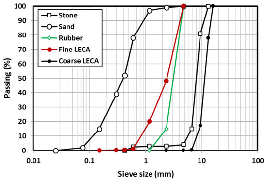
Figure 1.
Sieve analysis of the aggregates used.
Unidirectional carbon FRP sheets with a nominal thickness of 0.13 mm and two-part epoxy resins were used to confine the specimens produced to test the concrete joints in columns subjected to axial compression. According to the manufacturer’s data, the ultimate strength, elastic modulus, and failure strain were 4900 MPa, 230 GPa, and 2.1%, respectively, for the carbon FRP sheets, and 30 MPa, 4.5 GPa, and 0.9%, respectively, for the epoxy resin. Five N8.6@100mm spacing bars were used as steel reinforcements for the specimens (L-shape) produced to test the slab–beam joints in concrete slabs under bending. N8 steel shear connectors were used in some L-shaped specimens. The reinforcement bars had a yield strength of 550 MPa, yield strain of 0.00275, and elastic modulus of 200 GPa.
2.2. Mix Designs and Mixing Procedure
Four concrete mixes were designed with similar axial strengths of 32 MPa, including CC, GR, GL, and RECC mixes. For the GR mix, 20% of its fine aggregate volume was rubber; for the GL mix, 100% of its fine aggregate volume was fine LECA and 5% of its coarse aggregate volume was coarse LECA; and for the RECC mix, 100% of its fine aggregate volume was rubber. The design of the four mixes is shown in Table 2. The concrete compressive strength reported in Table 2 was measured by testing two 100 × 200 mm cylinders taken from each mix.
Table 2.
Concrete mix design (kg/m3).
The mixing procedure for all mixes started by mixing dry aggregates, adding water/activator, and mixing again before adding the remaining ingredients and mixing them all together for at least 2 min. In the RECC mix, the fiber was added gradually while mixing to ensure good fiber dispersion within the concrete matrix.
2.3. Specimen Preparation and Test Procedures
In this study, Eco-Con mixes with 32 MPa compressive strength were utilized as simulated ‘repair’ materials in several types of concrete joints, namely reinforced slab–beam joints (400 × 300 mm L-shaped, 500 mm width, and 100 mm thickness) subjected to bending, concrete joints in beams (100 × 100 × 350 mm) subjected to bending, and concrete joints in unconfined and FRP-confined columns (100 mm diameter and 200 mm height) subjected to axial compression. The reinforced slab–beam joint and FRP-confined column joint were tested with two joint angles of 0° and 45°. The mechanical properties of the proposed concrete mixes were also measured, such as unit weight, indirect tensile strength, bending strength, and shear strength.
2.3.1. Standard Test Specimens for Mechanical Properties
According to the Australian Standard (AS), two 100 × 200 mm cylinders and two 100 × 100 × 350 mm beams were prepared from each concrete mix for evaluating the indirect tensile strength and the 4-point bending strength, respectively, at 28 days of age. The concrete shear strength was measured by preparing two double-L specimens from each mix with external dimensions of 100 × 100 × 200 mm and testing them under axial compression at 28 days of age, as shown in Figure 2. The double-L specimens were prepared by casting full columns with 100 × 100 × 200 mm dimensions and creating reverse grooves 50 mm apart within the middle third of each specimen using a concrete saw (see Figure 2a). This resulted in a shearing area of 50 × 100 mm in each specimen. A loading rate of 0.8 kN/s was used in the indirect tensile strength test and the shear strength test, and a loading rate of 0.06 kN/s was used in the 4-point bending test.
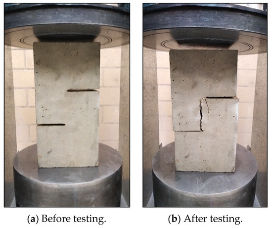
Figure 2.
Concrete shear strength test specimens.
2.3.2. Reinforced Slab–Beam Concrete Joint Subjected to Bending
Ten L-shaped specimens were prepared for testing the reinforced concrete slab–beam joint under bending. The L-shape had dimensions of 300 × 400 mm, 500 mm width, and 100 mm thickness. Each specimen was reinforced with 5N8.6 main bars (0.58% reinforcement ratio) in the direction of the applied bending moment. Table 3 and Figure 3 show the details, geometry, and reinforcement of the tested specimens that were designed according to AS 3600 [33]. Each L-shaped (300 × 400 mm) specimen was prepared in two steps; the 400 mm part (simulating the slab needing rehabilitation), then the 300 mm part (simulating the existing beam). The 400 mm part was cast first from Eco-Con and was cured in a wooden form for 48 h. The 300 mm part was then cast from CC mix and was cured in a wooden form for another 48 h before the whole specimen was demolded and cured for 28 days by soaking in a water bath. Before soaking the whole specimen in the water bath, the concrete of each part was cured by covering it using a plastic sheet and showering in water it twice a day. The reinforced concrete slab–beam joint was tested with two angles, 0° and 45°; two similar specimens were prepared from each concrete mix, one with 0° and another with 45°. This resulted in eight L-shaped specimens for the four concrete mixes. Another two specimens were prepared to join GL and CC mixes, but with steel shear connectors. The shear connectors were 4N8 bars with a length of 160 mm and embedded vertically in one specimen with a 0° joint angle and inclined in one specimen with a 45° joint angle. The shear connectors were aligned with the geometrical centerline of the joints and embedded symmetrically around the joint interface. The concrete joint angles (0° or 45°) were considered and prepared when casting the first part of each specimen, as shown in Figure 3. Using a 100 kN capacity hydraulic jack (stroke of 300 mm), the slab–beam joints were monotonically tested with a loading rate of 5 kN/min. The specimens were fixed to the strong floor from the beam side (300 mm) using a rigid beam, as shown in Figure 3. Each specimen was instrumented with one LVDT positioned at the end of the cantilever slab mid-span to measure its deflection. A load cell with 50 kN capacity was used to measure the load on the specimens during testing. LABVIEW 8.6 [34] and a data acquisition system were employed to control and record the testing and measurements of the specimens.
Table 3.
Details of all concrete joint specimens.
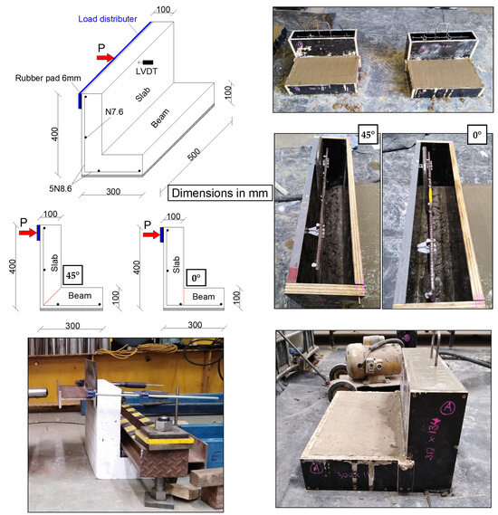
Figure 3.
Preparation and testing of reinforced concrete slab–beam joint subjected to bending.
2.3.3. Concrete Joint in Beams Subjected to Bending
The performance of concrete joints in beams subjected to 4-point bending was measured by preparing two small-scale beams (100 × 100 × 350 mm beams per variable) with two halves of concrete (bottom and top). The bottom was made of Eco-Con mixes and was the simulated part of the beam needing repair. The top one was made of the CC mix and was used to simulate the existing part of the beam needing repair. While casting the concrete, the bottom half was poured first and cured for 48 h in the casting place (steel mold) by covering it using a plastic sheet and continuously showering it with tap water. The top half was then poured and cured in the mold for another 48 h before the whole specimen was demolded and cured for 28 days in a water bath. Table 3 and Figure 4 show the details, preparation, and testing of the concrete joints in the beams. A loading rate of 0.06 kN/s was used to carry out the 4-point bending test.
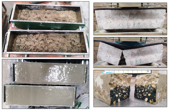
Figure 4.
Preparation and testing of concrete joints in beams subjected to bending.
2.3.4. Concrete Joints in Columns Subjected to Axial Compression
For the concrete joints in columns, unconfined and FRP-confined concrete cylinders of 100 × 200 mm were prepared for testing under axial compression, as shown in Figure 5. A total of 20 cylindrical specimens were prepared for that test, including eight unconfined specimens with a 0° concrete joint angle, eight unconfined specimens with a 45° concrete joint angle, and four FRP-confined specimens with a 45° concrete joint angle, see Table 3. The 0° joint angle was selected to simulate the typical angle in columns with repaired segments, and the 45° joint angle was selected because it applies the highest shear stresses at the joint interface’s surface. Each specimen was cast in a steel mold in the form of two halves (bottom and top). The bottom halves (simulating the existing part of the column) were all prepared from CC mix, first as full concrete cylinders that were left for 48 h to cure; then, each cylinder was cut into two halves using a concrete saw to prepare half-cylinders with 0° cuts and half-cylinders with 45° cuts. The prepared concrete half-cylinders were then placed at the bottom of steel molds and then Eco-Con concrete mixes were poured to form the top half (simulating the repaired part of the column) of the specimens and cured for another 48 h before the whole specimens were demolded and cured in a water bath for 28 days. The ends of all cylinder specimens were ground according to AS 1012.9 [35]. All specimens were tested under axial compression with a constant loading rate of 20 MPa/min using a compression machine (1500 kN capacity).
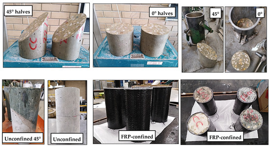
Figure 5.
Preparation of unconfined and FRP-confined concrete joints in columns subjected to axial compression.
3. Experimental Results and Discussion
In this research, Eco-Con’s performance was experimentally investigated in concrete joints with several structural elements. The indirect tensile strength, bending strength, and shear strength were measured to investigate the mechanical properties of the 32 MPa Eco-Con mixes. The tested concrete joints were reinforced slab-beam concrete joints subjected to bending, concrete joints in beams subjected to bending, and concrete joints in unconfined and FRP-confined columns subjected to axial compression. The following sections present the results of the measured mechanical properties and the structural performances.
3.1. Mechanical Properties
Table 4 shows the measured mechanical properties of the four 32 MPa Eco-Con mixes in this study. Compared with the CC mix, all Eco-Con mixes showed relatively less unit weight by 9%, 17%, and 21%, respectively, for the GR, GL, and RECC mixes, as shown in Figure 6a. This was due to the existence of high volumes of lightweight aggregates, like LECA and rubber, in these mixes.
Table 4.
Measured mechanical properties of the concrete mixes.
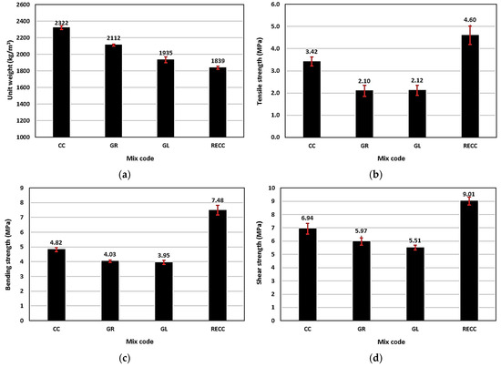
Figure 6.
Mechanical properties of the Eco-Con mixes: (a) unit weight, (b) indirect tensile strength, (c) bending strength, and (d) shear strength.
The geopolymer Eco-Con mixes showed indirect tensile strengths less than those of the CC mix; however, the RECC Eco-Con mix showed relatively higher indirect tensile strength, as shown in Figure 6b. The GR mix showed an indirect tensile strength that was 39% lower than that of the CC mix. This can be attributed to the increase in the number of weak points when using rubber in the GC matrix that became pronounced because of the well-known poor adhesion of rubber to a binder; hence, this resulted in tensile crack formation under loading [36]. The indirect tensile strength of the GL mix was 38% less than that of the CC mix. This was due to the relative weakness of LECA particles compared with natural concrete aggregates, which caused the easy splitting of the aggregate under tensile stress, especially when using a high volume of LECA. Although the RECC mix had a high content of rubber, it showed an indirect tensile strength 35% higher than that of the CC mix. This was due to the presence of fibers in the RECC mix that resisted crack formation and development, which resulted in relatively higher tensile strength. For the same reason, the RECC mix showed an indirect tensile strength that was 2.2 times and 2.1 times the indirect tensile strength of the GR and GL mixes, respectively.
Similar to the indirect tensile strength, the bending strengths of the GR and GL mixes were 16% and 18% lower than that of the CC mix, as shown in Figure 6c. This was due to the strong correlation between the concrete’s tensile and bending strengths. Concrete’s bending strength is a function of its compressive strength (in the compression zone) and tensile strength (in the tension zone). The compressive strength of all mixes in this study was constant, at 32 MPa; therefore, the tensile behavior that depended on the concrete mix ingredients controlled the concrete’s bending behavior. Due to the high volume of fibers used in the RECC mix, it showed significantly better bending strength than the CC mix by 55%. For the same reason, the RECC mix showed 86% and 89% higher bending strength than the GR and GL mixes, respectively.
Figure 6d displays the measured direct shear strengths of all mixes determined using the double-L specimens. The geopolymer Eco-Con GR and GL mixes showed 14% and 21% lower shear strength than the CC mix, respectively. This was due to the rubber or LECA aggregates’ weakness in resisting direct shear forces compared with natural concrete sand. The RECC Eco-Con mix exhibited a direct shear strength that was 1.3 times that of the CC mix. This was attributed to the effectiveness of the PP fibers in increasing the shear resistance of concrete. For the same reason, the RECC mix showed a direct shear strength that was 1.5 times and 1.6 times the direct shear strengths of the GR and GL mixes, respectively.
3.2. Reinforced Slab–Beam Concrete Joint under Bending
3.2.1. Test Observations and Failure Mode
The failure mode, crack extension, and global damage of all slab–beam joints are shown in Figure 7. For the specimens made with slabs from the CC mix, at loads of 15 kN for specimen L1 and 14 kN for specimen L2, flexural cracks initiated in the slabs at a 100 mm strip from the shared zones (100 × 100 × 500 mm shared zones between the slabs and the beams). With continuous loading, the cracks propagated toward the shared zones until clear failure occurred at the joint interfaces (0° for specimen L1 and 45° for specimen L2). Similar behaviors were observed for the specimens produced with slabs from the GR or GL mixes. At loads of 9 kN for specimen L3, 13 kN for specimen L4, and 8 kN for both specimens L5 and L6, the flexural cracks initiated in the slabs. In specimen L3, the cracks initiated at 100 mm stripped out of the shared zone, and with continuing loading, the cracks propagated toward the shared zone until a typical failure occurred at the joint’s interface (0°). In specimens L4, L5, and L6, the cracks initiated close to the joints’ interfaces and extended through the shared zones, as well as the 100 mm strip in the slab side from the shared zone with continuing loading, until a typical failure occurred at the joints’ interfaces (0° for L5 and 45° for both L4 and L6). For specimens with slabs produced from the RECC mix, at a load of 10 kN for both specimens L7 and L8, minor flexural cracks were initiated in the slabs at the 100 mm strip from the shared zones. With continuous loading, tensile cracks initiated and propagated in the beams away from the joints’ interfaces, which was the mode of failure for both specimens L7 and L8. This mode of failure occurred due to the relatively high tensile and bending strengths of the RECC mix (slabs part) and the good bond between RECC and CC mixes at the joints’ interfaces. This caused tensile failure in the beams (CC mix), rather than tensile or bending failures close to the joints’ interfaces.
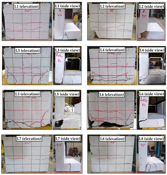
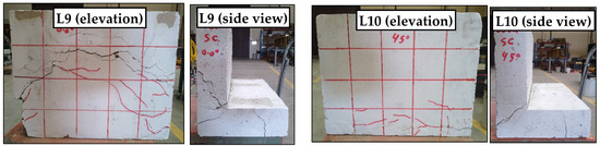
Figure 7.
Failure mode, crack extension, and global damage of the slab–beam joints subjected to bending.
The inclusion of shear connectors in specimens L9 and L10 slightly changed the failure locations compared with the corresponding specimens L5 and L6, respectively. Similar to specimens L5 and L6, at a load of 8 kN, flexural cracks initiated in the slabs in a 200 mm strip from the shared zones at 200 mm specimen L9 and in a 100 mm strip for specimen L10. With continuous loading, the cracks propagated until complete failure occurred. In specimen L9, bending failure at 190 mm in the slab part from the shared zone with a high number of cracks was the mode of failure. In specimen L10, the main crack occurred at the shared zone close to the joint’s interface.
3.2.2. Main Characteristics
Table 5 shows the results of the bending test on reinforced slab–beam joints. Figure 8 shows the main characteristics of the tested slab–beam joints. In concrete mixes with 32 MPa axial strength, using different mix ingredients affected the performance of the tested concrete slab–beam joints. At any joint angle (0° or 45°), all specimens made with Eco-Con mixes showed relatively lower strength than the specimens made from the CC mix, as shown in Figure 8a,b). This might be attributed to the adhesion incompatibility between the CC (simulating the existing beam) and the geopolymer Eco-Con (simulating the new slab), which caused failure earlier. The RECC mix showed very good adhesion with the CC mix when tested in a slab–beam joint due to the fiber’s presence, as shown in its failure mode (Figure 7). However, it did not improve the joint’s strength capacity due to the tension failure that occurred in the beam side, rather than at the joint location. At a 0° joint angle, specimens L3 (GR), L5 (GL), and L7 (RECC) showed strength capacities of 17%, 11%, and 14% lower than that of specimen L1 (CC), respectively, as shown in Figure 8a. The strength reduction reported when using Eco-Con mixes in joints with a 45° joint angle was lower than that of joints with a 0° joint angle. This might be attributed to the larger contact area at the interface between the slab and the beam when applying a 45° joint angle (contact area of 141.4 × 500 = 70,700 mm2) than that when applying a 0° joint angle (contact area of 100 × 500 = 50,000 mm2), resulting in a 41% larger contact area. At a 45° joint angle, specimens L4 (GR), L6 (GL), and L8 (RECC) showed strength capacities of 5%, 7%, and 1% lower than that of specimen L2 (CC), respectively, as shown in Figure 8b.
Table 5.
Results of reinforced slab–beam joint under bending.
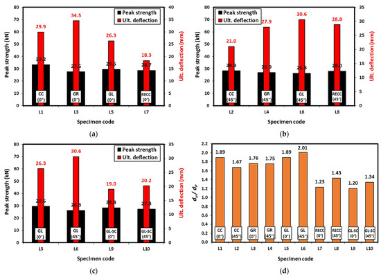
Figure 8.
Measurements of the slab–beam joints subjected to bending: (a) specimens with 0° joint angle, (b) specimens with 45° joint angle, (c) specimens with shear connectors, and (d) du/dp ratios for all specimens.
The ultimate deflection performance of the slab–beam joints made with Eco-Con mixes was different from their corresponding strength performance. At a 0° joint angle, specimen L3 (GR) showed ultimate deflection that was 15% higher than that of specimen L1 (CC); however, specimens L5 (GL) and L7 (RECC) showed ultimate deflections that were 12% and 39% less than that of specimen L1 (CC), respectively, as shown in Figure 8a. At a 45° joint angle, all specimens made with Eco-Con mixes showed relatively higher ultimate deflections than that of the specimen made with CC. Specimens L4 (GR), L6 (GL), and L8 (RECC) showed ultimate deflections that were 33%, 46%, and 37% higher than that of specimen L2 (CC), respectively, as shown in Figure 8b. The effectiveness of Eco-Con in enhancing the ultimate deflection capacity of the slab–beam joints made with a 45° joint angle might be attributed again to the larger contact area at the old/new concrete interface that allowed these concrete types to better contribute to the joint performance.
The effect of using steel shear connectors in the slab–beam joints was measured in specimens L9 (0° joint angle) and L10 (45° joint angle) made of a GL concrete slab and CC concrete beam. Figure 8c shows the performance of these specimens compared with the performances of the corresponding specimens (L5 and L6) with no shear connectors. As shown in the figure, regardless of the value of the joint angle, using shear connectors did not have any significant effect on the specimen strength capacity, as the reported strength difference was ±4%. This was attributed to the failure mode of the specimens, which was more bending failure, rather than shear failure, which depended mainly on the specimens’ main reinforcement (see Figure 7). It should be noted that the shear connectors were aligned with the geometrical centerlines of the joints and did not contribute well to the tension capacity of the joint. On the other hand, the existence of the shear connectors over-reinforced the specimens at the joint locations which increased their stiffness; hence, relatively lower ultimate deflection capacities were observed. Specimens L9 and L10 showed ultimate deflections that were 28% and 34% lower than those of the corresponding specimens L5 and L6, respectively.
Table 5 and Figure 8d display the ratio of the ultimate displacement (du) to the displacement at peak strength (dp) of all slab–beam joints. As shown in the figure, the GC mixes showed similar du/dp ratios to those of the CC mixes at both 0° and 45° joint angles. However, the RECC mixes showed 35% (at 0° joint angle) and 14% (at 45° joint angle) lower du/dp ratios than those of the CC mixes. This indicates the similar ductility of GC in general. The apparent relatively lower ductility of RECC, although it contained a high content of fiber, was attributed to the failure mode of the tested specimens (L7 and L8), in which tension failure occurred in the beam part, rather than the joint interface, as shown in Figure 7. The use of shear connectors in that type of slab–beam joint resulted in the du/dp ratio decreasing by 33–37%, regardless of the joint angle value. This was attributed again to the over-reinforcement of the specimens due to the use of the shear connectors and their marginal contribution to the tension capacity of the joints, which increased their stiffness, rather than their ductility.
As per the above results, the RECC mix showed less cracking and damage among all applied mixes. Using shear connectors in slab–beam joints had an adverse effect on concrete cracking, strength, and deformability. A joint angle of 45° was better than an angle of 0° in benefiting from the deformability of the Eco-Con mixes tested in this study. However, no significant effect was observed on the joint strength when using Eco-Con mixes instead of CC.
3.2.3. Load-Deflection Behavior
Figure 9 plots the load versus deflection of the tested slab–beam joints. As shown in Figure 9a, at a 0° joint angle, the stiffness of the specimens composed of Eco-Con mixes was lower than that of the specimen composed of the CC mix due to their relatively earlier cracking time and high number of cracks formed while loading. Of specimens L3, L5, and L7, specimen L5 (composed of GL mix) showed relatively higher stiffness than the other specimens. The stiffness degradation in specimen L3 (composed of GR mix) was smoother than that in all other specimens tested at a 0° joint angle after reaching its peak load. As shown in Figure 9b, at a 45° joint angle, the stiffness of the specimens composed of Eco-Con mixes (except specimen L8) was lower than that of the specimen composed of the CC mix due to their relatively earlier cracking time and higher number of cracks formed while loading. Specimen L8 (composed of RECC mix) showed very similar stiffness to that of specimen L2 (composed of the CC mix) until they reached their peak loads. The stiffness degradation in specimens L4 and L6 was smoother than that in all other specimens tested at a 45° joint angle after reaching the peak load. The inclusion of shear connectors in specimens L9 and L10 did not affect the specimen stiffness under loading until they reached their peak load, compared with the corresponding specimens L5 and L6, respectively. However, the stiffness degradation in the specimens without shear connectors was much smoother than that in specimens with shear connectors after reaching the peak load, regardless of the joint angle value, as shown in Figure 9c,d.
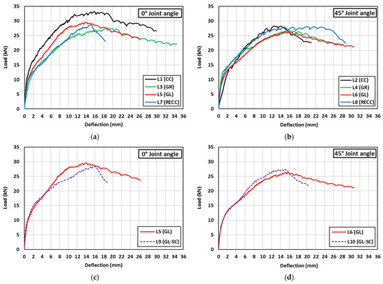
Figure 9.
Load-deflection behavior of the tested slab-beam joints under bending: (a) specimens with 0° joint angle and no SC, (b) specimens with 45° joint angle and no SC, (c) specimens with 0° joint angle and SC, and (d) specimens with 45° joint angle and SC.
At a 0° joint angle, specimens L1, L3, L5, and L7 resisted loads until crack formation occurred in the slabs at about 15 kN load and 1.4 mm deflection for L1, 9 kN load and 1.0 mm deflection for L3, 8 kN load and 0.5 mm deflection for L5, and 10 kN load and 0.9 mm deflection for L7. This was followed by a reduction in the specimens’ stiffness, and then they were able to resist more loads (the loads kept increasing) until the deflections approached about 15.8 mm at a peak load of 33.2 kN for L1, 19.6 mm at a peak load of 27.5 kN for L3, 13.9 mm at a peak load of 29.5 kN for L5, and 14.9 mm at a peak load of 28.7 kN for L7. The complete failure of the specimens occurred at 26.6 kN load and 29.9 mm deflection for L1, 22.0 kN load and 34.5 mm deflection for L3, 23.6 kN load and 26.3 mm deflection for L5, and 23.0 kN load and 18.3 mm deflection for L7. Compared with all specimens produced with a 0° joint angle and no shear connectors, specimen L7 showed relatively steep load degradation after reaching its peak load, as shown in Figure 9a.
At a 45° joint angle, specimens L2, L4, L6, and L8 resisted loads until crack formation occurred in the slabs at about 14 kN load and 3.0 mm deflection for L2, 13 kN load and 1.2 mm deflection for L4, 8 kN load and 0.5 mm deflection for L6, and 10 kN load and 0.8 mm deflection for L8. This was followed by a reduction in the specimens’ stiffness, and they resisted more loads until the deflections approached about 12.6 mm at a peak load of 28.3 kN for L2, 15.9 mm at a peak load of 26.9 kN for L4, 15.2 mm at a peak load of 26.3 kN for L6, and 20.2 mm at a peak load of 28.0 kN for L8. The complete failure of the specimens occurred at 22.6 kN load and 21.0 mm deflection for L2, 21.5 kN load and 27.9 mm deflection for L4, 21.1 kN load and 30.6 mm deflection for L6, and 22.4 kN load and 28.8 mm deflection for L8. Compared with all specimens produced with a 45° joint angle and no shear connectors, specimen L2 showed relatively steep load degradation after reaching its peak load, as shown in Figure 9b.
The inclusion of shear connectors in the specimens composed of GL slabs did not result in a significant change in the load-deflection behavior up to the specimens’ peak load compared with the corresponding specimens with no shear connectors. However, the shear connectors caused relatively steep load degradation for the specimens after reaching their peak loads, regardless of the joint angle value. Specimens L9 and L10 resisted loads until crack formation occurred in the slabs at about 8 kN load for both specimens and 0.4 mm and 0.6 mm deflections, respectively. This was followed by a reduction in the specimens’ stiffness, and they resisted more loads until the deflections approached about 15.8 mm at a peak load of 28.4 kN for L9 and 15.1 mm at a peak load of 27.3 kN for L10. The complete failure of the specimens occurred at 22.7 kN load and 19.0 mm deflection for L9 and 21.8 kN load and 20.2 mm deflection for L10.
As per the above measurements, Eco-Con exhibited similar load-deflection behavior to that of CC with similar or lower stiffness when tested in slab–beam joints. Eco-Con showed a smoother post-peak load than that of CC, especially with a 45° joint angle and with no shear connectors.
3.2.4. Toughness
The toughness of the tested specimens was determined as the area under the load-deflection curves. The toughness of each slab–beam joint specimen is presented in Table 5 and Figure 10. At 0° joint angle, using Eco-Con in slab–beam joints decreased their measured toughness; however, at 45° joint angle, their toughness increased when using Eco-Con compared with that of the corresponding CC. This was due to the larger contact area at the old/new concrete interface when using a 45° joint angle, which allowed the Eco-Con to better contribute to the joint load-deflection performance, and hence resulted in better toughness. At a 0° joint angle, specimens L3 (GR), L5 (GL), and L7 (RECC) showed toughnesses that were 6%, 23%, and 53% lower than that of specimen L1 (CC), respectively. At a 45° joint angle, specimens L4 (GR), L6 (GL), and L8 (RECC) showed toughnesses that were 34%, 43%, and 50% higher than that of specimen L2 (CC), respectively.
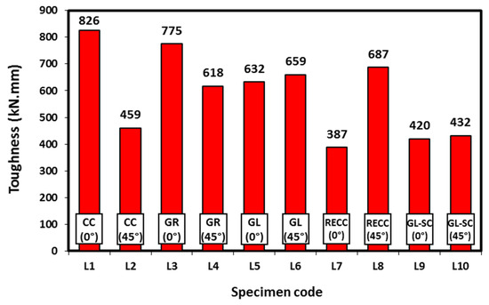
Figure 10.
Toughness of the tested slab–beam joints subjected to bending.
Figure 10 also shows the effect of using shear connectors in the slab–beam joints on joint toughness. As shown in the figure, regardless of the value of the joint angle, using shear connectors significantly decreased the joint toughness by about 35%. This was attributed to the early failure of specimens produced with shear connectors that resulted in significantly lower measured ultimate deflections and, hence, lower calculated toughness. As per the toughness measurements, the performance of Eco-Con was significantly better than that of CC when using a 45° joint angle in slab–beam joints. However, using a 0° joint angle and/or shear connectors adversely affected the joint toughness.
3.3. Concrete Joint in Beams under Bending
The performance of concrete joints in beams under four-point bending was measured using 100 × 100 × 350 mm beams produced with two halves of concrete (bottom and top). The bottom half was cast from an Eco-Con mix and the top half was cast from the CC mix, as shown in Figure 4. The failure mode of the tested concrete joints in beams using different Eco-Con mixes is shown in Figure 11. As shown, there was no evidence of failure or separation at the concrete joint interface in all tested specimens; however, they showed typical bending failure, with cracks initiated in the tension zone (bottom half) and extended to the compression zone (top half). All concrete joint specimens were broken into two separate pieces (right and left), except for the concrete joint produced with RECC mix as the bottom half and CC mix as the top half. This was due to the fibers used in the RECC mix that kept the concrete intact at the main crack location, even after failure occurred.
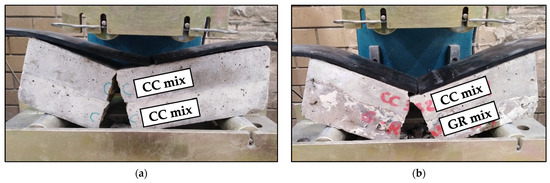
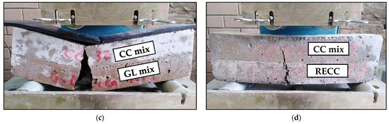
Figure 11.
Failure mode of the tested concrete joints in beams subjected to bending: (a) CC/CC, (b) CC/GR, (c) CC/GL, and (d) CC/RECC.
Table 6 and Figure 12 show the results of the tested concrete joints under bending. Similar to the bending strength behavior of Eco-Con mixes (see Figure 6c), the concrete joints produced with bottom halves of GR (specimens B3 and B4) and GL (specimens B5 and B6) mixes showed average bending strengths that were 14% and 36% lower than that of the concrete joints produced with the CC mix (specimens B1 and B2), respectively. Consequently, the concrete joints produced with RECC mix as the bottom half (specimens B7 and B7) showed an average bending strength that was 43% higher than that of concrete joints produced with the CC mix. This was due to the factors affecting the concrete bending strength, which is a function of its compressive strength (compression zone—top half) and tensile strength (tension zone—bottom half). As all concrete joints in beams were produced with the CC mix in the top half of the beam, the joint behavior depended mainly on the tensile/bending strength of the bottom half. The use of RECC mix in the concrete beam joint showed a joint average bending strength that was 1.67 and 2.24 times higher than those of the joints produced with GR and GL mixes, respectively. This indicated the superiority of RECC in repairing concrete beams subjected to bending load.
Table 6.
Results of concrete joints in beams subjected to bending.
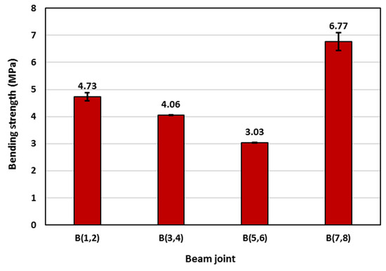
Figure 12.
Average bending strengths of the tested beam joints.
3.4. Concrete Joints in Columns Subjected to Axial Compression
The performances of concrete joints in columns under axial compression were measured on unconfined and FRP-confined concrete cylinders with dimensions of 100 × 200 mm and joint angles of 0° and 45°, as shown in Figure 5 and detailed in Table 3. Each specimen was produced with two halves; one consisting of the CC mix and the other consisting of an Eco-Con mix. The failure modes of the tested concrete joints in unconfined and FRP-confined columns composed of different Eco-Con mixes are shown in Figure 13, Figure 14 and Figure 15. As shown in Figure 13, there was no evidence of failure or separation at the concrete joint interface in all tested unconfined columns with a 0° joint angle; however, they showed typical compression failure with vertical cracks that initiated and propagated through both halves of each column. Similar failure modes were observed in all tested unconfined columns with a 45° joint angle, except for the column specimens produced with ↓GL-↑CC mixes (specimens C13 and C14), in which, at the ultimate column capacity, full separation occurred between the two halves of the column with concrete crashing at the joint interface tip, as shown in Figure 14. As the FRP fibers were oriented only in the hoop direction of the column specimens, the mode of failure of all FRP-confined columns with a 45° joint angle was the vertical rupture of the FRP tube at a height of 50–120 mm in the Eco-Con halves of the tested columns, as shown in Figure 15. Failure was also accompanied by a loud snapping sound. The largest ruptured height of the FRP tube was observed in the column specimen produced with ↓RECC-↑CC mixes, which indicated the ability of RECC to efficiently utilize the tensile capacity of the FRP (this is also confirmed by the axial capacity of specimen C20).
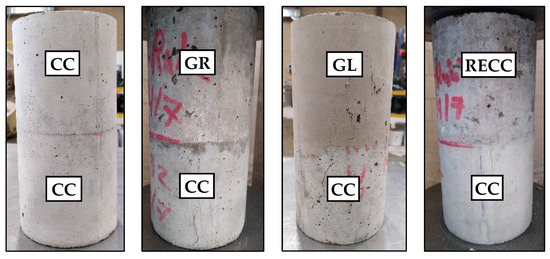
Figure 13.
Failure mode of 0° concrete joint in unconfined columns subjected to axial compression.
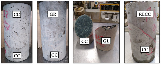
Figure 14.
Failure mode of 45° concrete joint in unconfined columns subjected to axial compression.
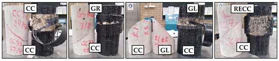
Figure 15.
Failure mode of 45° concrete joint in FRP-confined columns subjected to axial compression.
Table 7 and Figure 16 show the results of the tested concrete joints in columns under axial compression. As mixes in this study had 32 MPa axial strength, all tested joints in unconfined columns showed axial compression capacity similar to the concrete compressive strength (32 MPa), with slight differences ranging between −3 MPa and +1.3 MPa, regardless of the joint angle (0° and 45°) used. This reflected the ability of Eco-Con mixes to work efficiently in repairing unconfined concrete columns. The FRP confinement significantly enhanced the axial capacity of 45° column joints by 2.8, 2.7, 2.6, and 2.9 times for column joints C(3,4), C(8,9), C(13,14), and C(18,19), respectively (see the confinement effectiveness in Table 7). Compared with column specimens C(3,4), made of ↓CC-↑CC mixes, using GR and GL mixes in FRP-confined column joints decreased the column axial capacity by 11% and 14%, respectively; however, using RECC mix increased the column axial capacity by 2%. This might be due to the relatively low tensile strength of Eco-Con mixes GR and GL that caused the earlier crushing of concrete at the FRP/concrete interface, and hence, earlier rupture of the FRP-contained tubes. On the other hand, the RECC mix had relatively higher tensile strength than that of the CC mix, with delayed crack initiation due to the presence of rubber and fibers, which resulted in the utilization of the FRP tensile capacity with higher efficiency. For the same reason, specimen C20 showed an axial capacity that was 14% and 19% higher than those of specimens C10 and C15, respectively. The results of the tested column joints indicated the superiority of RECC in repairing concrete columns subjected to axial compression.
Table 7.
Results for concrete joints in columns subjected to axial compression.
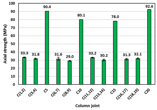
Figure 16.
Average axial strength of the tested unconfined and FRP-confined column joints.
4. Conclusions and Recommendations
In this research, GC and RECC (having a similar compressive strength of 32 MPa) Eco-Con mixes were utilized as simulated repair materials in reinforced concrete joints in slabs subjected to bending, concrete joints in beams subjected to bending, and concrete joints in unconfined and FRP-confined columns subjected to axial compression. The mechanical properties were also measured for the proposed Eco-Con mixes, such as the unit weight, indirect tensile strength, bending strength, and shear strength. The main conclusions of this experimental study can be summarized in the following points:
- Compared with the CC mix, the GC mixes showed lower indirect tensile strength, bending strength, and shear strength by up to 39%, 18%, and 21%, respectively; however, the RECC mix showed relatively higher corresponding strengths by 35%, 55%, and 30%, respectively. All Eco-Con mixes showed relatively lower unit weight by up to 21% compared with that of the CC mix. This indicated the lighter weight of the proposed Eco-Con mixes.
- The Eco-Con mixes showed similar load-deflection behavior to that of the CC mix when tested in slab–beam joints. At the tested joint angles (0° or 45°), using Eco-Con mixes achieved a relatively lower slab–beam joint strength capacity than that when using the CC mix by up to 14%. The joint angle of 45° was better than that of 0° as it showed better slab–beam joint strength capacity by up to 7%. Using shear connectors in slab–beam joints had an adverse effect on concrete cracking and deformability; in addition, they did not have any significant effects on the joint strength capacity; therefore, they should be avoided.
- Concrete joints in beams produced partially with GC mixes showed bending strengths lower than those of joints produced with the CC mix by up to 36%; however, the joints produced partially with RECC mix showed a relatively higher bending strength by 43%. This indicated the superiority of RECC in repairing concrete beams subjected to bending load.
- All tested joints in unconfined columns showed axial compression capacities similar to the concrete compressive strength (32 MPa), regardless of the joint angle (0° or 45°). The FRP confinement significantly enhanced the axial capacity of the 45° column joints by up to 2.9 times. Using GC mixes in FRP-confined column joints decreased the column axial capacity by up to 14%; however, using RECC mix increased the column axial capacity by 2%. The results of tested column joints indicated the efficiency of using RECC instead of CC in repairing concrete columns subjected to axial compression.
Overall, the RECC mix showed a better ability to repair different structural elements than all Eco-Con mixes tested in this study, and it can be recommended as an Eco-Con alternative to Portland cement concrete. This indicates the applicability of this type of lightweight Eco-Con in structures subjected to bending or axial loads. GC would be the lightweight Eco-Con to recommend in this study for structures that do not need high strength, but have a higher demand for sustainability. The results of this experimental study can provide the necessary data and information to develop Eco-Con in structural elements that need repair and rehabilitation.
It is recommended to conduct a parametric study on the applied parameters and the different properties of materials in future studies. In addition, theoretical modeling of the testing conducted is recommended to verify the results’ accuracy. More comparisons of solutions by cost-effectiveness, building duration, environmental impact, and statistics are also recommended.
Author Contributions
Conceptualization, O.Y. and R.R.; Formal analysis, O.Y. and R.R.; Funding acquisition, A.M.T.; Investigation, O.Y. and M.E.; Methodology, O.Y. and M.E.; Project administration, M.E.; Resources, A.M.T.; Software, O.Y.; Supervision, A.M.T.; Validation, O.Y.; Visualization, R.R.; Writing—original draft, O.Y.; Writing—review and editing, O.Y., R.R., M.E., and A.M.T. All authors have read and agreed to the published version of the manuscript.
Funding
This research received no external funding.
Data Availability Statement
The data presented in this study are available in the article.
Acknowledgments
The authors gratefully acknowledge the donations of the following: sand by Rocla Golden Grove Quarry, stone by Jennings Rosedale Quarry, cement by Adelaide Brighton Cement Pty. Ltd., rubber aggregate by Tyrecycle Pty. Ltd., fly ash by Fly ash Australia Pty. Ltd., ground granulated blast furnace slag by Independent Cement & Lime Pty. Ltd., super plasticizer and short polypropylene fiber by Master Builders Solution (BASF), and long polypropylene fiber by TEXO Australasia Pty. Ltd. The authors also acknowledge the contributions of Tim Golding, Michelle Plew, Rohan Muscher, Craig Sweetman, and the following Honors’ students who assisted in the experimental work reported in this paper: Anmol Haq, Saumya Garg, Durga Challa, Sachitra Arachchilage, Ritesh Neupane, Harnish Parmar, Yash Ramanuj, and Harshil Thakar.
Conflicts of Interest
The authors declare no conflict of interest.
References
- Roychand, R.; Li, J.; Kilmartin-Lynch, S.; Saberian, M.; Zhu, J.; Youssf, O.; Ngo, T. Carbon sequestration from waste and carbon dioxide mineralisation in concrete–A stronger, sustainable and eco-friendly solution to support circular economy. Constr. Build. Mater. 2023, 379, 131221. [Google Scholar] [CrossRef]
- Aslani, F.; Deghani, A.; Asif, Z. Development of Lightweight Rubberized Geopolymer Concrete by Using Polystyrene and Recycled Crumb-Rubber Aggregates. J. Mater. Civ. Eng. 2020, 32, 04019345. [Google Scholar] [CrossRef]
- Luhar, S.; Chaudhary, S.; Luhar, I. Development of rubberized geopolymer concrete: Strength and durability studies. Constr. Build. Mater. 2019, 204, 740–753. [Google Scholar] [CrossRef]
- Gomaa, E.; Gheni, A.A.; Kashosi, C.; ElGawady, M.A. Bond strength of eco-friendly class C fly ash-based thermally cured alkali-activated concrete to portland cement concrete. J. Clean. Prod. 2019, 235, 404–416. [Google Scholar] [CrossRef]
- Huntzinger, D.N.; Eatmon, T.D. A life-cycle assessment of Portland cement manufacturing: Comparing the traditional process with alternative technologies. J. Clean. Prod. 2009, 17, 668–675. [Google Scholar] [CrossRef]
- Gao, L.; Adesina, A.; Das, S. Properties of eco-friendly basalt fibre reinforced concrete designed by Taguchi method. Constr. Build. Mater. 2021, 302, 124161. [Google Scholar] [CrossRef]
- Youssf, O.; Swilam, A.; Tahwia, A.M. Performance of Crumb Rubber Concrete Made with High Contents of Heat Pre-treated Rubber and Magnetized Water. J. Mater. Res. Technol. 2023, 23, 2160–2176. [Google Scholar] [CrossRef]
- Yi, O.; Zhuge, Y.; Ma, X.; Gravina, R.; Mills, J.E.; Youssf, O. Push-off and Pull-out Bond Behaviour of CRC Composite Slabs—An Experimental Investigation. Eng. Struct. 2020, 2020, 110448. [Google Scholar] [CrossRef]
- Yacob, N.S.; ElGawady, M.A.; Sneed, L.H.; Said, A. Shear strength of fly ash-based geopolymer reinforced concrete beams. Eng. Struct. 2019, 196, 109298. [Google Scholar] [CrossRef]
- Błaszczyński, T.; Król, M. Usage of green concrete technology in civil engineering. Procedia Eng. 2015, 122, 296–301. [Google Scholar] [CrossRef]
- Diaz-Loya, E.I.; Allouche, E.N.; Vaidya, S. Mechanical properties of fly-ash-based geopolymer concrete. ACI Mater. J. 2011, 108, 300. [Google Scholar]
- Mustafa, M.; Bakri, A.; Mohammed, H.; Kamarudin, H.; Nizar, K.; Zarina, Y. Review on fly ash-based geopolymer concrete without Portland Cement. J. Eng. Technol. Res. 2011, 3, 1–4. [Google Scholar]
- Bakharev, T.; Sanjayan, J.G.; Cheng, Y.B. Sulfate attack on alkali-activated slag concrete. Cem. Concr. Res. 2002, 32, 211–216. [Google Scholar] [CrossRef]
- Ismail, I.; Bernal, S.A.; Provis, J.L.; Nicolas, R.S.; Brice, D.G.; Kilcullen, A.R.; Hamdan, S.; van Deventer, J.S.J. Influence of fly ash on the water and chloride permeability of alkali-activated slag mortars and concretes. Constr. Build. Mater. 2013, 48, 1187–1201. [Google Scholar] [CrossRef]
- Australia, T.S. Tyre Stewardship Australia. 2019. Available online: https://www.racv.com.au/membership/member-benefits/royalauto/archive/old-tyres-a-new-local-solution-to-a-global-challenge.html (accessed on 3 February 2020).
- Youssf, O.; Hassanli, R.; Mills, J.; Ma, X.; Zhuge, Y. Cyclic Performance of Steel–Concrete–Steel Sandwich Beams with Rubcrete and LECA Concrete Core. J. Compos. Sci. 2019, 3, 5. [Google Scholar] [CrossRef]
- Kewalramani, M.A.; Mohamed, O.A.; Syed, Z.I. Engineered Cementitious Composites for Modern Civil Engineering Structures in Hot Arid Coastal Climatic Conditions. Procedia Eng. 2017, 180, 767–774. [Google Scholar] [CrossRef]
- Li, V.C.; Horikoshi, T.; Ogawa, A.; Torigoe, S.; Saito, T. Micromechanics-based durability study of polyvinyl alcohol-engineered cementitious composite. Mater. J. 2004, 101, 242–248. [Google Scholar]
- Granger, S.; Loukili, A.; Pijaudier-Cabot, G.; Chanvillard, G. Experimental characterization of the self-healing of cracks in an ultra high performance cementitious material: Mechanical tests and acoustic emission analysis. Cem. Concr. Res. 2007, 37, 519–527. [Google Scholar] [CrossRef]
- Li, M. 7—Engineered cementitious composites for bridge decks. In Advanced Composites in Bridge Construction and Repair; Kim, Y.J., Ed.; Woodhead Publishing: Sawston, UK, 2014; pp. 177–209. [Google Scholar]
- Lye, H.L.; Mohammed, B.S.; Liew, M.; Wahab, M.; Al-Fakih, A. Bond behaviour of CFRP-strengthened ECC using Response Surface Methodology (RSM). Case Stud. Constr. Mater. 2020, 12, e00327. [Google Scholar] [CrossRef]
- Vasconcelos, E.; Fernandes, S.; de Aguiar, J.L.B.; Pacheco-Torgal, F. Concrete retrofitting using metakaolin geopolymer mortars and CFRP. Constr. Build. Mater. 2011, 25, 3213–3221. [Google Scholar] [CrossRef]
- Al-Majidi, M.H.; Lampropoulos, A.P.; Cundy, A.B.; Tsioulou, O.T.; Al-Rekabi, S. A novel corrosion resistant repair technique for existing reinforced concrete (RC) elements using polyvinyl alcohol fibre reinforced geopolymer concrete (PVAFRGC). Constr. Build. Mater. 2018, 164, 603–619. [Google Scholar] [CrossRef]
- Wang, Y.-S.; Peng, K.-D.; Alrefaei, Y.; Dai, J.-G. The bond between geopolymer repair mortars and OPC concrete substrate: Strength and microscopic interactions. Cem. Concr. Compos. 2021, 119, 103991. [Google Scholar] [CrossRef]
- Akbar, M.; Hussain, Z.; Huali, P.; Imran, M.; Thomas, B.S. Impact of waste crumb rubber on concrete performance incorporating silica fume and fly ash to make a sustainable low carbon concrete. Struct. Eng. Mech. 2023, 85, 275–287. [Google Scholar]
- Umar, T.; Yousaf, M.; Akbar, M.; Abbas, N.; Hussain, Z.; Ansari, W.S. An Experimental Study on Non-Destructive Evaluation of the Mechanical Characteristics of a Sustainable Concrete Incorporating Industrial Waste. Materials 2022, 15, 7346. [Google Scholar] [CrossRef] [PubMed]
- Ozbakkaloglu, T.; Idris, Y. Seismic Behavior of FRP-High-Strength Concrete–Steel Double-Skin Tubular Columns. J. Struct. Eng. 2014, 140, 04014019. [Google Scholar] [CrossRef]
- Xian, G.; Guo, R.; Li, C. Combined effects of sustained bending loading, water immersion and fiber hybrid mode on the mechanical properties of carbon/glass fiber reinforced polymer composite. Compos. Struct. 2022, 281, 115060. [Google Scholar] [CrossRef]
- Guo, R.; Xian, G.; Li, C.; Hong, B. Effect of fiber hybrid mode on the tension–tension fatigue performance for the pultruded carbon/glass fiber reinforced polymer composite rod. Eng. Fract. Mech. 2022, 260, 108208. [Google Scholar] [CrossRef]
- Nawaz, W.; Elchalakani, M.; Karrech, A.; Yehia, S.; Yang, B.; Youssf, O. Flexural behavior of all lightweight reinforced concrete beams externally strengthened with CFRP sheets. Constr. Build. Mater. 2022, 327, 126966. [Google Scholar] [CrossRef]
- Liu, J.; Sheikh, S.A. Fiber-Reinforced Polymer-Confined Circular Columns under Simulated Seismic Loads. ACI Struct. J. 2013, 110. [Google Scholar] [CrossRef]
- Youssf, O.; Hassanli, R.; Mills, J.E. Mechanical performance of FRP-confined and unconfined crumb rubber concrete containing high rubber content. J. Build. Eng. 2017, 11, 115–126. [Google Scholar] [CrossRef]
- AS 3600; Concrete Structures. Standards Australia: Sydney, Australia, 2009.
- LabVIEW User’s Manual, version 8.6; National Instruments: Austin, TX, USA, 2003.
- AS 1012.9; Methods of Testing Concrete—Compressive Strength Tests—Concrete, Mortar and Grout Specimens. Standards Australia: Sydney, Australia, 2014.
- Zheng, L.; Huo, X.S.; Yuan, Y. Strength; modulus of elasticity, and brittleness index of rubberized concrete. J. Mater. Civ. Eng. 2008, 20, 692. [Google Scholar] [CrossRef]
Disclaimer/Publisher’s Note: The statements, opinions and data contained in all publications are solely those of the individual author(s) and contributor(s) and not of MDPI and/or the editor(s). MDPI and/or the editor(s) disclaim responsibility for any injury to people or property resulting from any ideas, methods, instructions or products referred to in the content. |
© 2023 by the authors. Licensee MDPI, Basel, Switzerland. This article is an open access article distributed under the terms and conditions of the Creative Commons Attribution (CC BY) license (https://creativecommons.org/licenses/by/4.0/).