Article

Feasibility Study of Steel Derailment Containment Provisions through Quasi-Static Experiments

1
Department of Civil Engineering, Kyungnam University, Changwon 51767, Republic of Korea
2
UB E&C Co., Ltd., 42 Beolmal-ro 50 beon-gil, Bundang-gu, Seongnam 13503, Republic of Korea
3
Department of Civil Engineering, Chungnam National University, Daejeon 34134, Republic of Korea
4
Advanced Railroad Civil Engineering Division, Korea Railroad Research Institute, 176 Cheoldobangmulgwan-ro, Uiwang 16105, Republic of Korea
*
Author to whom correspondence should be addressed.
Buildings 2024, 14(1), 171; https://doi.org/10.3390/buildings14010171
Submission received: 28 November 2023 / Revised: 4 January 2024 / Accepted: 6 January 2024 / Published: 10 January 2024

Abstract

:
Railway derailments present a safety hazard, carrying the potential for severe consequences for both human lives and the economy. Implementing derailment containment provisions (DCPs) near the track centerline is essential for mitigating risks in operating high-speed rail (HSR) while providing significant advantages for the large-scale upgrade of existing railway infrastructure. Therefore, this paper investigated the feasibility of a DCP system made of steel through quasi-static experiments, aiming to enhance safety in HSR operations. Initially, single anchor tests were conducted to assess its capacity to withstand applied loads, prevent the pullout of steel anchors, and avoid the local rotation of the steel frame. Then, full-scale steel DCP systems were manufactured and tested for quasi-static load at different locations, including the mid-anchor, the mid-span, and the end-anchor. The relationship between applied load and displacement, along with the initial stiffness of the DCP specimens, was discussed. The findings revealed that the single anchor can withstand an applied load of up to 197.9 kN. The DCP specimen maintained structural integrity at the 207 kN target load under all load scenarios, showing a maximum displacement of 8.93 mm in the case of applied load at mid-span. Furthermore, the initial stiffness of the DCP systems was 1.77 to 2.55 times greater than that of a single anchor, validating a force-bearing coordination mechanism among neighboring anchors and the substantial impact of the applied load positions on their stiffness.

1. Introduction

High-speed rail (HSR) systems have risen as pioneers in advanced global transportation, crucial not only for enhancing mobility but also for exerting a profound influence on the dynamics of regional development [1,2,3]. HSR holds the potential to significantly reduce travel time, improve travel efficiency, and facilitate economic and personnel interactions across different regions and cities, playing a crucial role in promoting a sustainable economy [4]. Nevertheless, the heightened speed of rail has also brought about an augmented risk of derailments, thereby diminishing safety levels during operations [5,6]. Derailments represent the most common type of train accident, resulting in potentially catastrophic consequences for heavy loss of human life and property [7,8,9,10]. Achieving complete prevention proves unattainable due to unforeseeable factors like human error, variable weather conditions, and natural disasters [11,12,13,14]. In the face of growing demand for HSR development, finding solutions to minimize possible risks becomes increasingly essential.
Scholars worldwide have dedicated their efforts to studying post-derailment behavior and restraining lateral movements of derailed trains to minimize the consequences of derailments, resulting in notable achievements. Barbie et al. suggested employing a brake disc and a bogie frame to maintain derailed vehicles close to the track centerline after evaluating the post-derailment behavior of high-speed rail vehicles through a 3D dynamic model [15,16,17]. Kajitani et al. devised an L-shaped guide to prevent deviation in derailment accidents, and it has been incorporated across the entire Shinkansen bullet trains in Japan [18]. Sunami et al. designed a post-derailment stopper for bogie frames and proposed a 15-degrees-of-freedom vehicle dynamics model to investigate their motion under a derailment [19]. Guo et al. suggested a safety device mounted under the axle box to minimize trailer vehicle deviation in the event of derailments [20]. Wu et al. developed preventive devices to restrict the lateral displacement of derailed vehicles and verified their effectiveness through derailment experiments conducted at low speeds [21,22]. In general, these studies aimed to improve the guidance ability of vehicle component-based substitute guidance mechanisms by increasing the possibility of contact or collision between the vehicle components and the track to keep the derailed train on the railway track. Efforts to keep derailed trains near the track centerline are beneficial for minimizing damage compared to a part of or the whole train running off the rail or completely veering off the railway tracks [23]. However, the devices must be installed for each bogie in individual trains to achieve optimal safety benefits. Attaining the intended safety enhancements for the entire high-speed rail system entails substantial research and installation costs. Accordingly, the overall cost optimization has been neglected because the risk of derailment is typically associated with high-risk areas during severe weather conditions.
In contrast to the research on enhancing safety systems for individual trains, studies on developing rerouting auxiliary systems for railways in derailments are still scarce. This approach proves beneficial in improving the operational safety of large-scale railway upgrades. Nevertheless, designing an entirely new preventive system to ensure the safety of train operations is likely to be expensive and impractical in the short term, given that many countries worldwide already possess extensive rail networks, with a substantial portion being HSR [24,25,26,27]. Consequently, developing auxiliary systems for derailment-prone areas, with the capability of seamlessly integrating them into existing rail infrastructure, becomes even more urgently needed and highly feasible [28]. Recently, derailment containment provisions (DCPs) have emerged as a potential solution for HSR to reduce the consequences by redirecting and maintaining derailed trains near the track centerline. Figure 1 illustrates three commonly used concepts of DCPs in railways, namely DCP Type I, II, and III [29]. DCP Type I is positioned within the track gauge and directly interacts with the wheels during derailments, thereby functioning as guard rails [30,31,32]. Although DCP Type II has a function similar to its counterpart, Type I, it is positioned outside the tracks. DCP Type III is outside the track gauge but is prepared to absorb impact from axles or bogies rather than the wheels. In Korea, DCP Type III is mandated on railway bridges with train speeds exceeding 200 km/h to prevent collisions with the superstructure or falls from the bridge in a derailment [33].
To the best of our knowledge, no comprehensive investigations have been conducted to explore the design load, installation location, and specifications of derailment containment facilities for HSR. Moreover, there is a shortage of specific objective evidence of DCPs to validate their economic efficiency and feasibility [28]. In efforts to prevent the derailment of HSR, researchers have strived to clarify these issues, aiming to pave the way for the application of DCPs in the HSR system. Lim et al. suggested a modeling method for gravel-filled track ballast, simulating a ballast-wheel collision to study structural responses and impact forces from a derailed train [34]. Song et al. presented a theoretical approach to predict impact loads on reinforced concrete (RC) DCP Type I for HSR and proposed a simplified finite element (FE) model to assess dynamic post-derailment behavior [35]. Bae et al. carried out a full-scale train derailment test to analyze the train’s post-derailment behavior and evaluate the performance of RC DCP Type III [36]. Bae et al. also analyzed the functionality of DCP Type I by conducting a comprehensive train derailment test, suggesting an approach to estimate impact loads and assess their containment effect according to changes in the center of gravity during a collision [37]. Nevertheless, upgrading existing railway systems with DCP Types II and III requires substantial foundation structures to absorb impact loads, resulting in extended construction periods. In this scenario, DCP Type I provides a promising solution with the advantages of quality construction, economic efficiency, and faster installation using pre-fabricated components.
Additionally, given the importance and ongoing operational requirements of the existing HSR system, DCP Type I may be suitable for meeting the current demand for HSR infrastructure upgrades. While research on DCPs has yielded some achievements, further in-depth assessments are necessary to validate their effectiveness and feasibility throughout experimental tests. Moreover, employing DCPs made of steel offers numerous advantages regarding construction time and deformation compatibility with steel rail systems; however, this area has not received much attention. To fill this gap, a DCP Type I system with steel frames was manufactured and tested under lateral quasi-static loads in this study. The originality of this research is that it included a full-scale experimental test to investigate the response of a steel DCP system Type I under the operational conditions of HSR systems in South Korea or those with comparable requirements, as shown in Figure 1a.

Significance and Scope of the Study

An ongoing project is being carried out to study solutions for Korean HSR to minimize the damage caused by derailment collisions using DCP. Typically, collision/impact tests are conducted to assess both global and local responses in structures, while quasi-static/static tests are mainly employed to reveal global behavior [38]. Predicting the capacity to withstand applied loads corresponding to displacement is crucial to assessing structural safety under impact [39]. Nonetheless, conducting full-scale impact tests for DCP systems at high speeds during derailments is costly and unworkable, preventing the thorough validation of the DCP’s load-bearing capacity under adverse working conditions. Hence, the initial phase, which has already been performed, involved assessing the impact forces on the DCP for high-speed trains through collision simulations to propose design specifications for DCPs [40]. As a result, DCP Type I was found to experience a maximum impact load of 165.6 kN in the event of a derailment collision at a speed of 300 km/h on a high-speed rail curve with a radius of 3500 m. In light of these findings, the DCP was designed to assess load-bearing capacity and feasibility through quasi-static tests. In the next stage, these outcomes will play a pivotal role in proposing optimal designs for DCP members, considering factors such as size (length, width, and height), anchor methods, and type of materials, and subsequently in formulating plans for comprehensive impact tests to withstand collision derailment. Finally, an effective post-derailment safety measure for Korean high-speed trains using DCP Type I can be proposed, as shown in Figure 2.
As we know, steel is widely recognized for its reputation for reliability, which is characterized by consistent and uniform properties. Its appeal is further accentuated by the advantages of enhanced quality control and accelerated erection speed, owing to the precision achieved in factory manufacturing processes. Notably, steel structures emerge as a suitable material for impacted components like DCPs thanks to their flexibility, high ductility, and capacity for impact resistance. Another crucial factor is the deformation compatibility of rails and steel frames under varying temperature conditions, enabling them to operate effectively. This feature gains more importance when considering structures that are integrated in parallel with steel rail DCP Type I systems. The inherent characteristics of steel also contribute to maintaining the structural integrity of the DCP and enhancing its performance under dynamic conditions. As a result, promoting the development of DCP Type I made of rolled steel as a safety measure to prevent the risk of derailments is essential.
Based on the results achieved in the initial stage, the main objective of the proposed experimental study is to evaluate the global response of the steel DCP Type I system under various load location scenarios. The novelty of this study lies in presenting the relationship between the applied load and the displacement and analyzing in detail the influence of the applied load location on the initial stiffness of the DCP Type I system through a full-scale experimental test. In particular, the feasibility of the proposed design under the target load is also discussed and clarified.

2. Experimental Program

2.1. Steel DCP System Details

The steel DCP frame was designed to endure derailment collisions following the guidelines established by Korean researchers, as outlined in the report on the facility development for rail vehicle deviation protection, which was approved by the Ministry of Land, Infrastructure, and Transport of the Korean government [40]. These specimens were employed in experimental investigations to examine their responses under quasi-static loading conditions. The DCP height, proposed through preliminary analysis for high-speed vehicles operated by the Korea Railway Corporation, consists of a 100 mm steel frame, a 20 mm fixed base plate, and a 5 mm insulating rubber sheet. Figure 3a shows the configuration of the steel DCP frame, constructed using assembled modules, with each module measuring 3710 mm in length. The longitudinal beams were crafted from hot-rolled standard rectangular sections measuring 150 × 100 × 9 mm. The steel braces used were of the same section as the longitudinal beam, with a length of 200 mm. Specific dimensions of the fixed base plate, frame fixture, and fixed wedge are referred to in Figure 3c,d. The design compressive strength of the RC sleepers after 28 days was 50 MPa. The yield stress of the steel frame, fixed base plate, frame fixture, and fixed wedge was 355 MPa, with an elastic modulus of 210 GPa.
Each module of the DCP served the purpose of averting the derailing of a cluster consisting of seven sleepers. The DCP was attached to the sleepers at three positions: the middle anchor and two anchors at both ends. First, for each anchor position, epoxy resin was employed to secure bolts with a 20 mm diameter to the sleepers, each having an anchor length of 90 mm. Next, the sleeper was attached to a fixed base plate and insulation pad using two side fixing nuts. Subsequently, the steel DCP frame was attached to each base plate with four corner bolts. Finally, a frame fixture and fixed wedges were employed to firmly fasten the DCP frame, base plate, and sleeper in place, as shown in Figure 4.

2.2. Single Anchor Testing

The impact of load on the displacement of single steel anchors was investigated. Figure 5 displays the load applied to the steel DCP frame at the anchor position. The anchor structure was designed similarly to the anchor in the DCP system. Accordingly, it was employed to evaluate the load-bearing capacity of an individual anchor and the corresponding displacement of the tested specimens. We utilized four linear variable displacement transducers (LVDTs) to measure horizontal and vertical displacements. The average of LVDTs H1 and H2 was employed to measure horizontal displacement (H), while LVDTs V1 and V2 were used for vertical displacements (V). Each case was duplicated, with the first and second tests denoted by the suffixes “−1” and “−2”, respectively. As shown in Figure 5a, LVDTs with an accuracy level of 0.001 mm were attached around the specimen to measure vertical and horizontal deformations within the gauge length of 100 mm during the single anchor tests, while the load data were measured by the load cell of a universal testing machine (UTM). The tests were conducted at a constant loading rate of 2 mm/min, utilizing a UTM with a capacity of 500 kN.

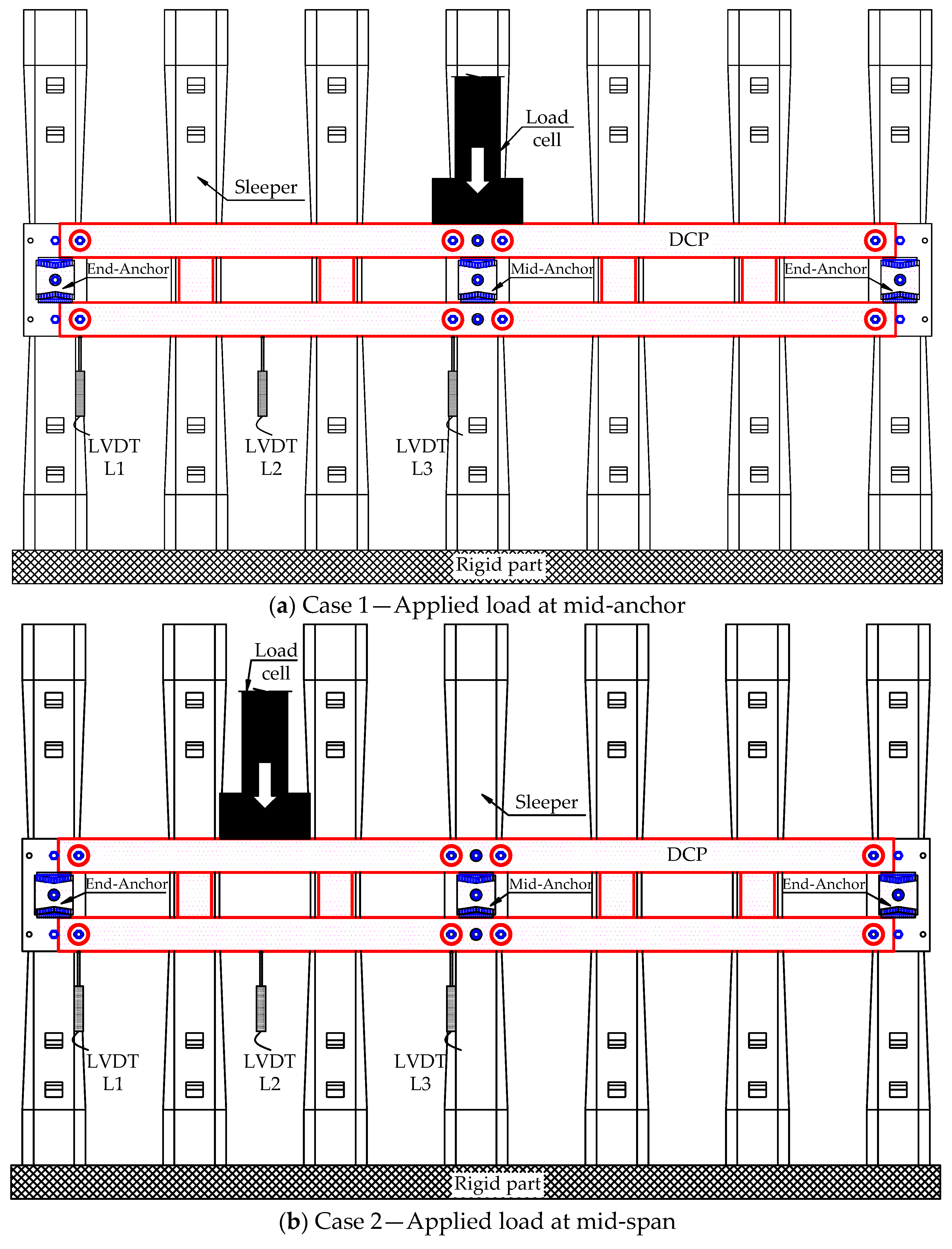
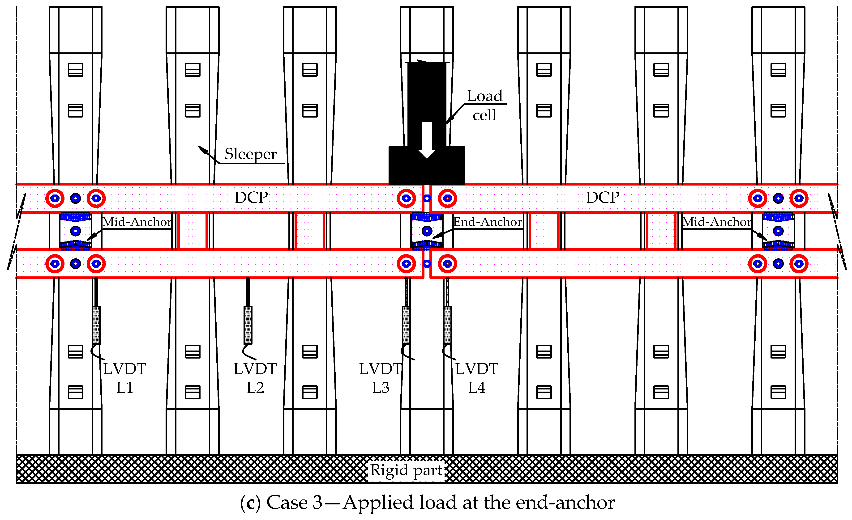
2.3. Steel DCP System Testing

Figure 6 shows the general view of the steel DCP system used in the experimental test, providing a brief overview of its components and design. We divided the steel DCPs into three groups, each designated for quasi-static load testing at different locations: the mid-anchor (referred to as Case 1), the mid-span (Case 2), and the end-anchor (Case 3). We positioned the LVDTs using the load location scenarios corresponding to specific configurations. For Cases 1 and 2, LVDTs L1, L2, and L3 were placed at the end-anchor, mid-span, and mid-anchor, as shown in Figure 7a,b. In Case 3, LVDTs L1 and L2 were placed at the mid-anchor and mid-span, respectively, while LVDTs L3 and L4 were situated on both sides of the end-anchor, as depicted in Figure 7c. In addition, the rigid part employed to secure sleepers serves a role analogous to that of steel rails in a railway system. Each case was repeated twice, with the first and second tests indicated by the suffixes “−1” and “−2”, respectively. The sleepers were firmly attached to the rigid part and considered to experience negligible deformation under the effect of load. The testing procedure and equipment specifications for LVDTs and UTM are similar to those used in single anchor tests. The target load was expected to be equal to or higher than the design load (165.6 kN), with a recommended margin exceeding 125%.

3. Results and Discussion

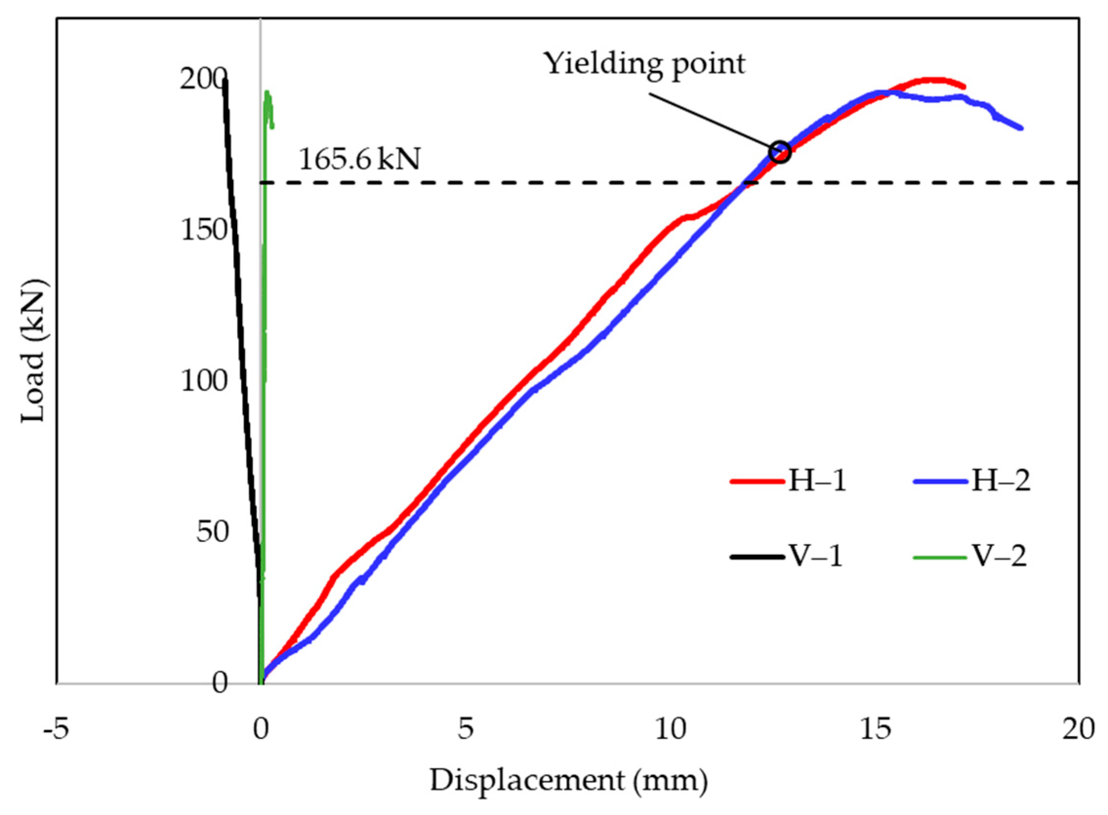
3.1. Load–Displacement of Single Anchor

This experiment was conducted to assess the performance of the individual anchor during the linear-plastic stage. In Figure 8, the single anchor displayed a linear response until the applied load of 176 kN corresponded to the horizontal displacement of 12.70 mm. Then, the behavior gradually shifted toward the yielding stage with a maximum applied load of 197.9 kN. At this point, the average horizontal and vertical displacements of the single anchor measured 15.77 mm and 0.37 mm, respectively. During the anchor tests, the axial deformation of the high-strength anchor bolt was notably lower than the displacement observed for the remaining components constituting the anchor. The main factor influencing anchor displacement under load was the disparity in diameter between the hole and the anchor bolt, coupled with the deformation of the insulation pad, fixed base plate, and DCP steel frame. Notably, the negligible vertical displacement observed was evidence of the feasibility of the anchor structure, especially the connection between the bolts and sleepers in preventing pullout and local rotation. The results from the tests involving single anchors are presented in Table 1.

3.2. Load–Displacement of Steel DCP System

Figure 9 displays the load–displacement curves for the DCP system in the three cases, with the load cell applied at the mid-anchor (Case 1), mid-span (Case 2), and end-anchor (Case 3). Each load case was repeated twice to obtain the average value to ensure accuracy. The full-scale structural tests were successfully conducted, with the recorded data mostly clustering around the average value and exhibiting low standard deviations, as indicated in Table 2. Overall, the DCP system showed a linear response until reaching the target load of 207 kN, which exceeded 125% of the designed load of 165.6 kN. In Figure 9a–c, the observation validated that the structure could uphold its integrity under applied loads with elastic deformations recognized. Notably, the LVDTs’ displacement did not return to the original position after unloading, with the primary cause being localized displacements in the components constituting the anchor. For Case 1, the average displacement values of LVDTs L1, L2, and L3 were 4.35 mm, 5.35 mm, and 5.84 mm, respectively. Even though the LVDT at the mid-anchor indicated the maximum value, these displacements showed only a minor discrepancy. This suggested that the main factor contributing to the DCP displacement was the deformation of the components constituting the anchor, given the negligible deflection of LVDTs observed in the steel DCP, as shown in Figure 9a.
Case 2 showed average displacements of 8.93 mm for LVDT L1, 7.83 mm for LVDT L2, and 6.98 mm for LVDT L3, as depicted in Figure 9b. It is worth mentioning that the maximum displacement at the end-anchor surpasses that achieved at the mid-span (the applied load position) due to the significant difference in stiffness between the steel DCP frame and the steel anchor. In Case 3, LVDTs L3 and L4 exhibited the most substantial displacement with an average of 8.43 mm, while LVDTs L1 and L2 recorded displacements of 1.74 mm and 4.64 mm, respectively, as illustrated in Figure 9c. It was evident that under the same applied load (207 kN), the maximum displacement of 8.93 mm in Case 2 was 1.53 and 1.06 times higher than Cases 1 and 3, respectively. It indirectly validated that Case 2 might be the most adverse loading scenario. The experimental data for all tested cases are summarized in Table 2.
To sum up, the proposed design maintained its structural integrity. It exhibited maximum displacements of 4.58 mm in Case 1, 7.16 mm in Case 2, and 6.07 mm in Case 3 at the designed load of 165.6 kN. Moreover, during the single anchor test, the steel bolts reached the yield stage at the applied load of 176 kN, while the DCP system continued to respond with linear elasticity of the applied load of 207 kN or higher. It showed substantial differences in the cooperative forces between neighboring anchors and the redistribution of internal forces within the DCP systems in cases of different applied loads. Based on the design criteria, the proposed DCP system demonstrated feasibility for its implementation within the Korean railway system. It is worth mentioning that the present analysis only covers the most unfavorable loading scenarios without considering safety-biased group effects among DCPs.

3.3. Initial Stiffness Analysis

The initial stiffness of the structures could affect the displacement and the displacement ductility estimation in displacement-based designs, which mainly depend on factors like shape, size, material properties, and support conditions [41,42]. The slope of the load–displacement curve during the linear elastic stage presents the initial stiffness of the DCP system. It is determined by dividing the applied load by the respective displacement at the load application point [43]. In this study, Case 1 showed the highest initial stiffness among the tested cases, estimated at 35.44 kN/mm. On the other hand, the initial stiffness in Case 2 (26.78 kN/mm) and Case 3 (24.62 kN/mm) was relatively lower, approximately 1.32 to 1.44 times less than that observed in Case 1. These results demonstrated that the initial stiffness of the steel DCP system was significantly affected by the positions of the applied loads. In addition, we could confirm the mobilization of the bearing capacity between neighboring anchors in the proposed structure when the initial stiffness in Cases 1, 2, and 3 exceeded the initial stiffness of the single anchor (13.92 kN/mm) by factors of 2.55, 1.92, and 1.77, respectively. This analysis provided greater insight into the structural responses, serving as a cornerstone for advancing simulation research and addressing the multifaceted challenges associated with mitigating damage from a train derailment.

4. Conclusions

This study investigated the behavior of DCP systems made of steel under different quasi-static loading scenarios. The primary focus was on analyzing the global response of the proposed systems to evaluate their feasibility in mitigating damage during train derailments. The study also concerned the relationship between the applied load and displacement, coupled with the initial stiffness of the DCP systems. The conclusions drawn from the study are as follows:
The anchor structure proved its capability to withstand impact forces by effectively preventing the pullout and local rotation of the steel frame through the single anchor test, achieving a yield strength of 176 kN and a maximum load of 197.9 kN.
The DCP specimens revealed maximum displacements of 7.16 mm at 165.6 kN while maintaining elasticity and structural integrity at 207 kN. The main factor causing DCP displacement was the deformation and localized displacements of the components constituting the anchor, with the maximum displacement in Case 2 measuring 8.93 mm, which exceeded Case 1 by 1.53 times and Case 3 by 1.06 times.
The initial stiffness of the DCP systems, ranging from 1.77 to 2.55, exceeded that of the single anchor. This verified the force-bearing coordination mechanisms among neighboring anchors and the notable differences between loading scenarios.
The proposed system would be viable for minimizing damage during derailments. Nevertheless, further research on impact loads, local bearing capacity, and the reliability of the DCP system is recommended to meet the specified standards in Korea and comparable railway systems.

Author Contributions

Conceptualization, J.J.K.; methodology, H.-J.K., N.-H.L., and J.J.K.; software, H.Q.N. and Y.-S.K.; validation, H.-J.K., N.-H.L., and Y.-S.K.; formal analysis, H.Q.N. and Y.-S.K.; investigation, H.-J.K., N.-H.L., and J.J.K.; data curation, J.J.K. and H.Q.N.; writing—original draft preparation, H.Q.N. and J.J.K.; writing—review and editing, H.Q.N., Y.-S.K., H.-J.K., N.-H.L., and J.J.K.; visualization, H.-J.K. and N.-H.L.; supervision, J.J.K.; project administration, H.-J.K. and N.-H.L.; funding acquisition, N.-H.L. All authors have read and agreed to the published version of the manuscript.

Funding

This work was supported by a Korea Agency for Infrastructure Technology Advancement (KAIA) grant funded by the Ministry of Land, Infrastructure and Transport (Grant RS-2021-KA163289).

Data Availability Statement

Data are contained within the article.

Conflicts of Interest

Author Hoe-Jin Kim was employed by the company UB E&C Co., Ltd. The remaining authors declare that the research was conducted in the absence of any commercial or financial relationships that could be construed as a potential conflict of interest.

References

  1. Kim, H.; Sultana, S.; Weber, J. A geographic assessment of the economic development impact of Korean high-speed rail stations. Transp. Policy 2018, 66, 127–137. [Google Scholar]
  2. Jia, S.; Zhou, C.; Qin, C. No difference in effect of high-speed rail on regional economic growth based on match effect perspective? Transp. Res. Part A Policy Pract. 2017, 106, 144–157. [Google Scholar] [CrossRef]
  3. Verma, A.; Sudhira, H.S.; Rathi, S.; King, R.; Dash, N. Sustainable urbanization using high speed rail (HSR) in Karnataka, India. Res. Transp. Econ. 2013, 38, 67–77. [Google Scholar]
  4. Yang, X.; Lin, S.; Zhang, J.; He, M. Does High-Speed Rail Promote Enterprises Productivity? Evidence from China. J. Adv. Transp. 2019, 2019, 1279489. [Google Scholar]
  5. Yanhui, L.; Al-Bukhaiti, K.; Shichun, Z.; Abas, H.; Nan, X.; Lang, Y.; Yu, Y.X.; Daguang, H. Numerical study on existing RC circular section members under unequal impact collision. Sci. Rep. 2022, 12, 14793. [Google Scholar] [PubMed]
  6. Montenegro, P.A.; Carvalho, H.; Ribeiro, D.; Calçada, R.; Tokunaga, M.; Tanabe, M.; Zhai, W.M. Assessment of train running safety on bridges: A literature review. Eng. Struct. 2021, 241, 112425. [Google Scholar]
  7. Cao, Y.; An, Y.; Su, S.; Xie, G.; Sun, Y. A statistical study of railway safety in China and Japan 1990–2020. Accid. Anal. Prev. 2022, 175, 106764. [Google Scholar]
  8. Evans, A.W. Fatal train accidents on Europe’s railways: An update to 2019. Accid. Anal. Prev. 2021, 158, 106182. [Google Scholar]
  9. Liu, X.; Rapik Saat, M.; Barkan, C.P.L. Freight-train derailment rates for railroad safety and risk analysis. Accid. Anal. Prev. 2017, 98, 1–9. [Google Scholar]
  10. European Union Agency for Railways. Report on Railway Safety and Interoperability in the EU; Publications Office of the European Union: Luxembourg, 2022.
  11. Zhang, Z.; Turla, T.; Liu, X. Analysis of human-factor-caused freight train accidents in the United States. J. Transp. Saf. Secur. 2021, 13, 1157–1186. [Google Scholar]
  12. Dindar, S.; Kaewunruen, S.; An, M. A hierarchical Bayesian-based model for hazard analysis of climate effect on failures of railway turnout components. Reliab. Eng. Syst. Saf. 2022, 218, 108130. [Google Scholar] [CrossRef]
  13. Wu, X.; Chi, M.; Gao, H.; Ke, X.; Zeng, J.; Wu, P.; Zhu, M. Post-derailment dynamic behavior of railway vehicles travelling on a railway bridge during an earthquake. Proc. Inst. Mech. Eng. Part F J. Rail Rapid Transit. 2014, 230, 418–439. [Google Scholar] [CrossRef]
  14. Heleno, R.; Montenegro, P.A.; Carvalho, H.; Ribeiro, D.; Calcada, R.; Baker, C.J. Influence of the railway vehicle properties in the running safety against crosswinds. J. Wind Eng. Ind. Aerodyn. 2021, 217, 104732. [Google Scholar] [CrossRef]
  15. Brabie, D.; Andersson, E. Dynamic simulation of derailments and its consequences. Veh. Syst. Dyn. 2006, 44 (Suppl. S1), 652–662. [Google Scholar] [CrossRef]
  16. Brabie, D. Wheel-Sleeper Impact Model in Rail Vehicles Analysis. J. Syst. Des. Dyn. 2007, 1, 468–480. [Google Scholar] [CrossRef]
  17. Brabie, D.; Andersson, E. Post-derailment dynamic simulation of rail vehicles–methodology and applications. Veh. Syst. Dyn. 2008, 46 (Suppl. S1), 289–300. [Google Scholar] [CrossRef]
  18. Kajitani, Y.; Kato, H.; Asano, K. Development of an L-shaped guide to prevent deviation from rails. JR-EAST Tech. Rev. 2010, 15, 53–56. [Google Scholar]
  19. Sunami, H.; Morimura, T.; Terumichi, Y.; Adachi, M. Model for analysis of bogie frame motion under derailment conditions based on full-scale running tests. Multibody Syst. Dyn. 2012, 27, 321–349. [Google Scholar] [CrossRef]
  20. Guo, L.; Wang, K.; Lin, J.; Zhang, B.; Chen, Z.; Song, X.; Du, G. Study of the post-derailment safety measures on low-speed derailment tests. Veh. Syst. Dyn. 2016, 54, 943–962. [Google Scholar] [CrossRef]
  21. Wu, X.; Chi, M.; Gao, H.; Zhang, D.; Zeng, J.; Wu, P.; Zhu, M. The study of post-derailment measures to limit the extent of a derailment. Proc. Inst. Mech. Eng. Part F J. Rail Rapid Transit. 2014, 230, 64–76. [Google Scholar] [CrossRef]
  22. Wu, X.; Chi, M.; Gao, H. The study of post-derailment dynamic behavior of railway vehicle based on running tests. Eng. Fail. Anal. 2014, 44, 382–399. [Google Scholar] [CrossRef]
  23. Tang, Z.; Hu, Y.; Wang, S.; Ling, L.; Zhang, J.; Wang, K. Train post-derailment behaviours and containment methods: A review. Railw. Eng. Sci. 2023. [Google Scholar] [CrossRef]
  24. Zhang, D.; Peng, Y.; Xu, Y.; Du, C.; Zhang, Y.; Wang, N.; Chong, Y.; Wang, H.; Wu, D.; Liu, J.; et al. A high-speed railway network dataset from train operation records and weather data. Sci. Data 2022, 9, 244. [Google Scholar] [CrossRef] [PubMed]
  25. Büchel, B.; Spanninger, T.; Corman, F. Empirical dynamics of railway delay propagation identified during the large-scale Rastatt disruption. Sci. Rep. 2020, 10, 18584. [Google Scholar] [CrossRef] [PubMed]
  26. Cheng, Y.-s.; Loo, B.P.Y.; Vickerman, R. High-speed rail networks, economic integration and regional specialisation in China and Europe. Travel Behav. Soc. 2015, 2, 1–14. [Google Scholar] [CrossRef]
  27. Guo, B.; Ke, J. The Impacts of High-speed Rail on Sustainable Economic Development: Evidence from the Central Part of China. Sustainability 2020, 12, 2410. [Google Scholar] [CrossRef]
  28. Bae, H.-U.; Yun, K.-M.; Moon, J.; Lim, N.-H. Impact Force Evaluation of the Derailment Containment Wall for High-Speed Train through a Collision Simulation. Adv. Civ. Eng. 2018, 2018, 2626905. [Google Scholar] [CrossRef]
  29. Hamilton, B.A. Report on the Findings of: Current Practice and Effectiveness of Derailment Containment Provisions on High Speed Lines; HSL-Zuid Organisation: Zoetermeer, The Netherlands, 2004. [Google Scholar]
  30. Lai, J.; Xu, J.; Wang, P.; Chen, J.; Fang, J.; Ma, D.; Chen, R. Numerical investigation on the dynamic behaviour of derailed railway vehicles protected by guard rail. Veh. Syst. Dyn. 2021, 59, 1803–1824. [Google Scholar] [CrossRef]
  31. Mao, J.h.; Xiang, J.; Gong, K. Mechanism and Application of a New Guard Rail for Improving the Stability of Small Radius Curve Tracks with Continuous Welded Rails. In Proceedings of the 2013 Fourth International Conference on Digital Manufacturing & Automation, Qindao, China, 29–30 June 2013; pp. 773–779. [Google Scholar]
  32. Nishimura, K.; Terumichi, Y.; Morimura, T.; Adachi, M.; Morishita, Y.; Miwa, M. Using Full Scale Experiments to Verify a Simulation Used to Analyze the Safety of Rail Vehicles During Large Earthquakes. J. Comput. Nonlinear Dyn. 2015, 10, 031013. [Google Scholar] [CrossRef]
  33. Authority, K.R.N. Railway Design Guideline and Handbook—Subsidiary and Safety Facilities for Main Lined; KR C-02060; Korea Rail Network Authority: Daejeon, Republic of Korea, 2017. [Google Scholar]
  34. Lim, N.-H.; Kim, K.-J.; Bae, H.-U.; Kim, S. DEM Analysis of Track Ballast for Track Ballast–Wheel Interaction Simulation. Appl. Sci. 2020, 10, 2717. [Google Scholar] [CrossRef]
  35. Song, I.-H.; Koo, J.-S.; Shim, J.-S.; Bae, H.-U.; Lim, N.-H. Theoretical Prediction of Impact Force Acting on Derailment Containment Provisions (DCPs). Appl. Sci. 2023, 13, 3899. [Google Scholar] [CrossRef]
  36. Bae, H.-U.; Moon, J.; Lim, S.-J.; Park, J.-C.; Lim, N.-H. Full-Scale Train Derailment Testing and Analysis of Post-Derailment Behavior of Casting Bogie. Appl. Sci. 2020, 10, 59. [Google Scholar] [CrossRef]
  37. Bae, H.-U.; Kim, K.-J.; Park, S.-Y.; Han, J.-J.; Park, J.-C.; Lim, N.-H. Functionality Analysis of Derailment Containment Provisions through Full-Scale Testing-I: Collision Load and Change in the Center of Gravity. Appl. Sci. 2022, 12, 11297. [Google Scholar] [CrossRef]
  38. Pham, T.M.; Hao, H. Influence of global stiffness and equivalent model on prediction of impact response of RC beams. Int. J. Impact Eng. 2018, 113, 88–97. [Google Scholar] [CrossRef]
  39. Fujikake, K.; Li, B.; Soeun, S. Impact Response of Reinforced Concrete Beam and Its Analytical Evaluation. J. Struct. Eng. 2009, 135, 938–950. [Google Scholar] [CrossRef]
  40. Chungnam-National-University; Korea-Railroad-Research-Institute; CS-Global; UBI-E&C; Korea-Railroad-Authority-&-Road-Kinematics. Facility Development and Performance Standard Research for Rail Vehicle Deviation Protection; Chungnam National University: Daejeon, Republic of Korea, 2020. [Google Scholar]
  41. Tena-Colunga, A. Aspects to Consider in the Assessment of Effective Stiffness for Reinforced Concrete Beams. J. Arch. Eng. 2021, 27, 04020048. [Google Scholar] [CrossRef]
  42. Ding, F.; Ding, H.; He, C.; Wang, L.; Lyu, F. Method for flexural stiffness of steel-concrete composite beams based on stiffness combination coefficients. Comput. Concr. 2022, 29, 127–144. [Google Scholar]
  43. Duy, N.P.; Hiep, D.V.; Anh, V.N. Performance of concrete beams reinforced with various ratios of hybrid GFRP/steel bars. Civ. Eng. J. 2020, 6, 1652–1669. [Google Scholar]
Figure 1. Concepts of DCP in railways.
Buildings 14 00171 g001
Figure 2. General view of steel frame DCP system Type I.
Buildings 14 00171 g002
Figure 3. Details about components of the steel DCP system (unit: mm).
Buildings 14 00171 g003
Figure 4. Installation diagram of a steel DCP system.
Buildings 14 00171 g004
Figure 5. Single anchor test setup.
Buildings 14 00171 g005
Figure 6. General view of steel DCP test setup.
Buildings 14 00171 g006
Figure 7. Test setup of steel DCPs.
Buildings 14 00171 g007aBuildings 14 00171 g007b
Figure 8. Load–displacement relationship of single anchor.
Buildings 14 00171 g008
Figure 9. Load–displacement relationship of DCP with different load locations.
Buildings 14 00171 g009
Table 1. Experimental data of the single anchor.
Specimen ID.Pu (kN)Py (kN)ΔuH (mm)ΔuV (mm)ΔyH (mm)Ki (kN/mm)
S1199.9176.016.34−0.8811.9513.86
S2195.8176.015.200.1411.8613.97
Average197.9 (2.05)176.0 (0)15.77 (0.57)−0.37 (0.51)11.90 (0.04)13.92 (0.05)
Notes: Py and ΔyH represent the yielding load and the associated displacement; Pu, ΔuH, and ΔuV denote the highest applied load and the respective vertical and horizontal displacements; Ki refers to the initial stiffness; the values in parentheses are the standard deviations.
Table 2. Experimental data of the steel DCP system.
NotationCase 1—Load at Mid-AnchorCase 2—Load at Mid-SpanCase 3—Load at End-Anchor
L1L2L3L1L2L3L1L2Aver. L3&L4
Designed load
(165.6 kN)
3.324.204.587.166.325.411.283.345.95
(0.19)(0.24)(0.29)(0.36)(0.52)(0.35)(0.06)(0.00)(0.17)
Target load
(207 kN)
4.355.355.848.937.836.981.744.644.35
(0.13)(0.10)(0.03)(0.35)(0.88)(0.49)(0.04)(0.32)(0.46)
Initial stiffness (kN/mm)35.44 (0.20)26.78 (3.00)24.62 (1.33)
Notes: the values in parentheses are standard deviations.
Disclaimer/Publisher’s Note: The statements, opinions and data contained in all publications are solely those of the individual author(s) and contributor(s) and not of MDPI and/or the editor(s). MDPI and/or the editor(s) disclaim responsibility for any injury to people or property resulting from any ideas, methods, instructions or products referred to in the content.

