Article

Influence of Stress Disturbance on the Deformation of Nearby Cemented Roadways following the Excavation of Chambers

1
School of Energy and Mining Engineering, Shandong University of Science and Technology, Qingdao 266590, China
2
School of Civil Engineering and Architecture, Liaocheng University, Liaocheng 252000, China
3
School of Engineering, China University of Geosciences, Wuhan 430074, China
*
Authors to whom correspondence should be addressed.
Buildings 2024, 14(1), 169; https://doi.org/10.3390/buildings14010169
Submission received: 21 November 2023 / Revised: 22 December 2023 / Accepted: 25 December 2023 / Published: 9 January 2024
(This article belongs to the Special Issue Study of Material Technology in Structural Engineering)

Abstract

:
Based on the engineering background of weakly cemented roadways and adjacent chambers in Western China, a numerical simulation method was used to examine the changes in stress distribution and increment in the surrounding rock of weakly cemented roadways adjacent to chambers. The results show that the surrounding rock stress of the weakly cemented roadway adjacent to the chambers increases by approximately 30%. The vertical stress of the surrounding rock mainly expands along the vertical direction, and the expansion range is 7–12 times that of the chamber height. The horizontal stress of the surrounding rock mainly expands along the horizontal direction, and the expansion range is 3–6 times that of the chamber width. Based on the support idea of “allowable deformation” + “relief pressure” + “maintaining roadway shape”, the support technology of weakly cemented roadways adjacent to chambers is established with “full section U-shaped steel shed + filling flexible materials between the steel shed and surrounding rock + patching the roof bolt + laying concrete on floor”. An engineering test based on the above support technology was carried out, and it was found that the deformation of the weakly cemented roadway adjacent to the chambers was 0 in 20 days.

1. Introduction

The coal resources with good storage conditions in Central and Eastern China have been greatly reduced, leading to the gradual development of mining in the western region. Consequently, the effective exploitation of coal resources in the western region has become a significant concern influencing energy security [1,2,3,4]. Given the unique diagenetic climate and sedimentary procedures in this part of China, a particular type of soft rock, identified as weakly cemented soft rock, is prevalent in the coal measures. Soft rock that is weakly cemented possesses traits such as poor strength and inadequate cementation, making it prone to becoming muddy upon water exposure. This can potentially lead to bolts losing their anchoring ability. Roadways built with weakly cemented material are typically vulnerable to significant issues like rapid decrease in anchoring force, substantial deformation of the neighboring rock, and a brief self-stabilization period. Although the traditional active support methods such as anchor bolt, anchor cable, and combined support with an anchor cable net can effectively control the deformation of the surrounding rock of coal roadways, such methods cannot limit the deformation of the surrounding rock of soft rock roadways and cannot meet the requirements of the support of soft rock roadways under the current coal mining conditions, and the stability of the roadway is difficult to be guaranteed [5,6,7,8,9].
In recent years, many scholars have performed considerable research on weakly cemented rock roadways and control theory and technology of surrounding rock adjacent to chambers. Some scholars have studied the characteristics of weakly cemented roadways from the perspective of laboratory tests and theoretical analysis. Liu et al. [10] combined laboratory tests and theoretical analysis methods; the relation between the permeability and micropore structures was studied, and the permeability evolution mechanism of the weakly cemented sandstones was eventually clarified. By exploring the composition of weakly cemented siltstone. Yu et al. [11] analyzed the unstable factors affecting the weak cemented siltstone roadway and studied the support scheme of this kind of roadway reinforced by grouting. Ru et al. [12] investigated the creep characteristics of weakly cemented soft rock under different initial confining pressures and the influence parameters on the creep characteristics of weakly cemented soft rock. Other scholars used numerical simulation to explore the stress distribution characteristics of weakly cemented roadways and put forward support schemes. Meng et al. [13] used a variety of research methods to analyze the stress distribution characteristics of weakly cemented roadways and proposed a comprehensive reinforcement technology combining high-prestressed strong anchor cables and high-pressure grouting. Through the usage of numerical simulation methods, the distribution characteristics of the deviatoric stress and plastic zone of the encircling rock in a deep mine’s goaf were examined by Huang et al. [14]. Zhang et al. [15] suggested that to effectively regulate weakly cemented roadways and enhance the stress state and mechanical properties of the surrounding rock, careful consideration should be given to the roadway’s support structure, support resistance should be increased, and the roadway section should be optimized. Yang et al. [16] proposed a “strong column and solid bottom” reinforcement design plan for the surrounding rock of a roadway and adjacent chambers within 20 m. Zhou et al. [17] discussed and gave the failure mechanism of weakly cemented roadways and corresponding supporting principles. After testing various support schemes, it was concluded that the passive support of “single prop + top beam” plays an important role in controlling roof subsidence.
The aforementioned research studies serve as valuable resources for managing the rocky surroundings of weakly cemented soft roadways and neighboring chambers [18,19,20,21,22,23]. However, there is little research on the support of weakly consolidated roadways disturbed by the excavation of the surrounding chamber. In field engineering, support parameters are usually designed according to experience, which cannot effectively ensure the stability of the roadway.
Therefore, further analysis is still needed to understand the stress distribution in the rocks surrounding such roadways near chambers and to explore the intrinsic connection between the stress distribution in rocks and the structural stability support of the roadway [24,25,26,27]. This study utilizes the numerical simulation technique to investigate the stress distribution patterns and increase in stress over time in the weakly cemented passageways of a coal mine in Western China. Its aim is to ascertain the stress distribution and stability support mechanism of the adjoining weakly cemented soft roadways near cavities.

2. Research Background

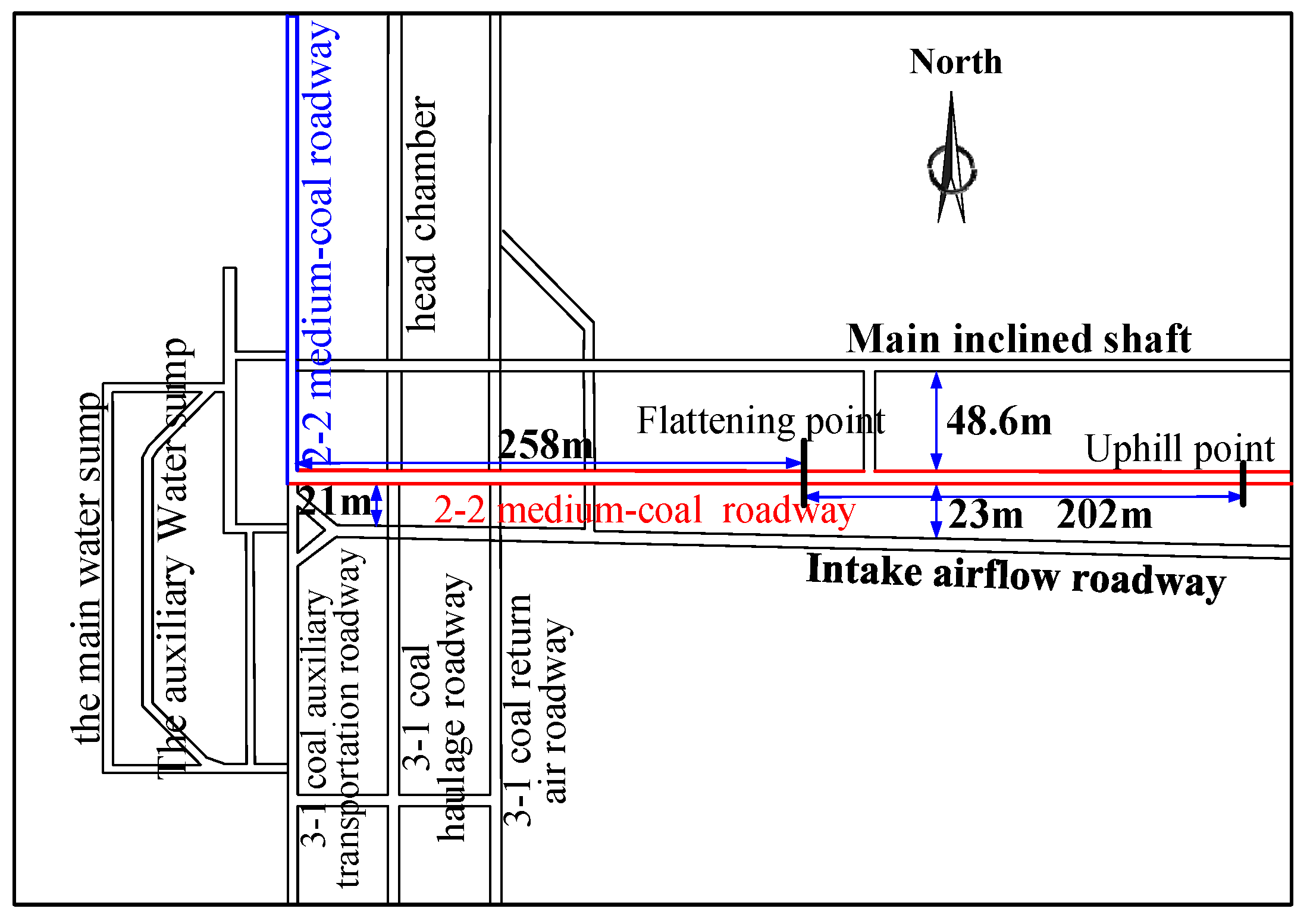
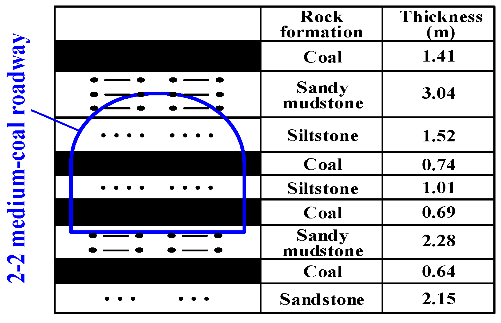
2.1. General Situation of Roadway Geology and Support

This research focuses on conducting research on the 2-2 medium-coal roadway in a coal mine located in Western China. Figure 1 displays the position of the 2-2 medium-coal roadway. The 2-2 medium-coal roadway is excavated horizontally from the 3-1# coal to the 2-2# coal from east to west, with a total length of 572 m, buried depth of 400 m, and the length to the uphill point is 460 m. The 2-2 medium-coal roadway is 27–45 m above the chambers of 3-1# coal. The 2-2 medium-coal roadway is about 48.6 m away from the main inclined shaft on the north side, and its width increases from 21 m to 25 m from west to east to the south side of the intake airflow roadway. The west opening of the 2-2 medium-coal roadway is connected with the transportation roadway.
The 2-2 medium-coal roadway is designed with a cross-section that features a straight wall and a semi-circular arch. It measures 5.4 m wide and 4.1 m high. Figure 2 illustrates that the roof comprises mainly sandy mudstone and siltstone, with the floor also predominantly made up of sandy mudstone. Figure 3 displays the support section of the 2-2 medium-coal roadway with detailed support parameters enumerated in Table 1.

2.2. Reasons for Deformation of Weakly Cemented Soft Roadways

Once the digging process of the 2-2 medium-coal pathway was finalized, the nearby rock situated 150 m away from the transporting roadway showed significant deformity, causing damage to the support structure. Over the span of two weeks, the total dimensional change of the 2-2 medium-coal pathway’s roof and floor surpassed 1500 mm. The distortion in the adjacent rock exhibited both asymmetrical and varying traits. The overall deformation is large, and the anchors fall off in some areas. Figure 4 shows the roadway deformation. The deformation of the roadway side gradually increases within 15 days after roadway excavation, the roof subsidence is small in amplitude, and the bottom floor has a slime phenomenon.

2.2.1. Stress Concentration from Adjacent Chambers

Utilizing the engineering analogy method, this synopsis determines that given identical coal and rock conditions, as well as the same original rock stress and support methods, the roadway incurs damage due to variations in the chamber distribution range. Combined with Figure 1, it can be seen that the instability observed in the 2-2 transportation-inclined roadway is primarily influenced by the stress concentration from neighboring chambers. Table 2 provides a statistical breakdown of the results garnered from the comparison analysis of the engineering project.
An engineering analogy reveals that the degree of damage in weakly cemented soft roadways is directly proportional to the distribution distance from the neighboring chambers, providing the rock conditions, initial rock stress, and support method remain consistent. Therefore, it is speculated that the main cause of damage in the 2-2 medium-coal roadway is affected by the stress concentration of adjacent chambers, and the specific impact characteristics will be analyzed in detail later. Table 2 shows the analysis results of the engineering analogy. According to the actual situation on site, parts of roadway deformation exceeding 100 mm are divided into damaged sections, and the roadway deformation parts below this value are divided into safety sections.

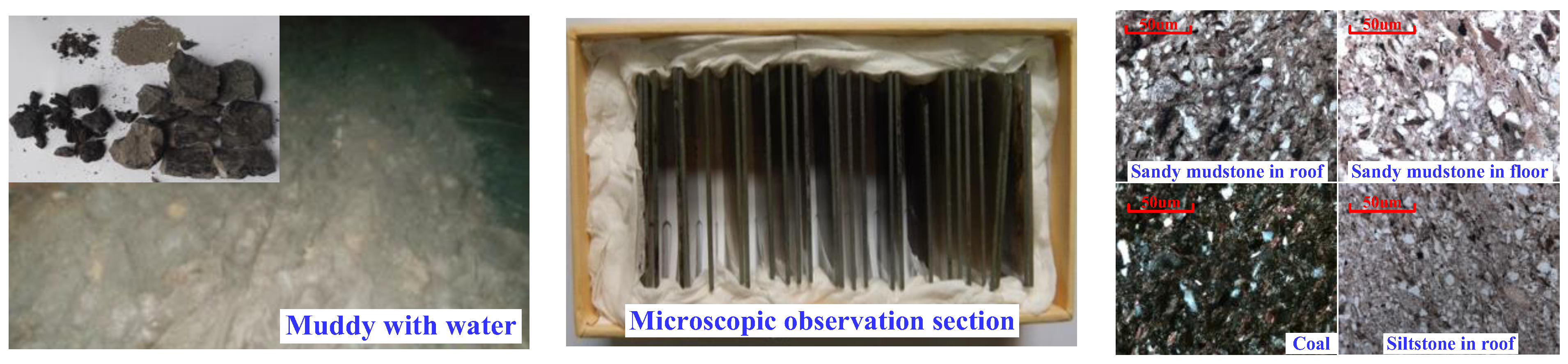
2.2.2. Physical and Mechanical Properties of Surrounding Rock

For the weakly cemented soft rock surrounding the 2-2 medium-coal roadway, a combination of sampling and various property tests was performed which tested attributes such as density, elastic modulus, compressive strength, tensile strength, cohesion, and internal friction angle. The results of these tests are depicted in Figure 5 and summarized in Table 3. The bearing capacity of surrounding rock is negatively impacted by the reduced compressive strength and cohesion found in weakly cemented rock compared to ordinary soft rock.
The surrounding rock of the 2-2 medium-coal roadway was microscopically analyzed, and the physical components of the roadway roof and floor were obtained, as listed in Table 4. The mineral composition is mainly clay minerals such as chlorite, indicating that there are many voids in the rock mass and good connectivity, resulting in a weak overall structure and easy swelling and disintegration in contact with water.

3. Stress Distribution Characteristics of Surrounding Rock

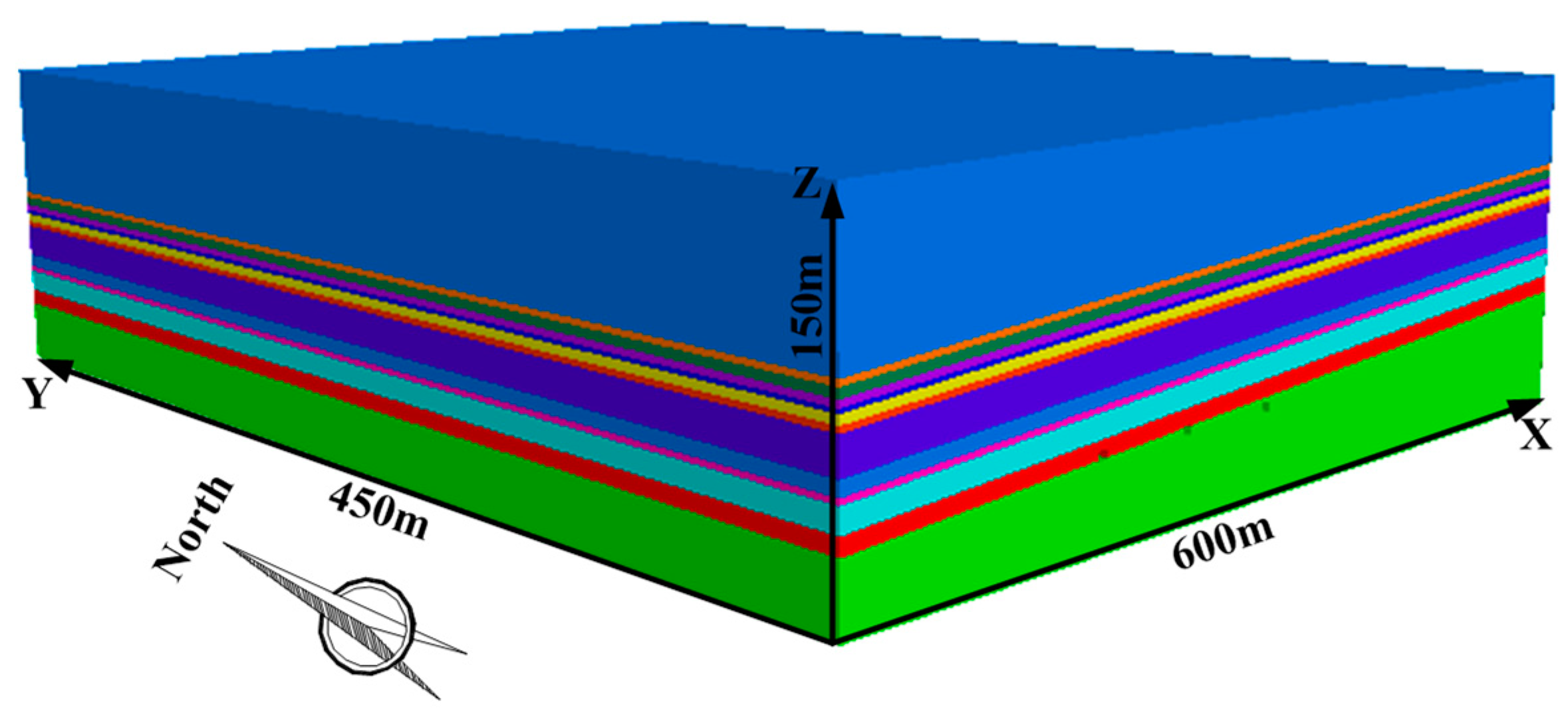
3.1. Numerical Model Construction

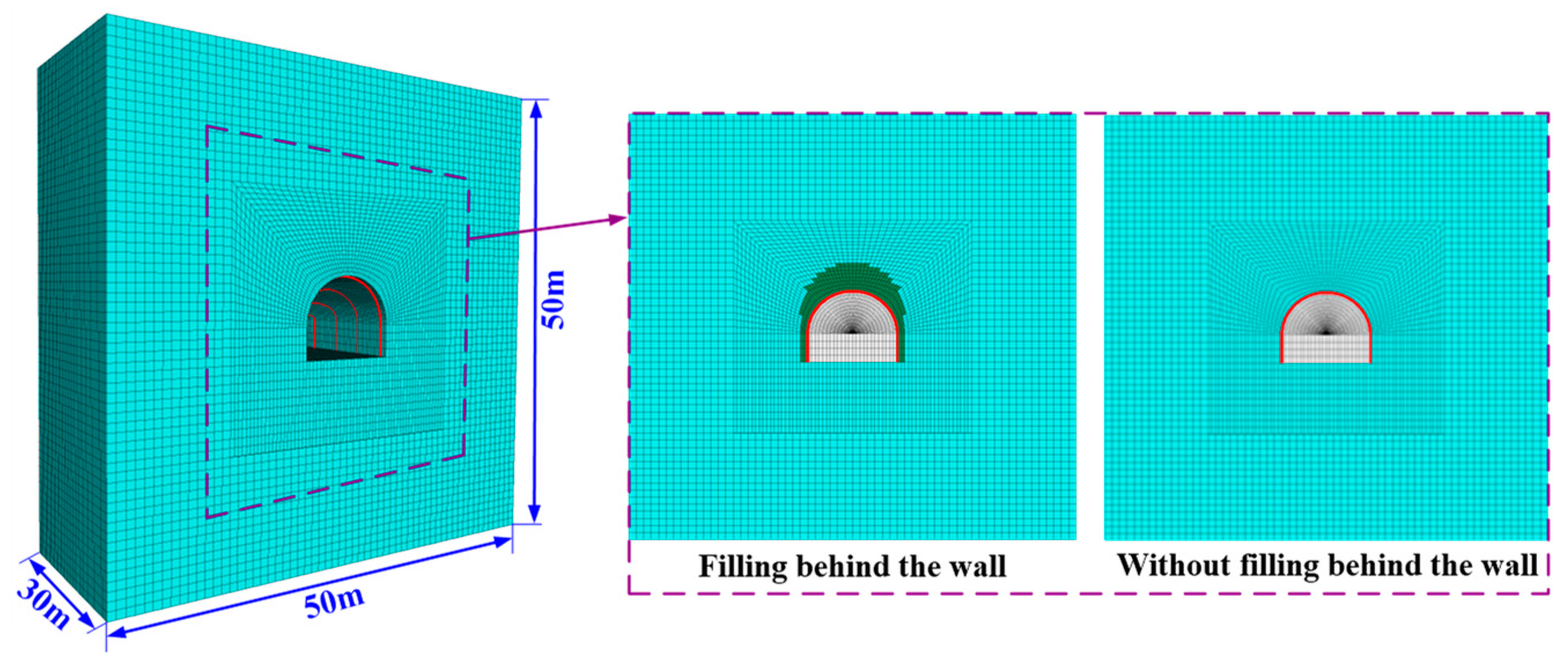
3.1.1. Numerical Model Size

FLAC3D 5.0 software was used for numerical simulation, and the actual model was simplified to establish a three-dimensional model. The boundary effect’s impact was lessened by enlarging the boundary of the engineering model suitably. The model extends 600 m along the X-axis, 450 m along the Y-axis, and 150 m along the Z-axis. The numerical model is shown in Figure 6.

3.1.2. Unit Parameters of Numerical Model

The numerical model’s rock stratum’s dip angle was set to 5°, accounting for the coal mine’s engineering geological conditions. It was homogeneous with a uniform thickness. Fine sandstone from the 2# coal formed the upper boundary of the numerical model, while the lower boundary comprised fine sandstone from the coal 3#. The numerical model’s constitutive relation is defined by the elastic–plastic M-C model. The numerical model necessitates the calculation of certain physical and mechanical parameters of the rock stratum, which are presented in Table 5.

3.1.3. Calculation Scheme of Numerical Model

The numerical model’s front, back, left, right, and top parameters were determined with stress control according to the in-situ stress test outcomes, while displacement control was applied to the bottom parameter. This is demonstrated in Figure 7. A horizontal pressure of 25 MPa was applied to the model’s left and right limits, 7 MPa horizontal stress to the front and rear limits, and 10 MPa vertical stress to the top parameter, while the bottom limit restricted the model’s displacement. The yellow dotted line in Figure 5 indicates the excavation scope of the chambers. The protocol for the simulation is as follows: ① establishing the initial in situ stress balance state, ② excavation of unsupported chambers of 3-1# coal, ③ excavation of supported 3-1# coal, and ④ the excavation step is 20 m.

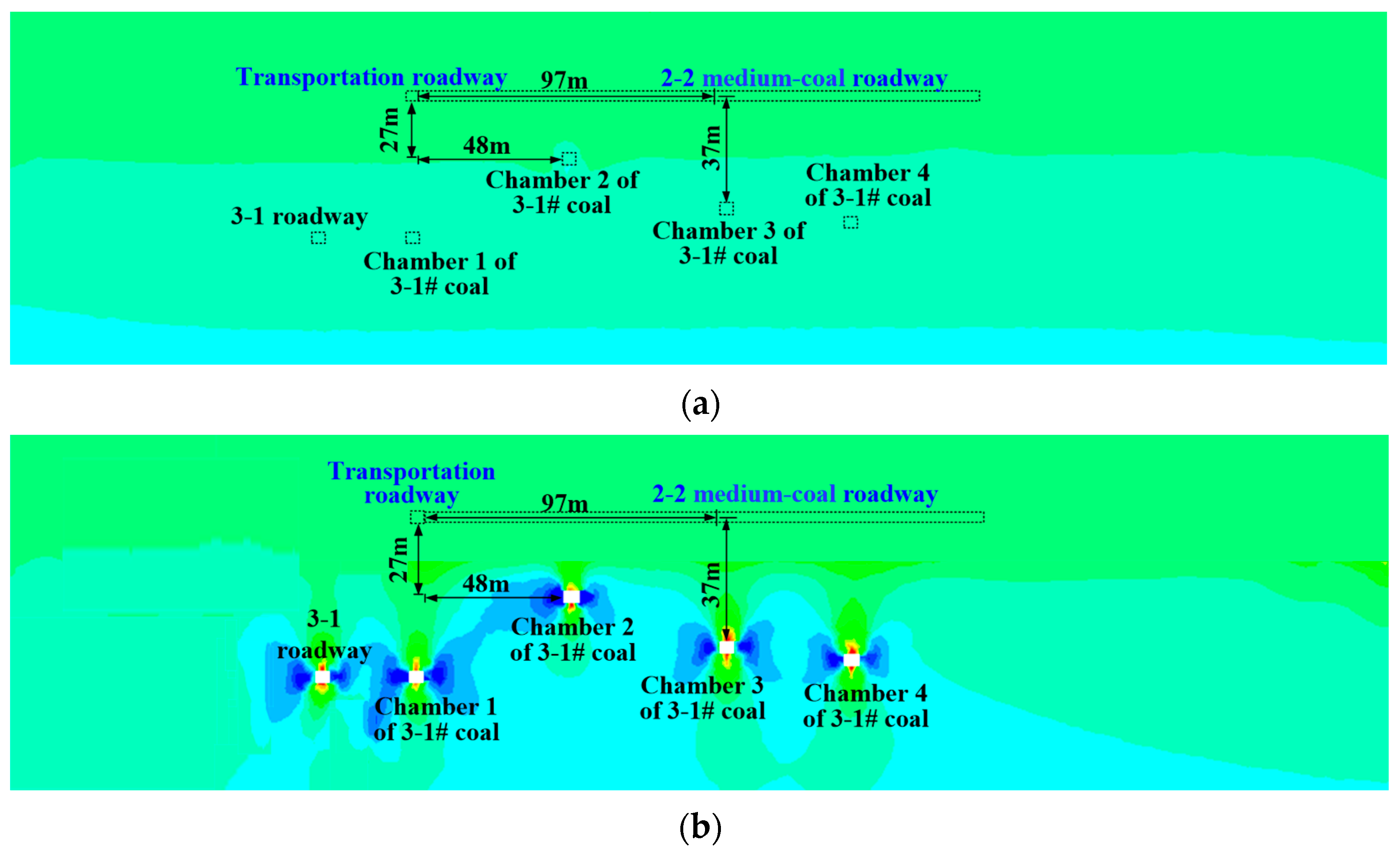
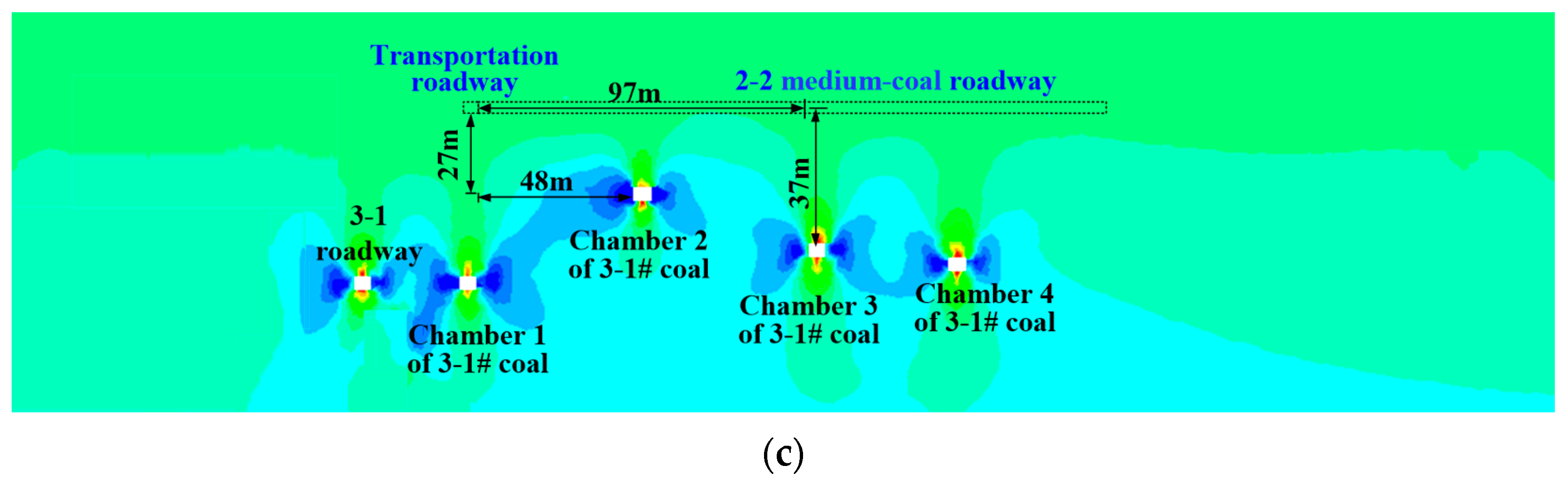
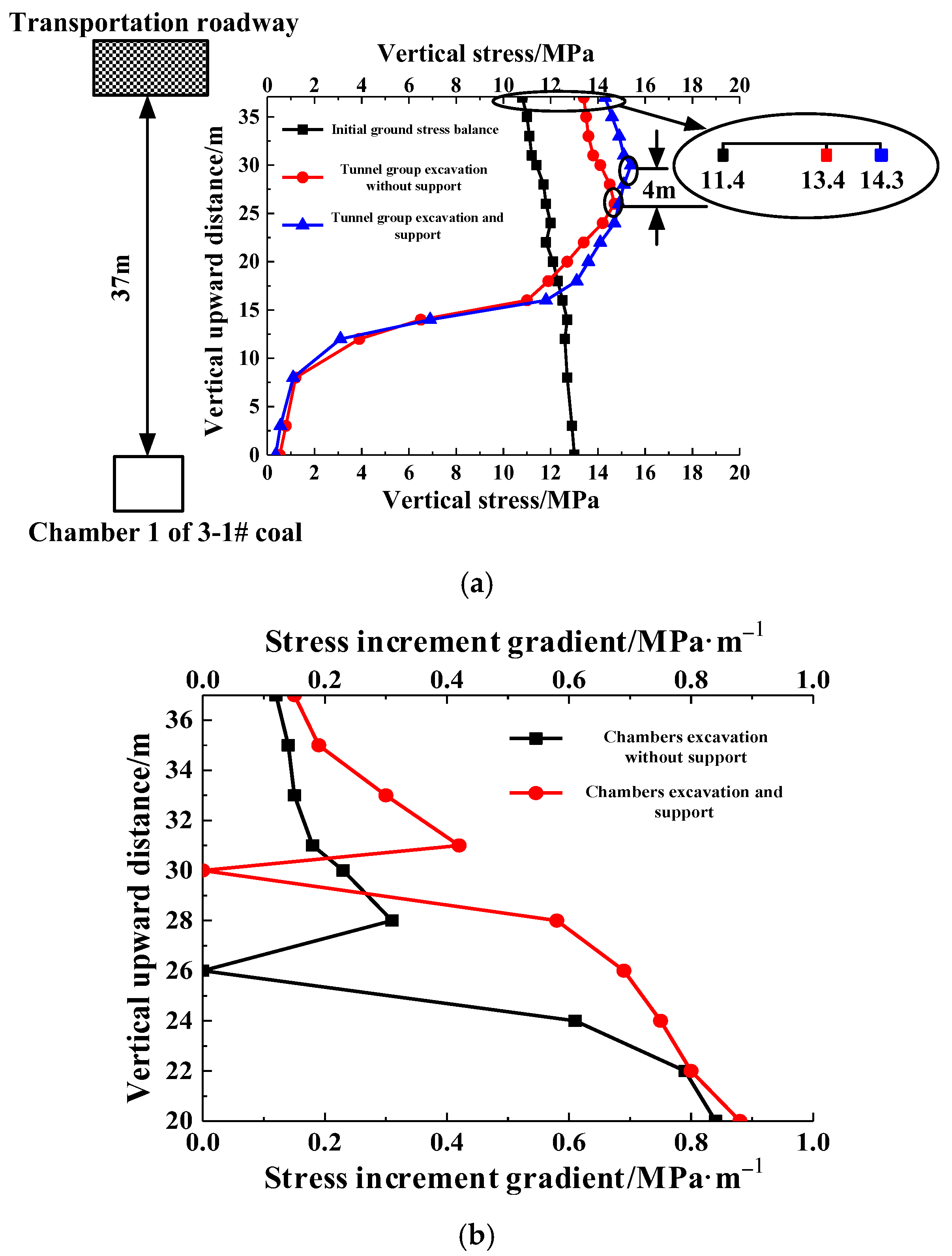
3.2. Stress Distribution Characteristics of Surrounding Rock

The numerical calculations indicate that Figure 8 depicts the vertical stress distribution of the 2-2 medium-coal roadway, while Figure 9 presents the spatial distribution curve of the vertical stress.
As shown in Figure 8, when the initial in situ stress is balanced, the 2-2 medium-coal roadway’s vertical stress on the rock layer is 11.4 MPa. This is less than the 13.6 MPa recorded in chamber 1 of the 3-1# coal and the 12.4 MPa found in chamber 2 of the 3-1# coal. Once the 3-1# coal chambers are excavated, the nearby rock strata of both chamber 1 and chamber 2 are impacted by the mining operation, resulting in the vertical stress dropping to 0.3 MPa and 0.4 MPa, respectively. In the 2-2 medium-coal roadway above chamber 1 and chamber 2 of 3-1# coal, the vertical pressures exerted by the neighboring rock are, respectively, 13.9 MPa and 13.4 MPa.
The above description illustrates that the excavation of the chambers in 3-1# coal releases a certain vertical stress to the position of the 2-2 medium-coal roadway. Once the 3-1# coal chambers are fortified, the mid-point of the release zone for the stress of the surrounding rock extends upwards by 4 m for both chamber 1 and chamber 2. The vertical pressure of the adjacent rock in the 2-2 intermediate-coal roadway subsequently intensifies to 14.8 MPa and 14.3 MPa, which is a respective increase of 3.4 MPa and 2.9 MPa compared to the original in situ stress equilibrium.
As the vertical distance increases, the gradient of the vertical stress increment for the rock layer above the 3-1# coal chambers initially declines, then increases, and finally decreases again. The stress increment gradient reaches its peak of 0.82–0.86 MPa∙m−1 when the distribution stress of the rock layer exceeds the original in situ stress. The stress increment gradient subsequently declines as the vertical distance grows. The increase in stress gradient drops to 0 in the stress release zone of the adjacent rock. The stress increment gradient changes from 0.42–0.44 MPa∙m−1 to 0.12–0.16 MPa∙m−1 as the vertical distance continues to increase. The stress from the neighboring rock, as described above, moves upwards to the location of the 2-2 medium coal passage after supporting the 3-1# coal units. The digging and additional support of these 3-1# coal units intensify the stress concentration in the 2-2 medium coal passage.
When the chambers of 3-1# coal are unearthed without any support, the vertical stress on the medium-coal roadway 2-2 resting above chamber 2 of 3-1# coal escalates from 11.4 MPa to 13.9 MPa. The pressure on the 2-2 medium-coal roadway over chamber 1 of 3-1# coal also elevates from 12.4 MPa to 14.4 MPa. When the 3-1# coal chambers receive support during the excavation process, the vertical stress on the 2-2 medium-coal roadway above chamber 2 of 3-1# coal further increases from 13.9 MPa to 14.8 MPa. The vertical stress of the 2-2 medium-coal roadway above chamber 1 of 3-1# coal increased from 14.4 MPa to 15.3 MPa. Following the excavation of the chambers, there is a notable increase in the degree of stress concentration and deformation of the rock surrounding the adjacent weakly cemented soft roadway.

4. Soft Rock Roadway Support Design

4.1. Analysis of Support Ideas

Following the excavation of the chambers, the increased stress on the surrounding rock combines with the existing rock stress. This total stress surpasses the critical stress point which causes the deterioration of the surrounding rock. Consequently, the weakly cemented soft roadway adjacent to the chambers crumbles. For the safe and normal operation of the roadway, and to manage the deformation of the neighboring rock within acceptable parameters, the support structure must possess significant support strength, be adaptable in form, and be capable of sustaining extended periods of deformation and high resistance. Given the U-shaped steel shed’s ability to uphold the structure of the roadway section and offer comprehensive support, it is crucial to utilize this U-shaped steel shed as the primary means of support.
The contact between the U-shaped steel shed and nearby rock is challenging due to the significant distance between them and the irregular surface of the rock. As a result, U-shaped steel sheds are easily damaged to varying degrees under concentrated loads, reducing the bearing capacity of U-shaped steel sheds and other supporting components. Therefore, on the basis of the full section of the U-shaped steel shed supporting the roadway, it is necessary to fill flexible materials between the U-shaped steel shed and surrounding rock and combine the U-shaped steel shed and flexible materials to form a supporting structure. The above supporting structure can not only realize the uniform and stable release of surrounding rock stress, but also maintain the shape of the roadway section for a long time.
In order to minimize harm to the U-shaped steel shed from nearby rock extrusion, and to maintain surrounding rock deformation under control, it is crucial to reinforce the support on significant components and raise the maximum load-bearing stress of the support structure. When supporting a weakly cemented soft roadway, full consideration should be given to “allowing deformation”, “releasing stress”, and “limiting shape”. “Allowing deformation” refers to the capacity of the supporting structure to permit a certain level of space for the deformation of nearby rocks. The term “releasing pressure” implies that the surrounding rock can relieve a specific amount of stress. The term “limiting state” refers to the restriction of the deformation of the adjacent rock to a manageable extent to maintain the shape of the roadway section, as detailed in Table 6.

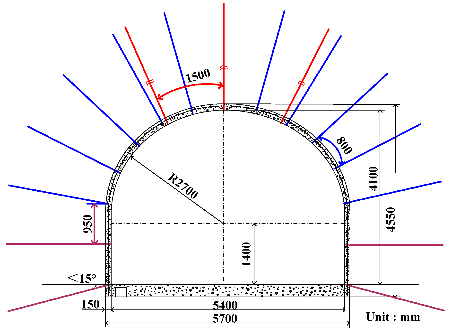
4.2. Determination of Support Parameter

Before executing the parameter design of the support scheme centered around “allowing deformation”, “releasing stress”, and “limiting shape”, it is vital to first calculate the size of the 2-2 medium-coal roadway support section and the thickness of the flexible materials to be filled.
Figure 10 shows the need to maintain a section size of 4.6 m (width) by 4.1 m (height) for the 2-2 medium-coal roadway in order to meet the functional requirements for transporting employees and materials, and due to construction cost considerations. The roadway features a 2.3 m radius semi-circular arch with a straight wall height of 1.8 m. Once debris from the roof and floor are cleared, the rooftop, both sides, and the floor each provide space measuring 1.6 m, 0.5 m, and 0.3 m, respectively. The roof is filled with pebbles to a thickness of 1.5 m, accompanied by a 0.1 m thick U-shaped steel layer, with the sides filled to a thickness between 0.3 and 0.5 m. There is also a 0.3 m thick layer of concrete on the floor.
Following the determination of the roadway section size, a numerical calculation model was established to examine the control effect of a full-section U-shaped steel shed support, along with cobble fillings between the steel shed and the surrounding rock, on the deformation of the surrounding rock. As depicted in Figure 11, the model dimensions are 50 m in height, 50 m in width, and 30 m in thickness. The constitutive relation chosen for this study is the Mohr–Coulomb model. The model’s top was subjected to a vertical stress of 10 MPa, while its left and right edges experienced a horizontal stress of 25 MPa. The model’s front, rear, and bottom borders are displacement boundaries. U-shaped steel adopted a beam unit.
Figure 12 lists the results before and after pebble filling. The effects of failure on the surrounding rock remain unchanged pre and post cobble filling. The bottom showcases tensile failure while the sides display shear failure, and the top reflects a combination of tensile and shear failure. The disparity lies in the expansion of the plastic zone in the surrounding rock post cobble filling. The extent of the plastic zone enlarges from covering 20% of the roadway’s width to covering 40% after cobble filling. The growth of the plastic zone at the shoulder corner of the roadway is highly noticeable, reaching a maximum value of 60% of the roadway’s width. The calculation results show that obvious deformation occurs after cobble filling, which is beneficial for improving the interaction between the surrounding rock and the U-shaped steel shed.
Figure 13 shows the distribution characteristics of stress and plastic zone of sur-rounding rock under different shed spacing conditions. Cobble filling triggers a noticeable alteration in the horizontal and vertical stress distribution characteristics of the surrounding rock. Prior to cobble filling, the maximum vertical stress of the surrounding rock measures 1.24 MPa, while the maximum horizontal stress measures 0.12 MPa. The extension length of an axial force greater than 170 kN on a U-shaped steel shed stands at 2.03 m. After cobble filling, the highest vertical stress exerted on the surrounding rock is 3.48 MPa, and the most significant horizontal stress is 1.12 MPa. The U-shaped steel shed axial force’s distribution length exceeds 170 kN, measuring 5.35 m. Before the filling of cobbles, the edge of the rock’s stress distribution range was 0.05 m from the U-shaped steel shed. However, after the cobble filling, the stress distribution range edge was 0.3 m from the U-shaped steel shed. The results from the previously mentioned calculations demonstrate that filling the gap with pebbles between the U-shaped steel shed and the neighboring rock can significantly hinder direct interaction between the two. Moreover, this can also decrease the stress that the surrounding rock exerts on the U-shaped steel shed.
The distribution scope of the plastic zone in the 2-2 medium-coal roadway is diminished following the backing of the U-shaped steel shed. When the shed spacing is 0.8 m, the plastic zone is concentrated at the edge of the U-shaped steel shed. The plastic zone focuses on the roof when the shed spacing measures 1 m, with a plastic zone range of 0.2 m. Conversely, an increase in the shed spacing to 1.2 m leads to a notable expansion of the plastic zone, with its range growing to 0.5 m, far larger than that of shed spacing of 0.8 m and 1 m. Moreover, the effect of this decrease on the plastic zone’s area is roughly equivalent to shed spacings of 0.8 m and 1 m.
Figure 14 shows the amount of roadway deformation after adopting the new support method. As can be seen from the figure, the deformation of the roof, floor, and left and right sides of the roadway is always 0 within 20 days; that is, after the new support method is adopted, the deformation of the weakly cemented roadway adjacent to chambers had no deformation.

5. Discussion

The summary of the plastic zone and horizontal displacement distribution traits of the surrounding rock related to rectangular, trapezoidal, and straight wall roadway sections with a semi-circle and tangent arch is outlined in Figure 15. The plastic zone of the surrounding rock becomes significantly broad when the roadway’s section shape is a trapezoid and a straight wall with a tangential arch, measuring 2.41 m and 2.35 m in width, respectively. When the shape of the roadway section is a straight wall combined with a semicircular arch and a rectangle, the burdened rock area is minimal, with widths measuring 1.75 m and 1.96 m, respectively. However, when the road’s section shape is a straight wall with a semicircular arch only, the extent of the burdened area is at its slightest. The horizontal displacement of the surrounding rock is minimal (108.66 mm and 124.93 mm, respectively) when the roadway has a section shape of a straight wall combined with a semicircle arch and a rectangle. The smallest horizontal displacement occurs when the roadway’s section shape is a straight wall accompanied by a semicircular arch.
For instance, when considering a trapezoid section shape and a straight-wall roadway with a tangential arch, the horizontal displacement for the two sides increases to 2.38 and 1.94 times that of the rectangular roadway, implying a rise of 138% and 94%, respectively. When the road design features a rectangular form with a semi-circular arch, the horizontal shift on both sides is 0.85 times the displacement of the straightforward rectangular road, signifying a 15% reduction.
The analysis indicates that when the section shape is rectangular, it exhibits minimal plastic zone range and horizontal displacement of its sides. This is particularly true for straight walls with a semicircular arch, which yield the smallest range and displacement of any section shape.

6. Conclusions

(1) Once the group of chambers has been excavated, the stress from the surrounding rocks will be dispersed to the neighboring weakly bonded rock formations. The expansion of the vertical stress predominantly occurs in the upward direction, with the expansion distance amplifying as more roadways are excavated. This can impact the rock formation’s position to a distance equivalent to 7–12 times the height of the chamber.
(2) Following the unearthing of the chamber group, horizontal pressure mainly widens in a lateral direction. The magnitude of this expansion grows in proportion to the quantity of roadways excavated. This can influence the location of the rock layer up to a scope that is 3–6 times the width of the chamber itself. The concentration of stress in the weakly cemented rock layer primarily originates from the vertical discharge of stress caused by the chamber group.
(3) The roadway support technology with U-shaped steel as the core, cobblestone wall filling, and key parts-reinforced support was adopted to form the weak cemented soft rock roadway support technology for adjacent chamber groups. The consistent surface displacement of the weakly cemented soft rock roadway guarantees that the surrounding rock’s deformation and failure are within an acceptable limit, thus ensuring the safe and regular operation of the roadway.

Author Contributions

Methodology, D.Z.; software, D.Z.; validation, Y.Z. and D.Z.; formal analysis, Y.Z.; investigation, X.G.; resources, X.G.; data curation, X.G.; writing—original draft, D.Z.; preparation, F.X. and Z.L.; writing—review and editing, W.Z. and Z.L.; visualization, W.Z.; funding acquisition, W.Z. and F.X. All authors have read and agreed to the published version of the manuscript.

Funding

This research was funded by the National Natural Science Foundation of China, 52304136; Scientific Research Fund of Liaocheng University, 318052263; Key Project of Research and Development in Liaocheng City, No. 2023YD02; and Shandong Key Laboratory of Mining Disaster Prevention and Control, Shandong University of Science and Technology, No. SMDPC202301.

Data Availability Statement

Data available on request due to privacy restrictions.

Conflicts of Interest

The authors declare no conflict of interest.

References

  1. Zhao, T.; Xing, M.; Guo, W.; Wang, C.; Wang, B. Anchoring effect and energy-absorbing support mechanism of large deformation bolt. J. Cent. South Univ. 2021, 28, 572–581. [Google Scholar] [CrossRef]
  2. Zhang, W.; Guo, W.; Wang, Z. Influence of lateral pressure on the mechanical behavior of different rock types under biaxial compression. J. Cent. South Univ. 2022, 29, 3695–3705. [Google Scholar] [CrossRef]
  3. Zhang, W.; Zhang, B.; Zhao, T. Study on the law of failure acoustic–thermal signal of weakly cemented fractured rock with diferent dip angles. Rock Mech. Rock Eng. 2023, 56, 4557–4568. [Google Scholar] [CrossRef]
  4. Xiong, F.; Zhu, C.; Feng, G.; Zheng, J.; Sun, H. A three-dimensional coupled thermo-hydro model for geothermal development in discrete fracture networks of hot dry rock reservoirs. Gondwana Res. 2022, 122, 331–347. [Google Scholar] [CrossRef]
  5. Shan, R.; Li, T.; Liu, W.; Chen, Y.; Shi, S.; Li, G. Study on asymmetric support of anchor cable with c-shaped tube in inclined coal seam roadway. Appl. Sci. 2023, 13, 8088. [Google Scholar] [CrossRef]
  6. Guo, X.; Zheng, X.; Li, P.; Lian, R.; Liu, C.; Shahani, N.M.; Wang, C.; Li, B.; Xu, W.; Lai, G. Full-stress anchoring technology and application of bolts in the coal roadway. Energies 2021, 14, 7475. [Google Scholar] [CrossRef]
  7. Kang, H.; Li, J.; Yang, J.; Gao, F. Investigation on the Influence of abutment pressure on the stability of rock bolt reinforced roof strata through physical and numerical modeling. Rock Mech. Rock Eng. 2017, 50, 387–401. [Google Scholar] [CrossRef]
  8. Dyczko, A.; Kamiński, P.; Jarosz, J.; Rak, Z.; Jasiulek, D.; Sinka, T. Monitoring of roof bolting as an element of the project of the introduction of roof bolting in polish coal mines—Case study. Energies 2021, 15, 95. [Google Scholar] [CrossRef]
  9. Guo, X.; Mao, X.; Ma, C.; Huang, J. Bolt support mechanism based on elastic theory. Int. J. Min. Sci. Technol. 2013, 23, 469–474. [Google Scholar] [CrossRef]
  10. Liu, Q.; Sun, Y.; Li, J. Experimental Study on Seepage Characteristics of Jurassic Weakly Cemented Sandstone under Water-Rock Interaction. Geofluids 2020, 2020, 8543687. [Google Scholar] [CrossRef]
  11. Yu, W.; Li, K.; Liu, Z.; An, B.; Wang, P.; Wu, H. Mechanical Characteristics and Deformation Control of Surrounding Rock in Weakly Cemented Siltstone. Environ. Earth Sci. 2021, 80, 337. [Google Scholar] [CrossRef]
  12. Ru, W.; Hu, S.; Zhou, A.; Luo, P.; Gong, H.; Zhang, C.; Zhou, X. Study on Creep Characteristics and Nonlinear Fractional-Order Damage Constitutive Model of Weakly Cemented Soft Rock. Rock Mech. Rock Eng. 2023, 56, 8061–8082. [Google Scholar] [CrossRef]
  13. Meng, Q.; Han, L.; Qiao, W.; Lin, D.; Fan, J. Support Technology for Mine Roadways in Extreme Weakly Cemented Strata and Its Application. Int. J. Min. Sci. Technol. 2014, 24, 157–164. [Google Scholar] [CrossRef]
  14. Huang, Y.; Yang, S.; Zeng, W. Experimental and Numerical Study on Loading Rate Effects of Rock-like Material Specimens Containing Two Unparallel Fissures. J. Cent. South Univ. 2016, 23, 1474–1485. [Google Scholar] [CrossRef]
  15. Zhang, J.; Wang, L.; Li, Q.; Zhu, S. Plastic Zone Analysis and Support Optimization of Shallow Roadway with Weakly Cemented Soft Strata. Int. J. Min. Sci. Technol. 2015, 25, 395–400. [Google Scholar] [CrossRef]
  16. Yang, S.-Q.; Tian, W.-L.; Huang, Y.-H.; Ranjith, P.G.; Ju, Y. An Experimental and Numerical Study on Cracking Behavior of Brittle Sandstone Containing Two Non-Coplanar Fissures Under Uniaxial Compression. Rock Mech. Rock Eng. 2016, 49, 1497–1515. [Google Scholar] [CrossRef]
  17. Zhou, K.; Yu, F.; Tan, Y.; Guo, W.; Zhao, T. Study on Failure Behaviors and Control Technology of Surrounding Rock in a Weakly Cemented Soft Rock Roadway: A Case Study. Front. Earth Sci. 2023, 11, 1153753. [Google Scholar] [CrossRef]
  18. Feng, P.; Dai, F.; Liu, Y.; Du, H. Mechanical Behaviors of Rock-like Specimens with Two Non-Coplanar Fissures Subjected to Coupled Static-Dynamic Loads. Eng. Fract. Mech. 2018, 199, 692–704. [Google Scholar] [CrossRef]
  19. Yang, S.-Q.; Yin, P.-F.; Zhang, Y.-C.; Chen, M.; Zhou, X.-P.; Jing, H.-W.; Zhang, Q.-Y. Failure Behavior and Crack Evolution Mechanism of a Non-Persistent Jointed Rock Mass Containing a Circular Hole. Int. J. Rock Mech. Min. 2019, 114, 101–121. [Google Scholar] [CrossRef]
  20. Yang, X.; Kulatilake, P.H.S.W.; Jing, H.; Yang, S. Numerical Simulation of a Jointed Rock Block Mechanical Behavior Adjacent to an Underground Excavation and Comparison with Physical Model Test Results. Tunn. Undergr. Space Technol. 2015, 50, 129–142. [Google Scholar] [CrossRef]
  21. Zhou, H.W.; Zhong, J.C.; Ren, W.G.; Wang, X.Y.; Yi, H.Y. Characterization of Pore-Fracture Networks and Their Evolution at Various Measurement Scales in Coal Samples Using X-Ray ΜCT and a Fractal Method. Int. J. Coal Geol. 2018, 189, 35–49. [Google Scholar] [CrossRef]
  22. Huang, Y.-H.; Yang, S.-Q. Mechanical and Cracking Behavior of Granite Containing Two Coplanar Flaws under Conventional Triaxial Compression. Int. J. Damage Mech. 2019, 28, 590–610. [Google Scholar] [CrossRef]
  23. Pan, Y.; Wang, A. Disturbance Response Instability Theory of Rock Bursts in Coal Mines and its Application. Geohazard Mech. 2022, 1, 1–17. [Google Scholar] [CrossRef]
  24. Zhao, T.; Zhang, P.; Guo, W.; Gong, X.; Wang, C.; Chen, Y. Controlling Roof with Potential Rock Burst Risk through Different Pre-Crack Length: Mechanism and Effect Research. J. Cent. South Univ. 2022, 29, 3706–3719. [Google Scholar] [CrossRef]
  25. Zhao, Y.; Feng, Z. A Brief Introduction to Disaster Rock Mass Mechanics. Geohazard Mech. 2022, 1, 53–57. [Google Scholar] [CrossRef]
  26. Hao, Z.; Di, M.; Zio, E. Monte carlo tree search-based deep reinforcement learning for flexible operation & maintenance optimization of a nuclear power plant. J. Saf. Sustain. 2023, in press. [Google Scholar] [CrossRef]
  27. Hu, P.; Tanchak, R.; Wang, Q. Developing risk assessment framework for wildfire in the United States–A deep learning approach to safety and sustainability. J. Saf. Sustain. 2023, in press. [Google Scholar] [CrossRef]
Figure 1. 2-2 medium-coal roadway location.
Buildings 14 00169 g001
Figure 2. Lithological distribution.
Buildings 14 00169 g002
Figure 3. Schematic diagram of roadway support.
Buildings 14 00169 g003
Figure 4. Deformation of 2-2 medium-coal roadway.
Buildings 14 00169 g004
Figure 5. Microscopic observation and analysis of weakly cemented rock.
Buildings 14 00169 g005
Figure 6. Schematic diagram of model size.
Buildings 14 00169 g006
Figure 7. Boundary conditions of numerical model.
Buildings 14 00169 g007
Figure 8. Vertical stress distribution of 2-2 medium-coal roadway: (a) initial in-situ stress balance; (b) excavation of unsupported chambers of 3-1# coal; (c) excavation of supported of 3-1# coal.
Buildings 14 00169 g008aBuildings 14 00169 g008b
Figure 9. Gradient distribution curve of vertical stress and stress increment: (a) vertical stress distribution curve above chamber 1 of 3-1# coal; (b) vertical stress increment gradient distribution curve above chamber 1 of 3-1# coal; (c) vertical stress distribution curve above chamber 2 of 3-1# coal; (d) vertical stress increment gradient distribution curve above chamber 2 of 3-1# coal.
Buildings 14 00169 g009aBuildings 14 00169 g009b
Figure 10. Schematic diagram of roadway size (unit: mm).
Buildings 14 00169 g010
Figure 11. Schematic diagram of numerical calculation model.
Buildings 14 00169 g011
Figure 12. Results of numerical simulation (a) without filling between surrounding rock and U-shaped steel shed and (b) with filling between surrounding rock and U-shaped steel shed.
Buildings 14 00169 g012aBuildings 14 00169 g012b
Figure 13. Distribution characteristics of stress and plastic zone of surrounding rock under different shed spacing conditions: (a) shed spacing = 0.8 m; (b) shed spacing = 1.0 m; (c) shed spacing = 1.2 m.
Buildings 14 00169 g013aBuildings 14 00169 g013b
Figure 14. Schematic diagram of roadway support effect. (a) Surface displacement monitoring; (b) surface displacement monitoring.
Buildings 14 00169 g014
Figure 15. Plastic zone and horizontal displacement distribution characteristics of roadway with different section shapes: (a) rectangle; (b) trapezoid; (c) straight wall with semicircular arch; and (d) straight wall with tangential arch.
Buildings 14 00169 g015
Table 1. Statistical table of support parameters.
PositionAnchor Size (mm)Row/Line Space (mm)Anchor Cable Size (mm)Row/Line Space (mm)Shotcrete
RoofΦ20 × 2400800 × 1000Φ17.8 × 73001500 × 3000Depth: 150 mm
Strength: C25
SidesΦ20 × 24001000 × 1000
Table 2. Analysis results of engineering analogy.
CategoryComparison of 2-2 Medium-Coal Roadway
Damage SectionSafe Section
DeformationSevere deformationNo damage
Conditions of rock The roof is mainly sandy mudstone and siltstone, the floor is mainly sandy mudstone
Initial stressSame basically
Distribution of chambersAbove the chambersAt the edge of chambers
Support methodAnchor (cable) support
Table 3. Physical and mechanical parameters of weakly cemented soft rock.
RockPositionDensity (kg⋅m−3)Elastic Modulus (GPa)Compressive Strength (MPa)Cohesion (MPa)Internal Friction Angle (°)Poisson’s Ratio
Sandy mudstoneRoof2.331.4612.92.42240.26
Siltstone2.281.017.61.88220.24
Sandy mudstoneFloor2.221.8210.83.41250.29
Table 4. Physical component of surrounding rock.
RockPositionSkeletal MineralsSkeleton Mineral Content (%)Cementitious MineralsCemented Mineral Content (%)Judgment
Sandy mudstoneRoofQuartz and biotite60–75Illite and chlorite25–40Swelling soft rock
SiltstonePlagioclase and albite45–50Montmorillonite and chlorite50–55
Sandy mudstoneFloorQuartz and biotite40–50Illite and chlorite50–55
Table 5. Physical and mechanical parameters of rock.
StrataThickness
(m)
Density
(g·cm−3)
Bulk Modulus (GPa)Shear Modulus (GPa)Internal Friction Angle (°)Cohesion
(MPa)
Tensile Strength (MPa)
1# Fine sandstone14.002.100.500.24352.420.25
2-1# coal2.601.870.400.23290.340.20
Sandy mudstone4.002.150.400.68 316.530.86
2-2# coal3.001.560.450.25260.340.29
Siltstone2.001.900.720.48404.840.96
2# Fine sandstone4.002.200.380.25412.420.25
2-3# coal2.601.680.410.22290.34 0.24
Conglomerate15.002.600.580.19362.130.33
3# Fine sandstone6.002.180.360.21392.420.32
Coal line2.501.460.380.20290.340.26
4# Fine sandstone10.001.950.420.26402.420.31
3-1# coal7.001.500.450.27270.340.29
5# Fine sandstone3.001.870.400.24382.420.35
Table 6. Support mode for key parts of roadway.
Support PositionSupport FormEffect Analysis
Roadway sectionU-shaped steel shedLoad evenly and ensure the shape of the roadway section
ShotcreteProtect supporting structure and surrounding rock
Sweep roof and floor + repair the anchor rodClean up broken rock and restrain the deformation of U-shaped steel
Between surrounding rock and U-shaped steel shedFilling behind the cobblestone wallReleasing pressure
Legs of U-shaped steel shed Shed anchorRestrain the deformation of U-shaped steel
FloorLaying steel mesh + concrete floorRestrain the deformation of U-shaped steel
Disclaimer/Publisher’s Note: The statements, opinions and data contained in all publications are solely those of the individual author(s) and contributor(s) and not of MDPI and/or the editor(s). MDPI and/or the editor(s) disclaim responsibility for any injury to people or property resulting from any ideas, methods, instructions or products referred to in the content.

