Abstract
The recent seismic events in Italy, including the earthquakes in L’Aquila in 2009 and central Italy in 2016, have significantly impacted the historical centers of small and medium-sized cities. These events directly affected their ancient masonry building heritage, resulting in severe damage. In order to minimize the risk of collapses and prevent further harm to people and structures until restoration efforts can be carried out, provisional post-seismic shorings have been extensively employed. These occurrences motivated several studies focused on the selection and assembly of post-seismic shorings, considering the various rigid failure mechanisms that may occur in a wall or section of an ancient masonry building. Yet, thus far, the critical considerations concerning the disassembly of these shorings, which significantly influence the repair process of a compromised structure from safety, organizational, and economic perspectives, have been overlooked. This research endeavors to establish a protocol for the dismantling of provisional shorings. To this end, a preliminary risk assessment tool has been devised, furnishing a safety index that correlates with the level of risk associated with shoring removal, along with corresponding risk categories. The study recommends preliminary interventions, categorized as mandatory or optional, to mitigate the risk prior to shoring removal. Furthermore, specific guidelines are provided based on the assessed risk level indicated by the safety index. To illustrate the application of this risk assessment tool, a case study involving an ancient masonry building in L’Aquila is presented.
1. Introduction
The strong seismic activity that characterizes almost all of the Italian territory has heightened concerns about the safety of both new and existing buildings. This concern is amplified by the extensive history of many Italian cities, where seismic events are likely to impact the architectural heritage, predominantly composed of masonry buildings, that especially characterizes their historical centers. In response to recent seismic events in Italy, such as those in L’Aquila in 2009 and central Italy in 2016, provisional post-seismic shorings have seen extensive use to decrease the risk of collapses and safeguard the well-being of individuals and the integrity of structures. Such safety provisional interventions, mainly used on masonry buildings, also have the objective of allowing debris removal and road rehabilitation before definitive repairs of the damaged buildings. The importance of such provisional interventions led to several studies concerning the typology and assembly of post-seismic shorings chosen in relation to the different failure rigid mechanisms that may activate on specific portions of ancient masonry buildings, usually walls [,].
For example, Miltiadou-Fezand et al. [] studied the various types of temporary shoring used in the Byzantine monastery of Dafhi, a UNESCO World Heritage site located in a highly seismic area. Zbranca [] analyzed the planning phases of shoring, emphasizing the importance of this type of structure for the preservation of historical buildings. In their work, Kim and Fischer [] underscored the absence of standardized procedures and a systematic approach for recurrent issues, resulting in the manual management of temporary shoring and, consequently, an increased likelihood of errors. They emphasized the potential benefits of incorporating information technologies, which offer a promising approach for enhancing precision, efficiency, and ultimately safety in the deployment of temporary shorings. Jiang and Ye [] analyzed the construction process of the temporary shoring used in the construction of the roof of the new Shanghai International Exhibition Center; they also specifically defined the removal and disassembly processes. Although the study pertains to a new building, it is interesting for research purposes because it examines the phases related to the removal of temporary structures. In their analysis of the post-earthquake recovery process that struck San Giovanni di Puglia in 2002, Langenbach and Dusi [] illustrated the inspection and shoring processes that were carried out. Finally, it is important to mention the significant contribution provided by the CNR (National Research Council) in defining schemes and models of shoring systems and techniques applicable in different contexts and conditions [].
The study of the state of the art reveals how the scientific community has not yet provided useful elements for defining processes and methods for the safe removal of post-disaster provisional works. Therefore, there is an important research gap to be filled. Furthermore, professional engineers typically do not furnish guidance regarding the removal of existing provisional shorings. Generally, their designs focus solely on implementing restoration measures, regardless of the type of provisional shorings in place within the structure. Consequently, the responsibility for removing these shorings is delegated to on-site operators. This practice, however, often leads to the complete removal of shoring without prior safety assessments, posing challenges in implementing subsequent interventions. Notably, the current Italian Technical Codes do not address this aspect explicitly. This leaves uncertainty regarding whether the removal of provisional shorings should be a substantive consideration in intervention design, and which professional should take charge of this concern. Despite the substantial impact of shoring removal on the safety, organization, and economics of repair efforts, this aspect has been largely overlooked, and a comprehensive protocol for shoring removal remains absent. This paper introduces a protocol for the secure removal of temporary shorings, a necessity underscored by key stakeholders in Italian reconstruction efforts (refer to the acknowledgments section for details). The study is based on the following steps:
- Compilation of a synthesis matrix that relates the masonry building typology, the failure rigid mechanism type, and the provisional shoring type.
- Development of a risk assessment tool that provides a safety index related to the safety (or equivalently risk) level of the structure without shorings.
- Definition of a site operating protocol, depending on the safety level in which the safety index falls.
- Validation of the methodology on an ancient masonry building of L’Aquila.
The proposed risk assessment tool, which is intended to be sufficiently simple to be used by unspecialized operators, indicates the safety level of the building through the definition of a safety index. The proposed tool does not depend on the types of shorings present in the damaged structure and requires only the knowledge of the type of failure rigid mechanism, the geometrical characteristics of the portion of the building that manifested such a failure rigid mechanism, and the weights of the parts of the building involved in the failure mechanism.
The operating protocol for the removal of provisional shorings is graded according to the safety level in which the safety index falls. The definition of these levels is based on the available data related to damaged structures with and without shorings. Preventive interventions (mandatory or optional) needed before the removal of the provisional shorings are proposed to increase the safety of masonry buildings. Such interventions increase the safety index, thus changing the target safety level, and consequently modulating the interventions for the safe removal of provisional shorings.
The study of the safe removal of provisional shorings is an important aspect that has been neglected in the literature. For example, a protocol for the secure removal of provisional shorings would have greatly facilitated the reconstruction efforts following the seismic event in L’Aquila in 2009, where numerous historical buildings damaged by the earthquake were encased by an abundance of temporary structures. Moreover, such a problem deserves to be properly investigated to reduce the likelihood of injuries and fatalities that could occur if shoring were removed at the beginning of the restoration operations without a preliminary safety evaluation. This paper represents a first step in this direction.
2. Failure Mechanisms—Provisional Shorings
Local failure rigid mechanisms are characteristic of masonry buildings. Consequently, the choice of the type of provisional shorings has to be based on knowledge of the damaged structure and study of the failure mechanisms.
The catalog of the provisional works used in this study was drafted based on surveys mostly related to the L’Aquila 2009 earthquake [,,]. The survey and subsequent reconstruction efforts in L’Aquila relied on established tools commonly utilized for assessing damage and gauging the seismic vulnerability of architectural heritage. This involved employing Model A-DC for churches and Model B-PD for “palazzi” [].
A summary of the main out-of-plane failure rigid mechanisms that can occur in masonry buildings and the corresponding provisional shorings that can be used are presented in Figure 1. Shorings can be divided into two main groups: tensile and compressive shorings, depending on the characteristics of the main elements that constitute the shoring and mostly on the used material. The right column of Figure 1 groups the tensile and compressive shorings to clearly distinguish between the two behaviors.
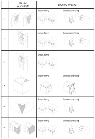
Figure 1.
Main types of failure mechanisms and corresponding typology of provisional shorings.
3. Working Flow of the Proposed Protocol
The protocol that is developed for the safe removal of provisional shorings is defined by the following steps:
- Definition of the preliminary interventions needed to ensure that the wall (or the damaged portion of the building), in its current state, still behaves as a monolithic rigid body. These interventions may be needed because in the time elapsed before the start of the repair/restoration, the masonry may have undergone local disaggregation, destroying the monolithic behavior of the wall.
- Definition of a safety index related to the damaged wall. This index is defined with a procedure that analyzes the wall as an object that behaves like a rigid body subjected to overturning and stabilizing moments.
- Definition of safety levels to be compared to such safety index. The proposed removal procedures depend on the level at which the safety index falls. The definition of these levels is based on the available data related to damaged structures with and without shorings.
- Definition of preventive interventions for the removal of shorings. Two levels of preventive interventions are introduced: mandatory and optional. In different measures, both kinds of interventions reduce the safety index, thus providing the operators of the shoring removal a moderate degree of choice within the protocol to follow for the removal of the provisional shorings.
- Proposal of operations for the safe removal of the provisional shoring depending on the safety level that includes the safety index.
3.1. Preliminary Interventions
The applicability of the method used to evaluate the safety index λ assumes that the wall, or the portion of the building affected by the failure mechanism, still behaves as a monolithic rigid body in its current state. Between the placing of the shorings, which usually takes place immediately after the earthquake, and the moment in which the restoration work start, several years may elapse. In this considerable period, the damaged portions of the structure are affected by environmental conditions and, in some cases, other earthquakes. Such actions may modify the masonry so that the wall or the portion of the building no longer behaves as a rigid body. In general, local disaggregation is the main cause of the loss of monolithic behavior of the damaged portion of the structure. Therefore, often there is an initial need to restore such behavior. In general, for safety purposes, the following preliminary interventions must be implemented before the evaluation of the safety index:
- Visual and/or instrumental non-destructive analysis performed on the masonry of the damaged portion to establish whether a partial or complete disaggregation process occurred;
- Masonry consolidation interventions in areas showing disaggregation phenomena to restore the monolithic behavior of the damaged portion of the structure;
- Placement of sensors and further instrumentation to check the possible increase in the cracks opening during the removal operations of the provisional shorings.
3.2. Evaluation of the Safety Index
The proposed safety index is derived from the failure multiplier already developed in the literature [,]. Such a multiplier represents the horizontal acceleration above which a failure rigid mechanism occurs. Its estimation is performed differently according to the considered type of rigid mechanism (see the middle column of Figure 1). The failure multiplier is obtained under the linear approximation of the rigid kinematics associated with the failure mechanisms and is derived by equating the resisting and overturning moments of the forces acting on the damaged portion of the masonry building. In general, the resisting moments that oppose the development of a failure rigid mechanism depend on the following vertical and horizontal forces:
- Self-weight of all the parts of the building acting on the portion that can manifest a failure rigid mechanism;
- Horizontal resisting static actions due to existing metallic tie rods;
Instead, the overturning moments that contribute to the formation of a failure rigid mechanism depend on the following horizontal forces:
- Seismic inertial forces due to the seismic horizontal acceleration and the mass possessed by the bodies involved in the rigid mechanism. Such forces are proportional to the seismic ground acceleration;
- Horizontal static actions that are transferred to the damaged portion of the building by arches, vaults, and pushing roofs.
It is worth observing that the above seismic inertial forces are the only ones that directly depend on the horizontal seismic acceleration; all of the other forces only depend on the structure characteristics. The failure condition occurs when the resisting and overturning moments are equal. The failure multiplier represents the minimum horizontal acceleration capable of triggering a rigid mechanism of failure. Therefore, a rigid mechanism occurs when the failure multiplier is higher than or at most equal to the experienced seismic acceleration.
Even in the absence of seismic events, when a building undergoes a preventive seismic retrofit, the failure multipliers related to all the possible failure rigid mechanisms should be evaluated. In such a case, the failure mechanisms that may activate are not known a priori and multiple possible failure mechanisms should be studied. The most important part of the seismic retrofit is the one related to the failure mechanism associated with the smallest of the failure multipliers.
The proposed safety index is still evaluated by equating the resisting and overturning moments, as for the failure multipliers, and, as such, represents the minimum horizontal acceleration able to trigger a failure rigid mechanism. However, it is evaluated under the assumption of the knowledge of the type of rigid mechanism that is going to occur. The observation of the cracks on the damaged portion of the structure and the type of provisional shorings used to avoid further damage to the building suggest the type of failure mechanism. Therefore, there is only one safety index associated with each damaged portion of the structure.
It is worth remarking that the evaluation of the safety index is performed disregarding the existence of provisional shorings because the purpose is to evaluate the conditions of the damaged wall when the provisional shorings are removed.
Whatever the type of failure rigid mechanism, the evaluation of the safety index is obtained from a comparison between the resisting moment
and overturning moment
In Equations (1) and (2), is the safety index, representing the horizontal ground acceleration; and are the moments due to self-weight and inertial seismic forces, respectively; is the jth moment due to the static actions of existing metallic tie rods; is a moment due to the static horizontal actions applied by arches, vaults, and pushing roofs. All these contributions are evaluated according to the type of failure rigid mechanism [,]. The safety index is then obtained by equating the resisting and overturning moments. It reads
3.3. Determination of Safety Intervals
Ideally, in order to define the level of the prescriptions needed to ensure the safety of the shoring removal, the best choice would be to fully take into account the damaged state of the structure. Nevertheless, damage assessments may not always be accessible, and in certain instances, they may be derived from sources of questionable reliability. For this reason, the choice of safety level is performed through a normalized version of the safety index. Such a normalized safety index is defined as
where the safety index defined in Equation (3) is divided by a reference value of acceleration . In the most appropriate case, the value should be the maximum value of acceleration experienced by the structure. The rationale behind this choice is that the ratio between the maximum acceleration that the structure can sustain before the activation of failure rigid mechanisms, represented by , and the acceleration experienced by the structure provide a proxy for the damage sustained by the structure. However, since in most cases the acceleration experienced by the structure is not available, the expected value of the maximum acceleration provided by technical standards can be used as a first approximation for , as in this paper.
The four safety intervals (or equivalent risk range) proposed in this paper are defined using the normalized version of the safety index. The width of such intervals is defined by three threshold values: , , and (see Figure 2). Given the scarcity of available data, these threshold values are tentatively assigned and subsequently validated with the results from a set of representative structures for which the formation of failure rigid mechanisms occurred. Table 1 shows the above-mentioned set, containing damaged cases with and without provisional shorings. The fourth column from the left side of Table 1 refers to geometric quantities characterizing the failure rigid mechanism. Specifically, quantity s refers to the thickness of the wall or the portion interested in the failure mechanism; quantity Yg is the vertical height of the mass center of the damaged portion of the structure, measured from its lowest point (typically the plastic hinge line); A is the area of such damaged portion. It is worth noticing that the mean values of the safety indexes (i.e., without any preventive prescriptions) and (i.e., with only the mandatory preventive prescriptions, see Section 3.4) show that the mandatory prescriptions increase the value of the safety index, thus showing the safer conditions of the structures after the application of such mandatory prescriptions.
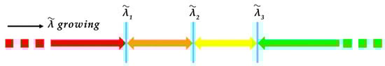
Figure 2.
Safety intervals.

Table 1.
Damaged cases.
In Figure 2, the values , , and are the threshold values to be compared with the nondimensional safety index . The safest level for the structure is associated with values because in this case, the structure experienced a maximum acceleration lower or at most equal to the one for which it has been designed. As the value diminishes, the acceleration able to activate a failure rigid mechanism is lower than the expected (or experienced) seismic acceleration, thus theoretically entailing a higher damage level.
In order to compare the proposed choice of safety intervals with the available cases and understand what the consequences of such a choice would be for the test samples presented in Table 1, a distribution for the normalized safety index of such cases is first fitted. This fitting is based on the assumption that the considered cases are representative of the masonry building inventory of the analyzed area. Figure 3 illustrates a selection of distributions considered for data fitting, accompanied by the normalized histogram representing the empirical probability density function (PDF) of the data. Notably, even in the absence of data points with a value greater than 2, unbounded distributions have also been explored, given the absence of a priori grounds to assume the non-existence of such scenarios.
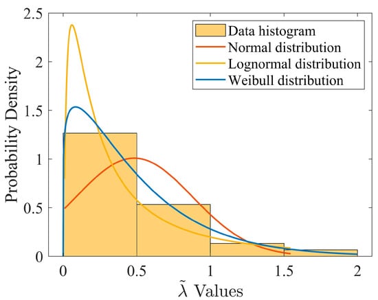
Figure 3.
Normalized histogram of normalized safety index for the test cases.
This fitting is based on the assumption that the considered cases are representative of the masonry building inventory in the analyzed area. For comparison purposes, the fitted distribution is overlaid on the chosen intervals. As hinted above, the value considered herein is the expected maximum acceleration provided by the technical standard [], .
When compared to the normalized histogram of the data, the fitted Weibull distribution (blue curve in Figure 3 and Figure 4) seems to provide a better fit for the data. Figure 4 presents the fitted probability density function for this distribution along with the suggested safety intervals and the normalized safety factors for the sample cases. These cases are categorized based on the presence or absence of provisional shorings, represented by purple and green dots, respectively. Assuming that the sample selection accurately represents the masonry building inventory in the analyzed area, the fitted Weibull distribution quantifies the probability of a masonry building in the area having a specific . Furthermore, the region beneath the probability density functions, bounded by two successive threshold values (), signifies the proportion of masonry buildings expected to fall within the safety interval defined by those two .
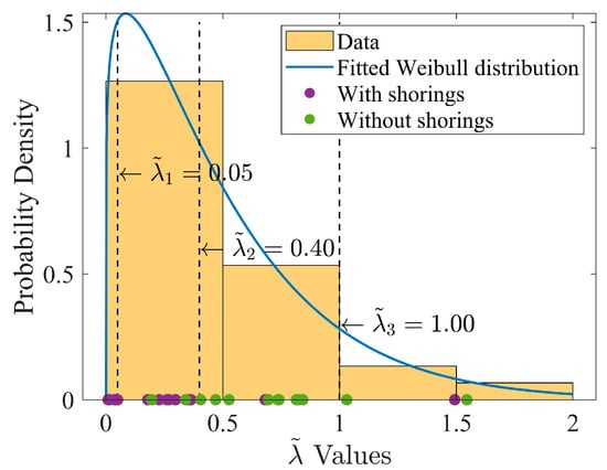
Figure 4.
Comparison between test cases and chosen safety intervals.
Figure 4 shows that, according to the chosen safety intervals, the majority of the cases with provisional shoring (purple dots) are included in the first two safety intervals; while the majority of the cases without provisional shorings (green dots) are classified in the third and fourth intervals. In both cases, there are two exceptions. Additionally, it can be seen that the first interval, although relatively narrow, includes a significant number of cases, all of which involved shorings. Comparing the fitted distribution with the interval thresholds—given that the median value of the fitted distribution is approximately 0.37—slightly more than 50% of the masonry structures would be categorized in the first two safety intervals, and the first interval would contain about 7% of the masonry structures.
While yielding satisfactory results, the determination of safety interval thresholds in this paper is constrained by limited available data and damage assessments. Future studies could enhance the definition of these thresholds by expanding the dataset to encompass a broader range of cases from various regions with distinct seismicity levels, potentially induced by different earthquakes.
3.4. Preventive Interventions
The developed method is sufficiently versatile to allow a certain degree of choice to the operators involved in the process of shoring removal. Specifically, different choices of preventive interventions correspond to different values of the safety index . Such choices can be selected from among the optional preventive interventions (that could be performed in addition to the mandatory ones), which affects directly the value of and, consequently, the value of .
Mandatory preventive interventions are all the operations that must be performed on-site before starting the removal of provisional shorings. Such interventions aim to reduce the uncertainties in the calculation of the safety index and to increase the safety of the construction site. The mandatory interventions and the reasons for which they have been suggested are listed below:
- Removal of existing metallic tie rods. This intervention stems from the assumption that if the portion of the building has suffered damages, the metallic tie rods malfunctioned or are damaged. Even if the metallic tie rods are not physically removed, they should not be considered in the evaluation of the safety index. Assuming them to be functional would go against safety. It is worth observing that as far as the safety index is concerned, such a removal corresponds to vanishing the term depending on in Equation (3). This fact provides a reduction in the value of the safety index and, consequently, an increase in the risk level. It is important to note that these metallic tie rods were already in place within the buildings prior to the seismic events and prior to the installation of temporary shoring.
- Prevention of horizontal actions due to arches, vaults, and pushing roofs. Such horizontal actions increase the overturning moment of the damaged portion of the building, and their effects are independent of the occurrence of seismic events. The elimination of horizontal actions can be achieved by assembling temporary metallic tie rods in arches or vaults, which can also become permanent if compatible with the restoration design. The effects of pushing roofs can be neglected by disassembling the roof before the removal of the provisional shorings. It is worth observing that such actions mathematically correspond to vanishing the term depending on in Equation (3), thus providing an increase in the safety index and a general reduction in the risk level.
The optional preventive interventions are intended to provide the versatility mentioned above. The operators involved in the procedure of shorings removal can choose the type and number of optional interventions before proceeding with the removal of provisional shorings. The optional interventions and the various combinations among them affect the value of the safety index, increasing the value of from the one obtained without considering any preventive intervention. The optional preventive actions and the reasons for which they have been suggested are discussed below:
- Installation of vertical shoring below floors and/or vaults if they are not present. This intervention reduces the load on the wall or the portion of the building that has shown a failure mechanism. This intervention generally produces a decrease in the safety index because it vanishes the stabilizing contribution of the self-weight of floors and vaults, whereas the contribution to the overturning due to the horizontal inertial seismic effects remains unchanged. Evaluating the safety index with and without the internal vertical shoring provides an indication of the convenience of restoring floors and vaults (with the consequent removal of the vertical shorings) before removing the external shorings.
- Demolition of floors and/or vaults. This preventive intervention eliminates both gravitational stabilizing forces and seismic inertial overturning forces. For the vaults, the demolition also vanishes the static horizontal forces that increase the overturning moments independently from the seismic actions. In general, since the inertial contribution to the overturning is larger than the stabilizing contribution due to self-weight, this intervention produces an increase in the safety index. If their demolition is included in the seismic restoration design, then this preventive intervention is highly suggested. In general, demolishing registered buildings designated as cultural heritage is not permissible.
4. Tool for the Evaluation of the Safety Index
A tool to evaluate the safety index (including preventive interventions or not) has been developed in the MS Excel environment. Such a tool is constituted of MS Excel sheets in which the input needed to evaluate the safety index should be provided. Each type of failure rigid mechanism (see Figure 1) requires a different sheet. The input data are the geometrical and mechanical characteristics of the portion of the masonry building involved in the failure rigid mechanism. Due to the simplicity of the required input data, even operators with moderate specialization can evaluate such a risk index. The sheet includes the formulation needed to automatically evaluate the resisting and overturning moments (see Equation (3)) from the input data and provides eight different values of the safety index. Specifically, the eight values and ( = a, …, g) refer to different combinations of mandatory and optional preventive prescriptions. The safety index (as in Table 1) refers to the case with no preliminary interventions and, consequently and coincides with the collapse multiplier in [,]. The definitions of the other seven safety indexes ( = a, …, d) are shown in Table 2:
Table 2.
Safety index legend.
The simultaneous knowledge of the safety index evaluated for different cases helps the operators of the shorings removal in the choice of preventive interventions and can suggest a better strategy for the removal of provisional shoring according to the characteristics of the construction site, thus decreasing the risk level of the removal. Figure 5 qualitatively shows the intended effects of the preventive interventions on the safety index. In general, the mandatory and optional preliminary interventions reduce the value of the safety index; therefore, the safety index computes disregarding the preventive intervention falls in a lower safety level. The operator of the shoring removal can choose the combination of interventions that correspond to the largest reduction of the safety index (minimizing the risk level) or a different combination where the interventions better conform to the restoration design.
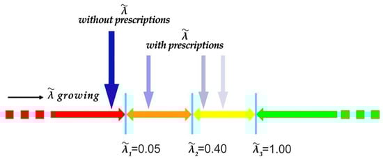
Figure 5.
Effect of mandatory and optional prescriptions on the safety index .
5. Removal Operations of Shorings
The execution of removal operations hinges on the safety interval (risk range) in which the safety index of the specified section of the structure lies. This section pertains to the conclusive evaluation of the safety index, already factoring in the decision to carry out specific preventive interventions. A brief description of the suggested general removal operations is provided below as a function of the safety interval. It is worth observing that detailed removal operations cannot be suggested due to the inherent differences among construction sites, buildings, and typologies of shorings.
5.1. Red Interval
In the worst-case scenario, even after the preventive interventions the safety index falls within the lowest safety level, the red one in Figure 2. This is the case with the higher risk of collapse of the structure and, as such, the provisional shorings cannot be removed before some repair/restoration operations have been performed. In this case, the restoration design must be scheduled as initial operation, needed for the repair of the portion of the structure related to the rigid mechanism.
If the provisional shorings interfere with the construction site organization and repair operations, preliminary stitching of the main crack lines of the damaged masonry must be performed. The choice of the stitching method is a prerogative of the designer and depends on the masonry typology and its state of conservation. The details of this choice, which is indeed important, fall outside the objectives of this paper. Finally, it is fundamental that the monitoring system described in Section 3.1 is maintained operational until the end of the complete repair/restoration of the damaged portion of the structure that is being considered.
5.2. Orange Interval
If the safety index falls within the orange interval (see Figure 2), great attention must still be paid to the removal of the provisional shorings. Even if, after the preventive interventions, the safety index falls within the orange interval, such preventive interventions should be performed because they still reduce the risks associated with the restoration works. In this case, partial removal of the shorings can be planned. For example, in the case of tensile shorings, it is reasonable to reduce the number of provisional tensile stripes or steel metallic tie rods. If the restoration works can be conducted at different times for different levels of the building, shorings should be removed only at the level subject to the restoration intervention, maintaining operational both the shorings at the other levels and the monitoring safety system.
5.3. Yellow Interval
Most of the damaged cases that did not require provisional shorings after the earthquake fall inside the yellow interval (see Figure 2). Therefore, the yellow interval is associated with a relatively low risk level. However, the uncertainties related to the restoration interventions (e.g., partial demolition of sections of the building) advise caution. The total removal of shoring should be performed over time as the restoration interventions advance so that the operators can observe the behavior of the damaged portion of the structure through the installed monitoring system. Moreover, the removal of the shorings for the case in which the safety index falls with the orange interval (see Section 5.2) should be gradual with a progressive reduction of the number of shorings.
5.4. Green Interval
If the safety index falls in the green safety interval (see Figure 2), the provisional shoring can be fully removed at the beginning of the restoration interventions. However, since the building has suffered damage due to earthquakes and caution is always required during the removal operations, the monitoring system should be kept operational during the entire duration of the restoration interventions to warn of unforeseen dangerous situations.
6. Methodology for the Removal of Provisional Shorings
This section describes the proposed steps suggested as good practices for the safe removal of provisional shorings. Starting from the assumption that the provisional shoring used in the building is in proper condition and efficientwhen the restoration operations start, a procedure for the full removal of the provisional shorings is described below with an example.
6.1. Description of the Building Object of the Validation
The use of the proposed tool is showed using as an example the provisional shoring of Palazzo Carli, a building owned by the Italian University of L’Aquila, located in the city’s historic center.
Palazzo Carli is located on the main decumanus of Via Roma that connects the western part of L’Aquila to the historic center and has its main entrance on Piazza Dell’Annunziata. The building complex has a morphological layout characterized by the classic system of courts around which spaces and volumes are structured. It is configured as the result of several recasting processes to which, over time, the building organism has been subjected and which have led to updating the spatial and distributive system of the building several times.
The original typological characteristics of the palazzo can still be seen in the 18th-century portion, which features the traditional hall–courtyard–staircase distribution scheme. The other portions of the building, modified over time, have been profoundly transformed both with respect to the original features of the layout and the general conformation.
The construction of the building, according to literary sources, dates back to the first half of the 16th century, and the oldest portion of Palazzo Carli is the one located on Via Roma, while the current architectural structure can be traced back to the mid-18th century. Analyses of the direct sources confirm that what emerged from the historical sections, i.e., that Palazzo Carli today is the result of continuous remodeling that can be read on different fronts. The original façade on Via Roma presents the perspective layout characterized by 16th-century openings and two portals, the oldest of which dates back to the 16th century; the one on Piazza dell’Annunziata refers to the original 18th-century structure; the façades on Via Forcella and Via del Pavone are instead the result of interventions between 1959 and 1966 that produced heavy renovations inside the original building.
The technological layout of the building complex is characterized by great heterogeneity, with construction elements and materials closely related to the historical period in which they were altered following the seismic events of 1703 and 1915 and due to changes in use. The original load-bearing structure, mainly made up of L’Aquila’s limestone ashlar masonry, is organized according to a regular geometric mesh woven in the two directions of the plan. The horizontal closures are made up of different types of resistant elements: on the first levels by concrete vaults configured as barrel or pavilion vaults and on the upper floors by thin floors with metal beams and brick blocks, introduced into the complex in the early 20th century. In the southern area of the building, there are hollow-core concrete floors, supported by a system of frames woven longitudinally and placed in adherence to the ancient walls. Finally, heavy renovations were also carried out on the building in the 1960s, which led both to the emptying out of parts of the complex with subsequent incongruous reconstructions in reinforced concrete and to the insertion of new structures, always using the same type of material. This technological mixture, which came to light after the 2009 earthquake, shows all the incongruous functioning of the construction system already revealed through the reading of the building’s figurative and spatial system, now characterized by an architectural structure devoid of its original character. The damage to the masonry portions, the collapses, and the kinematics created by the earthquakes have further accentuated the inadequate seismic behavior of the entire building complex.
Similar to Palazzo Carli, in L’Aquila, a significant number of historic public buildings damaged by the earthquake lack a coordinated project for the removal of temporary shorings, which should ideally be synchronized with consolidation and restoration efforts. Moreover, in many cases, these buildings also lack a comprehensive survey of their shoring systems. It is evident that this gap in knowledge and awareness could lead to inefficiencies, delays, and potential hazards during the execution of the restoration works.
6.2. Procedural Steps
The façades of Palazzo Carli on Via Roma and Piazza D’Annunziata, due to the earthquake of L’Aquila 2009, have been affected by a double failure rigid mechanism:
- Cantonal rollover mechanism (see no. 5 in Figure 1, Figure 6a, green line in Figure 7). Composed tilting mechanism of the façade on Via Roma (see no. 6 in Figure 1, Figure 6b, red line in Figure 7).
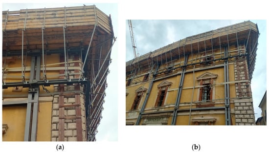 Figure 6. Palazzo Carli, double failure rigid mechanism: (a) cantonal rollover mechanism; (b) composed tilting mechanism.
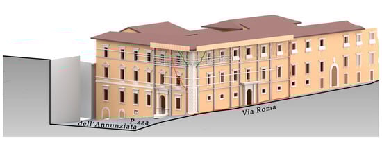 Figure 7. Palazzo Carli, with the detected provisional shoring system and the main crack lines (green line: cantonal rollover mechanism; red line: composed tilting mechanism of the façade).
To contrast these mechanisms, three types of shoring systems have been inserted: hoops, jackets, and anti-fall propping of the roof (see pictures in Figure 6). In this paper, only the composed tilting mechanism of the façade is considered for this case study. To illustrate the proposed methodology and tool, a building information modeling (BIM) model of Palazzo Carli was constructed. Figure 7 displays a rendered image of Palazzo Carli alongside the identified provisional shoring system, which was employed to secure the investigated failure mechanisms affecting the façade.
The main steps for the safe removal of the provisional shorings are discussed below, and Figure 8 shows the flow chart of their application.
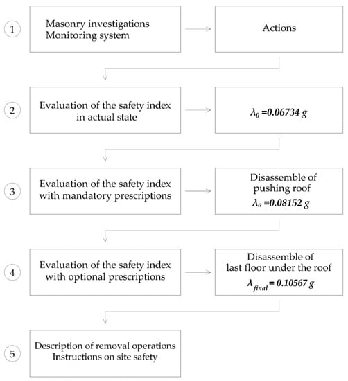
Figure 8.
Flow chart of the methodology on the case of study, where numbers indicate the order of execution of each step.
- Step 1. Preliminary interventions: The visual inspection performed on the masonry of the damaged portion resulted in no observed partial or complete disaggregation of the masonry. Therefore, no consolidation interventions on masonry are needed.
A monitoring system is prescribed to provide real-time information regarding the opening of the cracks. About ten analogic, low-cost extensometers should be distributed along the main crack lines of the damaged façade, and three inclinometers should be placed on the damaged wall.
- Step 2. Evaluation of the safety index in the actual state: The safety index is evaluated without considering the presence of the provisional shoring; the evaluation provides . This value falls inside the orange safety interval (see Figure 5).
- Step 3. Evaluation of the safety index with the mandatory preliminary interventions: The damaged wall is subject only to the horizontal static action of the pushing roof. As a preliminary mandatory intervention, the disassembly of the roof is then required (see Figure 9). The consequent value of the safety index is . This value still falls inside the orange safety interval (see Figure 5).
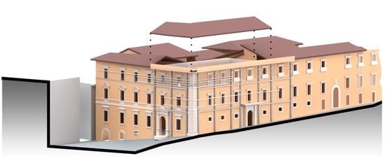 Figure 9. Mandatory prescriptions: disassemble the pushing roof.
 - Step 4. Evaluation of the safety index with the optional preliminary interventions: As in the restoration design, the disassembly of the last floor, just below the roof, is required as a preliminary operation before the removal of the provisional shorings (see Figure 10). The consequent final value of the safety index is . The required optional intervention allows the safety index to fall inside the yellow safety interval (see Figure 5).
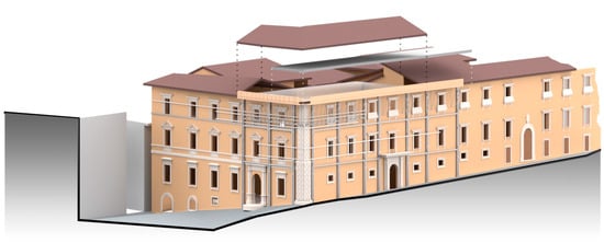 Figure 10. Optional prescriptions: disassemble the floor just below the roof.
 - Step 5. Description of the removal operations: The shoring removal should be performed over time, as the restoration interventions advance, so that it is possible to observe the behavior of the damaged portion of the structure through the installed monitoring system. To reduce the risk of further damage and structural collapse, it is advised to proceed with a gradual reduction of the number of shorings that affects the whole building.
Additional instructions regarding the general safety of the construction site must be provided. Such instructions depend on the characteristics of the building and the designed restoration interventions and cannot be generalised.
7. Conclusions
Due to the recent seismic events that affected Italy (L’Aquila 2009, Central Italy 2016), masonry building heritage suffered relevant damages. Several types of post-seismic provisional shorings were extensively used. The primary aim of these safety provisional interventions was to ensure safe conditions for debris removal and road rehabilitation prior to the commencement of restoration efforts. Several studies concerning the typology and assembly of post-seismic shorings can be found in the literature. However, up to now, the aspects related to the disassembly of such shorings—which strongly impact the repair process of damaged structures from a safety, organizational, and economic point of view—have been neglected. In this paper, the proposal of an operating protocol for the safe removal of provisional shorings was proposed. Such a protocol includes three fundamental steps: (i) development of a risk assessment tool that provides a safety index and does not require a high specialization of the operators to use the tool; (ii)definition of safety levels based on available samples of damaged masonry buildings; (iii) definition of the site operating protocol depending on the safety level in which the safety index falls. Additionally, preliminary and preventive interventions were proposed. For safety purposes, the preliminary interventions must be implemented before the evaluation of the safety index. Instead, the preventive mandatory and optional interventions and their combinations assure versatility to the method, granting a degree of discretion to the operators engaged in the removal operations.
The effectiveness of the proposed methodology was demonstrated through its application to a masonry building in L’Aquila. The procedure exhibited simplicity and robustness and yielded favorable outcomes for the specific case study. According to the authors, this methodology can be deemed valuable for ensuring the safe management of construction sites and the removal of provisional shorings. It is crucial to note, however, that all operations outlined in this paper must always be supplemented by standard construction site safety protocols, which are not explicitly detailed herein.
This study is subject to several limitations, which can be outlined as follows. Firstly, the existing literature on this subject is notably sparse, as underscored in the state-of-the-art analysis. Consequently, the study lacks the benefit of comparison with the work of other researchers. Additionally, the analytical framework relies on a limited number of case studies, warranting further expansion. Lastly, obtaining a significant number of construction sites for protocol validation is essential; however, this requirement can sometimes face resistance from contractors and site technicians.
Conversely, the conducted research holds significant potential for impact. Its applicability extends to all earthquake-prone regions and can influence various post-disaster scenarios involving shoring. This encompasses not only streamlining and enhancing the safety of construction efforts but also fostering virtuous cycles of element reuse in provisional works.
Author Contributions
Conceptualization, M.R., A.D.E. and P.D.B.; Methodology, M.R. and A.D.E.; Validation, G.D., A.D.E., M.R. and A.C.; Formal analysis, A.D.E. and M.R.; Investigation, G.D. and A.D.E.; Writing—original draft, A.D.E., M.R., G.D. and A.C.; Writing—review & editing, A.D.E., M.R., G.D. and A.C.; Funding acquisition, M.R. and P.D.B. All authors have read and agreed to the published version of the manuscript.
Funding
The paper was partially supported by funds provided by FORMEDIL through a convention with the University of L’Aquila, Italy, DICEAA Department (Scientific Responsible M.R.), born as a result of an agreement signed in 2019 between the National Council of Engineers (CNI), and CNCPT, a company dedicated to the training and safety of workers, which was joined in 2022 by the DICEAA Department and the Interregional Superintendency for Public Works for Lazio, Abruzzo, and Sardinia for the definition of a protocol for the safe removal of shoring works carried out following the seismic events that occurred in L’Aquila in 2009.
Data Availability Statement
Not applicable.
Conflicts of Interest
The authors declare no conflict of interest.
References
- Modena, C.; Da Porto, F.; Filippo, C.; Munari, M.; Simonato, E. Cultural Heritage Buildings and the Abruzzo Earthquake: Performance and Post-Earthquake Actions. Adv. Mater. Res. 2010, 133–134, 3–17. [Google Scholar] [CrossRef]
- Modena, C.; Valluzzi, M.R.; da Porto, F.; Casarin, F.; Garbin, E.; Munari, M.; Mazzon, N.; Panizza, M.; Dalla Benetta, M. Recent advances in the structural analysis and intervention criteria for historic stone masonry constructions subjected to seismic actions. In Proceedings of the ISCARSAH Symposium Mostar, Mostar, Bosnia and Herzegovina, 9–12 July 2009. [Google Scholar]
- Miltiadou-Fezans, A.; Tassios, T.P.; Delinikolas, N.; Chorafa, E.; Zarogianni, E. Earthquake structural problems and urgent measures undertaken to support the Katholikon of Dafni Monastery in Athens, Greece. In Proceedings of the Eighth International Conference on Structural Studies, Repairs, and Maintenance of Heritage Architecture, Chilworth, UK, 7–9 May 2003. [Google Scholar]
- Zbranca, I. The importance of temporary structures and consolidation in the preservation of old buildings. Eur. J. Sci. Theol. 2013, 9, 209–214. [Google Scholar]
- Kim, J.; Fischer, M. Formalization of the features of activities and classification of temporary structures to support an automated temporary structure planning. In Proceedings of the Computing in Civil Engineering; 2007; pp. 338–346. Available online: https://ascelibrary.org/doi/abs/10.1061/40937%28261%2942 (accessed on 27 June 2023).
- Jiang, J.; Ye, K. Construction method and dismantling process analysis of temporary shoring structure for the roof of Shanghai New International Expo Center. Jianzhu Jiegou Xuebao/J. Build. Struct. 2006, 27, 118–122. [Google Scholar]
- Langenbach, R.; Dusi, A. On the cross of Sant’Andrea: The response to the tragedy of San Giuliano di Puglia following the 2002 Molise, Italy, earthquake. Earthq. Spectra 2004, 20 (Suppl. 1), S341–S358. [Google Scholar] [CrossRef]
- Cifani, G.; Castellucci, A.; Lemme, A.; Liris, M.; Martinelli, A.; Mazzariello, A.; Milano, L.; Morisi, C.; Petracca, A.; Marchetti, L.; et al. 2011 SISMA ABRUZZO 2009—Messa in sicurezza degli edifici monumentali: Percorso, metodologia e tecniche di intervento. In Proceedings of the XIV Convegno ANIDIS L’Ingegneria Sismica, Bari, Italy, 18–22 September 2011. (In Italian). [Google Scholar]
- Grimaz, S. SYTOP—Schede Tecniche Delle Opere Provvisionali per la Messa in Sicurezza Post-Sisma da Parte dei Vigili del Fuoco. 2010. Available online: https://www.ahrcos.it/pdf/puntellature/puntellature.pdf (accessed on 15 September 2023). (In Italian).
- Liberatore, D.; Mattera, M.; Perillo, G. Opere provvisionali post-sisma per edifici in muratura. In Proceedings of the XIII Convegno ANIDIS “L’Ingegneria Sismica in Italia”, Bologna, Italy, 28 June–2 July 2009. [Google Scholar]
- Civerra, C.; Lemme, A.; Cifani, G. Strumenti per il Rilievo del Danno e Della Vulnerabilità Sismica Dei Beni Culturali; Tipografia Lampo: Campobasso, Italy, 2007. [Google Scholar]
- Milano, L.; Mannella, A.; Morisi, C.; Martinelli, A. Schede Illustrative dei Principali Meccanismi di Collasso Locali Negli Edifici Esistenti in Muratura e dei Relativi Modelli Cinematici di Analisi. Allegato Alle Linee Guida per la Riparazione e il Rafforzamento di Elementi Strutturali, Tamponature e Partizioni. 2009. Available online: http://www.geostrutture.eu/images/download/ministero/reluismeccanismi.pdf (accessed on 27 June 2023). (In Italian).
- Beolchini, G.C.; Milano, L.; Antonacci, E. Repertorio dei Meccanismi di Danno, Delle Tecniche di Intervento e dei Relativi Costi Negli Edifici in Muratura Volume ii—Parte 1. Convenzione di Ricerca con la Regione Marche; Definizione di Modelli per L’Analisi Strutturale degli Edifici in Muratura; Consiglio Nazionale delle Ricerche; Istituto per la Tecnologia delle Costruzioni; Sede di L’Aquila; Dipartimento di Ingegneria delle Strutture, delle Acque e del Terreno (DISAT); Università degli Studi di L’Aquila; Tipografia Grafiche Scarponi S.r.l.: Osimo, Italy, 2007. (In Italian) [Google Scholar]
- NTC2018; Nuove Norme Sismiche Per il Calcolo Strutturale. Italian Technical Building Codes. D.M.: Roma, Italy, 2018.
Disclaimer/Publisher’s Note: The statements, opinions and data contained in all publications are solely those of the individual author(s) and contributor(s) and not of MDPI and/or the editor(s). MDPI and/or the editor(s) disclaim responsibility for any injury to people or property resulting from any ideas, methods, instructions or products referred to in the content. |
© 2023 by the authors. Licensee MDPI, Basel, Switzerland. This article is an open access article distributed under the terms and conditions of the Creative Commons Attribution (CC BY) license (https://creativecommons.org/licenses/by/4.0/).