Abstract
Detecting intrusion in hazardous areas is one of the priorities and duties of safety enhancement. With the emergence of vision intelligence technology, hazardous-area-detection algorithms can support safety managers in predicting potential hazards and making decisions. However, because of the dynamic and complex nature of the jobsite, high-risk zones have a different geometry and can be changed following the schedule and workspace of activity. This leads to hazardous areas being annotated manually. Thus, this study proposes a computer vision and a 4D BIM-based approach for intrusion detection in hazardous areas, called IDC4D. IDC4D comprises three modules: (1) the 4D BIM-based safety planning (4BSP) module, which analyzes the hazardous area; (2) the hazardous area registration (HAR) module, which delivers the hazardous area from the BIM model to the camera’s first frame image; and (3) the hazardous-area-intrusion-detection module (HAID), which applies the computer vision algorithm to identify the correlation between workers and hazardous areas. The efficiency of the IDC4D approach is validated by testing a maintenance project on the construction site. IDC4D supports the planner in choosing the plan and detecting the event of workers entering hazardous areas while working. It showed an average precision of 93% and 94% in phase 1 and phase 2, respectively. These findings provide insight into how varying geometries of diverse hazard areas can be handled for enhancing intrusion detection.
1. Introduction
Worldwide, the construction industry is recognized as the most dangerous industry in terms of accidents on the jobsite, leading to a significant loss of life and property [1,2]. According to Occupational Safety and Health Administration (OSHA) data [3], the construction sector accounted for 1008 deaths in 2020, with falls from heights accounting for approximately 33% of the fatalities. Moreover, South Korea’s construction industry was responsible for more than half of all industry-wide fatality incidents [4]. The construction industry in Europe has the third highest rate of nonfatal injuries, with the accident rate being higher than the average for all industries [5]. This not only decreases the quality of life of those injured and their families, but also damages the environment. Research has demonstrated that a safe workplace can lower accident occurrence [6,7,8,9]. Potential hazardous zones should be identified during the planning phase, and intrusion should be detected and monitored during the construction phase. Such information can assist safety managers and stakeholders in identifying and preventing potential hazards.
To detect intrusion in hazardous areas, identifying the distance correlation between site employees and hazardous areas is foundational of algorithms [10], even if applying sensing technology or computer vision in place of manual inspection: (1) Sensing technologies utilize signal-processing methods such as ultra-wideband, Bluetooth Low Energy, radio frequency identification, and ZigBee to detect or proximate the distance between other sensor tags. They can be applied to monitor the interactions between on-site person positions and other entities, such as equipment, on-site persons, and temporary facilities, on the construction site. In other words, on-site persons wearing sensor tags could be warned when approaching a hazardous area fitted with another sensor tag. For instance, using Bluetooth technology, Park et al. [11] presented a range-detection and alarm system for dangerous proximity scenarios between highway construction on-site persons and construction vehicles. Jin et al. [10] explored the use of an RFID sensor attached to a hardhat and a portable RFID trigger installed in potentially hazardous working spaces, such as openings. (2) The computer vision technique analyzes the visual data collected from the surveillance systems to automatically detect jobsite entities by utilizing deep-learning algorithms. To prevent hazardous-area entry, Fang et al. [12] developed deep-learning algorithms to detect the structure supports and on-site persons and evaluated the relationship between them. Khan’s approach [13] involved utilizing computer vision to detect the interaction between scaffolding and the on-site person to determine whether the working height was within Korea Occupational Safety and Health Agency (KOSHA) regulations. Researchers have also focused on developing algorithms to detect jobsite entities and their relationships.
A proper hazardous area identification would improve intrusion-detection quality. This is a typical geometry annotation problem in which the aim is to enhance the defining of hazardous areas. Due to the dynamic nature and complexity of construction jobsites, the hazardous areas corresponding to the specific entities defined in the regulations have different geometries and sizes. The geometry varies across different potentially hazardous areas in construction jobsites, such as floor openings, excavation holes, and the area around the scaffolding [14], etc. According to the use of sensor technologies, the active zones of the sensor tag are spherical coverage areas due to the signal processing involved. These necessitate installing numerous sensor tags according to the type of monitored entity. Moreover, during the construction phase, the hazardous area in the same workspace may be changed by shifting to different activities as per the schedule. Hence, the on-site persons have to reinstall the sensor tags for different purposes. For instance, the hazardous area during the excavation phase is the excavation holes. Afterward, when preparing foundation work, safety managers have to consider the hazard posed by the foundation pit area or pile foundation area. Furthermore, current computer vision methods also face challenges in annotating hazardous areas in the intrusion-detection process. The presence of diverse and complex dangerous regions on construction sites is a significant problem as they encounter difficulties in accurately detecting and encompassing a wide range of hazardous areas [15]. Mei et al. [16] labeled the hazardous area manually with the help of image-annotation tools. However, manual labeling faces the challenge of measuring the geometry in a 2D image based on the size of the pixels.
Building information modeling (BIM) has been shown to improve occupational safety, for instance, by facilitating accurate site layouts and safety plans, applying cutting-edge methods for visualizing existing designs, the acquisition of spatial–temporal information, and safety communication [6,17,18,19,20]. Thus, project teams can glean helpful information for furthering the aims of the project. For instance, safety managers may design a safety plan to avert dangers in the workspace, schedule information, and characterize the construction jobs. In addition, more information may be incorporated into the BIM model throughout the building phases for various purposes [20,21,22,23]. Tran et al. [24] proposed the development of a computer-vision-based automatic safety status updating with the support of BIM information. In addition, the 4D-BIM model can provide the geometric information needed, such as the hazardous area boundaries during the period extracted from the schedule. The geometric information from BIM can be transformed as input for applying another technique, for instance, hazardous area object annotation in computer vision.
To solve the above-mentioned challenges of intrusion detection in hazardous areas, this study incorporates computer vision technologies and 4D BIM to develop the IDC4D approach. The objective of IDC4D is to support safety managers in determining the correlation between on-site persons and the hazardous area for monitoring and warning during construction. To perform this, three modules of IDC4D are proposed, including the 4D BIM-based safety planning module (4BSP), which analyzes hazardous area, the hazardous area registration module (HAR), which delivers the hazardous area from the BIM model to the camera’s first frame image, and the hazardous area intrusion detection module (HAID), which applies the computer vision algorithm for identifying the correlation between on-site persons and the hazardous area. This research makes three main contributions:
- Considering geometric information of the hazardous areas from the BIM model, which is defined through a rule-based model from the plan, then extracting and transforming it into objects for supporting the vision monitoring system.
- The IDC4D also considers the construction schedule through dividing phases during the construction process. Accordingly, the hazardous area in the field of view of a virtual camera can be transformed into a suitable object before construction.
- The prototype system was developed to validate the IDC4D, and the results show the efficiency of IDC4D supported the planner in selecting a plan and detecting the event of on-site persons entering hazardous areas below the scaffolding work.
The remaining parts of the article are organized as follows: after this introduction, Section 2 reviews the present status of safety monitoring and intrusion detection in construction, together with BIM coupled with computer vision. The technique for detecting intrusions into hazardous areas that have been suggested is discussed in Section 3. Section 4 presents a comprehensive breakdown of the development and validation of the IDC4D prototype. In Section 5, we discuss the substantial advances in research and its limits. In the final section, the findings and their potential future applications are summarized.
2. Literature Review
2.1. Preventing Entry to Hazardous Areas on Construction Jobsites
Safety is essential at every construction jobsite, which is indicated in laws/regulations such as section 292 of subsection 6.4 of the Model Work Health and Safety Regulations in Australia, Act 85 of 1993 in South Africa, and Section 29 CFR 1910.120(b) of the OSHA regulations in the United States. However, the project employees practically fail to follow safety guidelines, including entering hazardous areas that lead to incidents at job sites. The theory of task dynamics, proposed by Winsemius [25], can help to explain why some project employees may be more prone to intrusion behavior at construction sites, as they are likely to weigh the convenience of a quicker route against the potential risks of entering a hazardous area and underestimate the possible consequences of their actions. Hence, safety professionals need to be aware of this tendency and take steps to prevent construction on-site persons and other individuals from engaging in risky behaviors at the jobsite. Therein, providing clear guidance on safe practices and procedures is required. For instance, in the trench safety infographics, the Center for Construction Research and Training (CPWR) recommends keeping rocks, soil, materials, and equipment away from the edge of the trench. This would shape the hazardous zone around the trench, which the safety managers should consider to practice trench safety [26]. Moreover, there is a need for monitoring on-site persons at workplaces associated with hazardous areas during the construction phase.
Construction safety monitoring is critical in recognizing and warning of potential hazards to prevent unacceptable intrusion. Site observations and inspections have traditionally been utilized as monitoring tools in the construction industry to evaluate the dangers involved in ongoing works and existing site conditions [27]. However, these systems are expensive, and using them is time-consuming because supervisors or safety staff have to perform visual inspections and write down their findings. Manual inspection also has drawbacks, such as a lack of timely access to comprehensive and accurate information. Detecting dangers, such as risky situations and activities, depends on the observer’s capacity to see and comprehend the scenario.
As listed in Table 1, Xu et al. [28] investigated the benefit of smart sensing technologies and integrated them with manual inspection to develop collaborative safety monitoring. In preventing hazardous-area entry, Kanan et al. [29] proposed a sensing approach for preventing site laborers who work within hazardous zones. Shuang et al. [30] considered age and gender variables that affected the intrusion behavior of 147 laborers over four months on construction jobsites. To conduct the experiment, the authors utilized sensing technologies for location tracking combined with BIM. In Jin’s proposed solutions [10], an RFID sensor mounted to a hardhat and portable RFID trigger is placed in potentially dangerous working places. However, using sensing technologies, such as RFID sensors, to prevent hazardous area entry has limitations. (1) Reliability: Sensing technologies may not always work as intended due to interference, malfunctions, or maintenance issues. This can lead to false alarms or missed detections, compromising the system’s effectiveness. (2) Limited Range: Sensing technologies may be restricted, making them unable to identify objects or individuals beyond a specific distance. Additionally, the active zones encompass spherical coverage regions because of signal processing. In contrast, building sites have diverse forms and geometries that might provide hazards, such as apertures, excavation pits, and the vicinity around scaffolding. (3) Cost: Implementing and maintaining a sensing system can be expensive, especially if it requires installing and maintaining many sensors or other devices. (4) Convenience: The hazardous area inside the workstation may undergo modifications during the construction phase because of transitioning to different activities according to the predetermined timetable. Accordingly, the on-site persons have to re-install the sensor tags for different purposes.

Table 1.
Intrusion detection in hazardous areas in the construction domain.
2.2. Intrusion Detection in Hazardous Areas Based on Computer Vision
Vision intelligence technology is also a trend that academic and industry professionals have also studied and implemented vision intelligence technology for the automated detection of individuals entering hazardous areas at construction sites, as listed in Table 1. Deep learning algorithms have been developed based on specific scenarios from expert knowledge and regulations, then deployed into the monitoring system to support stakeholders in identifying potential hazards of its scenarios. Studies have developed an approach for detecting unsafe behavior from the distance correlation between entities. For instance, Khan’s approach [13] applied computer vision to detect the relationship between the scaffolding and the on-site person to determine whether their working height was higher or lower than KOSHA stipulated. Kim et al. [33] presented a method for measuring the distance between employees and other construction entities using YOLO-V3.
Similarly, hazardous areas have to be identified before analyzing the distance correlation between them and on-site persons. However, computer vision-based hazardous area detection face challenges due to the complex and dynamic environments of construction job sites. Hazardous areas can take many different forms, such as slippery surfaces, openings, or uneven terrain. Thus, different geometries and sizes cover the specific entity, as defined in laws/regulations. For instance, according to Hua et al. [34], various hazardous areas were simulated and highlighted with red color in a three-dimensional illustration. Huang et al. [31] defined a buffer zone for a hazardous area warning around the lifting operation area or foundation ditch. Thus, researchers manually labeled the hazardous area object using annotation tools [16]. Further, the site conditions may be changed, such as lighting conditions, moving equipment, and other obstacles. Hazardous area can also be changed following the schedule at a specific workspace. Consequently, this leads to a hazardous area that has its own set of unique characteristics that make it difficult to develop computer vision algorithms.
2.3. BIM for Construction Safety
Building Information Modeling (BIM) has increased on-site person safety by analyzing spatial and temporal information and enhancing safety communication [35,36,37]. For instance, Table 2 lists examples of applying/developing BIM for construction safety. Tran et al. [38] utilized 4D BIM data to develop a surveillance installation strategy and schedule work areas. In addition, this study simulated virtual cameras that could provide a virtual view of their cameras. In another study, they examined these data to detect any possible scheduling or workplace conflicts that may lead to accidents before the building process started [6]. BIM offers a visual model and database for storing data gathered or generated throughout the construction phase. Arslan et al. [39] visualized the intrusion using BIM to capture unsafe behaviors in dynamic environments. Other researchers have investigated the integration of the BIM model with a sensor-based monitoring system [40,41]. Using visual intelligence, 4D BIM can provide practical and valuable information for construction safety monitoring. The plans, which describe the activities, locations, and schedules, support the vision system in applying the appropriate algorithms to achieve good results and provide the safety manager with practical information. The 4D-BIM model can also provide the geometric information needed, such as the hazardous area boundaries during the period extracted from the schedule. Moreover, combining computer vision technology with BIM enhances construction safety by enabling the real-time monitoring and analysis of the construction site, facilitating proactive risk management and the identification of potential hazards before they become problematic [42].
Table 2.
Examples of applying/developing BIM for construction safety.
2.4. Need for BIM-Based Information Extraction to Support Computer Vision System
The literature review on construction site accidents and existing safety monitoring procedures reveals several gaps. Hence, a hybrid monitoring system, which incorporates 4D BIM information and computer vision technologies, is suggested for overcoming the following:
- Monitoring on-site persons entering hazardous areas: The proposed approach must detect on-site persons in the field of view of the camera and the correlation between them and the hazardous areas.
- Multiple workspace shapes: The approach must detect different hazardous areas at construction jobsites as stipulated in the laws and regulations.
- Inefficient monitoring by the site safety manager: Manually monitoring every construction on-site person is challenging for site managers. Therefore, the suggested monitoring approach must utilize computer vision and BIM to ensure on-site person safety in the danger zone.
- Inconvenience: During the construction phase, the hazardous area in the same workspace may change due to shifting to other activities as stipulated in the schedule. Accordingly, the laborers have to reinstall the sensor tags for different purposes. Hence, the proposed system should predefine the hazardous area before construction to monitor intrusion.
3. Development of the Proposed Approach
The use of surveillance camera systems at construction sites is an essential safety measure aimed at protecting the well-being of those present on-site. These systems comprise strategically placed cameras that offer the uninterrupted surveillance of different regions on job sites. These cameras provide sophisticated video capture functionalities, allowing for immediate monitoring of actions, detection of any dangers, and timely intervention during emergency situations. These systems play a role in accident prevention and the promotion of safety measures by monitoring changes in construction activity and identifying areas that pose potential hazards. Hence, the IDC4D approach was developed to enhance the surveillance camera systems to proactively identify intrusion in hazardous areas using computer vision and 4D BIM technologies. IDC4D, as depicted in Figure 1, consists of three modules whose structure and key features are as follows: (1) the 4D BIM-based Safety Planning module (4BSP), which analyzes hazardous areas, (2) the Hazardous Area Registration module (HAR), which deliver the hazardous area from the BIM model to the camera first frame image, and (3) the Hazardous Area Intrusion Detection module (HAID), which applies the computer vision algorithm for identifying the correlation between on-site persons and the hazardous area.
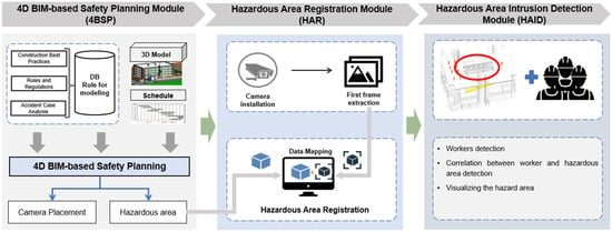
Figure 1.
A 4D BIM- and computer vision-based approach for hazardous area intrusion detection.
3.1. A 4D BIM-Based Safety Planning Module (4BSP)
The development of new tools and methods for safety experts to use motivates these professionals to take the safety of their on-site persons seriously and to build and execute complete safety programs. Hence, more people are becoming aware of the need for a safety plan. Any potential safety risks must be analyzed at each step of the process to ensure that a project is carried out without incident. Moreover, a plan for the tools/equipment used should be prepared for safety monitoring during the construction stage. For instance, the importance of cameras in construction safety management has become increasingly prominent, and practitioners have focused on developing surveillance plans for safety purposes [38].
In this study, the 4D BIM-based safety planning module (4BSP) is used to provide the input information to support the monitoring system. First, rules for modeling are structured based on implicit/explicit safety knowledge. By analyzing accident cases, constructing best practices, management, and regulations, project employees can establish a rationale for generating an automated safe planning system that converges with the fourth-dimensional model. For instance, following OSHA regulation number 1926.451(h) regarding falling-object protection from scaffolding, the space below the scaffold into which things may fall should be walled, and on-site persons must not be allowed to access the hazardous area. The potential hazard area can be visualized in the context of this rule when the scaffolding is being used. According to the literature review of Mei and colleagues [16], the example of rules for defining hazardous areas is shown in Table 3. It points out that the areas 2 m around the scaffold should be considered hazardous. Likewise, other hazard areas may be identified and visualized in 4BSP. Second, the project employee can prepare the plan for installing cameras and equip them at the construction jobsites, as depicted in Figure 2. The module 4D BIM is helpful for defining monitoring regions, considering the dynamic nature of building projects. The schedule divides the construction into phases that follow project milestones, and each phase has a specific site layout plan. Site layouts, which change throughout construction based on the project timetable, affect camera planning alternatives. In this case, the challenge is to accommodate the site layout adjustment that may hinder camera vision. Furthermore, phase layouts (containing details on the building, site amenities, enclosure, storage yard, and equipment) may be used to determine camera placement locations. Installable locations may include semi-permanent or permanent facility boundaries (such as fences, site offices, and tower cranes), whereas non-installable locations include work zones, travel paths, storage yards, and temporary facilities. In addition, surveillance systems are essential for protecting potentially hazardous places from trespassers and maintaining round-the-clock surveillance of them. The construction safety-monitoring system can track potentially hazardous activities.
Table 3.
Rule-based analysis for modeling, according to [16].
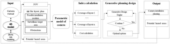
Figure 2.
Generative planning process of surveillance camera systems.
3.2. Hazardous Areas Registration Module (HAR)
By using the information from the 4BSP, the safety manager can determine the input parameters for the second module, called hazardous areas registration (HAR). After defining the position of the camera, the safety managers can extract the virtual view of the camera as a 2D image. If there are m site layouts, the planner would extract m virtual images. Moreover, at planning, the position of control points, which is represented by the yellow components, is planned in the BIM model, as depicted in Figure 3. The on-site persons then have to place these entities which represent control points at the jobsite in accordance with the plan, which is shown in Figure 4. In this study, the authors utilized the fixed-camera system; hence, the corresponding control points need only be placed once before construction. The control points play a pivotal role in the context of mathematical image processing. They serve as anchor coordinates that establish a correspondence between the mosaic of m virtual images and the actual image. By assigning mathematical values to these control points, such as their pixel positions or spatial coordinates, image stitching algorithms can be employed. Through these transformations, the hazardous area within the construction site can be accurately reconstructed, enabling precise spatial analysis and monitoring. The integration of mathematical principles with control points enhances the capability to identify and define hazardous areas within the construction environment. To confirm that the extracted hazardous-area coordinate fits with the live camera images at the jobsite, the actual image has to correspond to the frame of the camera live stream. The corresponding control points are saved to two ( is number of control points) matrices. For instance, the matrix size for the case study is , with seven control points being used for stitching purposes. Aligning is necessary to transform an image (virtual image) to match the viewpoint of the image it is being composited with (actual image). The primary goal is to change the coordinate system into one that produces images that fit the required perspective. An image may be converted through pure translation, pure rotation, or a similarity transform, which involves translation, rotation, and scaling of the picture to be transformed. Projective transformation was employed in this study to align the virtual and actual images.
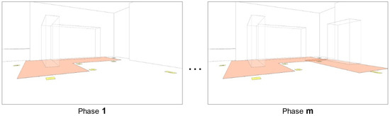
Figure 3.
Control points in the virtual image.
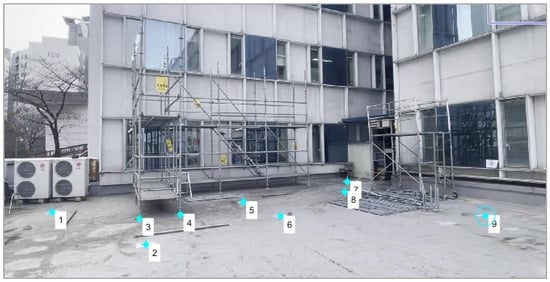
Figure 4.
Control points in the actual image.
A 2-D geometric transformation is a function that maps a set of points in the source coordinate system to a set of points in the target coordinate system. A projective transformation is a particular type of 2-D geometric transformation that maps straight lines to straight lines. The projective transformation can be represented by a matrix H, which maps a homogeneous coordinate to another homogeneous coordinate . The actual Cartesian coordinates can be obtained by dividing the homogeneous coordinates by . Matrix H can be estimated by solving a system of linear equations, where the coefficients of the matrix are obtained from the correspondences between the source and target control points. In this system, each control-point correspondence is represented by a pair of equations:
where are the elements of matrix H.
Given n control point pairs, the system of linear equations can be written as an matrix A:
where are the source control point coordinates, and are the target control-point coordinates.
Matrix H can be obtained by solving the linear system , where is the vector of unknowns and 0 is the zero vector. Solution h can be obtained through a singular value decomposition or other methods. Once the matrix H is estimated, it can be used to transform any point in the source coordinate system to the corresponding point in the target coordinate system by applying the formula . Now that a set of points are obtained, matrix H should be calculated robustly for and the equation must satisfy .
then
3.3. Hazardous Area Intrusion Detection Module (HAID)
Intrusion detection on a construction site refers to the process of identifying unauthorized access or presence on the site. This can be important for a variety of reasons, including preventing the theft of construction materials, protecting against vandalism, and, primarily, ensuring the safety of on-site persons. Computer vision-based object detection can also play a role in intrusion detection in the construction site by automatically identifying the presence of unauthorized individuals in real time. Object detection can be utilized to track the movement of people and vehicles on the construction site and alert security personnel to any suspicious activity. HAID involves computer vision-based on-site person detection and object correlation analysis.
3.3.1. Hazardous-Area Extraction
The process of hazardous-area extraction is illustrated in Figure 5. After combining the actual and virtual images, the hazardous zone from the virtual image can now be used as the actual hazard zone. However, the polygon information of this area is unknown. Thus, the next step is to apply the algorithm for color-based hazardous-area extraction, as presented in Algorithm 1. As seen in the virtual image, the danger zone was represented by orange. Thus, we can extract the parameters of this region based on this color. First, all orange areas were selected, after which the noise areas were removed based on pixel size. Areas with small pixel sizes were discarded, and large pixel sizes were retained based on a defined threshold. The large group of pixels was then consolidated into a single-area format by finding the biggest contour. Every intersection coordinate of the lines was then identified and saved to a matrix as area information. This information was then utilized in the next step to establish a correlation between the person and the hazardous zone.
| Algorithm 1. Algorithm of color-based extraction |
| Input: Register virtual image (image) Output: The contour zone around the hazardous zone and the intersection point (intersection Color) Library: OpenCV 1: Read image 2: Set “lower” and “upper” RGB range to obtain the hazardous by color 3: Obtain the zone by masking and bitwise the mask 4: Define the kernel for dilation task and perform dilate —kernel size (5 × 5) —dilate (image, kernel, iteration = 1) 5: Find the biggest contour of the white pixel; —maxContour = findMax(findContours(image), key = contourArea) 6: Simplify the biggest contour shape —epsilon = thresholdValue * arcLength(maxContour) —finalContour = approxPolyDP(maxContour, epsilon) 7: Find the intersection coordinate of maxContour —for i in range(finalContour.shape [0]—1): drawline((finalContour[i][0]), (finalContour[i + 1][0])) intersectionCoor.append(tuple(approx[i][0])) |
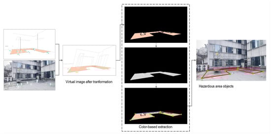
Figure 5.
Hazardous-area objects extraction process.
3.3.2. Computer Vision-Based On-Site Persons Detection
In this study, an on-site person in the hazardous zone is considered an unauthorized object. The Yolov8 model was employed to detect the on-site person at a construction site. Yolov8 was selected due to its processing speed and accuracy being higher than that of other object detection algorithms. Furthermore, Yolov8 excels in detecting small objects. A pre-trained model from the COCO dataset was used to achieve faster convergence, save time, and improve accuracy. The pre-trained model incorporates weights that reflect the learned characteristics of a larger dataset, such as edges and lines. These transferable characteristics are utilized for training a new model on a new dataset. The COCO dataset is a vast collection of images that feature everyday objects [43]. Of these images, 80% were used for training, whereas 20% were used for testing.
3.3.3. Object Correlation Analysis
Yolov8 was utilized to perform object detection; however, achieving automated intruder recognition in a construction site using only Yolov8 predictions is impossible. Therefore, the correlation between the hazardous area and the persons should be determined. In this study, the exact position of the on-site person in the hazardous zone is required. Yolov8 was utilized in this study to detect a person, after which the coordinate of the person was extracted.
The association between the on-site person and the danger zone should be determined to identify incursion occurrence. A person walking into the danger zone is considered an intrusion, and the site administration must be notified. Otherwise, no intrusion occurs if the individual walks close to or outside the danger zone. As shown in Figure 6, the relationship between the on-site person and danger zone is determined by matching specific criteria and the locations of the bounding box of the person and danger zone coordinate. A crucial contribution of this study is the use of overlapping bounding boxes for identifying the correlation between construction elements. The visual intelligence-based correlation detection revealed that the system recognized and masked all humans and danger zones in a given image, as depicted in Figure 6. Figure 6a–d also visually depicts the extraction and comparison of corner coordinates and the y-coordinate of the center in defined bounding boxes. After detection, the system identified and recognized the person class based on the red point; if the red point was inside the hazard zone or on the hazard zone line, the intrusion event was detected, and an alert was sent to the manager; if the red point was outside the hazard zone, the system ignored further processing and declared the scene. In order to evaluate the performance of the intrusion detection model, the authors have used the following metrics—precision, recall, F1-score, and accuracy (Equations (5)–(8)):
where TP, FN, FP, and TN represent the true positive, false negative, false positive, and true negative, respectively. Table 4 presents the definitions of TP, FN, FP, and TN, which are results for intrusion detection in hazardous areas.
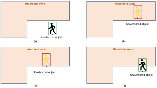
Figure 6.
Correlation analysis.
Table 4.
Definitions of TP, FN, FP, and TN for intrusion in hazardous area.
3.4. Development of Prototype System Based on Proposed Approach
Figure 7 depicts the prototype development process and tool use. The authors used the Autodesk platform for BIM creation and Yolo-V8 for autonomous visual monitoring. Initially, the Primavera timetable was incorporated into the Revit platform to display the 4D BIM environment. The site plans were implemented as follows after the building stages. The authors utilized Revit–Dynamo to conduct a simulation of the site layout, obstacles, and camera field of view. This simulation was performed after the creation of the camera position plan, as illustrated in Figure 2. The authors built control points by using the adaptive component family Revit. The dynamo code was consistently utilized to manipulate the decision variables inside the instructions of the Revit–Dynamo interface and the inherent mathematical algorithms. Afterward, a generative design tool was used to identify a feasible location for the camera system. Figure 8 illustrates the Dynamo code that exported the perspective view of the virtual camera. The authors used the “PerspectiveView.SetFieldofView” node from the Morpheus package to export the virtual image. This image was stitched with an actual image captured from the camera.
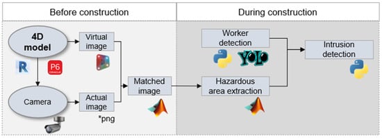
Figure 7.
Process and tool utilization for developing the prototype system.
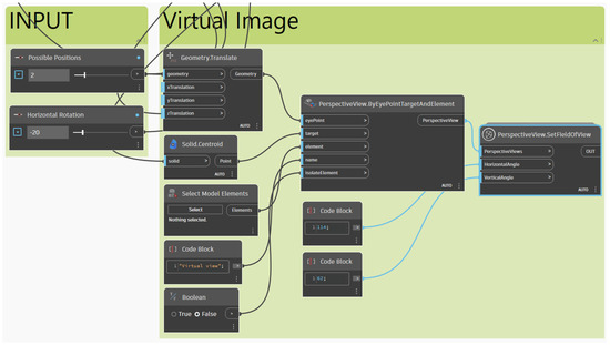
Figure 8.
Process of exporting virtual image.
Dataset Preparation
Both employees and the hazardous area should be detected to monitor hazardous-area entry. After stitching the virtual and actual images, the hazardous area was extracted through image processing using MATLAB R2023a software. Meanwhile, the authors applied the Yolo-V8 algorithms mentioned in Section 3.3 to identify the on-site persons at the construction jobsite. The training was conducted on a server with an i9-10940X CPU, 4x NVIDIA RTX 3090 GPU, and 24 GB RAM. Each minibatch had four images, and the training images were resized to 800 pixels for images with different dimensions. The model was trained at a 0.001 learning rate for 500 epochs, whereas weight decay and learning momentum were set as 0.0001 and 0.9, respectively.
Further, 10,000 additional photos were acquired from various viewpoints at the actual jobsite to train a new model. These photos were collected from an actual site at building 208, Chung-Ang University, as depicted in Figure 9. The dataset was used for private purposes in developing a prototype. In addition, on-site employees who permitted the collection were also required to wear a mask, considering privacy when implementing surveillance techniques on construction sites. After collecting the images, performed data cleaning to obtain an appropriate and useful dataset for training. The input dataset is labeled as an on-site person. After identifying project employees and the hazardous area, the correlation between these objects was calculated. In cases of overlapping, the laborers were considered to have entered the hazardous area.
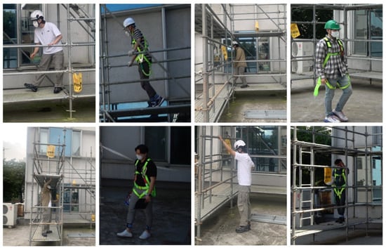
Figure 9.
Some sample images for training.
4. Prototype System Application
4.1. Case Application
The construction site is generally overcrowded, which creates a complex working environment for those employed there. This makes the site managers’ tasks challenging because every on-site construction person has to be manually monitored. Therein, intrusion, defined as the unlawful entry into, or continued to stay in, a dangerous location, is the primary cause of the vast majority of accidents at construction sites. Additionally, most intrusion records are maintained through self-reporting, which is hindered by a blame culture for errors, time-consuming paperwork, and a lack of feedback on how the reported information has been utilized. Consequently, automatically detecting site staff incursions into potentially dangerous regions is a priority for safety monitoring throughout the project’s building phase.
In this study, the authors performed a case study on safety monitoring during a project to repair the facade on the 2nd floor of Building 208 at Chung-Ang University. The on-site people installed scaffolding around the wall. Figure 10 illustrates the plan for placing the scaffolding. At the beginning of the project, a fixed scaffolding system was installed on the left side. After finishing this area, a mobile scaffolding was moved to the right side. OSHA regulation number 1926.451 (h) about falling-object protection during scaffolding requires that the space below the scaffold into which things may fall be walled, and on-site persons must not access the hazardous area. Thus, the hazardous area was visualized in the 4D BIM model. The hazardous area includes 2 m offset from the scaffold. The jobsite is illustrated in Figure 11. The generative planning algorithm for the camera position suggested the optimum location for warning intrusion. Additionally, the authors prepared entities, which are highlighted by red cycles in Figure 12, to support measuring the real dimension of the hazardous area. It was used as the ground truth for comparing the hazardous-area object after transformation.
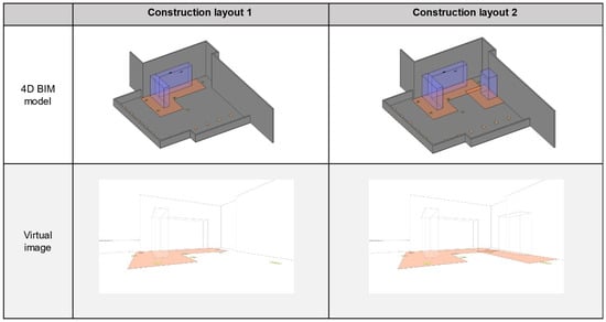
Figure 10.
The Construction site layout.
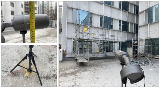
Figure 11.
Photographs of the building 208 jobsite.
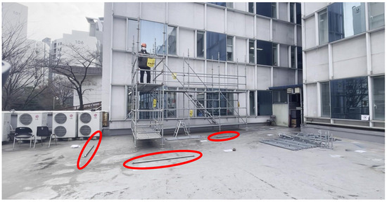
Figure 12.
Hazardous area dimension (ground truth).
4.2. Results
The IDC4D was applied to monitor on-site persons entering hazardous areas during construction. In order to enhance the effectiveness of monitoring, the hazardous areas and on-site persons have to be detected. Therein, hazardous areas need to be considered in the practical situation in the construction job site, such as different geometric, changing from time to time.
The case study was separated into two phases corresponding to two site layouts. Hence, two virtual images extracted from a virtual camera in the 4D BIM model were mosaiced after the actual image, as illustrated in Figure 13. The first-two image is the result of blending the registered virtual image and the actual image (Figure 13a,b). The orange zone of construction layout 1 and construction layout 2 were extracted, and this zone information was drawn again, as represented by the red line on the actual image (Figure 13c,d). These polygons closely fit with the prepared entities, which were used as the ground truth for the 2 m line from scaffolding (Figure 12). These polygons were the hazardous-area objects utilized in the intrusion detection algorithms.
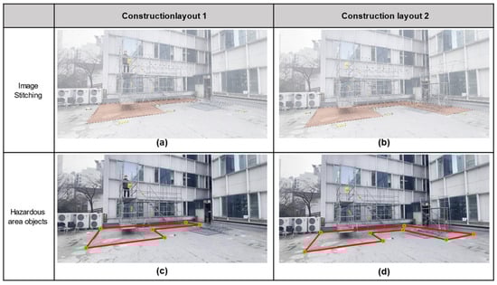
Figure 13.
Extraction of hazardous area objects.
Figure 14 depicts the hazardous-area intrusion detection results. Two scenarios were tested at the project site. The detection model could detect multiple on-site persons in the green bounding box with the label “person” at the construction jobsite. In the case scenarios, two on-site persons were working at the ground level while another was working on the scaffolding. Moreover, the hazardous-area objects of site layouts 1 and 2 were drawn as red polygons following the rules/regulations from the safety plans. In the first scenario, the green-vest on-site person (Figure 14a–d) was working outside the hazardous area; therefore, the employee was represented in a green bounding box and labeled as “person.” Similarly, other on-site persons walking at ground level but not at a dangerous location were visualized by the green bounding box (Figure 14c,d). The second scenario (Figure 14e–h) involved at least one on-site person entering the hazardous area. In phase 1, the warning signal was visualized as a red bounding box, and an “intruder detected” label was assigned when the green-vest on-site person entered the dangerous zone (Figure 14e); the bounding box was then changed to green as the on-site person was moving out of the hazardous area (Figure 14g). In phase 2, the dangerous area was around the mobile scaffolding. Hence, both on-site persons near the fixed and mobile scaffolding were highlighted in red bounding boxes (Figure 14f). As shown in Figure 14g, IDC4D changed the color of the bounding box when the green on-site person was far from the dangerous area. Table 5 presents the performance results of intrusion in hazardous area. The authors recorded videos for each phase for different periods. After conducting the detection, these videos were divided into images per second. After analysis, the algorithm achieved precision, recall and F1-score of 95.3%, 83,7%, 891% for phase 1 and 95.1%, 87,9%, 91.4% for phase 2. Notably, phase 1 and phase 2 yielded an accuracy of 92.5% and 94.1%.
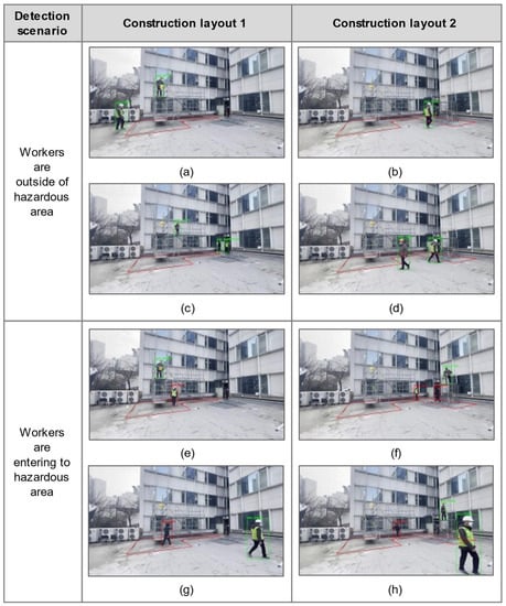
Figure 14.
Detection scenario results.
Table 5.
Performance results of intrusion scenarios.
5. Discussions
This paper proposed an approach to observe intrusion on construction job sites by integrating computer vision and 4D BIM information. In order to enhance the effectiveness of monitoring, the hazardous areas and on-site persons have to be detected. Therein, hazardous areas need to be considered in the practical situation in the construction job site, such as different geometric, changing from time to time. Compared to the past studies related to intrusion monitoring at the construction site, there are three expected contributions to the body of knowledge in the AEC industry.
- Construction sites often contain hazardous areas, and on-site people need to be aware of these areas and take the necessary safety precautions. Common hazardous areas include areas where cranes, forklifts, supply vehicles (especially when driven in the winter), heavy equipment, and hazardous materials are present. Thus, the vision intelligence system needs to have the capability of monitoring multiple types of hazardous-area shapes as stipulated in the relevant laws and regulations. However, previous studies have focused on specific hazardous areas, such as areas around trucks and rectangular openings. In our study, the 3D information on hazardous areas, defined through a rule-based model from the plan, was extracted and transformed to objects for supporting the vision monitoring system. The color-based extraction process was then applied to extract the orange area from registered virtual images. Afterward, the orange-area boundary was extracted as polygons. Accordingly, the hazardous area around the fixed and mobile scaffolds was determined using the intrusion detection algorithm.
- Surveillance camera systems are installed at construction jobsites to monitor potential hazards at specific workspaces. Notably, the hazardous area in the same workspace may change due to shifting to different activities as per the schedule. This study investigated a 4D BIM model that divided the schedule into phases by extracting the hazardous area of each site layout. Accordingly, the hazardous area in the field of view of a virtual camera can be transformed to a suitable object before construction. In the case study, the hazardous areas were defined at phases 1 and 2, which covered the potential hazard area around the scaffolding system, as depicted in Figure 13. In addition, the application of 4D BIM information as a foundation for extracting hazardous-area data assures that the technique may be implemented across projects with diverse scales and levels of intricacy, which may be customized to incorporate the distinctive attributes of the project. The scalability of the project enables the inclusion of developing hazard zones at different phases of development, facilitating their dynamic incorporation. Moreover, a notable characteristic of this technique lies in its capacity to adapt to various sorts of hazardous locations and site layouts. Transferring these hazardous areas as objects into actual images contributes to identifying potential intrusion detection in hazardous areas.
- The IDC4D approach effectively facilitates hazardous-area entry monitoring by establishing a correlation between on-site personnel and designated hazardous zones. This innovative approach leverages 4D Building Information Modeling (BIM) data to extract hazardous area information from virtual environments, subsequently transferring these areas as objects into actual images. Concurrently, on-site person-detection algorithms were developed to identify individuals within the camera’s field of view. Notably, when the identified on-site person objects coincided with the hazardous area objects, an alert was generated and transmitted to safety managers. For instance, Figure 14 illustrated the monitoring results when on-site persons were or were not working near the scaffolding area. In addition, this adaptable approach demonstrates its potential applicability across diverse projects, underlining its versatility in ensuring safety compliance and hazard prevention. Leveraging 4D BIM and camera-based person detection can seamlessly integrate with different project scales, hazardous area types, and site layouts. This versatility positions the approach as a valuable tool for enhancing safety monitoring across various construction endeavors.
Despite this, there are still certain limitations to this study, including the following: (1) This study focused on transforming the hazardous area from the 4D BIM model that would be used as an object in the actual image. However, there are still challenges in this process that on-site persons have to place control points following the plan. With different construction projects and site layouts, safety managers are required to cooperate with planners to develop a safety plan to determine hazardous areas. Furthermore, this study did not analyze the number of control points needed to use for stitching algorithms. (2) In this study, the hazardous areas were highlighted as an orange color; there would be many noise objects if they had the same orange color on the construction job site. (3) The IDC4D technique assumed the 4D BIM level of information. The site layouts that follow the building stages are designed to last for a long time (weeks, months, or years). Therefore, IDC4D may not cover behavior that occurs in brief bursts (hours or days). (4) As shown in Figure 15, misdetections and mistakes occurred during intrusion detection. This was attributable to the on-site person detection model. The data for identifying the on-site person were gathered from a single construction site. To handle the dynamics of the changing environment, the dataset needs to be collected from diverse construction sites. In addition, it should be acquired from different locations, including varying perspectives, occlusion scenarios, and specularities.
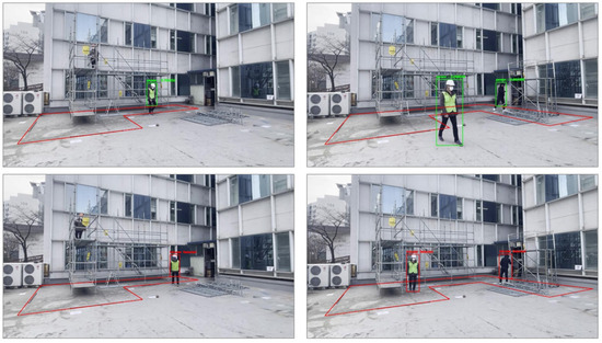
Figure 15.
Errors in the intrusion-detection algorithm.
Moreover, privacy and data usage are the most significant ethical considerations when using surveillance on construction sites. The continual monitoring by cameras raises fears of on-site invasion. Thus, there is a need to balance safety and privacy to ethically implement monitoring systems at construction sites. (1) Informed consent: Inform workers about surveillance cameras, their function, and the regions under observation before installing them. Give workers an explicit agreement to understand and accept monitoring. (2) Transparency: Establish transparent communication channels regarding the camera system. Inform workers about the nature of data nature, storage length, and footage access. This transparency builds confidence and informs workers of their rights. (3) Data anonymization: Implement measures to ensure that the recorded data do not reveal individual identities unless necessary. Use anonymization to preserve workers’ privacy while gaining safety insights. (4) Data security and storage: Protect captured footage using rigorous data security methods. Prevent data retention by setting storage and deletion limits. (5) Regular review and assessment: Evaluate the camera system’s safety benefits. Regularly discuss worker problems and make modifications based on their comments. (6) Legal Compliance: Follow local data privacy and surveillance rules while installing surveillance cameras. Adhering to legal frameworks provides a foundation for ethical practices.
6. Conclusions
This research has presented the IDC4D approach that supports safety monitoring by enhancing intrusion detection in hazardous areas at the construction job site. The study’s primary goal was to extract the hazardous area from the 4D BIM model as the objects that would be used for determining the relationship between them and on-site persons. Through this, the safety warning was delivered in case of overlapping between on-site person objects and hazardous area objects. A thorough literature review indicated a need for developing an approach to monitor the hazardous area entry cases considering the multiple workspace shape and dynamic nature of the construction job site. Furthermore, the suggested hybrid monitoring system, which incorporates 4D BIM information and computer vision technologies, may significantly assist safety managers in identifying intrusion during construction.
The IDC4D comprises three modules: (1) 4BSP, which analyzes the hazardous area; (2) HAR, which transfers the hazardous area information from the BIM model to the first frame image of the camera; and (3) HAID, which applies a computer vision algorithm to identify the correlation between on-site persons and the hazardous area. Autodesk Revit-Dynamo was utilized for establishing an appropriate surveillance plan. Afterward, the virtual view of the camera was exported as a virtual image (for specific site layouts). The hazardous-area extraction process can be applied to extracting hazardous-area objects during construction. The on-site person detection model was also trained using Yolo-V8. The correlation between hazardous area objects and on-site persons was leveraged to deliver the warning signal. The findings of the study indicate that the IDC4D approach exhibits promise in improving intrusion monitoring at construction sites through three fundamental mechanisms: (1) proficiently extracting various forms of workspace configurations, (2) accounting for the dynamic nature of the environment by adapting to changes in the hazardous area during different activities, and (3) offering a safety signal by analyzing the proximity between individuals present on-site and the hazardous area. For future research, the following aspects should be considered: (1) analysis of safety rules/regulations and incorporating contextual information that supports the 4BSP module to find the geometry of the hazardous area. (2) The on-site person’s identity should be integrated into the detection algorithm, for instance applying biometric computing for face recognition and registration [44], to analyze their routine/reflex aimed to support monitoring and education. However, individuals have to be informed of the presence of surveillance, the reason for data collection, and their rights regarding the management of their personal information. (3) A larger dataset should be utilized to improve the detection algorithms. An (4) exploring method of feedbacks after intrusion detection should be used and safety status should be delivered to other stakeholders.
Author Contributions
Conceptualization, S.V.-T.T. and D.L.; data curation, S.V.-T.T. and Q.L.B.; methodology, S.V.-T.T. and M.K.; supervision, C.P.; writing—original draft, S.V.-T.T., T.Y. and J.J.; writing—review and editing, S.V.-T.T. and C.P. All authors have read and agreed to the published version of the manuscript.
Funding
This research was supported by the National Research Foundation of Korea (NRF) grant funded by the Korea government (MSIT) (No. NRF-2022R1A2B5B02002553). This research was conducted with the support of the “National R&D Project for Smart Construction Technology (No.22SMIP-A158708-04)” funded by the Korea Agency for Infrastructure Technology Advancement under the Ministry of Land, Infrastructure and Transport, and managed by the Korea Expressway Corporation.
Data Availability Statement
The data that support the findings of this study are available from the corresponding author upon reasonable request.
Acknowledgments
This research was supported by the Chung-Ang University Research Scholarship Grants in 2022.
Conflicts of Interest
The authors declare no conflict of interest.
References
- Zhang, M.; Shi, R.; Yang, Z. A critical review of vision-based occupational health and safety monitoring of construction site workers. Saf. Sci. 2020, 126, 104658. [Google Scholar] [CrossRef]
- Fang, W.; Ding, L.; Love, P.E.D.; Luo, H.; Li, H.; Peña-Mora, F.; Zhong, B.; Zhou, C. Computer vision applications in construction safety assurance. Automat. Constr. 2020, 110, 103013. [Google Scholar] [CrossRef]
- OSHA Fatality Report. Available online: https://www.osha.gov/stop-falls (accessed on 6 October 2022).
- Construction Work|Statistics Korea. Available online: http://kostat.go.kr/portal/eng/pressReleases/4/5/index.board (accessed on 6 October 2022).
- Accidents at Work Statistics—Statistics Explained. Available online: https://ec.europa.eu/eurostat/statistics-explained/index.php?title=Accidents_at_work_statistics#Number_of_accidents (accessed on 2 February 2023).
- Tran, S.V.T.; Khan, N.; Lee, D.; Park, C. A Hazard Identification Approach of Integrating 4D BIM and Accident Case Analysis of Spatial–Temporal Exposure. Sustainability 2021, 13, 2211. [Google Scholar] [CrossRef]
- Luo, X.; Li, H.; Wang, H.; Wu, Z.; Dai, F.; Cao, D. Vision-based detection and visualization of dynamic workspaces. Automat. Constr. 2019, 104, 1–13. [Google Scholar] [CrossRef]
- Bao, L.; Tran, S.V.T.; Nguyen, T.L.; Pham, H.C.; Lee, D.; Park, C. Cross-platform virtual reality for real-time construction safety training using immersive web and industry foundation classes. Automat. Constr. 2022, 143, 104565. [Google Scholar] [CrossRef]
- Chen, H.; Li, H.; Goh, Y.M. A review of construction safety climate: Definitions, factors, relationship with safety behavior and research agenda. Saf. Sci. 2021, 142, 105391. [Google Scholar] [CrossRef]
- Jin, R.; Zhang, H.; Liu, D.; Yan, X. IoT-based detecting, locating and alarming of unauthorized intrusion on construction sites. Automat. Constr. 2020, 118, 103278. [Google Scholar] [CrossRef]
- Park, J.; Asce, S.M.; Marks, E.; Cho, Y.K.; Suryanto, W. Performance Test of Wireless Technologies for Personnel and Equipment Proximity Sensing in Work Zones. J. Constr. Eng. Manag. 2015, 142, 04015049. [Google Scholar] [CrossRef]
- Fang, W.; Zhong, B.; Zhao, N.; Love, P.E.D.; Luo, H.; Xue, J.; Xu, S. A deep learning-based approach for mitigating falls from height with computer vision: Convolutional neural network. Adv. Eng. Inform. 2019, 39, 170–177. [Google Scholar] [CrossRef]
- Khan, M.; Khalid, R.; Anjum, S.; Tran, S.V.-T.; Park, C. Fall Prevention from Scaffolding Using Computer Vision and IoT-Based Monitoring. J. Constr. Eng. Manag. 2022, 148, 04022051. [Google Scholar] [CrossRef]
- Yang, J.; Lee, D.; Baek, C.; Park, C.; Lan, B.Q.; Lee, D. Leveraging Blockchain for Scaffolding Work Management in Construction. IEEE Access 2022, 10, 39220–39238. [Google Scholar] [CrossRef]
- Kim, H.; Lee, H.S.; Park, M.; Chung, B.Y.; Hwang, S. Automated hazardous area identification using laborers’ actual and optimal routes. Automat. Constr. 2016, 65, 21–32. [Google Scholar] [CrossRef]
- Mei, X.; Zhou, X.; Xu, F.; Zhang, Z. Human Intrusion Detection in Static Hazardous Areas at Construction Sites: Deep Learning–Based Method. J. Constr. Eng. Manag. 2023, 149, 04022142. [Google Scholar] [CrossRef]
- Akram, R.; Thaheem, M.J.; Nasir, A.R.; Ali, T.H.; Khan, S. Exploring the role of building information modeling in construction safety through science mapping. Saf. Sci. 2019, 120, 456–470. [Google Scholar] [CrossRef]
- Alizadehsalehi, S.; Yitmen, I.; Celik, T.; Arditi, D. The effectiveness of an integrated BIM/UAV model in managing safety on construction sites. Int. J. Occup. Saf. Ergon. 2018, 26, 829–844. [Google Scholar] [CrossRef] [PubMed]
- Khan, M.; Nnaji, C.; Khan, M.S.; Ibrahim, A.; Lee, D.; Park, C. Risk factors and emerging technologies for preventing falls from heights at construction sites. Autom. Constr. 2023, 153, 104955. [Google Scholar] [CrossRef]
- Huang, M.Q.; Ninić, J.; Zhang, Q.B. BIM, machine learning and computer vision techniques in underground construction: Current status and future perspectives. Tunn. Undergr. Space Technol. 2021, 108, 103677. [Google Scholar] [CrossRef]
- Xu, W.; Wang, T.K. Dynamic safety prewarning mechanism of human–machine–environment using computer vision. Eng. Constr. Archit. Manag. 2020, 27, 1813–1833. [Google Scholar] [CrossRef]
- Yang, B.; Zhang, B.; Zhang, Q.; Wang, Z.; Dong, M.; Fang, T. Automatic detection of falling hazard from surveillance videos based on computer vision and building information modeling. Struct. Infrastruct. Eng. 2022, 18, 1049–1063. [Google Scholar] [CrossRef]
- Tang, S.; Shelden, D.R.; Eastman, C.M.; Pishdad-Bozorgi, P.; Gao, X. A review of building information modeling (BIM) and the internet of things (IoT) devices integration: Present status and future trends. Automat. Constr. 2019, 101, 127–139. [Google Scholar] [CrossRef]
- Tran, S.V.; Bao, L.Q.; Nguyen, L.T.; Pedro, A. Development of Computer Vision and BIM-cloud based Automated Status Updating for Construction Safety Monitoring. In Proceedings of the 22nd International Conference on Construction Applications of Virtual Reality (CONVR2022), Seoul, Republic of Korea, 16–19 November 2022. [Google Scholar]
- Winsemius, W. Some ergonomic aspects of safety. Ergonomics 2007, 8, 151–162. [Google Scholar] [CrossRef]
- CPWR|Practice Trench Safety. It Saves Lives. Available online: https://www.cpwr.com/practice-trench-safety-it-saves-lives/ (accessed on 8 December 2022).
- Hinze, J.; Godfrey, R. An evaluation of safety performance measures for construction projects. J. Constr. Res. 2003, 04, 5–15. [Google Scholar] [CrossRef]
- Xu, Q.; Chong, H.Y.; Liao, P.C. Collaborative information integration for construction safety monitoring. Automat. Constr. 2019, 102, 120–134. [Google Scholar] [CrossRef]
- Kanan, R.; Elhassan, O.; Bensalem, R. An IoT-based autonomous system for workers’ safety in construction sites with real-time alarming, monitoring, and positioning strategies. Automat. Constr. 2018, 88, 73–86. [Google Scholar] [CrossRef]
- Shuang, D.; Heng, L.; Skitmore, M.; Qin, Y. An experimental study of intrusion behaviors on construction sites: The role of age and gender. Saf. Sci. 2019, 115, 425–434. [Google Scholar] [CrossRef]
- Huang, H.; Hu, H.; Xu, F.; Zhang, Z.; Tao, Y. Skeleton-based automatic assessment and prediction of intrusion risk in construction hazardous areas. Saf. Sci. 2023, 164, 106150. [Google Scholar] [CrossRef]
- Wan, H.-P.; Zhang, W.-J.; Ge, H.-B.; Luo, Y.; Todd, M.D. Improved Vision-Based Method for Detection of Unauthorized Intrusion by Construction Sites Workers. J. Constr. Eng. Manag. 2023, 149, 04023040. [Google Scholar] [CrossRef]
- Kim, D.; Liu, M.; Lee, S.H.; Kamat, V.R. Remote proximity monitoring between mobile construction resources using camera-mounted UAVs. Automat. Constr. 2019, 99, 168–182. [Google Scholar] [CrossRef]
- Hua, Y.; He, J.; Gong, J.; Zhao, J. Hazardous Area Risk-Based Evacuation Simulation and Analysis of Building Construction Sites. J. Constr. Eng. Manag. 2020, 146, 5. [Google Scholar] [CrossRef]
- Tran, S.; Ali, A.K.; Khan, N.; Lee, D.; Park, C. A Framework for Camera Planning in Construction Site using 4D BIM and VPL. In Proceedings of the 37th International Symposium on Automation and Robotics in Construction (ISARC), Kitakyushu, Japan, 27–28 October 2020. [Google Scholar]
- Feng, C.-W.; Lu, S.-W. Using BIM to Automate Scaffolding Planning for Risk Analysis at Construction Sites. In Proceedings of the 34th International Symposium on Automation and Robotics in Construction, ISARC 2017, Taipei, Taiwan, 28 June–July 2017; International Association for Automation and Robotics in Construction: Edinburgh, UK, 2017; pp. 610–617. [Google Scholar]
- Getuli, V.; Capone, P.; Bruttini, A.; Isaac, S. BIM-based immersive Virtual Reality for construction workspace planning: A safety-oriented approach. Automat. Constr. 2020, 114, 103160. [Google Scholar] [CrossRef]
- Tran, S.V.T.; Nguyen, T.L.; Chi, H.L.; Lee, D.; Park, C. Generative planning for construction safety surveillance camera installation in 4D BIM environment. Automat. Constr. 2022, 134, 104103. [Google Scholar] [CrossRef]
- Arslan, M.; Cruz, C.; Ginhac, D. Visualizing intrusions in dynamic building environments for worker safety. Saf. Sci. 2019, 120, 428–446. [Google Scholar] [CrossRef]
- Valinejadshoubi, M.; Moselhi, O.; Bagchi, A.; Salem, A. Development of an IoT and BIM-based automated alert system for thermal comfort monitoring in buildings. Sustain. Cities Soc. 2021, 66, 102602. [Google Scholar] [CrossRef]
- Zhou, X.; Li, H.; Wang, J.; Zhao, J.; Xie, Q.; Li, L.; Liu, J.; Yu, J. CloudFAS: Cloud-based building fire alarm system using Building Information Modelling. J. Build. Eng. 2022, 53, 104571. [Google Scholar] [CrossRef]
- Tran, S.V.T.; Nguyen, T.L.; Park, C. A BIM Integrated Hazardous Zone Registration Using Image Stitching. In Proceedings of the 38th International Symposium on Automation and Robotics in Construction, Dubai, United Arab Emirates, 2–4 November 2021; pp. 176–181. [Google Scholar] [CrossRef]
- Lin, T.Y.; Maire, M.; Belongie, S.; Hays, J.; Perona, P.; Ramanan, D.; Dollár, P.; Zitnick, C.L. Microsoft COCO: Common objects in context. In Lecture Notes in Computer Science; Springer: Berlin/Heidelberg, Germany, 2014; pp. 740–755. [Google Scholar] [CrossRef]
- Arya, K.V.; Bhadoria, R.S. The Biometric Computing: Recognition and Registration; CRC Press: Boca Raton, FL, USA, 2019; ISBN 1351013424. [Google Scholar]
Disclaimer/Publisher’s Note: The statements, opinions and data contained in all publications are solely those of the individual author(s) and contributor(s) and not of MDPI and/or the editor(s). MDPI and/or the editor(s) disclaim responsibility for any injury to people or property resulting from any ideas, methods, instructions or products referred to in the content. |
© 2023 by the authors. Licensee MDPI, Basel, Switzerland. This article is an open access article distributed under the terms and conditions of the Creative Commons Attribution (CC BY) license (https://creativecommons.org/licenses/by/4.0/).