Article

Mechanical Model and Damping Effect of a Particle-Inertial Damper

1
Faculty of Architecture, Civil and Transportation Engineering, Beijing University of Technology, Beijing 100021, China
2
School of Water Resources and Hydropower Engineering, North China Electric Power University, Beijing 102206, China
3
China Railway Construction Group Co., Ltd., Beijing 100040, China
4
School of Civil Engineering, Shijiazhuang Tiedao University, Shijiazhuang 050043, China
*
Author to whom correspondence should be addressed.
These authors contributed equally to this work.
Buildings 2023, 13(9), 2264; https://doi.org/10.3390/buildings13092264
Submission received: 2 August 2023 / Revised: 27 August 2023 / Accepted: 4 September 2023 / Published: 6 September 2023
(This article belongs to the Special Issue Structural Vibration Control Research)

Abstract

:
Particle dampers (PD) are safe, economical, and effective energy-dissipation devices for structures. However, the additional mass of PD must be sufficiently large to provide a better damping effect, and the initial movement condition of particles has a significant impact on the damping effect of PD. In this study, a particle-inertial damper (PID) is proposed to overcome these problems, and its mechanical model is established with and without considering particle collision. Subsequently, the influence of particle rolling friction and particle collision on the inertial amplification capacity as well as the dynamic response of a single degree of freedom (SDOF) structure with non-collision and collision PID (SDOF-PID) are systematically analysed. Finally, the control effects of a PID and a tuned mass damper (TMD) are compared based on two typical optimisation methods. The results indicate that particle rolling friction has little influence on the inertia amplification effect of a PID and the displacement response of a SDOF-PID. Under harmonic excitation, particle collision significantly affects the damping mechanism of a PID by its equivalent inertia coefficient, equivalent damping coefficient, and equivalent stiffness coefficient. The fixed-point theory and ‘performance-cost’ theory can be used to optimise the PID to a certain extent. The damping effect of a PID on the SDOF under the most severe seismic excitation is better than that of the PID under white noise excitation. With respect to the decreasing ratio of 40~50%, the additional mass of the PID is only one thousandth that of the TMD under the same damping capacity demand.

1. Introduction

A particle damper (PD) is an energy-dissipating equipment that places particles into a cavity container at a certain filling rate [1,2]; in other words, the PD can consume the kinetic energy of the controlled structure through friction and collisions between particles or between particle and cavity wall [3]. The PDs have advantages of a flexible arrangement, wide frequency band of vibration reduction, strong robustness, low cost, etc. Further, PDs can be divided into single-particle dampers (S-PDs) [4] and multi-particle dampers (M-PDs) [5].
The S-PD was developed from an impact damper [6]. Grubin [7] established a theoretical analysis model of S-PD by introducing a collision recovery coefficient and assuming that the collision between the particle and cavity wall was an inelastic collision. Masri [8,9] deduced the steady state vibration equation of S-PD under periodic excitation. Saeki [10] determined the optimal motion spacing of an S-PD particle under harmonic excitations. Yan [11] considered the influence of friction between particles and controlled structures on the damping performance of S-PDs and pointed out that the influence of friction should not be ignored under low-frequency and low-amplitude excitation. Yan [12] established a mechanical model of a parallel single-dimensional S-PD (PS-S-PD) and proposed a parameter optimisation analysis method for PS-S-PD. Lu [13] proposed a multiple tuned impact damper (MTID) by combining S-PD and multiple tuned mass dampers, and they indicated that the MTID can significantly reduce the plasticity and damage of the structure under large earthquakes. Muhammad [14] proposed a hybrid damper by combining a particle impact damper and a Coulomb friction damper. The proposed damper is found to be effective over a wide range of excitation frequencies and achieves a similar vibration suppression performance to the traditional tuned mass damper (TMD) of a similar mass ratio.
S-PDs produce a large amount of noise and have poor robustness because of single-particle collisions. Therefore, M-PDs have received increasing research attention. For example, Masri [15] analysed the effects of the mass ratio, excitation level, and other parameters on the energy dissipation characteristics of M-PDs through shaking table tests. Friend [16] obtained the ‘effective coefficient of recovery’ to evaluate the damping effect of an M-PD arranged in a cantilever beam. Saeki [17] studied the parameter influence law on the damping effect of M-PDs under horizontal harmonic excitation through a test and discrete element method; they pointed out that the damping effect of M-PD is significantly affected by the particle mass and size. Further, Pendleton [18] reported that the M-PD has a good damping effect over a wide frequency range (1–500 Hz). Wang [19] verified the damping effect of M-PDs at different frequencies (20–2000 Hz). Lu [20,21] elucidated the damping effect and parameter influence law of the M-PD by experiment and numerical simulation.; this can be referenced with the application of the M-PD. In addition, Yan [22,23] verified the damping effect of M-PDs on the seismic response of a continuous girder bridge and a three-story frame through shaking table tests. Lu [24] establishes a mechanical model of the particle damper for tremor suppression, and the particle damper effectiveness in reducing tremor is validated by numerical simulations and experimental studies. Lu [25] established the discrete element model of the particle damper, and the energy dissipation mechanism and characteristics of the particle damper were further explored based on the time-history responses of the contact force and energy dissipation.
Recent findings indicate that the M-PD has complex nonlinear characteristics, and the damping mechanism of the M-PD needs to be revealed by theoretical analysis. Papalou [26] modelled an M-PD as an S-PD using the principle of the same volume and mass; further, they verified the rationality of the model using experimental results. Lu [27] established an equivalent mechanical model of PTMD using an equivalent single-particle model and the contact element method. Subsequently, the rationality of the equivalent mechanical model of the PTMD is verified through a structural response test under an earthquake. Huang [28] created an M-PD equivalent to the dual-mass equivalent model (DMEM) and verified the effectiveness of the DMEM through testing. Xu [29] simplified the particle tuned mass damper (PTMD, a type of M-PD) to a double-tuned mass damper (DTMD) and verified the effectiveness of the DTMD model through testing. By introducing inertia, Xu [30,31] considers the effect of particle rolling on M-PD damping effect and establishes the equivalent inertial single particle model (EISM). Subsequently, the EISM model was proven to reflect the frictional rolling mechanism of the M-PD. Recent findings indicate that the damping effects of the traditional S-PD and M-PD cannot be stable because of their complex nonlinear characteristics [32,33,34]. The application of S-PDs and M-PDs is considerably limited because of the high initial movement condition of particles, larger additional mass, and significant installation space, especially in civil engineering.
Based on the above mentioned points, a particle-inertial damper (PID) was proposed, which can first significantly reduce the vibration condition of particles, additional mass, and installation space requirements of traditional PD. Subsequently, a mechanical model of the PID with and without particle collisions is established. The influence of particle rolling friction and particle collision on the inertial amplification capacity as well as the dynamic response of a single degree of freedom (SDOF) with a non-collision and collision PID are systematically analysed. Finally, the damping effects of the PID and TMD are compared based on two typical optimisation methods. The findings can be used as a reference to improve the damping behaviour and application scenarios of PDs.

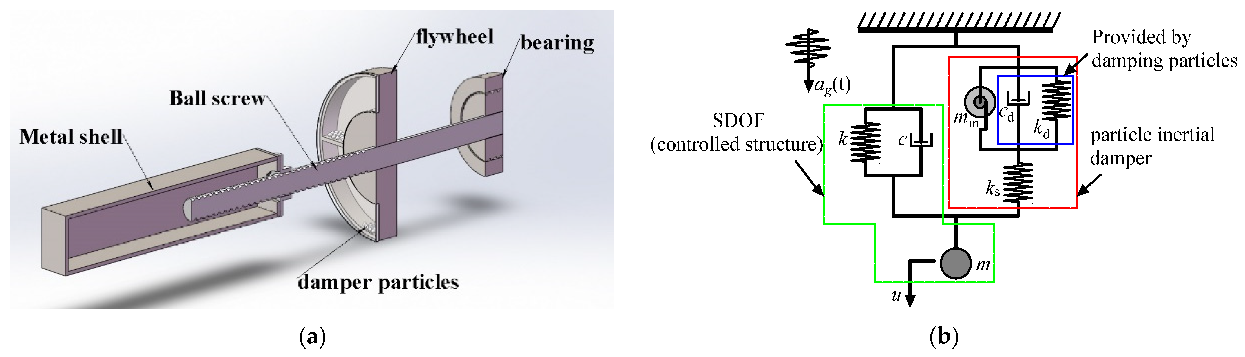
2. Mechanical Model of the PID

Current research shows that the tuning and energy dissipation capacity of particle dampers (PDs) are affected by the particle motion state. When there is no relative motion between the particle and the controlled structure, the tuning and energy dissipation capacity of PDs are limited. To solve this problem, we proposed a particle-inertial damper (PID).
A PID consists of a flywheel, particles, ball screw and metal shell, as shown in Figure 1a. When there are no particles in the flywheel. The PID can be regarded as a kind of inertial damper (ID). For an ID, it can tune and absorb the kinetic energy of a controlled structure. However, the absorbed kinetic energy will also transfer to the controlled structure when there are no effective energy consumption methods. To provide an effective energy consumption mechanism for an ID, the PID was proposed. The particles can make relative movement and collide with the cavity of the flywheel. Therefore, the friction and collision between particles as well as particles and flywheel will dissipate the absorbed kinetic energy. The particles can not only provide inertia mass of the flywheel, but also a damping effect without impacting the inertia effect of the ID. Accordingly, a PID is more practical.
Based on the aforementioned discussion, the inertial element (flywheel) and stiffness element (ball screw) of a PID provided inertial coefficient (min) and effective stiffness (ks). The particles of a PID provided additional damping (cd) and additional stiffness (kd) when the particles collide with the flywheel. Accordingly, the mechanical model of a PID is shown in Figure 1b within the red box. A SDOF only has three separate parameters, mass (m), stiffness (k), and damping (c). A SDOF is widely used to optimize the design parameters of a damper [29,30,31]. In this study, the controlled structure was also simplified as a SDOF (shown in Figure 1b within the green box), and a SDOF-PID system is shown in Figure 1b; ag(t) was the acceleration input of the controlled structure.
To establish the mechanical model of the PID, the following assumptions were made: (1) the PID was placed vertically and the particles move horizontally in the cavity of the flywheel; (2) the collision between the particle and the cavity of the flywheel was continuous positive collision. As Figure 1b presented, the dynamic equation of a PID can be expressed as follows:
F I S = k s ( u x d ) m i n x ¨ d + c d x ˙ d + k d x d = F I S
where FIS represents the output of PID; ks represents the effective stiffness of PID; min, cd, and kd represent inertia coefficient, equivalent damping coefficient, and equivalent stiffness coefficient of PID; u represents the displacement of controlled structure; and xd represents the relative displacement of both ends of the PID.

2.1. Without Particle Collision

If the particle did not collide with the flywheel wall, the PID dissipated and tuned the energy of the controlled structure through the rolling friction between the particle and flywheel wall as well as the rolling of the flywheel. When the particles had relatively stable movement with the flywheel, the direction of friction force on the flywheel changed constantly. When the direction of the friction force of the particles as well as the additional torque provided by the particles was the same with that of the inertia force of the flywheel, the damping force of the PID was the sum of the friction force and the inertia force. On the contrary, when the direction of the friction force of the particles was opposite with that of the inertia force of the flywheel, the damping force of the PID was the difference between them. Therefore, the torque balance equation of the PID and dynamic equation of the particle are given as:
T = J S α S ± F s r i m i x ¨ i = F s ,
where T, Js, αs, mi, xi, r i , and Fs represent the driving torque of the ball screw, polar moment of inertia of the flywheel (as shown in Equation (3)), angular acceleration of the flywheel, particle mass, particle displacement, distance between the particle and flywheel axis, and the force required by the particle to overcome its rolling friction torque (moment) (as shown in Equation (4)).
J s = 1 2 ( r 0 2 + r 2 ) m 0 ,
where r0m0, r represents the radius of ball screw, the mass of flywheel, and the radius of flywheel, respectively.
F s = 1 r i μ f m i g ,
where μ f and ri represent the rolling friction coefficient and radius of particle, respectively; g is acceleration of gravity. Moreover, ball screw can convert rotational motion into linear operation [35]. Therefore, we have:
ω = 2 π P x ˙ d F I S = 2 π P T α s = 2 π P x ¨ d ,
where P, ω represents the lead and rotation angular velocity of the ball screw, respectively. Taking into consideration Equations (2)~(5), the output of PID is shown in Equation (6):
F I S = 2 π 2 ( r 0 2 + r 2 ) P 2 m 0 x ¨ d ± 2 π r i r i P μ f m i g ,
Equation (6) shows that the damping coefficient and stiffness coefficient of the damping particle are both zero when the particle does not collide with the flywheel wall. Equation (6) can be simplified to:
F I S = m i n x ¨ d ± m i 0 g ,
where min and mi0 represent the flywheel equivalent inertia coefficient and particle equivalent inertia coefficient, which are the coefficient terms of Equation (6), respectively. We assumed mi = βm0 to study the effect of friction on the equivalent inertia coefficient of the flywheel. β ranges from 0 to 1 because the particles provide a certain filling rate in the flywheel cavity. The ratio of the equivalent inertia coefficients of the flywheel and particle to the flywheel mass is given by:
μ 1 = m i n m 0 = 2 π 2 r 0 2 ( 1 + φ 2 ) P 2 μ 2 = m i 0 m 0 = β μ f 2 π r i r i P ,
where φ   =   r / r 0 . As shown in Equation (8), the equivalent inertia coefficient was closely related to the lead of the ball screw. The relationship between the mass ratio and screw lead is illustrated in Figure 2 and Figure 3.
Figure 2 and Figure 3 show that the mass ratio decreases with increasing lead. The smaller the lead, the larger the inertial mass of the flywheel was. However, a decrease in lead reduced the lifetime and transmission efficiency of the damper. Under the same lead, a larger ratio of the radius of the flywheel to the ball screw φ as well as the particle rolling friction coefficient μf resulted in a larger particle equivalent inertia coefficient. Moreover, the equivalent inertia coefficient of the particle was more significantly affected by φ and μf when lead was small. Taking into consideration Equations (1) and (7) and Figure 1b, the dynamic equation of SDOF-PID without particle collision is given by Equation (9):
m u ¨ + c u ˙ + k u + F I S = p ( t ) F I S = k s ( u x d ) m i n x ¨ d ± m i 0 g = k s ( u x d ) ,
where m, c, k, and p(t) represent the mass, damping, and stiffness coefficients of the SDOF structure and external incentive, respectively.
To study the influence of particle rolling friction on the displacement response of the SDOF, p(t) = −mag(t); then:
m u ¨ ( t ) + c u ˙ ( t ) + k u ( t ) + k s [ u ( t ) x d ( t ) ] = m a g t m i n x ¨ d ( t ) ± m i 0 g k s [ u ( t ) x d ( t ) ] = 0 ,
where ag(t) is the acceleration input of the controlled structure. Then, Equation (10) is rewritten in a dimensionless form as:
u ¨ ( t ) + 2 ξ 1 ω u ˙ ( t ) + ω 2 u ( t ) + δ 1 ω 2 [ u ( t ) x d ( t ) ] = a g t μ x ¨ d ( t ) ± μ 3 g δ 1 ω 2 [ u ( t ) x d ( t ) ] = 0 ,
where ω = k m , ω s = k s m , ξ 1 = c 2 m ω , μ = m i n m , μ 3 = m i 0 m   and   δ 1 = k s k = ω s 2 ω 2 .
Through the Laplace transform, Equation (11) can be expressed as:
U ( s ) = ( s 2 μ + δ 1 ω 2 ) M ( s , μ , ξ 1 , δ 1 , ω ) A g ( s ) + μ 1 δ 1 ω 2 s M ( s , μ , ξ 1 , δ 1 , ω ) G ,
where M ( s , μ , ξ 1 , δ 1 , ω ) = s 4 μ + 2 s 3 ξ 1 μ ω + s 2 ( δ 1 + μ + δ 1 μ ) ω 2 + 2 s δ 1 ξ 1 ω 3 + δ 1 ω 4 .
Equation (12) indicates that the displacement response of the SODF was composed of two parts: one caused by external excitation and the other caused by the rolling friction of the particle. Thus, it was assumed that the displacement response caused by the external excitation was U1 and that by particle rolling, friction was U2. The displacement transfers function modulus of Equation (12) is given as:
H U 1 ( i α ω ) = 1 ω 2 α 2 μ δ 1 α 4 μ α 2 ( δ 1 + μ + δ 1 μ ) + δ 2 + 4 ( ξ 1 δ 1 α ξ 1 μ α 3 ) 2 H U 2 ( i α ω ) = 1 ω 3 μ 3 δ 1 α 5 μ α 3 ( δ 1 + μ + δ 1 μ ) + δ α 2 + 4 ( ξ 1 μ α 4 ξ 1 δ 1 α 2 ) 2 ,
where α = ω 0 ω and ω0 represents the frequency of the input excitation.
When the basic parameters of the PID were determined, the displacement transfer function curve of the SDOF-PID was obtained by taking into consideration Equations (12) and (13), as shown in Figure 4.
Figure 4 shows that the mass ratio had a significant influence on the amplification effect of the PID. After the PID arrangement, the dynamic amplification coefficient of the SDOF structure changed from a single peak to a double peak. Further, the double peak was separately distributed on the left and right sides of the natural vibration frequency of the SDOF. The response of the PID to the high-frequency excitation showed an obvious inhibitory effect; the response of PID to the low-frequency excitation showed an amplifying effect. Further, the larger the mass ratio between the flywheel and SDOF, the wider the effective suppression frequency band of the PID was. Combined with Equation (8), the equivalent inertial coefficients of the flywheel and particle were also determined when the basic parameters of the PID were determined. Therefore, the displacement response U1 caused by external excitation was considerably larger than the displacement response U2 caused by the particle rolling friction under the same conditions. In other words, the rolling friction of the particle had little influence on the inertia amplification effect of the flywheel. Without particle collision, the inertia mechanism of the PID damper was similar to that of the inertial damper.

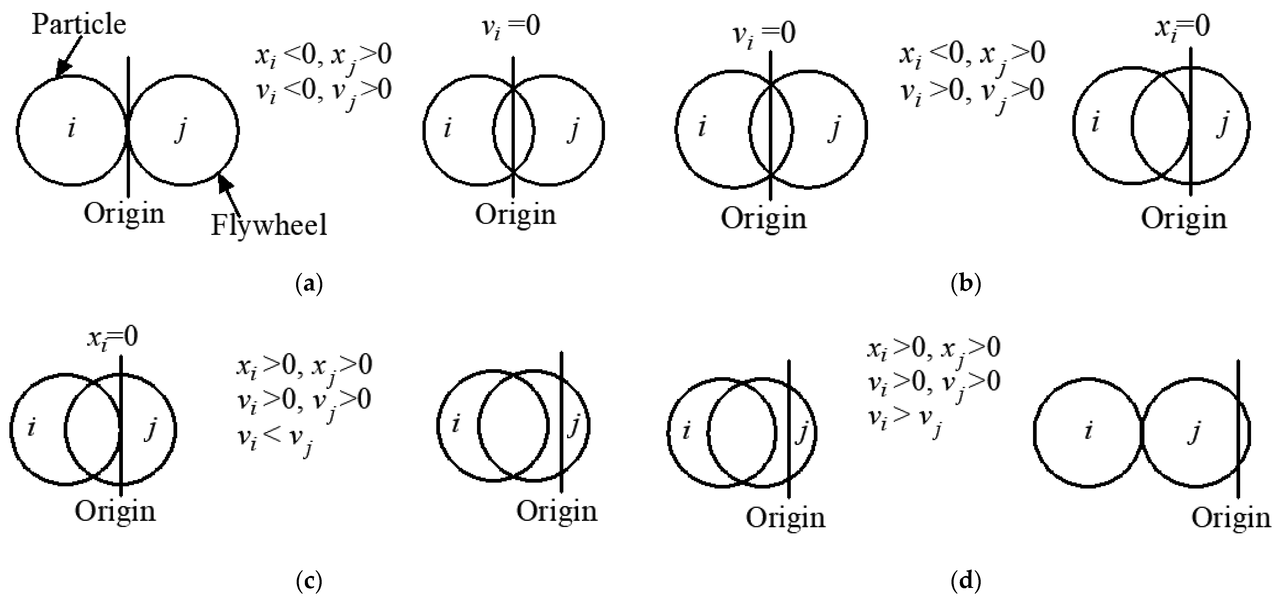
2.2. With Particle Collision

The analysis presented in Section 2.1 indicates that particle rolling friction has little influence on the amplification effect of the PID and the displacement response of the SDOF structure. Therefore, the influence of the frictional force of the particles can be ignored when the collision of particles is considered. In this case, the torque acting of PID can be expressed as:
T = J S α S + T i j ,
where Tij represents the impact force of particles on the flywheel relative to the torque of the flywheel shaft. In this study, it was assumed that the collision model between the flywheel and particles was the collision model of two soft balls [36]. Therefore, the equations of the movement of particles can be expressed as:
m i x ¨ i = F n ,
where Fn represents the normal contact force between the particle and flywheel wall. The Hertz contact theory [36] was cited to only consider normal contact force when particles collide with the flywheel wall. The expression of normal contact force of particles is shown in Equation (16):
F n = k n ( x f x i ) + 2 ξ m i k n ( x ˙ f x ˙ i ) ,
where ζ represents the normal damping ratio, xf represents the displacement of the flywheel, xi represents the displacement of particle i, and kn represents the normal contact stiffness (as shown in Equation (17) [36])
k n = 4 3 1 v i 2 E i + 1 v j 2 E j 1 r i 1 2 ,
where E represents the elastic modulus and v represents the Poisson ratio. Taking into consideration Equations (14)–(16), the dynamic equation of PID is obtained as:
T = J S α S + k n ( x f x i ) + c n ( x ˙ f x ˙ i ) r i m i x ¨ i = k n ( x f x i ) + c n ( x ˙ f x ˙ i ) .
Taking into consideration Equations (4) and (18), we derived:
T = 2 π J s P x ¨ d + k n [ ( 2 π r P ) x d x i ] + c n [ ( 2 π r P ) x ˙ d x ˙ i ] r i m i x ¨ i = k n [ ( 2 π r P ) x d x i ] + c n [ ( 2 π r P ) x ˙ d x ˙ i ] .
The Laplace transform of Equation (19) is obtained as:
X i ( s ) = 2 π r P ω i 2 + 2 ζ i ω i s s 2 + 2 ζ i ω i s + ω i 2 X d ( s ) .
Substituting s = ω0i into Equation (20), the modulus of the displacement transfer function is shown in Equation (21):
H ( i ω ) = 2 π r P 1 + 4 ζ i 2 α i 2 ( 1 α i 2 ) 2 + 4 ζ i 2 α i 2 ,
where α i = w 0 w i , ζ i = c n 2 m i w i   and   ω i = k n m i .
The movement state of particles in the cavity of flywheel was quite complicated under non-stationary excitation, such as earthquake excitation. Therefore, to obtain the analytical solution of the SDOF-PID system, the stationary excitation was commonly considered as the excitation, for example, harmonic excitation. In this case, the movement state of particles was stationary [2931]. When taking the harmonic excitation as an example, when the SDOF-PID system was stationary under a harmonic excitation, the particles would periodically collide with the cavity of the flywheel. In other words, the particles would provide periodically damping force and collision stiffness for the flywheel. Moreover, the analytical solution of controlled structure with damper was commonly used to optimize the parameters of new type of damper. In this case, a simple linear model of the nonlinear damper was normally used to optimize its parameters [27,29], especially for the nonlinear damper system. Therefore, we also simplified the PID to a linear system. It should be pointed out that an experimental study on the mechanical behaviour of PID needs to be conducted to verify the optimized parameters and method in future, and a study on the combination of discrete element and finite element methods also needs to be carried out to optimize the nonlinear system with PID.
Based on the aforementioned discussion, the entire collision process is divided into four stages according to the different directions of displacement and velocity between the flywheel and particles. The detail information of the four stages is shown in Appendix A. In general, this section takes the stage (1) as an example for analysis.
If H ( i ω ) = κ , then the displacement relationship between particles and PID is expressed as follows:
x i ( t ) = κ x d ( t ) .
Substituting Equation (22) into Equation (19) obtained:
T = 2 π J s P x ¨ d + k n [ ( 2 π r P ) + κ ] x d + c n [ ( 2 π r P ) + κ ] x ˙ d r
Taking into consideration Equations (5) and (23), the output expression of PID is as follows:
F I s = 4 π 2 J s P 2 x ¨ d + 2 π c n r [ ( 2 π r P ) + κ ] P x ˙ d + 2 π k n r [ ( 2 π r P ) + κ ] P x d .
Thus, the basic coefficients of the PID can be expressed as:
m i n = 4 π 2 J s P 2 = 2 π 2 ( r 2 + r 0 2 ) m 0 P 2 c d = 2 π c n r [ ( 2 π r P ) + κ ] P = 4 π 2 c n r r P 2 Φ 1 k d = 2 π k n r [ ( 2 π r P ) + κ ] P = 4 π 2 k n r r P 2 Φ 1 ,
where Φ 1 = P m i 2 ω 0 4 + ( P c n 2 2 P m i k n 2 π r c n 2 ) ω 0 2 + ( P + 2 π r ) k n 2 P m i 2 ω 0 4 + ( P c n 2 2 P m i k n ) ω 0 2 + P k n 2 .
Simplifying Փ1, Equation (25) can be expressed as:
m i n = 2 π 2 r 0 2 ( φ 2 + 1 ) P 2 m 0 c d = 4 π 2 r r 2 π r p P 3 c n k d = 4 π 2 r r 2 π r p P 3 k n ,
where φ = r / r 0 . In Equation (26), the ratio λ of the damping or stiffness coefficients between the PID and particle is given by:
λ = c d c n = k d k n = 4 π 2 r r 2 π r P P 3 .
Equations (26) and (27) show that the basic coefficients of PID are closely related to the ball screw lead. Further, the inertia coefficient of the PID collision is the same as that of the PID without a particle collision (Equation (8)). The influence curves of the screw lead, flywheel radius, and distance between the particle and flywheel centre on the ratio λ are shown in Figure 5.
Figure 5 shows that the ratio λ decreases with an increase in the screw lead. Under the same lead, λ increased with an increase in the distance between the particle and flywheel centre and the flywheel radius. Further, the smaller the lead, the greater the effect of λ was on the flywheel radius and the distance between the particle and flywheel centre. Combined with Equation (1) and Figure 1b, when particles collide, the equation of motion of the SDOF-PID can be simplified as:
m u ¨ + c u ˙ + k u + F I S = p ( t ) F I S = k s ( u x d ) m i n x ¨ d + c d x ˙ d + k d x d = F I S ,
If p(t) = −mag(t), then Equation (28) can be expressed as:
m u ¨ ( t ) + c u ˙ ( t ) + k u ( t ) + k s [ u ( t ) x d ( t ) ] = m a g t m i n x ¨ d ( t ) + c d x ˙ d ( t ) + k d x d ( t ) k s [ u ( t ) x d ( t ) ] = 0 .
Then, Equation (29) can be rewritten in a dimensionless form as:
u ¨ ( t ) + 2 ξ 1 ω u ˙ ( t ) + ω 2 u ( t ) + δ 1 ω 2 [ u ( t ) x d ( t ) ] = a g t μ x ¨ d ( t ) + 2 ξ 2 ω x ˙ d ( t ) + δ 2 ω 2 x d ( t ) δ 1 ω 2 [ u ( t ) x d ( t ) ] = 0 ,
where ω = k m , ω s = k s m , ξ 1 = c 2 m ω , ξ 2 = c d 2 m ω , μ = m i n m , δ 1 = k s k = ω s 2 ω 2   and   δ 2 = k d k .
Through the Laplace transform, Equation (30) can be expressed as:
U ( s ) = ( s 2 μ + 2 s ξ 2 ω + δ 1 ω 2 + δ 2 ω 2 ) A g ( s ) s 4 μ + 2 s 3 ( ξ 1 μ + ξ 2 ) ω + s 2 ( δ 1 + δ 2 + μ + δ 1 μ + 4 ξ 1 ξ 2 ) ω 2 + 2 s ( δ 1 + δ 2 ) ξ 1 + ξ 2 + ξ 2 δ 1 ω 3 + ( δ 1 + δ 2 + δ 1 δ 2 ) ω 4 .
X d ( s ) = δ 1 ω 2 A g ( s ) s 4 μ + 2 s 3 ( ξ 1 μ + ξ 2 ) ω + s 2 ( δ 1 + δ 2 + μ + δ μ + 4 ξ 1 ξ 2 ) ω 2 + 2 s ( δ 1 + δ 2 ) ξ 1 + ξ 2 + ξ 2 δ 1 ω 3 + ( δ 1 + δ 2 + δ 1 δ 2 ) ω 4 .
Thus, the frequency-domain transfer function is shown as:
H U ( i ω 0 ) = U ( s ) A g ( s ) s = i ω 0 .
H X d ( i ω 0 ) = X d ( s ) A g ( s ) s = i ω 0 .
Combined with Equations (30) and (34), the frequency-domain transfer function between the damping force of PID and the input excitation is as follows:
H F d ( i ω 0 ) = ( μ s 2 + 2 ξ 2 ω s + δ 2 ω 2 ) X d ( s ) A g ( s ) s = i ω 0 .
According to the random vibration theory [37], the root mean square (RMS) σY of the output response is as follows:
σ Y = H ( i ω 0 ) 2 S X ( ω 0 ) d ω 0 .
Equation (36) shows that the modulus of the transfer function must be provided to find the RMS of the output response. The square modulus of the transfer function can be obtained by taking into consideration Equations (33) and (36), as indicated in:
H U ( i α ω ) 2 = ( μ α 2 δ 1 δ 2 ) 2 + 4 ξ 2 2 α 2 D ( α , μ , ξ 1 , ξ 2 , δ 1 , δ 2 ) ω 4 ,
H F d ( i α ω ) 2 = δ 1 2 ( μ α 2 δ 2 ) 2 + 4 ξ 2 2 δ 1 2 α 2 D ( α , μ , ξ 1 , ξ 2 , δ 1 , δ 2 ) ,
where D ( α , μ , ξ 1 , ξ 2 , δ 1 , δ 2 ) = [ μ α 4 ( δ 1 + δ 2 + μ + δ 1 μ + 4 ξ 1 ξ 2 ) α 2 + ( δ 1 + δ 2 + δ 1 δ 2 ) ] 2 + 4 [ ( δ 1 ξ 1 + δ 2 ξ 1 + ξ 2 + δ 1 ξ 2 ) α ( ξ 1 μ + ξ 2 ) α 3 ] 2 .
Based on the above mentioned, if the input excitation SX(ω0) is considered as a constant S0 (white-noise excitation), the displacement ratio γ U and damping force ratio γ F d between the SDOF-PID and SDOF are, respectively, given by:
γ U ( μ , ξ 1 , ξ 2 , δ 1 , δ 2 ) = σ U σ U 0 = H U ( i α ω ) 2 S 0 ω d α H U 0 ( i α ω ) 2 S 0 ω d α = H U ( i α ω ) 2 d α H U 0 ( i α ω ) 2 d α .
γ F d ( μ , ξ 1 , ξ 2 , δ 1 , δ 2 ) = σ F d σ F d 0 = H F d ( i α ω ) 2 S 0 ω d α H F d 0 ( i α ω ) 2 S 0 ω d α = H F d ( i α ω ) 2 d α H F d 0 ( i α ω ) 2 d α .
Equations (39) and (40) indicate that the displacement ratio and damping force ratio of PID with particle collision are not related to the natural frequency w of SDOF; however, they are related to the stiffness ratio δ1, the natural damping ratio ξ1, the nominal damping ratio ξ2, the inertial mass ratio μ, and the nominal stiffness ratio δ2. Moreover, if the input excitation was more complicated, the final expression of the integrals in Equations (39) and (40) could be more complicated and not be given explicitly.

2.3. Displacement Response Characteristic of SDOF-PID

Without particle collision, the damping mechanism of PID was like that of the inertial damper, and the influence law of the parameters was consistent with that of the inertial damper [37]. Therefore, the displacement response analysis of the SDOF-PID with particle collision was only carried out in this section. A parameter study of SDOF-PID was conducted using the displacement ratio γ U (Equation (39)) in this study when the particles collided with the flywheel wall.
Considering SDOF with an inherent damping ratio ξ1 = 0.02 and stiffness ratio δ1 = 0.1 as an example, the μ-ξ2-δ2 spatial displacement response cloud diagram of SDOF-PID was established, as shown in Figure 6. The range of values of the parameters in Figure 6 is given by:
0.01 μ 1 0.01 ξ 2 1 0.01 δ 2 1 .
Figure 6 shows that the smaller the nominal stiffness ratio, the larger the area of better damping (blue area in Figure 6) that can be obtained was. In other words, the smaller the nominal stiffness ratio δ2, the larger the range of the mass ratio μ was; further, the nominal damping ratio ξ2 could be selected to ensure a better decreasing rate. Thus, the nominal stiffness ratio δ2 was set as 0.01 to continue studying other parameters.
Based on the practical application scenarios, the inherent damping ratio ξ1 of the SDOF were set as 0.02 for a steel structure and 0.05 for a concrete structure separately, and the nominal stiffness ratio δ2 was set as 0.01. On this basis, the μ-ξ2-δ1 spatial displacement response cloud diagram of the SDOF-PID was established, as shown in Figure 7. The range of values of the parameters in Figure 7 are given by:
0.01 μ 1 0.01 ξ 2 1 0.01 δ 1 1 .
Figure 7 shows that most of the optimal displacement response solutions of SDOF-PID appeared at the upper boundary of the cloud image. This indicated that there was no optimal solution for the displacement response of SDOF-PID without adding other constraints. However, a better solution of the displacement response of the SDOF-PID could provide a reasonable value range based on the cloud image (blue region in the figure). The range of the inherent damping ratio of the PID had significant influence on the range of values for the optimal solution. The larger the inherent damping ratio is, the smaller the range of values for the optimal solution will be (as shown in Figure 7c,d). Moreover, the optimal solution of the displacement response of the SDOF-PID was within the given parameter range when the nominal damping ratio was very small (ξ2 < 0.1). However, the reasonable value range for the optimal solution was very small. It should be pointed out that there was little influence of the nominal damping ratio of the PID on the range of values for the optimal solution when the stiffness ratio was very small (δ1 < 0.1). Figure 7e shows that the damping effect of the PID was not obvious when the stiffness ratio was very small (δ1 < 0.1).

3. Damping Effect of PID

3.1. Parameter Optimization

To verify the damping effect of PID, the parameter optimization of SDOF-PID needs to be carried out. In this study, the parameters of the SDOF-PID are optimised using fixed-point theory [38] and the performance-cost control principle [39,40]. The fixed-point theory takes the minimum amplitude of a certain parameter of the system (such as displacement, acceleration, etc.) as the limitation condition for parameter optimization design, which can only be applied on the system with none or little inherent damping ratio. While the performance–cost theory takes the minimum damper output (control cost) as the limitation condition for parameter optimization design, which not only considers the damping effect of a damper, but also chooses a more economical damping method. Therefore, the damper optimized by the fixed-point theory can maximize the damping effect of the damper, but its control cost is relatively high. However, the performance cost control theory can reduce the control cost while ensuring the target damping effect.

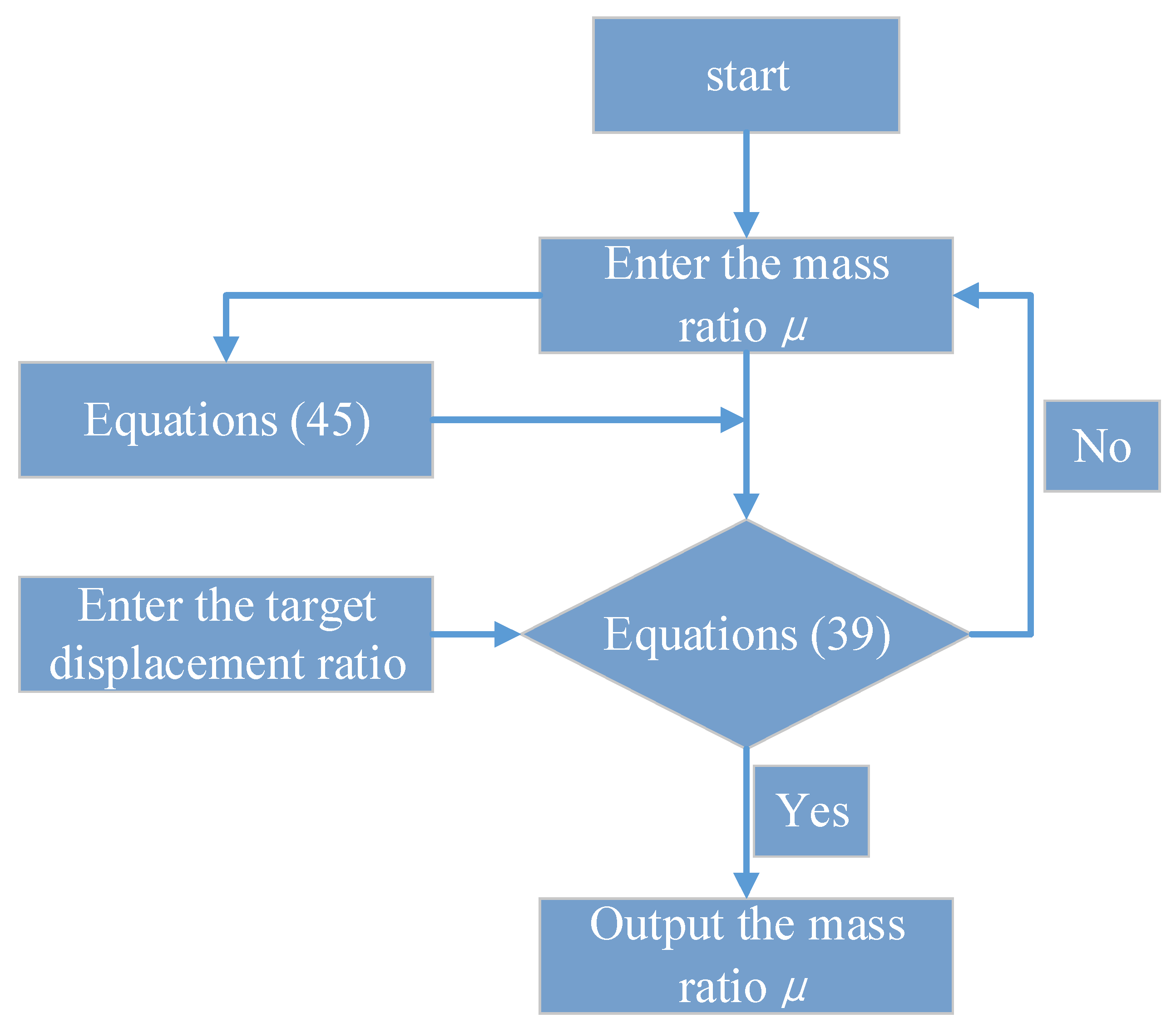
3.1.1. Fixed Point Theory

Considering the minimum displacement amplitude as the optimisation condition, the parameter of the SDOF-PID system can be optimised based on the fixed-point theory. In this case, the inherent damping ratio of the SDOF is neglected, and the equation of motion of the SDOF-PID system can be expressed as following:
m u ¨ + k u + F I S = p ( t ) F I S = k s ( u x d ) m i n x ¨ d + c d x ˙ d + k d x d = k s ( u x d ) .
Based on the mechanical model of SDOF-PID, the displacement transfer function of the system can be derived as follows:
H U p ( i α ω ) 2 = ( μ α 2 δ 1 δ 2 ) 2 + 4 ξ 2 2 α 2 D p ( α , μ , ξ 2 , δ 1 , δ 2 ) ω 4 ,
where D p ( α , μ , ξ 2 , δ 1 , δ 2 ) = [ μ α 4 ( δ 1 + δ 2 + μ + δ 1 μ ) α 2 + ( δ 1 + δ 2 + δ 1 δ 2 ) ] 2 + 4 [ ( ξ 2 + δ 1 ξ 2 ) α ξ 1 μ α 3 ] 2 .
According to the fixed-point theory, two conditions should be met to obtain the optimisation parameters: (1) the amplitudes of P and Q at the fixed points should be equal, and (2) an extreme value should be obtained at the fixed point. Thus, the optimal nominal damping ratio ξ 2 * and stiffness ratio δ 2 * are given by:
ξ 2 * = 3 μ 2 ( μ δ 2 ) 2 ( 1 δ 2 ) 4 ( 1 μ ) ( 2 μ + 2 μ δ 2 2 2 μ δ 2 μ 2 δ 2 2 ) δ 1 * = μ δ 2 1 μ .
Equation (45) indicates that the optimal nominal damping ratio ξ 2 * and stiffness ratio δ 1 * are both related to the mass ratio μ and nominal stiffness ratio δ2. Simultaneously, the fixed-point theory does not consider the influence of the inherent damping of the SDOF. Therefore, ξ 2 * and δ 1 * obtained by the fixed-point theory can be used as approximations for the SDOF-PID with smaller inherent damping [41].
According to the above theory, the parameter optimization process of the fixed-point theory is as follows: (1) the nominal stiffness ratio (δ2) is supposed first. (2) Subsequently, the Equations (44) and (45) and the displacement transfer function of the original structure without inherent damping are substituted into Equation (39) to obtain the displacement ratio function expression only about the mass ratio (μ). (3) Finally, the target displacement ratio is supposed, and the optimal stiffness ratio (δ1) and optimal nominal damping ratio (ξ2) will be obtained when the input mass ratio (μ) makes the Equation (39) reach target displacement ratio. The parameter optimization process of the fixed-point theory is shown in Figure 8.

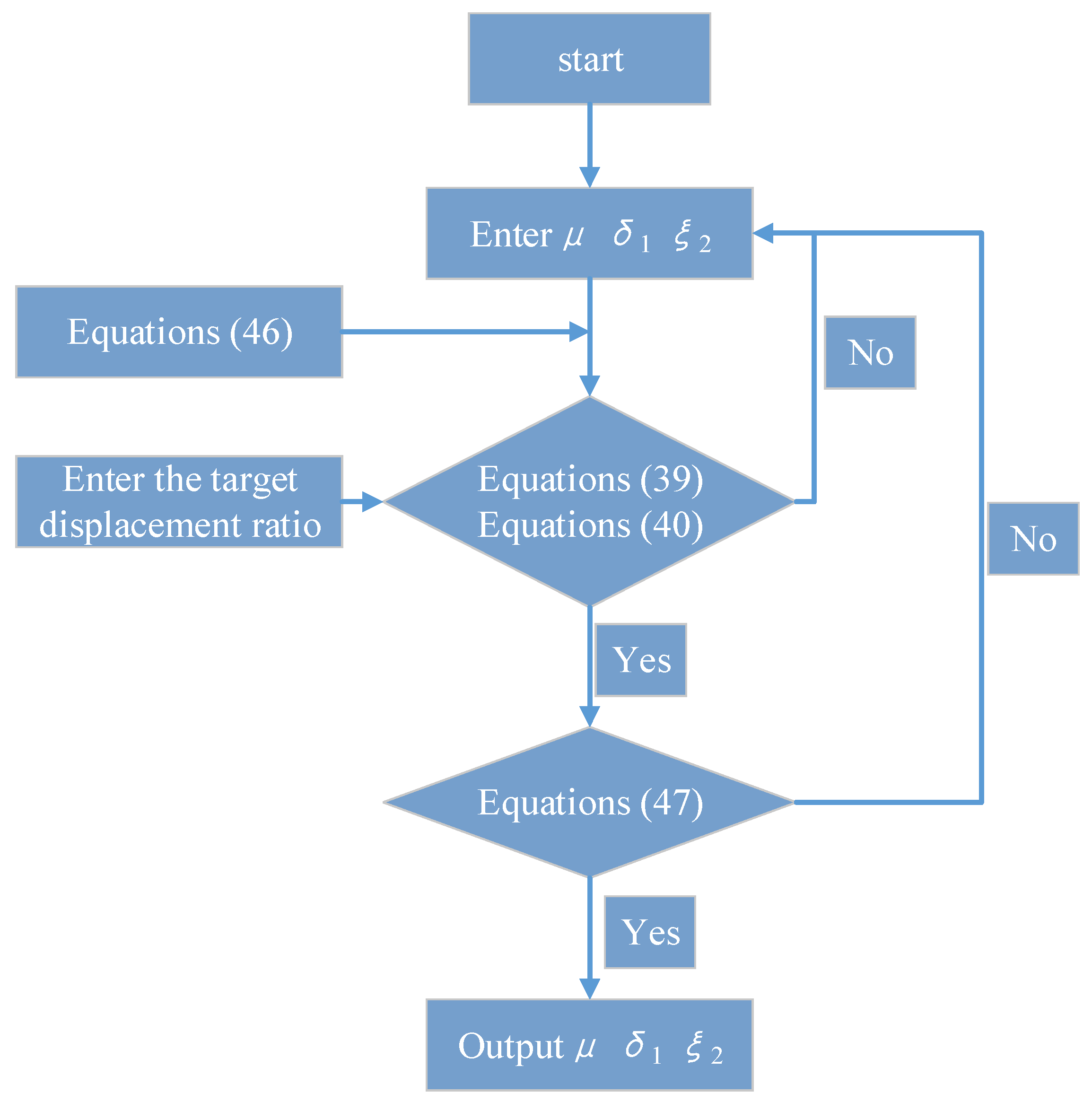
3.1.2. Performance–Cost Theory

The ‘performance–cost’ control principle of the RMS σ U of the displacement response of SDOF-PID (Equation (39) in Section 2.2) is represented as the damping effect (performance); the RMS σ F d of damping force response of PID (Equation (40) in Section 2.2) is represented as the cost control. Based on the design principle of coordination between the damping effect and cost control, the RMS σ F d of the damping force response of the PID is selected as the objective function, and the RSM σ U of the displacement response of the SDOF-PID does not exceed the maximum allowable value as the constraint condition:
min μ , ξ 2 , δ 1 σ F d μ , ξ 2 , δ 1 s . t . σ U μ , ξ 2 , δ 1 σ U μ min μ μ max ξ 2 min ξ 2 ξ 2 max δ 1 min δ 1 δ 1 min ,
where [σU] represents the maximum allowable value of σU determined according to the desired performance objective.
The constraint condition was added according to Equations (39) and (40) to reflect the degree of improvement in the inertial action on the energy dissipation capacity of the damping particle, which is given as:
ψ = σ U 0 ξ 1 σ U μ , ξ 2 , δ 1 σ U 0 ξ 1 σ U 0 ξ 1 + ξ 2 ψ 0   ,
where ψ represents the capacity of the inertial action to improve the energy dissipation of the damping particle. The value range of ψ0 is 1   <   ψ 0 2 , and the value in this study is 1.5. Equations (46) and (47) suggest that the computer program for the parameter optimisation design of SDOF-PID is written in MATLAB, and the subsequent parameter optimisation design is carried out.
According to the above theory, the parameter optimization process of performance-cost control theory is as follows: (1) the damping ratio (ξ1) and nominal stiffness ratio (δ2) are supposed, (2) then the Equations (39), (40), (46), and (47) are combined; the relationship function among mass ratio (μ), stiffness ratio (δ1) and nominal damping ratio (ξ2) can be obtained. (3) Finally, the optimal mass ratio (μ), stiffness ratio (δ1), and nominal damping ratio (ξ2) can be obtained under the constraints condition of Equations (47) and (46). The parameter optimization process of performance–cost control theory is shown in Figure 9.

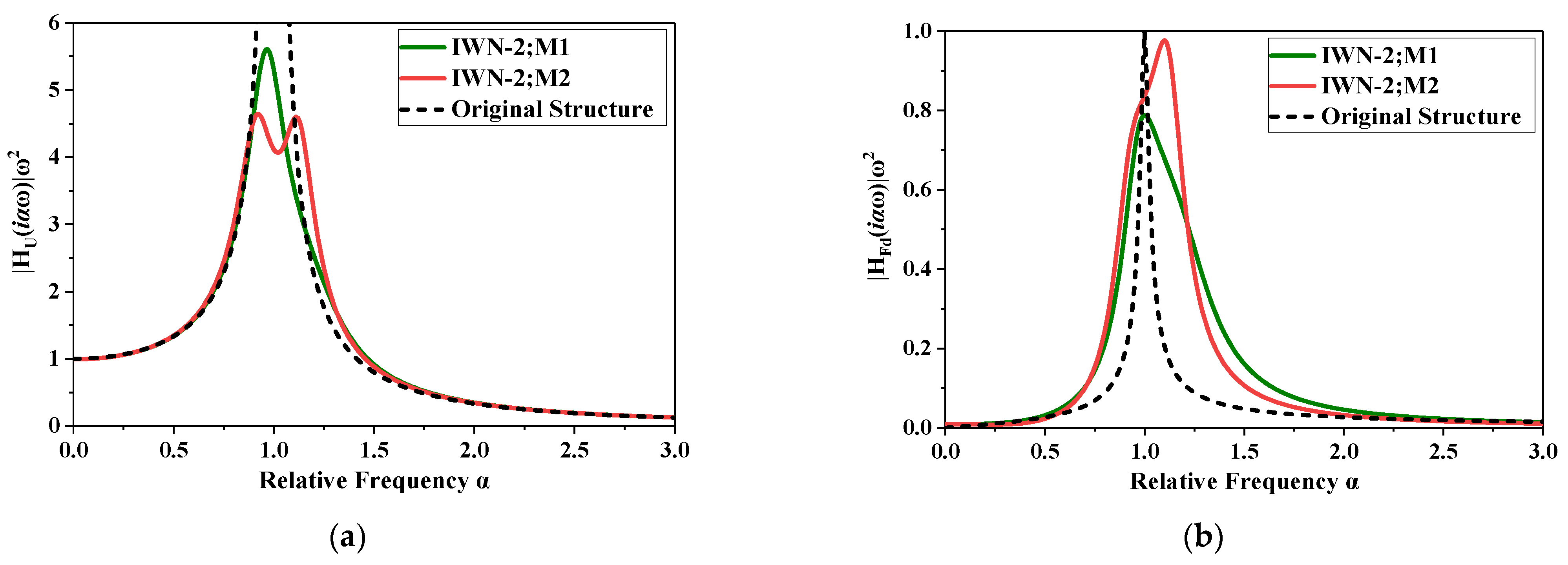
3.2. Parameter Optimization of the SDOF with Different Dampers

Without loss of generality, a SDOF is selected as the controlled structure. In practice, a SDOF is generally used to simplify a structure which has dominate first vibration mode, including a single layer structure and multi-layer structure with a dominant first vibration mode (the first-order participant mass ratio of a multi-layer structure is larger than 70%). As reported in Section 2, the smaller the nominal stiffness ratio of the SDOF-PID, the more obvious the damping effect of the PID on the SDOF is. Meanwhile, the optimisation design method based on fixed-point theory is only suitable for an SDOF with a small inherent damping. Therefore, the inherent damping ratio and nominal stiffness ratio of the SDOF-PID are 2% and 1%, respectively.
In practice, the design response spectrum is first designed based on the seismic design code, such as Specifications for Seismic Design of Highway Bridges (JTG/T 2231-01-2020) and Code for design of concrete structures (GB 50010-2010). Then, we can generate artificial earthquake records or select natural earthquake records from PEER centre, which are fit with the design response spectrum. Finally, we can carry out a dynamic analysis of the controlled structure under the determined seismic waves. Based on the above discussion, the response spectrum analysis can also describe the dynamic response of the controlled structure to a certain extent, especially for a nonlinear system, which cannot be simply constructed and analysed in finite element platform. Therefore, this study optimized the parameters of the PID by using the Kanai–Tajiki’s spectrum as a parameter optimization design condition and validated the damping effect of the PID based on a single freedom system under the seismic waves, which complied with the Kanai–Tajiki’s spectrum.
Based on the fixed-point theory and the ‘performance-cost’ control principle, a series of optimisation designs of the SDOF with different dampers are conducted using the same displacement damping rate as the optimisation objective. The design conditions are listed in Table 1, and the optimised design results are listed in Table 2. It should be pointed out that the PID first plays a tuning role on the controlled structure; meanwhile, the additional damping of inertia particles is used to dissipate the energy absorbed by the damper. Therefore, the tuning and damping effect of the PID is more likely to those of the TMD. Accordingly, a traditional TMD was also designed to compare with the PID. Moreover, to optimize the damper parameters under the most severe seismic excitation, the power spectral density function of white noise in Equations (39) and (40) should be replaced by that of the most severe seismic excitation.
Table 2 indicates that the design parameter of the SDOF with the damper increased when the displacement ratio γ U decreased from 0.60 to 0.50. The stiffness ratio δ1 increases the most; the corresponding damping force ratio γ F d (control cost) also increases. The design parameters under white noise excitation and the most severe seismic excitation are the same with the same optimisation method and displacement ratio γ U . Therefore, the most severe seismic excitation can be simplified to white noise excitation in the parameter optimisation design of the SDOF with the damper.
Compared to the design parameters of the different optimisation design methods, the nominal damping ratio ξ2 and stiffness ratio δ1 obtained by the fixed-point theory are both smaller than those obtained by the ‘performance–cost’ control principle under the same displacement ratio γ U . However, the damping force ratio γ F d (control cost) is larger than that based on the ‘performance–cost’ control principle. Under the optimization design method based on fixed-point theory, the added mass of the PID is nearly thousands of times less than that of the TMD when the same displacement ratio γ U is achieved; this reflects the superiority of the inertial amplification effect of the PID. According to Table 2, the transfer function curve of the displacement response of the SDOF-PID and the damping force response of the PID are presented in Figure 10.
Figure 10 shows that the displacement damping effect of the SDOF is the best after the PID arrangement (Figure 10a) when the input frequency is close to the inherent frequency (α = 1). Further, the PID can provide an optimal damping force for the SDOF over a wide range of frequency bands (Figure 10b). Compared with dampers designed by the two optimisation methods, optimisation method M1 (the ‘performance–cost’ control principle) reduced the damping force of the PID to the SDOF and effectively reduced the control cost under the same displacement ratio. However, the displacement damping effect of the PID designed by optimisation method M1 was worse than that of M2 (fixed-point theory) at the resonance time. In addition, the PID designed by optimisation method M1 has poor robustness to the SDOF, which decreases the width of the damping band. The PID designed by optimisation method M2 has a relatively better robustness to the SDOF, and the width of the damping band is large.
It should be mentioned that the optimization strategies, which is suitable to the PID are still the hotspot study in recent years. If the specific optimization strategies of the PID is expand, the damping effectiveness of the PID will be significantly enhanced. However, it is still huge challenge to constructing optimization strategies for the PID or the ID. This study has only proven that the traditional optimization strategies for the tuned mass damper (TMD) can be used to optimize the PID. New optimization methods for the PID considering its high nonlinear characteristic need to be proposed and verified in the future. Moreover, the PID also belongs to the inertia type of damper. Therefore, PID can be replaced with other inertia type of dampers, such as viscous inertial dampers (VID) [37,39,40]. Compared to the VID, the PID do not require later maintenance and have a wide tuning frequency band. However, due to the introduction of particles, the nonlinearity of the dampers is relatively high, and the theoretical analysis is relatively complex.

3.3. Damping Effect Analysis

Based on the aforementioned parameter optimization result, a single degree of freedom system with a mass and stiffness of 1200 t and 180,000 kN/m was selected as the controlled structure. We assumed that the target displacement ratio (the peak displacement ratio of the SDOF with and without damping) was 0.60; the arranged number of the PID was 5. In this case, the optimized nominal damping ratio ξ2 of one PID was 0.0006. According to the Equations (26) and (30), the damping coefficient of the damping particles approximated to be in the range of 0.001 N·s/m–0.01 N·s/m with practical filling ratio. Therefore, common materials can be used as the material of damping particles to meet the damping coefficient requirements of the PID, such as lead, cast iron, steel, and glass.
Following with the above design parameters, the displacement time–history curves of the SDOF-PID designed using different optimisation design methods are presented in Figure 11. The displacement time–history curves of the SDOF with different dampers designed using the fixed-point theoretical optimisation design method are illustrated in Figure 12.
Figure 11 and Figure 12 show that the PID optimised based on the fixed-point theory and ‘performance–cost’ theory shows a good damping effect. Moreover, the damping effect of the PID under the most severe seismic excitation is better than that under white noise excitation, which implies that the damping control effect of the PID under broadband excitation (actual ground motion) needs to be explored further. The PID and TMD can achieve the same damping effect under the same displacement decreasing rate. However, the additional mass of the PID is only one thousandth that of the TMD, and the PID has an obvious superiority.
Based on the aforementioned discussion, the PID can sufficiently decrease its additional mass ratio to provide an effective damping effect as that of TMD. In actuality, the control effect of the PID, ID, or TMD all include a tuning and damping effect. The tuning effect of these dampers plays a crucial role in controlling the peak dynamic response of a controlled structure. The damping effect is more sufficient to decrease the mean dynamic response of a controlled structure. Therefore, the additional mass ratio of these dampers should not be too small. However, the additional mass ratio of these dampers cannot be too large to impact the traditional design parameters of the control structure. Take TMD as an example; its optimized additional mass ratio is about 2~3%. Theoretically, the optimized additional mass ratio of the PID is only 0.2%~0.3% based on this study. Therefore, the application condition or design parameters of the PID can be widely relaxed. PID can provide a stronger case for its cost-effectiveness and potential weight savings compared with a traditional TMD.

4. Conclusions

In this study, a particle-inertial damper (PID) was proposed, and a mechanical model of a single-degree-of-freedom (SDOF) structure with a non-collision and collision PID was established. Further, the influence of particle rolling friction and particle collision on the inertial amplification capacity as well as the dynamic response of the SDOF structure with a non-collision and collision PID were analysed systematically. Finally, the control effects of the PID and tuned mass damper (TMD) were compared based on two typical optimisation methods. The main conclusions are as follows:
(1)
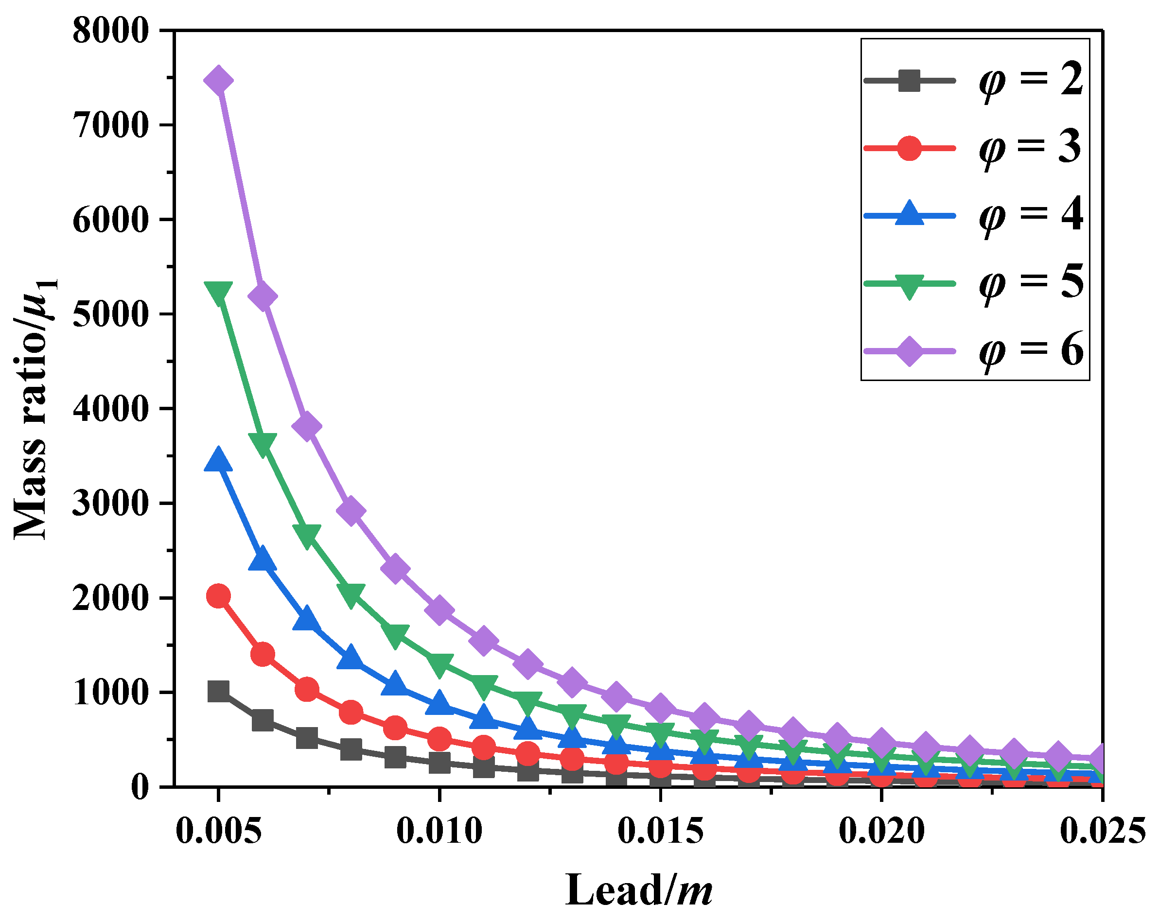
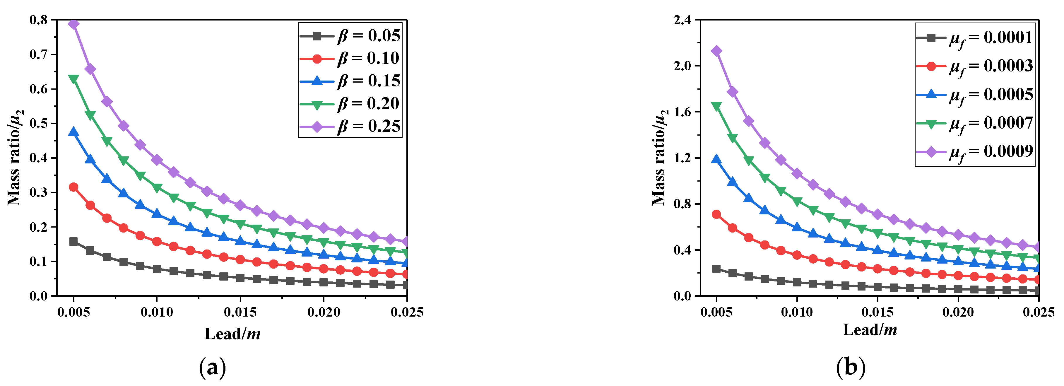
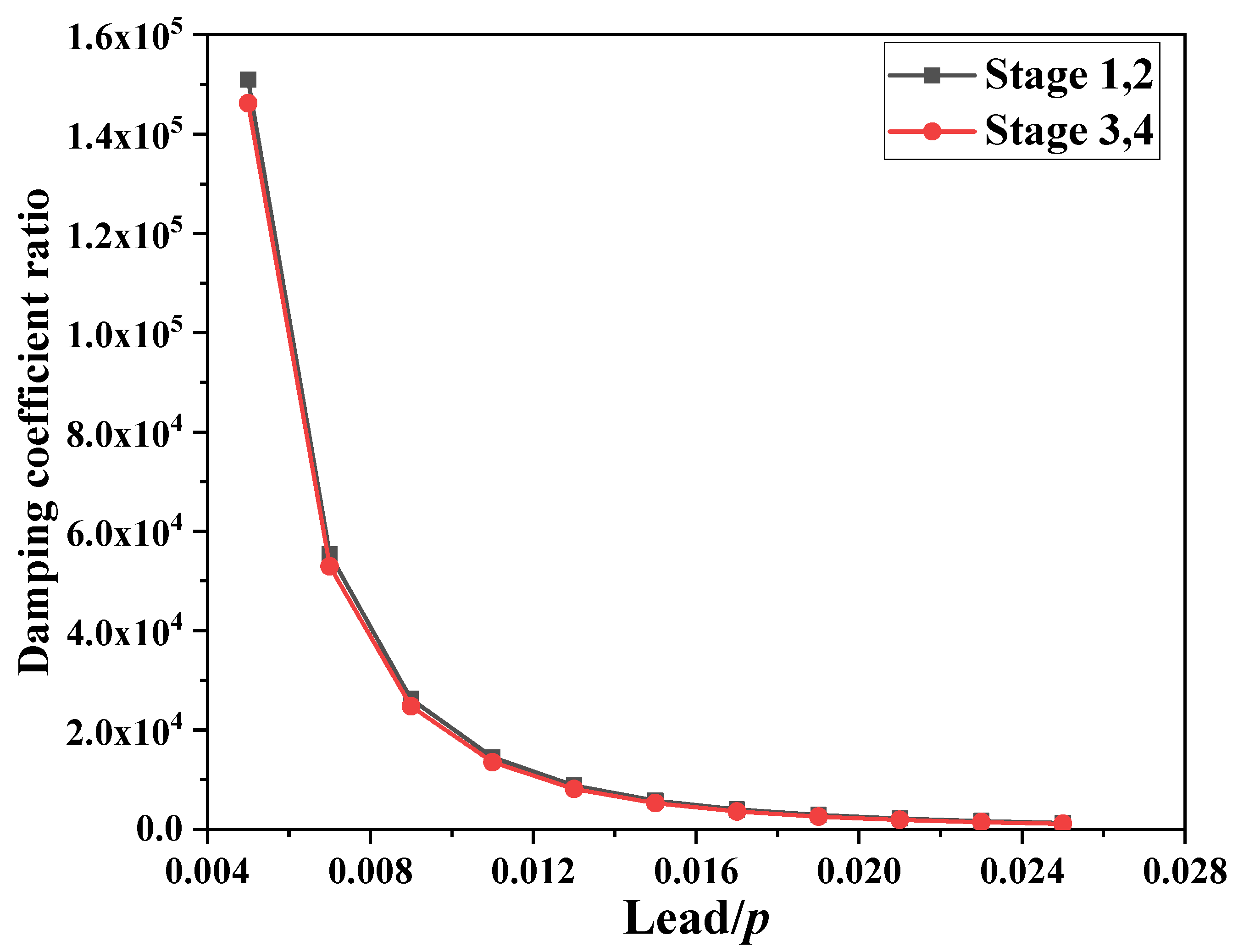
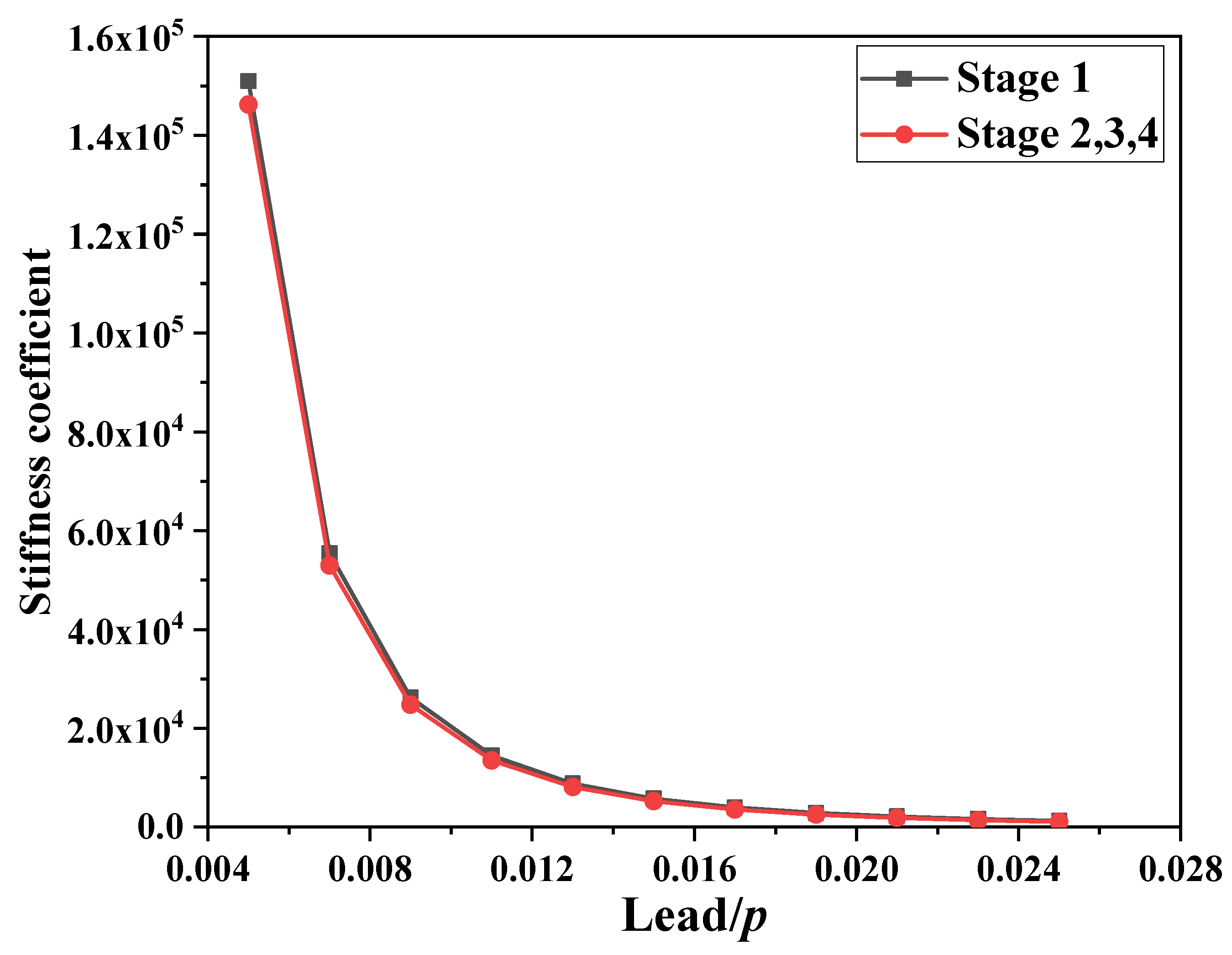
The mechanical model of the SDOF-PID considering particle rolling friction and particle collision can be used for analysing the damping effect and damping mechanism of the PID and for the relevant dynamic response of the SDOF. Without particle collision, the particle rolling friction has little influence on the inertia amplification effect of the PID and displacement response of the SDOF-PID. Under harmonic excitation, the damping mechanism of the PID is affected significantly by its equivalent inertia coefficient, equivalent damping coefficient, and equivalent stiffness coefficient considering particle collision. These equivalent parameters are significantly influenced by the lead of the ball screw. Theoretically, the damping coefficient and stiffness of the proposed PID can be amplified thousands of times with certain optimized parameters;
(2)
The PID optimised based on fixed-point theory has a wide damping band for the SDOF. However, the fixed-point theory can result in a higher damping force (control cost) for the PID. The PID optimised by the ‘performance–cost’ theory can effectively reduce the output of the damping force (control cost) without affecting the rate of a decrease in displacement. However, the ‘performance–cost’ theory may induce poor robustness and a narrower damping band in the PID;
(3)
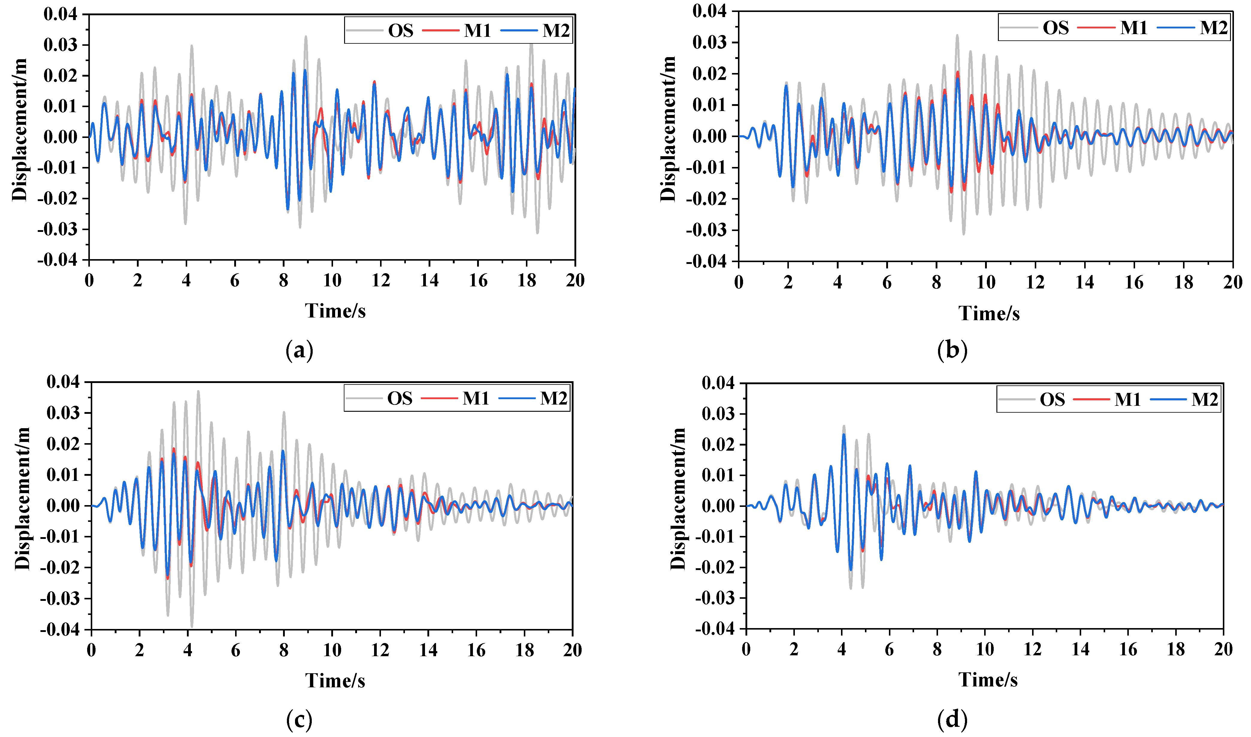
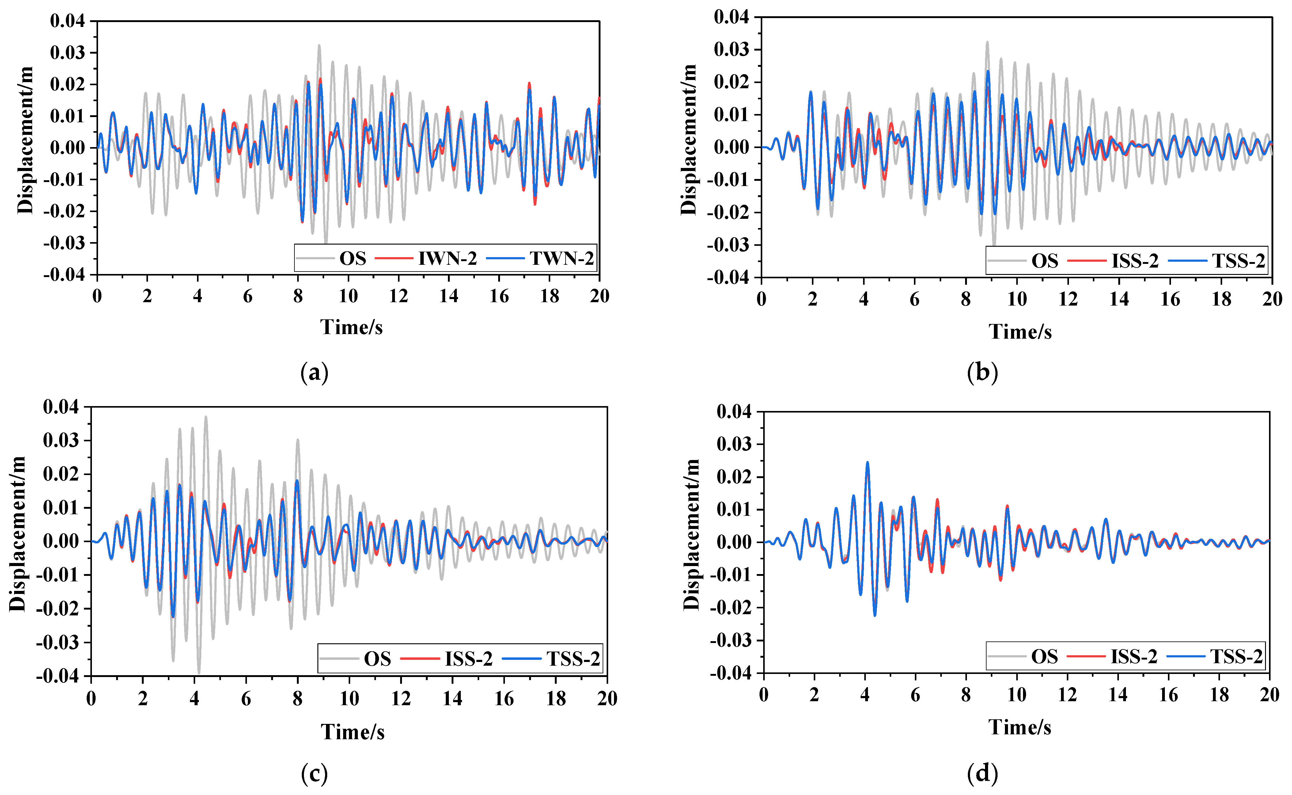
The damping effect of the PID on the SDOF under the most severe seismic excitation is better than that of the PID under white noise excitation. The damping effect of the PID under broadband excitation (actual ground motion) needs further exploration. Under the same damping capacity demand, the additional mass ratio of the PID is only one thousandth that of the TMD;
(4)
An equivalent linearization model of the PID can be used to optimize its design parameters without considering the high nonlinear characteristic. Therefore, the model of the PID needs to be verified through subsequent experiments. Moreover, the effective analysis methods of the PID or PID-controlled structure system need to be proposed and verified with considering the high nonlinear characteristic in future.

Author Contributions

Writing—original draft, M.X.; Writing—review & editing, W.X., J.W., Y.C., D.Z., L.H., Y.S. and Y.L. All authors have read and agreed to the published version of the manuscript.

Funding

This research was funded by the National Natural Science Foundation of China (Grant No. 52178446, 51908015, 51978021, 52108428), Beijing Natural Science Foundation (8232001), Key R&D projects of Hebei Province in China (Grant No. 21375403D) and Natural Science Foundation of Hebei Province in China (Grant No. E2020210017).

Data Availability Statement

Not applicable.

Conflicts of Interest

The authors declare no conflict of interest.

Appendix A

Under harmonic excitation, according to the different directions of displacement and velocity between the flywheel and particles, the entire collision process is divided into four stages, as show in Figure A1.
Figure A1. Collision process between particle and flywheel. (a) Stage 1, (b) Stage 2, (c) Stage 3, (d) Stage 4.
Buildings 13 02264 g0a1
(1)
Stage 1
Setting H ( i ω ) = κ and x d = X d e i ω t (harmonic excitation), the displacement relationship between particles and PID is expressed as follows:
x i ( t ) = κ x d ( t ) x ˙ i ( t ) = κ x ˙ d ( t ) .
Substituting Equation (A1) into Equation (19), we obtain:
T = 2 π J s P x ¨ d + k n [ ( 2 π r P ) + κ ] x d + c n [ ( 2 π r P ) + κ ] x ˙ d r ,
The force of the PID can be obtained by taking into consideration (4) and (A2) as:
F I s = 4 π 2 J s P 2 x ¨ d + 2 π c n r [ ( 2 π r P ) + κ ] p x ˙ d + 2 π k n r [ ( 2 π r P ) + κ ] p x d .
Combined with (21), the parameters of the PID are given as:
m i n = 4 π 2 J s P 2 = 2 π 2 ( r 2 + r 0 2 ) m 0 p 2 c d = 2 π c n r [ ( 2 π r P ) + κ ] p = 4 π 2 c n r r p 2 Φ 1 k d = 2 π k n r [ ( 2 π r P ) + κ ] p = 4 π 2 k n r r p 2 Φ 1 ,
where Φ 1 = p m i 2 ω 0 4 + ( p c n 2 2 p m i k n + 2 π r c n 2 ) ω 0 2 + ( p + 2 π r ) k n 2 p m i 2 ω 0 4 + ( p c n 2 2 p m i k n ) ω 0 2 + p k n 2 .
Simplifying Փ1, Equation (A4) can be expressed as:
m i n = 4 π 2 J s P 2 = 2 π 2 ( r 2 + r 0 2 ) m 0 p 2 c d = 4 π 2 c n r r 2 π r p + p 2 p 3 k d = 4 π 2 k n r r 2 π r p + p 2 p 3 .
(2)
Stage 2
Setting H ( i ω ) = κ , the displacement relationship between particles and PID is expressed as follows:
x i ( t ) = κ x d ( t ) x ˙ i ( t ) = κ x ˙ d ( t ) .
Substitute Equation (A6) into Equation (19) and combine it with (21); then, the parameters of PID are shown as:
m i n = 4 π 2 J s P 2 = 2 π 2 ( r 2 + r 0 2 ) m 0 p 2 c d = 4 π 2 c n r r 2 π r p + p 2 p 3 k d = 4 π 2 k n r r 2 π r p p 2 p 3 .
(3)
Stage 3
Setting H ( i ω ) = κ , the displacement relationship between particles and PID is expressed as follows:
x i ( t ) = κ x d ( t ) x ˙ i ( t ) = κ x ˙ d ( t ) .
Substitute Equation (A8) into Equation (19) and combine with (21); the parameters of PID are expressed as:
m i n = 4 π 2 J s P 2 = 2 π 2 ( r 2 + r 0 2 ) m 0 p 2 c d = 4 π 2 c n r r 2 π r p p 2 p 3 k d = 4 π 2 k n r r 2 π r p p 2 p 3 .
(4)
Stage 4
Setting H ( i ω ) = κ , the displacement relationship between particles and PID is expressed as follows:
x i ( t ) = κ x d ( t ) x ˙ i ( t ) = κ x ˙ d ( t ) .
Substitute Equation (A10) into Equation (19) and combine it with (21); then, the parameters of the PID are given as:
m i n = 4 π 2 J s P 2 = 2 π 2 ( r 2 + r 0 2 ) m 0 p 2 c d = 4 π 2 c n r r 2 π r p p 2 p 3 k d = 4 π 2 k n r r 2 π r p p 2 p 3
λ = c d c n = k d k n .
Equations (A5), (A7), (A9) and (A11) show that the equivalent inertia coefficient, equivalent damping coefficient, and equivalent stiffness coefficient of the PID are closely related to the lead of the ball screw. The relationship between the damping coefficient ratio and lead as well as the relationship between the stiffness coefficient ratio and lead are shown in Figure A2 and Figure A3.
Figure A2 and Figure A3 show that the damping and stiffness coefficient ratios obtained in the four stages show little difference. Therefore, Equations (A5), (A7), (A9) and (A11) can be simplified further to Equation (A13):
m i n = 2 π 2 ( r 2 + r 0 2 ) p 2 m 0 c d = 4 π 2 r r 2 π r p p 3 c n k d = 4 π 2 r r 2 π r p p 3 k n

References

  1. Fricke, J.R. Lodengraf damping: An advanced vibration damping technology. SV Sound Vib. 2000, 34, 22–27. [Google Scholar]
  2. Panossian, H.V. Structural damping enhancement via Non-obstructive particle damping technique. J. Vib. Acoust. 1992, 114, 101–105. [Google Scholar] [CrossRef]
  3. Mao, K.; Wang, M.Y.; Xu, Z.; Chen, T. Simulation and characterization of particle damping in transient vibrations. J. Vib. Acoust. 2004, 126, 202–211. [Google Scholar] [CrossRef]
  4. Lieber, P.; Jensen, D.P. An acceleration damper: Development, design and some application. Trans. Am. Soc. Mech. Eng. 1945, 67, 523–530. [Google Scholar] [CrossRef]
  5. Zhang, K.; Chen, T.; Wang, X.; Fang, J. Rheology behavior and optimal damping effect of granular particles in a Non-obstructive particle damper. J. Sound Vib. 2015, 364, 30–43. [Google Scholar] [CrossRef]
  6. Paget, A.L. Vibration in steam turbine buckets and damping by impacts. Engineering 1937, 143, 305–307. [Google Scholar]
  7. Grubin, C. On the theory of the acceleration damper. J. Appl. Mech. 1956, 23, 373–378. [Google Scholar] [CrossRef]
  8. Masri, S.F.; Caughey, T.K. On the stability of the impact damper. J. Appl. Mech. 1966, 33, 586–592. [Google Scholar] [CrossRef]
  9. Masri, S.F. Analytical and experimental studies of multiple-unit impact dampers. J. Acoust. Soc. Am. 1969, 45, 1111–1117. [Google Scholar] [CrossRef]
  10. Saeki, M. Analytical study of multi-particle damping. J. Sound Vib. 2005, 281, 1133–1144. [Google Scholar] [CrossRef]
  11. Yan, W.; Wang, B.; He, H. Research of mechanical model of particle damper with friction effect and its experimental verification. J. Sound Vib. 2019, 460, 114898. [Google Scholar]
  12. He, H.; Wang, B.; Yan, W. Mechanical model and optimization analysis of multiple unidirectional single particle damper. J. Eng. Mech. 2021, 147, 1–19. [Google Scholar] [CrossRef]
  13. Lu, Z.; Ma, N.; Zhou, C. Multi-objective optimization design of multiple tuned impact dampers. J. Vib. Shock 2022, 41, 33–41. [Google Scholar]
  14. Akbar, M.A.; Wong, W.O.; Rustighi, E. A Hybrid Damper with Tunable Particle Impact Damping and Coulomb Friction. Machines 2023, 11, 545. [Google Scholar] [CrossRef]
  15. Papalou, A.; Masri, S.F. An experimental investigation of particle dampers under harmonic excitation. J. Vib. Acoust. 1998, 4, 361–379. [Google Scholar] [CrossRef]
  16. Friend, R.D.; Kinra, V.K. Particle impact damping. J. Sound Vib. 2000, 233, 93–118. [Google Scholar] [CrossRef]
  17. Saeki, M. Impact damping with granular materials in a horizontally vibrating system. J. Sound Vib. 2002, 251, 153–161. [Google Scholar] [CrossRef]
  18. Pendleton, S.; Basile, J.; Guerra, J.; Tran, B.; Ogomori, H.; Lee, S. Particle damping for launch vibration mitigation: Design and test validatio. In Proceedings of the 4th AIAA Multidisciplinary Design Optimization Specialists Conference, Schaumburg, IL, USA, 7–10 August 2008; pp. 7–10. [Google Scholar]
  19. Wang, X.; Liu, X.; Shan, Y.; He, T. Design, simulation and experiment of particle dampers attached to a precision instrument in spacecraft. J. Vibroeng. 2015, 17, 1605–1614. [Google Scholar]
  20. Lu, Z.; Lu, X.; Lu, W.; Masri, S.F. Experimental studies of the effects of buffered particle dampers attached to a multi-degree-of-freedom system under dynamic loads. J. Sound Vib. 2012, 331, 2007–2022. [Google Scholar] [CrossRef]
  21. Lu, Z.; Huang, B.; Zhou, Y. Theoretical study and experimental validation on the energy dissipation mechanism of particle dampers. Struct. Control Health Monit. 2018, 25, e2125. [Google Scholar] [CrossRef]
  22. Yan, W.; Xu, W.; Wang, J.; Chen, Y. Experimental Research on the Effects of a Tuned Particle Damper on a Viaduct System under Seismic Loads. J. Bridge Eng. 2014, 19, 04013004. [Google Scholar] [CrossRef]
  23. Luo, Z.; Yan, W.; Xu, W.; Zheng, Q.; Wang, B. Experimental research on the multilayer compartmental particle damper and its application methods on long-period bridge structures. Front. Struct. Civ. Eng. 2019, 13, 751–766. [Google Scholar] [CrossRef]
  24. Lu, Z.; Huang, Z.K. Analytical and experimental studies on particle damper used for tremor suppression. J. Vib. Control 2021, 27, 2887–2897. [Google Scholar] [CrossRef]
  25. Lu, Z.; Zhang, Q.Q.; Fan, Q.Q.; Li, Q. Studies on dissipative characteristics and equivalent model of particle damper in railway application. J. Sound Vib. 2023, 560, 117788. [Google Scholar] [CrossRef]
  26. Papalou, A.; Masri, S.F. Performance of particle dampers under random excitation. J. Vib. Acoust. 1996, 118, 614–621. [Google Scholar] [CrossRef]
  27. Lu, Z.; Chen, X.; Zhou, Y. An equivalent method for optimization of particle tuned mass damper based on experimental parametric study. J. Sound Vib. 2018, 419, 571–584. [Google Scholar] [CrossRef]
  28. Huang, X.H.; Xu, W.B.; Yan, W.M. Equivalent model of a multiparticle damper considering the mass coupling coefficient. Struct. Control Health Monit. 2020, 27, e2580. [Google Scholar] [CrossRef]
  29. Shen, B.; Xu, W.; Wang, J.; Chen, Y.; Yan, W.; Huang, J.; Tang, Z. Seismic control of super high-rise structures with double-layer tuned particle damper. Earthq. Eng. Struct. Dyn. 2021, 50, 791–810. [Google Scholar] [CrossRef]
  30. Huang, X.H.; Xu, W.B.; Wang, J.; Yan, W.M.; Chen, Y.J. Equivalent model of a multi-particle damper considering particle rolling and its analytical solution. Struct. Control Health Monit. 2021, 28, e2718. [Google Scholar] [CrossRef]
  31. Huang, X.H.; Xu, W.B.; Yan, W.M.; Wang, J. Equivalent model and parameter analysis of non-packed particle damper. J. Sound Vib. 2021, 491, 115775. [Google Scholar] [CrossRef]
  32. Cao, X.-Y.; Shen, D.; Feng, D.-C.; Wang, C.-L.; Qu, Z.; Wu, G. Seismic retrofitting of existing frame buildings through externally attached sub-structures: State of the art review and future perspectives. J. Build. Eng. 2022, 57, 104904. [Google Scholar] [CrossRef]
  33. Liao, C.C.; Chung, Y.C.; Weng, C.H. A study on the energy dissipation mechanism of dynamic mechanical systems with particle dampers by using the novel energy method. Nonlinear Dyn. 2023, 111, 15955–15980. [Google Scholar] [CrossRef]
  34. Cao, X.-Y.; Feng, D.-C. Michael Consistent seismic hazard and fragility analysis considering combined capacity-demand uncertainties via probability density evolution method. Struct. Saf. 2023, 103, 102330. [Google Scholar] [CrossRef]
  35. Crandall, S.H.; Mark, W.D. Random Vibration in Mechanical Systems; Academic Press: New York, NY, USA, 2014. [Google Scholar]
  36. Lazar, I.F.; Neild, S.A.; Wagg, D.J. Using an inerter-based device for structural vibration suppression. Earthq. Eng. Struct. Dyn. 2014, 43, 1129–1147. [Google Scholar] [CrossRef]
  37. Zhang, R.F.; Zhao, Z.P.; Pan, C.; Ikago, K.; Xue, S. Damping enhancement principle of inerter system. Struct. Control Health Monit. 2020, 27, e2523. [Google Scholar] [CrossRef]
  38. Den Hartog, J.P. Mechanical Vibrations, 4th ed.; Dover: New York, NY, USA, 1985. [Google Scholar]
  39. Pan, C.; Zhang, R.; Luo, H.; Li, C.; Shen, H. Demand-based optimal design of oscillator with parallel-layout viscous inerter damper. Struct. Control Health Monit. 2018, 25, e2051. [Google Scholar] [CrossRef]
  40. Pan, C.; Zhang, R.F. Design of structure with inerter system based on stochastic response mitigation ratio. Struct. Control Health Monit. 2018, 25, e2169. [Google Scholar] [CrossRef]
  41. Ikago, K.; Saito, K.; Inoue, N. Seismic control of single-degree-of-freedom structure using tuned viscous mass damper. Earthq. Eng. Struct. Dyn. 2012, 41, 453–474. [Google Scholar] [CrossRef]
  42. Kanai, K. Semi-empirical formula for the seismic characteristics of the ground. Bull. Earthq. Res. Inst. Univ. Tokyo 1957, 35, 309–325. [Google Scholar]
Figure 1. Mechanical analysis model of SDOF-PID. (a) PID, (b) Mechanical analysis model.
Buildings 13 02264 g001
Figure 2. Change curve of mass ratio μ1 with different screw lead (r0 = 0.016 m).
Buildings 13 02264 g002
Figure 3. Change curves of mass ratio μ2 with lead. (a) Effect of β on the mass ratio μ2, (b) Effect of μf on the mass ratio μ2.
Buildings 13 02264 g003
Figure 4. Displacement transfer function curve of SDOF-PID (ξ1 = 0.02, δ = 0.3). (a) Displacement response U1, (b) Displacement response U2.
Buildings 13 02264 g004
Figure 5. Relationship curve of the ratio λ with lead variation. (a) Distance between particle and flywheel centre, (b) Flywheel radius.
Buildings 13 02264 g005
Figure 6. μ-ξ2-δ2 spatial displacement response of SDOF-PID (ξ1 = 0.02, δ1 = 0.1).
Buildings 13 02264 g006
Figure 7. μ-ξ2-δ1 spatial displacement response of SDOF-PID (ξ1 = 0.02 or 0.05, δ2 = 0.01). (a) Mass ratio (μ = 0.01, 0.03, 0.1, 0.3, 1). ξ1 = 0.02, (b) Mass ratio (μ = 0.01, 0.03, 0.1, 0.3, 1). ξ1 = 0.05, (c) Nominal damping ratio (ξ2 = 0.01, 0.03, 0.1, 0.3, 1) ξ1 = 0.02, (d) Nominal damping ratio (ξ2 = 0.01, 0.03, 0.1, 0.3, 1) ξ1 = 0.05, (e) Stiffness ratio (δ1 = 0.01, 0.03, 0.1, 0.3, 1). ξ1 = 0.02, (f) Stiffness ratio (δ1 = 0.01, 0.03, 0.1, 0.3, 1). ξ1 = 0.05.
Buildings 13 02264 g007
Figure 8. The parameter optimization process of the fixed-point theory.
Buildings 13 02264 g008
Figure 9. The parameter optimization process of performance–cost control theory.
Buildings 13 02264 g009
Figure 10. Transfer function curves of SDOF-PID under white noise excitation (ξ1 = 0.02, δ2 = 0.01). (a) Displacement transfer function, (b) Damping force transfer function.
Buildings 13 02264 g010
Figure 11. Displacement time-history curves of SDOF-PID under different optimization design methods. (a) White noise excitation (IWN-2), (b) Severest seismic excitation (ISS-2), (c) Severest seismic excitation Ⅰ (ISS-2), (d) Severest seismic excitation Ⅱ (ISS-2).
Buildings 13 02264 g011
Figure 12. Displacement time-history curves of the SDOF with different dampers. (a) White noise excitation, (b) Severest seismic excitation, (c) Severest seismic excitation Ⅰ, (d) Severest seismic excitation Ⅱ.
Buildings 13 02264 g012
Figure A2. Relationship between the damping coefficient ratio and lead.
Buildings 13 02264 g0a2
Figure A3. Relationship between the stiffness coefficient ratio and lead.
Buildings 13 02264 g0a3
Table 1. Design condition of the SDOF with a different damper.
Excitation TypeDamper TypeConditionDisplacement Decreasing Ratio (%)
White noise excitationPIDIWN-140
IWN-250
TMDTWN-140
TWN-250
most severe seismic excitation
αpeak = 1.0
PIDISS-140
ISS-250
TMDTSS-140
TSS-250
Note: Kanai–Tajiki’s spectrum [42] was adopted as the seismic input power spectrum, and the ‘most severe seismic excitation’ implies that the predominant frequency of the seismic excitation is equal to the natural frequency of the SDOF.
Table 2. Optimized design result of the SDOF with different dampers.
Optimization MethodConditionDesign Parameter γ U γ F d
μμ0ξ2δ1
M1IWN-10.0480.000020.0150.0620.601.17
IWN-20.0760.000030.0200.0930.501.75
ISS-10.0460.000020.0140.0600.601.07
ISS-20.0690.000030.0190.0860.501.54
M2IWN-10.0410.000020.0040.0320.601.45
IWN-20.0760.000030.0120.0710.502.02
ISS-10.0380.000020.0030.0290.601.48
ISS-20.0650.000030.0090.0590.501.84
TWN-10.0260.0260.0030.0250.601.43
TWN-20.0680.0680.0100.0600.501.94
TSS-10.0230.0230.0020.0220.601.39
TSS-20.0570.0570.0080.0510.501.84
M1 and M2 are the parameter optimisation design methods based on the ‘performance–cost’ control principle and fixed-point theory, respectively. μ0 represents the ratio of the actual mass of the damper to that of the SDOF.
Disclaimer/Publisher’s Note: The statements, opinions and data contained in all publications are solely those of the individual author(s) and contributor(s) and not of MDPI and/or the editor(s). MDPI and/or the editor(s) disclaim responsibility for any injury to people or property resulting from any ideas, methods, instructions or products referred to in the content.

