Article

Water Vapour Resistance of Ceiling Paints—Implications for the Use of Smart Vapour Barriers in Compact Wooden Roofs

1
Department of Civil and Environmental Engineering, Norwegian University of Science and Technology (NTNU), 7034 Trondheim, Norway
2
SINTEF Community, 7465 Trondheim, Norway
*
Author to whom correspondence should be addressed.
Buildings 2023, 13(9), 2185; https://doi.org/10.3390/buildings13092185
Submission received: 23 July 2023 / Revised: 18 August 2023 / Accepted: 25 August 2023 / Published: 28 August 2023

Abstract

:
Smart vapour barriers enable building envelopes to dry toward the interior side. This property can be used in compact wooden roofs to create more slender structures by placing the wooden load-bearing elements inside the insulation layer. There is, however, some concern that the ceiling assembly on the interior side may inhibit inward drying by trapping moisture between the vapour barrier and the ceiling boards. This article examined the water vapour resistance of gypsum boards painted with two, four, and six layers of typical ceiling paints. WUFI® 2D simulations were conducted to assess the risk of mould growth in compact wooden roofs with painted board ceilings. It was found that a painted ceiling board may exhibit an equivalent stagnant air layer thickness (sd value) between 0.074 m for two layers of the most vapour-open paint and 0.53 m for six layers of the least vapour-open. For an unpainted board, the sd value was measured to be 0.071 m. The difference was not found to make a substantial impact on the drying of a typical compact wooden roof. The application of paint may cause the assembly to dry at a slightly slower rate but was not found to present a notably higher risk of mould growth, even under unfavourable conditions.

1. Introduction

New types of roof assembly are being developed to minimise material use and carbon impact in the building sector. Conventionally, in compact roofs featuring wooden structural materials (compact wooden roofs), the structural elements must be separated from the insulation layer due to the risk of moisture damage. In a conventional compact roof, vapour-tight layers are used on both the exterior (roofing) and interior side (vapour barrier) of the insulation layer [1]. In principle, this prevents moisture from entering the assembly. However, any built-in moisture or leakage moisture (from exterior leaks of precipitation, condensation of moisture from indoor air, or leakage from pipes) may be trapped inside the assembly, increasing the risk of mould growth in organic materials. Mould growth may lead to rot and the deterioration of the structure [2,3,4] and is associated with respiratory health problems including asthma [5,6]. However, mould grows less intensely if no organic materials are present [7]. To avoid mould problems, compact wooden roofs have conventionally separated the insulation layer and the load-bearing elements [8]. This solution yields low moisture risk but makes the roof assembly very thick, which may be a concern for developments where the permitted building height is limited.
Recommendations for managing moisture in buildings stress that drying is necessary if sources of moisture cannot be avoided [9,10]. Smart vapour barriers (SVBs), also called “adaptive vapour barriers”, can be used to facilitate drying toward the interior side of the assembly. Hence, SVBs may allow wooden structural elements to be placed within the insulation layer and thus drastically reduce the overall thickness of the building envelope assembly [8,11]. SVBs form a crucial component of compact wooden roofs. Pilot projects [12,13] are built to document the moisture performance of compact wooden roofs that use SVBs to achieve the necessary drying capability [14,15,16,17]. The intention is for the roof to dry towards the interior side, as the roofing on the exterior side must remain watertight to prevent the intrusion of moisture from the exterior.
The primary function of an SVB is to be water-vapour-permeable when the relative humidity (RH) is high—typically during summertime in cold climates—and vapour-tight when RH is low [15,18], as illustrated in Figure 1. This behaviour inhibits moisture transport into the building envelope from the interior side but permits the drying of built-in moisture.
However, materials used for the assembly of the building envelope may exhibit a lower vapour permeability than desired, with implications for the effective drying of moisture [9]. If the surface on the drying side is wholly or partially covered by a layer that is less vapour-permeable than recommended, drying may be inhibited and mould growth may result [9]. For exterior drying, this has been demonstrated to be a concern in the case of wind barrier tape, which may be two orders of magnitude more vapour-tight than the wind barrier itself, due to the adhesive [19]. For wind barriers, which cover the exterior wall surface towards a ventilated air cavity, the Norwegian recommendations suggest that the sd value (equivalent stagnant air layer thickness) should be 0.5 m or less to ensure effective drying [20].
The drying of materials toward the interior side of the vapour barrier (sd value > 10 m [21]) has received little attention. In cold climates, the vapour barrier is placed toward the interior side of the building envelope. Only very limited vapour transport occurs across conventional vapour barriers, and the thermal and moisture gradients to the interior air are very low. Hence, drying towards the interior has usually not been a point of concern. However, when using vapour retarders or SVBs, drying towards the interior becomes important to the drying performance of the structure [22]. The drying performance of SVBs and smart vapour retarders has been a subject of study in recent years by, e.g., Tariku et al. [23], Yoshinaga [24], and Fechner and Meißner [25].
For roofs, the interior surface is the ceiling assembly. It typically consists of painted plaster or gypsum boards that are separated from the vapour barrier by a small air cavity caused by the battens used to fix the vapour barrier to the roof beams. The air cavity is also commonly used to hide electric cables. However, there is a concern that a too vapour-tight ceiling may trap moisture and prevent the roof assembly from drying adequately.
A limited number of earlier studies on the water vapour permeability of paint were identified. In 1953, Eckhaus et al. [26] found that pigmented paints were more porous and vapour-permeable than non-pigmented paints, and that the porosity (and hence, vapour permeability) increased sharply at a critical point of pigment saturation. Similar conclusions were found by Thun and Øvregaard [27] in 1961. Pigmented, butyl-based paints exhibited a much higher vapour permeability than other investigated paints. Huldén and Hansen [28] reported similar findings, and also that the effect of aging on the water vapour permeability of paints was primarily caused by cracking rather than any deterioration of the paint. Topçuoğlu et al. reached similar conclusions to the previous studies in 2006, summing up their findings as follows: “…the barrier property of the waterborne acrylic based paint films against humidity decreases with decreased binder content due to uneven distribution of the pigments, consequently, porous structure formation in the films.” [29].
Šadauskienė et al. [30] measured the permeability of exterior paints to determine their impacts on the exterior drying of rendered façades. The sd value of the paint when applied to render was found to be less than 0.6 m. Brito et al. [31] found that “the way the paint systems affect the drying of the substrate … may vary significantly depending on the moisture content of the substrate”. In the context of the quote, a substrate refers to the material to which the coat of paint is being applied.
Two of the identified studies investigated paint for corrosion protection, which is not normally relevant for painted ceilings, but their results are included here for the sake of completeness. Nicodemo et al. [32] examined the water permeability properties of corrosion protection paint. They noted that the concentration of the curing agent in the paint affected the water vapour permeability as well as the oxygen permeability. For corrosion protection, oxygen permeability should be kept at a minimum. Hoseinpoor et al. [33] noted that in the context of corrosion protection, the tendency for paint to blister was lower for a paint system with a less permeable topcoat.
The present study seeks to investigate whether a painted ceiling assembly may exhibit a sufficiently high vapour resistance to interfere with the intended inward drying of the roof assembly through an SVB. To address this general inquiry, the following research questions were formulated:
  • What is the range of water vapour resistance for common ceiling paints?
  • What are the implications of the water vapour resistance of ceiling paints on the drying properties of compact wooden roofs?
The following limitations to the study are acknowledged: The study investigated six ceiling paints that were available from commercial suppliers in Norway, applied to a standard gypsum board. The physical or chemical basis of the properties of paint were not explored. A section of a compact wooden roof was simulated in WUFI® 2D to assess the theoretical drying capability of a roof using these paints. The simulation of the SVB used moisture properties of the Isola AirGuard® Smart2 SVB [34]. The simulation investigated drying conditions in a compact wooden roof assembly designed to satisfy Norwegian technical requirements. The simulation did not consider the situation at the roof corners, edges, or any other interruptions to the standard roof geometry.

2. Methodology

2.1. Laboratory Measurements

2.1.1. Selection of Products

This study sought to investigate the implications and consequences of painting over a gypsum board ceiling of a compact wooden roof assembly. Ceilings may be painted by a contractor as part of the construction process or by inhabitants seeking to refurbish, adding multiple layers of paint to the gypsum boards. Commercially available ceiling paint products were thus purchased at two local consumer-oriented hardware stores and one professional paint supply store. The selected paints were all specifically marketed as ceiling paints. The six paints belonged to different cost tiers, from “professional quality” to the most inexpensive paint on offer. A standard white colour was chosen for all six paints. They were made by five different manufacturers. One of the paints was advertised for its low rate of degassing and was marketed towards allergy sufferers and pregnant women. All paints were delivered in three-litre buckets.
One type of commercially available gypsum board was also purchased, to serve as substrate for the paints.

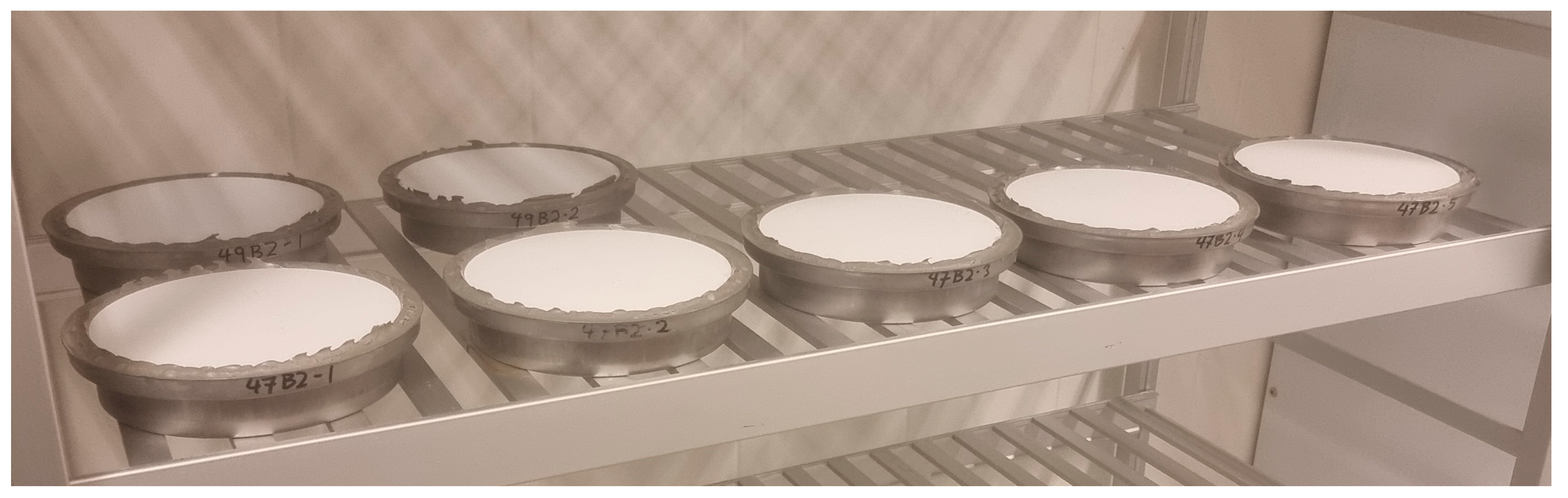
2.1.2. Preparation of Samples

One gypsum board was acquired for each type of paint and stored in a laboratory climate for about a week before sample preparation began. The gypsum boards were delineated into four equal segments, and each segment was painted with two layers of paint. The paint was evenly applied while the boards were lying flat with the painted surface up, indoors in a laboratory climate. The amount of paint applied per coat was in accordance with the manufacturers’ recommendations. The paint was allowed to dry for the time specified by the manufacturer, and for four hours at a minimum between each layer of paint. Two of the segments were then painted with two additional layers of paint. Finally, one of these segments was painted with two more layers. The samples were all painted by the same experienced laboratory technician using the same type of equipment, to ensure that the paint layers maintained thickness and cover as uniformly as possible.
After a minimum of one week, the plates were cut into four sections along the segment delineation lines: two sections with two layers of paint, one with four layers and one with six layers. One of the two-layer sections was set aside for spares in case additional samples were required. The three remaining sections were cut into six pieces each. A circular specimen with a diameter of 0.174 m was prepared from each piece using a circular vice and a band saw. Five such specimens were required to run a test, leaving one as a spare for each series. The unpainted gypsum board used for measurements was stored together with the painted samples.

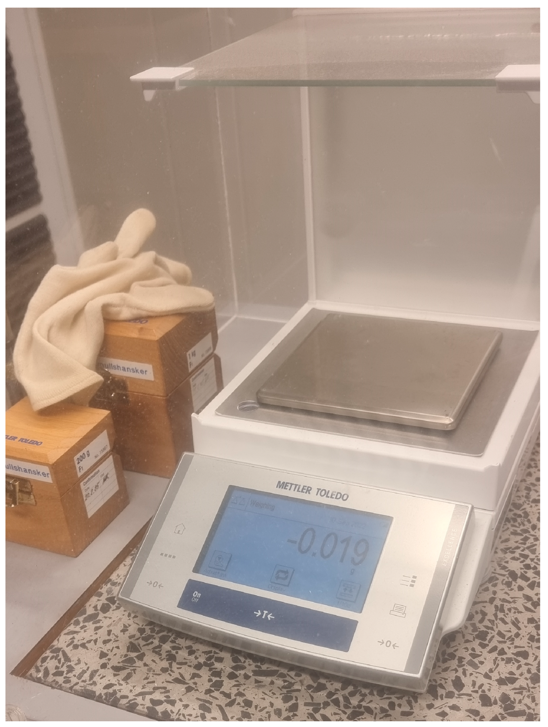
2.1.3. Test Procedure

The test procedure used to determine the water vapour resistance of the specimens was carried out as described in NS-EN ISO 12572:2016 [35]. The specimens were conditioned in a controlled climate chamber (23 ± 1 °C, RH 50 ± 5%) for 3–4 days before mounting in cups to create the test samples. Each sample consisted of a circular cup filled with a solution of potassium nitrite (KNO3), using the painted gypsum specimen as its sealed lid. The samples were stored and weighed in the controlled climate chamber until the end of the tests. A series of samples is portrayed in Figure 2.
The KNO3 solution ensured a constant RH of 94% [35] within the test sample cup. The evaporated salt solution diffused through the specimen, at a rate determined by the specimen’s water vapour permeability. The mass of the samples was weighed after initial preparation, and then at regular intervals. A reference weight of 1000 g was weighed before and after the samples to correct the output of the scale. The scale was a METTLER TOLEDO in the Excellence line, which measured at a resolution of 0.001 g and was accurate to within 0% at the time of weighing. The scale was kept within a plastic housing to protect from interference. Its accuracy is controlled annually by the Norwegian Metrology Service. The scale is pictured in Figure 3.
The interval of weighing depends on the expected water vapour permeability value and may be adjusted as the results begin to become apparent. For the present study, a weighing interval of once per day was selected and followed throughout the measurement period. The water vapour permeability is determined by the rate of change in weight over time. A stable rate of change is deemed to have been found if the change in weight over five consecutive weight measurements remains constant to within ±5% of their average rate of change [35].

2.2. WUFI Simulations

2.2.1. Geometry and Materials

The geometry of the modelled roof assembly, with monitor points for moisture assessment, is shown in Figure 4. This assembly is typical for the middle of a roof span, with mineral wool insulation placed within a frame structure made of 0.048 m wide wooden beams placed at a centre-to-centre distance of 0.6 m. A plywood board served as the roof underlay, covered with a bituminous roofing sheet. The SVB was mounted on the underside of the insulation layer. The ceiling was a gypsum board separated from the vapour barrier by a 0.023 m air cavity. The modelled geometry consisted of a cut-out of one 0.6 m wide section of the roof, centred around a wooden beam. Since this cut-out was symmetrical around the wooden beam, only one half of the section was modelled to save computing resources. Hence, the width of the simulated area is 0.3 m.

2.2.2. Simulation Input Data

The roof assembly was modelled using the hygrothermal simulation program WUFI® 2D by Fraunhofer IBP [36]. WUFI is an acronym of Wärme Und Feuchte Instationär—which, translated, means heat and moisture transiency. The material parameters used for the simulation are shown in Table 1. Material data were retrieved from the built-in WUFI material library, except the smart vapour barrier, whose data were found in the technical approval document [34], as conducted in a previous study by Storaas [17]. Table 2 shows the simulation input parameters. The simulation location of Kristiansund was chosen because its climate was previously found to be the most challenging for moisture safety in compact wooden roofs in Norway—if a solution is found not to present a mould risk there, it may be considered safe everywhere else too [17,37]. Oslo, as a comparison case, exhibits a warmer and drier climate. Rather high initial moisture values for the materials were chosen, to create a situation where the moisture safety of the assembly was dependent on the rate of drying. SINTEF generally recommends not to encapsulate a wooden structure whose moisture content is above 15 weight-% [38]. However, 20 weight-% is not an uncommonly high wood moisture level during the construction period. Using 20 weight-% illustrates the effects of drying to a greater degree. Likewise, a simulation start date in September is considered to elevate the mould growth risk, as the assembly is then considered to be encapsulated right at the beginning of the wetting season, and the longest possible amount of time elapses before drying begins. It may be considered a worst-case scenario for these moisture simulations.

2.3. WUFI Mould Index VTT

The WUFI plug-in WUFI Mould Index VTT [39] was used to assess the mould growth risk in the simulated assembly. This plug-in uses a mould growth model based on the work of Viitanen et al. [40,41,42,43]. The model describes mould growth based on the factors surface material, temperature, relative humidity (RH), and time. The predicted probability of mould growth activity is indicated on a scale from 0 to 6. The index is annotated as a “traffic light”, where a green label indicates an acceptably low risk of mould growth, a yellow label indicates that further investigation may be necessary, and a red label indicates unacceptable risks. For materials inside an assembly, not exposed to air, a Mould Index value of 2 is the threshold between the green and yellow label, while a value greater than 3 yields a red label. A Mould Index value greater than 3 may be physically interpreted to indicate visible mould growth [42].
The simulation parameter settings for the WUFI Mould Index VTT plug-in are listed in Table 3. The monitoring point for moisture in the upper part of the roof assembly, seen in Figure 4, was chosen because it is the most humid part of the assembly and thus represents the highest moisture risk [16,17]. Additional simulations were also conducted with a monitoring point on the back (unpainted) side of the gypsum board, to assess mould risk toward the interior side of the assembly.

3. Results

3.1. Laboratory Measurements

The measured sd values for the gypsum board with the six types of paint applied are shown in Table 4. The gypsum board itself had a declared sd value of 0.078 m in its product datasheet but was measured to be 0.071 m (the standard deviation of the mean was calculated to be 0.001 m). The latter figure was used in the simulations to simulate an unpainted ceiling.
Note that the water vapour resistance, as expressed through sd values, increased at a far-below-linear rate with multiple layers of paint for every product.

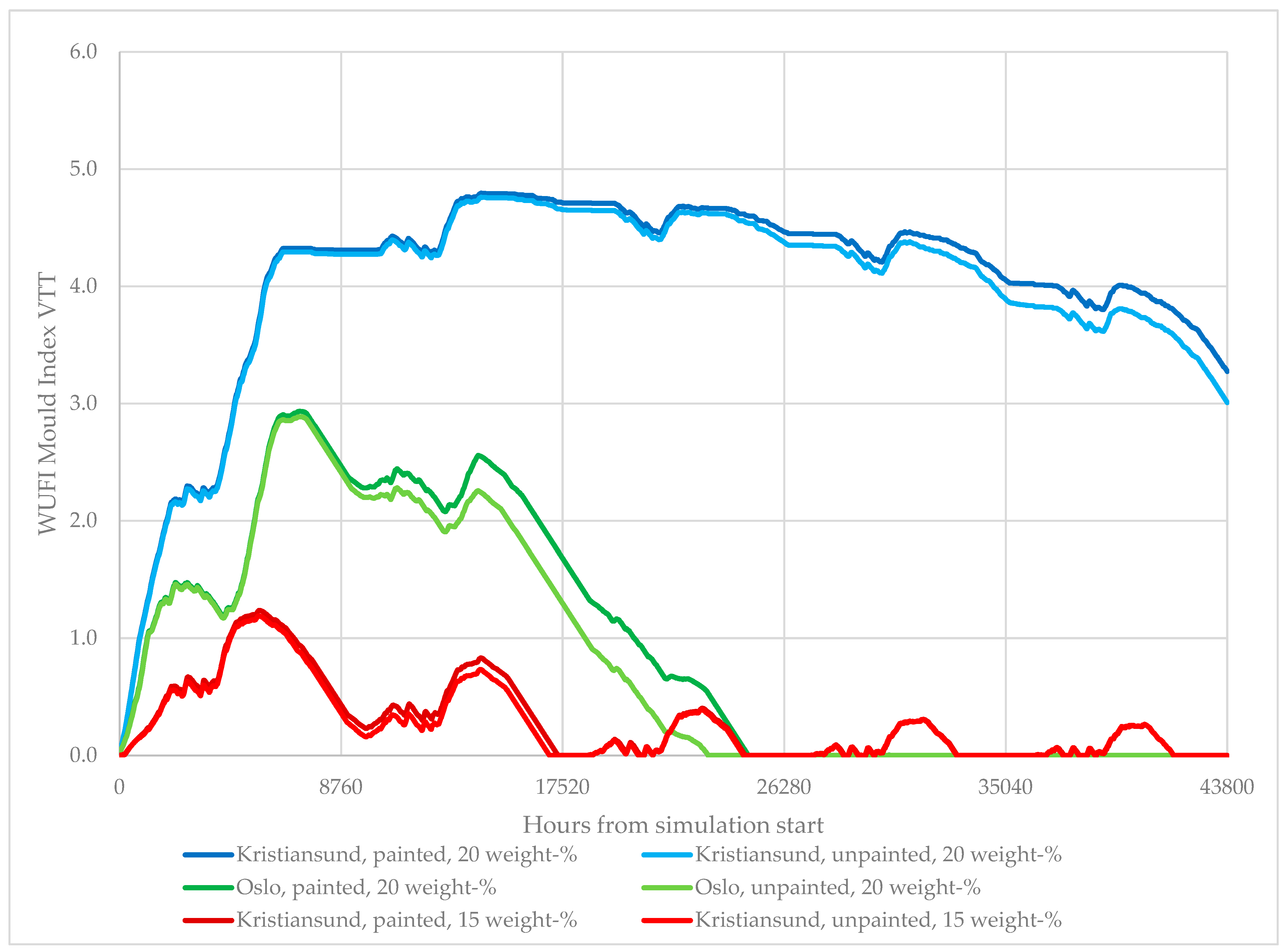
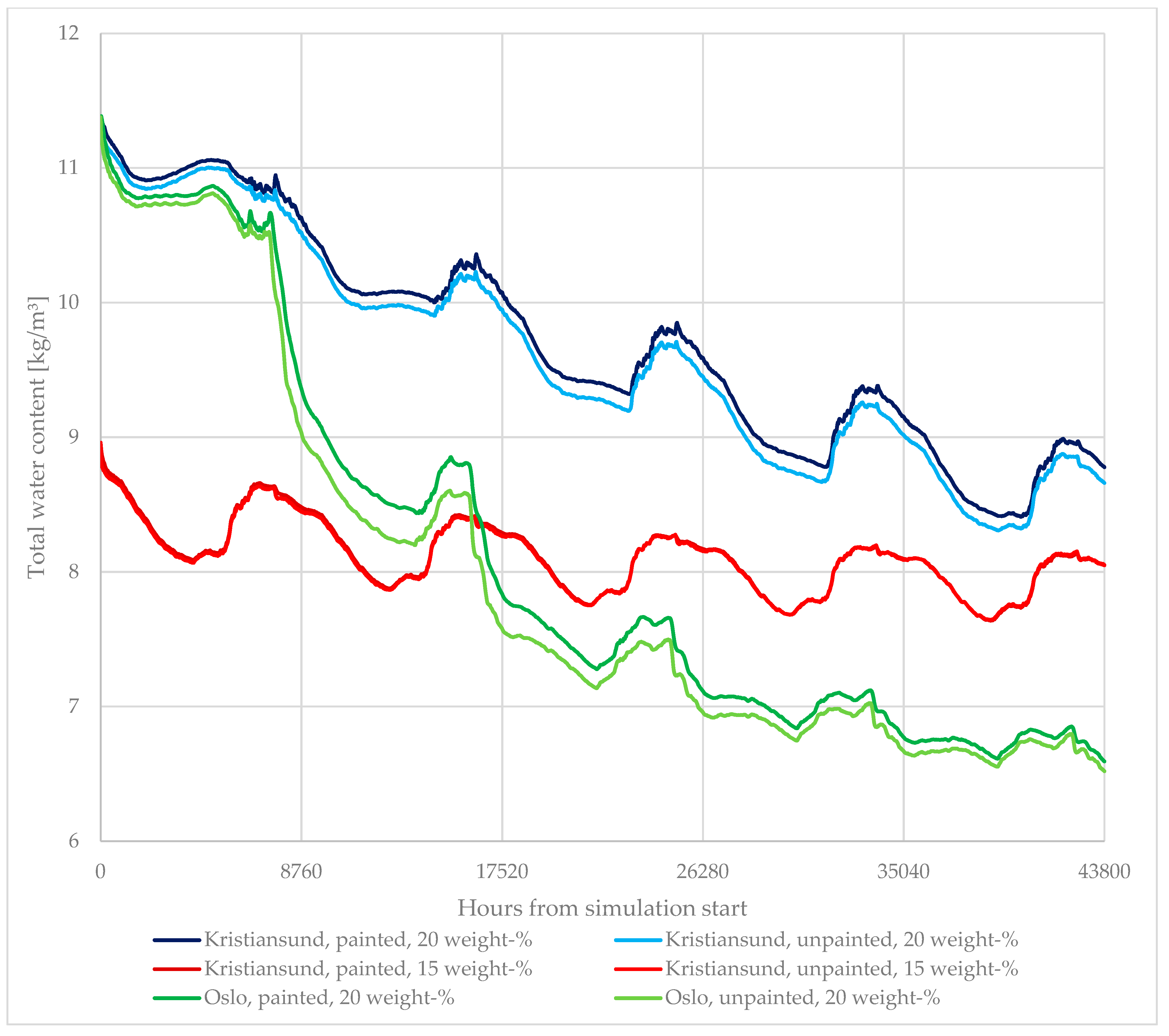
3.2. WUFI Simulations

Table 5 describes the variable configurations of each simulation case as well as the VTT Mould Index of each simulation scenario. The application of paint has little impact on the Mould Index. Rather, the initial moisture content of the structure is a much more significant risk factor for mould growth. For every simulation case, the Mould Index on the back side of the gypsum board was found to be 0.01 or lower.
Figure 5 shows the moisture performance of each simulation case as evaluated by using the WUFI Mould Index VTT. In the worst simulation case, the Mould Index rises in the first two years of simulation, because the structure is wetted during the first autumn and the built-in moisture does not dry sufficiently before the next wetting season. However, eventually, the structure dries out in every case, and conditions cease being favourable for mould growth. The effect of the ceiling paint makes very little difference to the overall Mould Index score of each simulation.
Figure 6 shows the moisture development of each simulation case as indicated by the total water content in the assembly over time. The importance of the local climate is evident, as the simulation case in Oslo dries out faster than the ones in Kristiansund and converges to a lower value.

4. Discussion

4.1. What Is the Range of Water Vapour Resistance for Common Ceiling Paints?

Laboratory measurements indicate that all the examined ceiling paints exhibited relatively low values of water vapour resistance. The sd values of the painted gypsum boards ranged from 0.1 to 0.5 m, depending on the number of layers of paint. This is comparable to the recommended sd value for wind barriers and breather membranes to facilitate drying to the exterior in ventilated cladding assemblies [20]. As indicated by the results in Section 3, the sd value of six layers with the least permeable paint was almost double that of the SVB when the roof was in a state of drying. The water vapour resistance did not increase linearly according to the number of layers. The added vapour resistance of each additional layer appeared to decrease with the number of layers. There was, however, some uncertainty related to the thickness of the paint coat, as this was not measured during testing. The samples were prepared from the middle of the gypsum boards, where the thickness of the board and paint was assumed to be more uniform than along the edges.
Note also that six layers of paint are not realistic for the ceiling of a newly built building. However, using these values helps to illustrate the impact of the ceiling paint to a greater degree, since repainting during the lifetime of the building will eventually add more layers of paint.

4.2. What Are the Implications of the Water Vapour Resistance of Ceiling Paints on the Drying Properties of Compact Wooden Roofs?

The impact of the water vapour resistance of ceiling paints on drying was shown to be comparably small. In practice, there was little difference between an unpainted gypsum board and one painted with six coats of the most vapour-tight paint in this study. Gypsum boards painted with common ceiling paints may be considered sufficiently vapour-open to effectively facilitate drying. Even the least vapour-open configuration did not substantially impact the water content of the simulated compact wooden roof assembly relative to the unpainted board, although the drying rate was lowered slightly. The initial water content of the assembly, and the local climate, were shown to impact the drying rate and mould growth to a vastly higher degree.
It may be interesting for future studies to evaluate the drying rate using even more vapour-tight ceiling assemblies. An earlier study of compact wooden roofs with SVBs simulated an internal water vapour resistance up to 1 m, indicating a difference large enough to warrant further study [16].
The present study investigated a generic case of a flat, black roof that received no shading. A shaded roof, one oriented away from the sun or a roof covered by a rooftop terrace deck, will receive less solar radiation and, hence, less heat. This will reduce inward moisture transport compared to the simulated case in the present study. In these cases, the impact of the ceiling paint may be greater. This also means that the design will be even more effective in climates outside of Norway, with greater solar radiation and, thus, increased moisture transportation.
The amount of built-in moisture was shown to impact the moisture performance of the roof to a substantial degree. The consequences of allowing an initial moisture content of 20 weight-% were substantial compared to 15%. Conversely, using a vapour-open ceiling assembly to facilitate drying did not compensate for failing to allow the materials to dry before encapsulating the assembly.
The impact of the building’s location is also substantial. A roof assembly in Oslo will experience vastly less mould growth and dry out almost three years earlier than an identical roof assembly in Kristiansund. These findings agree with earlier studies of drying and mould growth in roof assemblies in Norway [16,17,37].

5. Conclusions

The study indicates that gypsum boards painted with commonly available ceiling paints will exhibit sufficiently low water vapour resistance to facilitate effective drying to the interior side of a compact wooden roof with an SVB. The water vapour resistance of the ceiling assembly was found to be very low, regardless of which paint was used and up to six layers of paint. Other factors like built-in moisture or the exterior climate were found to influence the drying rate and mould growth risk to much greater degrees. These results may be used to create reference design guidelines for the use of SVBs in compact wooden roofs.
For future work, it may be interesting to study cases where the impact of ceiling paint may conceivably be greater, for instance in roofs that receive little heating from solar radiation and thus exhibit less inward drying. Future studies may also investigate the impact of ceiling assemblies with even higher water vapour resistance. Interesting materials for study may include pre-painted MDF boards, foil-coated particle boards, or paint intended for use in bathrooms. Other roof details and geometries should also be studied to evaluate the moisture performance of SVBs in compact wooden roofs under a wider range of conditions. Sufficient documentation of the performance is necessary to ensure that the solution can be adopted on an industry-wide scale.

Author Contributions

Conceptualization, T.K.; methodology, J.H.T., E.A. and T.K.; validation, J.H.T.; formal analysis, J.H.T.; investigation, J.H.T.; resources, T.K.; writing—original draft preparation, J.H.T. and E.A.; writing—review and editing, J.H.T., E.A. and T.K.; visualization, J.H.T.; supervision, E.A., S.G. and T.K.; project administration, T.K.; funding acquisition, T.K. All authors have read and agreed to the published version of the manuscript.

Funding

This research was funded by The Research Council of Norway, grant number 237859.

Data Availability Statement

Supporting reported results will be made available at ntnuopen.ntnu.no three months after censorship of the M.Sc thesis of Jørgen Haldorsen Tomren.

Acknowledgments

This research was carried out as part of the research project SFI Klima 2050. The authors would like to extend thanks to laboratory engineer Ole Aunrønning.

Conflicts of Interest

The authors declare no conflict of interest. The funders had no role in the design of the study; in the collection, analyses, or interpretation of data; in the writing of the manuscript; or in the decision to publish the results.

References

  1. Noreng, K. Kompakte Tak; Byggforskserien 525.207; SINTEF: Oslo, Norway, 2018. [Google Scholar]
  2. Viitanen, H.; Vinha, J.; Salminen, K.; Ojanen, T.; Peuhkuri, R.; Paajanen, L.; Lähdesmäki, K. Moisture and Bio-Deterioration Risk of Building Materials and Structures. J. Build. Phys. 2010, 33, 201–224. [Google Scholar] [CrossRef]
  3. Viitanen, H. Factors Affecting the Development of Biodeterioration in Wooden Constructions. Mater. Struct. 1994, 27, 483–493. [Google Scholar] [CrossRef]
  4. Brischke, C.; Bayerbach, R.; Otto Rapp, A. Decay-Influencing Factors: A Basis for Service Life Prediction of Wood and Wood-Based Products. Wood Mater. Sci. Eng. 2006, 1, 91–107. [Google Scholar]
  5. Jaakkola, M.S.; Jaakkola, J.J.K. Indoor Molds and Asthma in Adults. In Advances in Applied Microbiology; Academic Press: Cambridge, MA, USA, 2004; Volume 55, pp. 309–338. [Google Scholar]
  6. Becher, R.; Høie, A.H.; Bakke, J.V.; Holøs, S.B.; Øvrevik, J. Dampness and Moisture Problems in Norwegian Homes. Int. J. Environ. Res. Public Health 2017, 14, 1241. [Google Scholar] [CrossRef]
  7. Gradeci, K.; Berardi, U. Application of Probabilistic Approaches to the Performance Evaluation of Building Envelopes to Withstand Mould Growth. J. Build. Phys. 2019, 43, 187–207. [Google Scholar] [CrossRef]
  8. Bunkholt, N.S.; Gullbrekken, L.; Geving, S.; Kvande, T. Compact Wooden Roofs with Smart Vapour Barrier–Pilot Project Experiences. E3S Web Conf. 2020, 172, 07010. [Google Scholar] [CrossRef]
  9. Geving, S.; Thue, J.V. Fukt i Bygninger; Håndbok 50; Norsk Byggforskningsinstitutt: Oslo, Norway, 2002. [Google Scholar]
  10. Bøhlerengen, T. Fukt i Bygninger. Teorigrunnlag; Byggforskserien 421.132; SINTEF: Oslo, Norway, 2018. [Google Scholar]
  11. Bunkholt, N.S.; Gullbrekken, L.; Time, B.; Kvande, T. Pitched Unventilated Wood Frame Roof with Smart Vapour Barrier–Field Measurements. J. Phys. Conf. Ser. 2021, 2069, 012007. [Google Scholar] [CrossRef]
  12. Kvande, T.; Gullbrekken, L.; Geving, S. Pilotprosjekt|Smart Dampsperre Longyearbyen Boliger, Statsbygg. Premisser og Trefuktmåling; Klima 2050 Note 58; SINTEF: Trondheim, Norway, 2018. [Google Scholar]
  13. Gullbrekken, L.; Kvande, T. Pilotprosjekt|Smart Dampsperre Sveabakken, Norgeshus. Premisser og Trefuktmåling; Klima 2050 Note 56; SINTEF: Trondheim, Norway, 2018. [Google Scholar]
  14. Geving, S.; Olsen, T.-A. Compact Wooden Roofs with Smart Vapour Barriers–Effect of Wooden Joists on Drying of Built-in Moisture. MATEC Web Conf. 2019, 282, 02009. [Google Scholar] [CrossRef]
  15. Geving, S.; Stellander, M.; Uvsløkk, S. Smart Vapour Barriers in Compact Wood Frame Roofs. In Proceedings of the Thermal Performance of the Exterior Envelopes of Whole Buildings XII International Conference, Clearwater, FL, USA, 1–5 December 2013. [Google Scholar]
  16. Sletfjerding, E.B. Smart Vapour Barriers in Compact Timber-Framed Roofs: Parameter Analysis and Field Measurements. Master’s Thesis, Norwegian University of Science and Technology, Trondheim, Norway, 2019. [Google Scholar]
  17. Storaas, K. Smart Dampsperre i Kompakte Tretak-Vurdering av Fuktsikkerhet. Master’s Thesis, Norwegian University of Science and Technology, Trondheim, Norway, 2020. [Google Scholar]
  18. Kuenzel, H.M. The Smart Vapor Retarder: An Innovation Inspired by Computer Simulations. In ASHRAE Annual Meeting; ASHRAE Transactions: Toronto, ON, Canada, 1998; pp. 903–907. [Google Scholar]
  19. Johnsen, I.-H.; Andenæs, E.; Gullbrekken, L.; Kvande, T. Vapour Resistance of Wind Barrier Tape: Laboratory Measurements and Hygrothermal Performance Implications. J. Build. Phys. 2022, 46, 923–940. [Google Scholar] [CrossRef]
  20. Einstabland, H. Undertak; Byggforskserien 525.866; SINTEF: Oslo, Norway, 2009. [Google Scholar]
  21. Uvsløkk, S. Materialer Til Luft-Og Damptetting; Byggforskserien 573.121; SINTEF: Oslo, Norway, 2003. [Google Scholar]
  22. Geving, S.; Holme, J. Vapour Retarders in Wood Frame Walls and Their Effect on the Drying Capability. Front. Archit. Res. 2013, 2, 42–49. [Google Scholar] [CrossRef]
  23. Tariku, F.; Maref, W.; Di Leonardo, B.; Gatland, S. Hygrothermal Performance of RH-Dependent Vapour Retarder in Canadian Coastal Climate. In Proceedings of the 12th Canadian Conference of Building Science and Technology, Montreal, QC, Canada, 6 May 2009. [Google Scholar]
  24. Yoshinaga, M. Performance of Smart Vapor Retarders under Hot and Humid Summer Conditions. Build. Environ. 2022, 218, 109163. [Google Scholar] [CrossRef]
  25. Fechner, H.; Meißner, F. Advanced Modelling of Vapor Resistance of Moisture Dependent Vapor Retarder. Energy Procedia 2017, 132, 201–206. [Google Scholar] [CrossRef]
  26. Eckhaus, S.; Wolock, I.; Harris, B.L. Porosity of Paint Films. Water Vapor Adsorption and Permeability. Ind. Eng. Chem. 1953, 45, 426–428. [Google Scholar] [CrossRef]
  27. Thun, E.; Øvregaard, A. Malingfilmers Permeabilitet for Vanndamp; Norges Byggforskningsinstitutt: Trondheim, Norway, 1961. [Google Scholar]
  28. Huldén, M.; Hansen, C.M. Water Permeation in Coatings. Prog. Org. Coat. 1985, 13, 171–194. [Google Scholar] [CrossRef]
  29. Topçuoğlu, Ö.; Altinkaya, S.A.; Balköse, D. Characterization of Waterborne Acrylic Based Paint Films and Measurement of Their Water Vapor Permeabilities. Prog. Org. Coat. 2006, 56, 269–278. [Google Scholar] [CrossRef]
  30. Šadauskienė, J.; Monstvilas, E.; Stankevičius, V. The Impact of Exterior Finish Vapour Resistance on the Moisture State of Building Walls. Technol. Econ. Dev. Econ. 2007, 13, 73–82. [Google Scholar] [CrossRef]
  31. Brito, V.; Gonçalves, T.D.; Faria, P. Coatings Applied on Damp Building Substrates: Performance and Influence on Moisture Transport. J. Coat. Technol. Res. 2011, 8, 513–525. [Google Scholar] [CrossRef]
  32. Nicodemo, L.; Bellucci, F.; Marcone, A.; Monetta, T. Water and Oxygen Transport as Performance Parameters of Paint Films. J. Membr. Sci. 1990, 52, 393–403. [Google Scholar] [CrossRef]
  33. Hoseinpoor, M.; Prošek, T.; Mallégol, J. Novel Approach to Measure Water Vapor Permeability in Pre-Painted Metals Using Adapted Cup Method: Correlation between Permeation Rate and Tendency to Blistering. Prog. Org. Coat. 2022, 169, 106917. [Google Scholar] [CrossRef]
  34. SINTEF Certification TG 20321|Isola AirGuard® Smart2 Fuktadaptiv Dampsperre; SINTEF Certification: Oslo, Norway, 2022.
  35. NS-EN ISO 12572:2016; ISO Hygrothermal Performance of Building Materials and Products-Determination of Water Vapour Transmission Properties-Cup Method (ISO 12572:2016). Norsk Standard: Oslo, Norway, 2016.
  36. Fraunhofer IBP WUFI® 2D. Available online: https://wufi.de/en/software/wufi-2d/ (accessed on 17 August 2023).
  37. Fuglestad, F.E.; Andenæs, E.; Geving, S.; Kvande, T. Determining the Vapour Resistance of Breather Membrane Adhesive Joints. Materials 2022, 15, 6619. [Google Scholar] [CrossRef]
  38. Bøhlerengen, T.; Thommesen, J.E. Fuktsikkerhet. Viktige Kontrollpunkter Ved Prosjektering Og Utførelse; Byggforskserien 474.511; SINTEF: Oslo, Norway, 2021. [Google Scholar]
  39. Fraunhofer IBP WUFI Mould Index VTT. Available online: https://wufi.de/en/2017/03/31/wufi-mould-index-vtt/ (accessed on 17 August 2023).
  40. Hukka, A.; Viitanen, H.A. A Mathematical Model of Mould Growth on Wooden Material. Wood Sci. Technol. 1999, 33, 475–485. [Google Scholar] [CrossRef]
  41. Viitanen, H.; Bjurman, J. Mould Growth on Wood under Fluctuating Humidity Conditions. Mater. Und Org. 1995, 29, 27–46. [Google Scholar]
  42. Viitanen, H.; Ritschkoff, A.-C. Mould Growth in Pine and Spruce Sapwood in Relation to Air Humidity and Temperature; Swedish University of Agricultural Sciences, Department of Forest Products: Uppsala, Sweeden, 1991. [Google Scholar]
  43. Viitanen, H.; Ojanen, T. Improved Model to Predict Mould Growth in Building Materials. In Proceedings of the the 10th Thermal Performance of the Exterior Envelopes of Whole Buildings Conference, Clearwater, FL, USA, 2 December 2007. [Google Scholar]
Figure 1. The working principle of an SVB in a compact wooden roof.
Buildings 13 02185 g001
Figure 2. Samples of painted gypsum board, stored on shelves in a controlled climate chamber.
Buildings 13 02185 g002
Figure 3. The scale used for measurements.
Buildings 13 02185 g003
Figure 4. Roof geometry simulated using WUFI 2D, schematic (left) and WUFI geometry (right). Monitor point for moisture assessment shown in blue (upper and lower right corners).
Buildings 13 02185 g004
Figure 5. Development of the VTT Mould Growth Index (see Section 2.3) for the six simulation cases. The vertical grid lines are spaced one year apart.
Buildings 13 02185 g005
Figure 6. Total water content in the assembly for each of the six simulation cases.
Buildings 13 02185 g006
Table 1. Material properties for the WUFI 2D simulations. The sd value is given for the direction of drying, vertically.
MaterialsDensity [kg/m3]Thermal Conductivity [W/(mK)]sd Value
[m]
Roofing7152.3300
Plywood4100.133.78
Wood (Scandinavian spruce transverse
direction II)
3900.1338
Mineral wool600.0400.45
Smart vapour barrier852.40.25–12.8
(See Table 3 in [34])
Air cavity1.30.160.012
Gypsum board8500.20.071
Table 2. Input parameters for the simulations in WUFI 2D.
WUFI 2D SettingsStandard ParametersVariations
Numerical gridMode XCoarse
Mode YMedium
Exterior climateKristiansundOslo
Initial moistureWood20 weight-%15 weight-%
Mineral wool80% RH
Gypsum board80% RH
Bitumen roofing80% RH
Air cavity80% RH
Smart vapour
barrier
80% RH
Gypsum board sd value0.071 m *0.533 m **
Distance between beams0.6 m
Roof slope
Short-wave radiation absorptivity0.88
Interior temperature23 °C
Interior moisture supplyHumidity Class 2
Simulation begins2022-09-01
Duration of simulation43,800 h (five years)
* Equivalent to that of an unpainted gypsum board, see Section 3.1. ** Equivalent to the highest measured sd value in the laboratory tests.
Table 3. WUFI Mould Index parameter settings.
ParameterSetting
Sensitivity classSensitive
Material classRelevant decline
Type of surfacePlaned
Type of woodSoftwood
Occupant exposition classSurfaces inside constructions without direct contact with indoor air
Table 4. Measured sd values [m] for the different samples (including gypsum board), by number of layers. The standard deviation of the mean for each measurement series is shown in brackets.
ProductTwo LayersFour LayersSix Layers
A0.29 (0.003)0.44 (0.006)0.53 (0.007)
B0.093 (0.001)0.12 (0.001)0.14 (0.001)
C0.32 (0.009)0.43 (0.008)0.52 (0.005)
D0.074 (0.001)0.087 (0.000)0.091 (0.001)
E0.16 (0.002)0.27 (0.007)0.36 (0.007)
F0.18 (0.002)0.28 (0.004)0.36 (0.003)
Table 5. Description of the six simulation cases and the VTT Mould Index results for each case. The simulation variables are otherwise as listed in Table 2.
Simulation Case
Variable 123456
LocationKristiansundXXXX
Oslo XX
CeilingUnpaintedX X X
Painted X X X
Initial wood moisture content20%XX XX
15% XX
Mould Index4.764.801.191.242.892.93
Disclaimer/Publisher’s Note: The statements, opinions and data contained in all publications are solely those of the individual author(s) and contributor(s) and not of MDPI and/or the editor(s). MDPI and/or the editor(s) disclaim responsibility for any injury to people or property resulting from any ideas, methods, instructions or products referred to in the content.

