Article

Exergy Analysis of Transcritical CO2 Air-Source Heat Pump with Honeycomb Gas Cooler

1
School of Human Settlements and Civil Engineering, Xi’an Jiaotong University, Xi’an 710049, China
2
College of Energy Engineering, Xi’an University of Science and Technology, Xi’an 710054, China
3
Sustainable Buildings Research Centre (SBRC), University of Wollongong, Wollongong, NSW 2522, Australia
*
Author to whom correspondence should be addressed.
Buildings 2023, 13(9), 2147; https://doi.org/10.3390/buildings13092147
Submission received: 3 July 2023 / Revised: 20 August 2023 / Accepted: 22 August 2023 / Published: 24 August 2023

Abstract

:
In order to build an efficient and energy-saving CO2 heat pump system and to improve the heat transfer efficiency of the gas cooler, a novel honeycomb gas cooler with a compact structure, high heat transfer efficiency, and high pressure-bearing capacity was proposed in our previous work. To clarify the components in the system that need further optimization and to improve its performance, an exergy analysis of a transcritical CO2 air-source heat pump system with the novel honeycomb gas cooler is studied in this paper. Based on the second law of thermodynamics, the exergy model of each component in the heat pump system is established, and the irreversible loss of each component is analyzed. In addition, the degree of energy loss of the honeycomb gas cooler is clarified, and the possibility and direction of system optimization are pointed out. The results show that the exergy efficiency of the system is 35.33% under nominal operating conditions, and there is a lot of room for improvement in its energy utilization. The three components with the largest exergy destruction percentage are the compressor, throttle valve, and evaporator in the order of 36.13%, 22.90%, and 19.51%, respectively. These components with high exergy destruction percentages are the main reasons for the large irreversible losses of the system.

1. Introduction

Energy is not only the basic driving force of social development and an important support for the modern economy but is also a leading factor in the progress of human civilization. With accelerated industrialization, energy crisis and environmental problems are becoming more and more prominent, which have become an important limitation to economic development. Therefore, exploring and optimizing the efficient utilization of energy technology has become a hot spot for research in various countries [1]. Nowadays, abundant nonfossil energy resources, especially renewable energy resources, have become an important part of energy resource endowment [2]. The development potential of wind, solar, and air energy remains huge. Promoting energy transformation and increasing renewable energy development and utilization is conducive to providing abundant kinetic energy to promote green and low-carbon development [3].
One of the applications of air energy is the air-source heat pump (Carnot cycle), which can realize the use of evaporators to absorb low-grade heat energy from the air, which is converted into high-grade heat energy through the compressor compression and condenser condensation processes, and which is then applied to different heat-using situations. Its thermal efficiency is greater than one and can reach more than three when used for the production of low-grade hot water [4]. Natural refrigerants that are not harmful to nature have become a very promising choice for heat pumps. Carbon dioxide (CO2) is considered an ideal refrigerant for heat pump water heaters because of its superior environmental friendliness; excellent thermodynamic properties; and safety properties, such as nonflammability, nontoxicity, and chemical stability [5,6,7,8,9,10].
In order to improve and evaluate the energy efficiency of the transcritical CO2 heat pump, the method of exergy analysis has become the focus and topicality of current research [11,12,13]. The exergy analysis method is based on the second law of thermodynamics; the method cannot only clarify the energy conversion efficiency and the degree of effective energy utilization and analyze whether the degree of energy utilization is reasonable, but it can also clarify the size and location distribution of the irreversible losses in the system and propose ways to improve and predict the effect of optimized energy utilization [14,15]. The exergy analysis method has been applied by many scholars in different system studies due to its superiority in analyzing the effectiveness of energy utilization [16,17,18].
Liu et al. [19] divided the total exergy destruction of heat exchanger components into dissipative exergy destruction and thermal exergy destruction, and the ratio of total exergy destruction to thermal exergy destruction was defined as the temperature matching degree. On this basis, a method for evaluating the effect on the thermal performance of heat pump systems in complex heat transfer processes at nonlinear sliding temperatures was proposed. Maddah et al. [20] investigated the heating and cooling modes of a CO2 heat pump cycle at different ambient temperatures and gas cooler CO2 outlet temperatures. The COP and exergy efficiencies were (2.762, 0.293) and (2.395, 0.292) at the ambient temperature of 0 °C and the gas cooler CO2 outlet temperatures of 30 °C and 35 °C, respectively. Wang et al. [21] performed an energy analysis, exergy analysis, and exergy economic analysis on a transcritical CO2 heat pump with/without an internal heat exchanger (IHX). They indicated that increasing the efficiency of the IHX was beneficial for improving the system performance factor, the irreversible losses of the throttle valve were reduced by 40.36~50.73%, and the total system irreversible losses were reduced by 2.74~8.24%. Ghazizade et al. [22] analyzed in depth the effect of the expander and the IHX on the exergy efficiency. They showed that the use of an IHX in a CO2 transcritical cycle with an expansion valve always leads to an increase in the system COP and exergy efficiencies. However, the use of an IHX in a CO2 transcritical cycle with an expander has a smaller effect on the COP and exergy efficiencies. Wang et al. [23] studied a CO2/R32 refrigerant blend for a transcritical CO2 heat pump and determined that the optimum concentration of the CO2/R32 blend was 0.9/0.1. The increase in the COP and exergy efficiencies was more significant in cold climates. Zhang et al. [24] proposed a novel dual heat-source compression/injection transcritical CO2 heat pump system and compared its performance with a conventional one. It was found that the maximum exergy destruction of the new system at 20 Hz~30 Hz occurred in the gas cooler, while the maximum exergy destruction at 35 Hz was in the compressor.
To solve the problems of the large irreversible losses of the gas cooler and the poor control of the optimal discharge pressure of the system, which still exist in the practical application of the transcritical CO2 heat pump, and to improve its performance, the authors’ team [25,26,27] proposed a honeycomb heat exchanger based on the biomimetic principle that can effectively take advantage of the microchannel heat exchanger with a compact structure, high heat transfer efficiency, and high pressure-bearing capacity. In previous studies, the flow and heat transfer characteristics of supercritical CO2 in a honeycomb heat exchanger were mainly investigated and compared with a printed circuit heat exchanger. The results showed that the heat transfer coefficient of the biomimetic honeycomb fractal heat exchanger was improved by 144.6% compared to the printed circuit heat exchanger.
Meanwhile, this novel honeycomb gas cooler is applied to a transcritical CO2 air-source heat pump system, and in order to clarify the components in the system that need further optimization and improvement, it is necessary to conduct an exergy analysis study. Based on the second law of thermodynamics, this paper establishes the exergy model of each component in the heat pump system, analyzes the magnitude of the irreversible losses of each component, clarifies the degree of energy loss of the honeycomb gas cooler, summarizes the effects of an ambient temperature and of inlet and outlet water temperature changes on the exergy destruction of the components, and points out the possibility and direction of system optimization. The research results of this paper can promote the popularization and application of the transcritical CO2 heat pump and can help to reduce the energy consumption of buildings to save energy and reduce carbon emissions.

2. Model of CO2 Heat Pump System

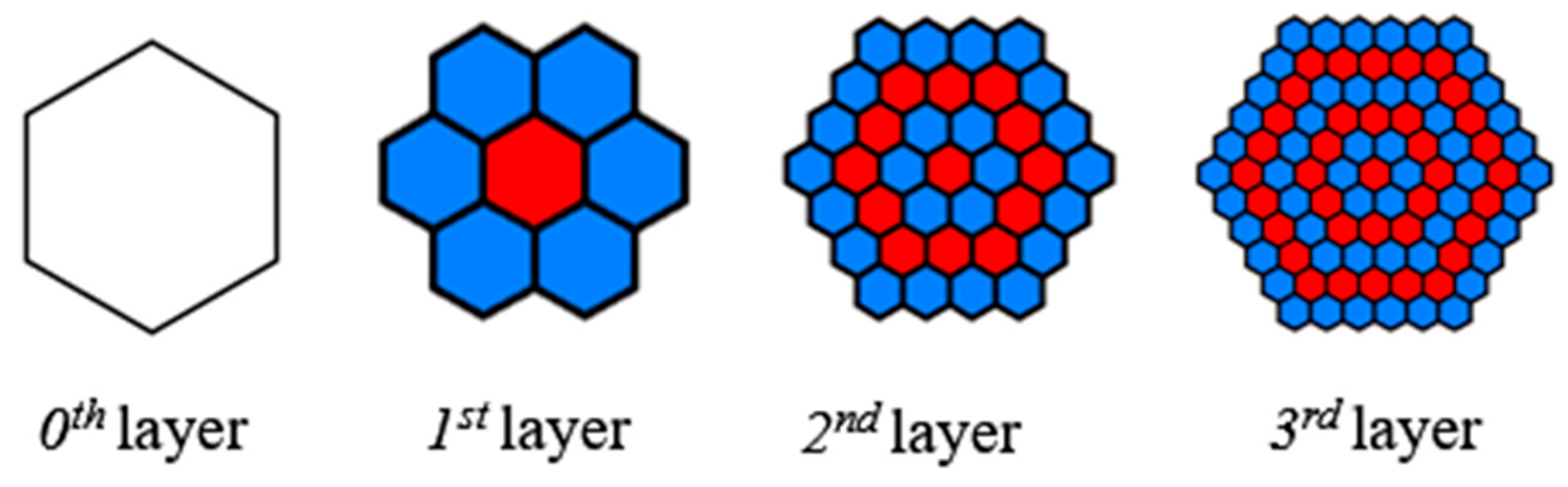
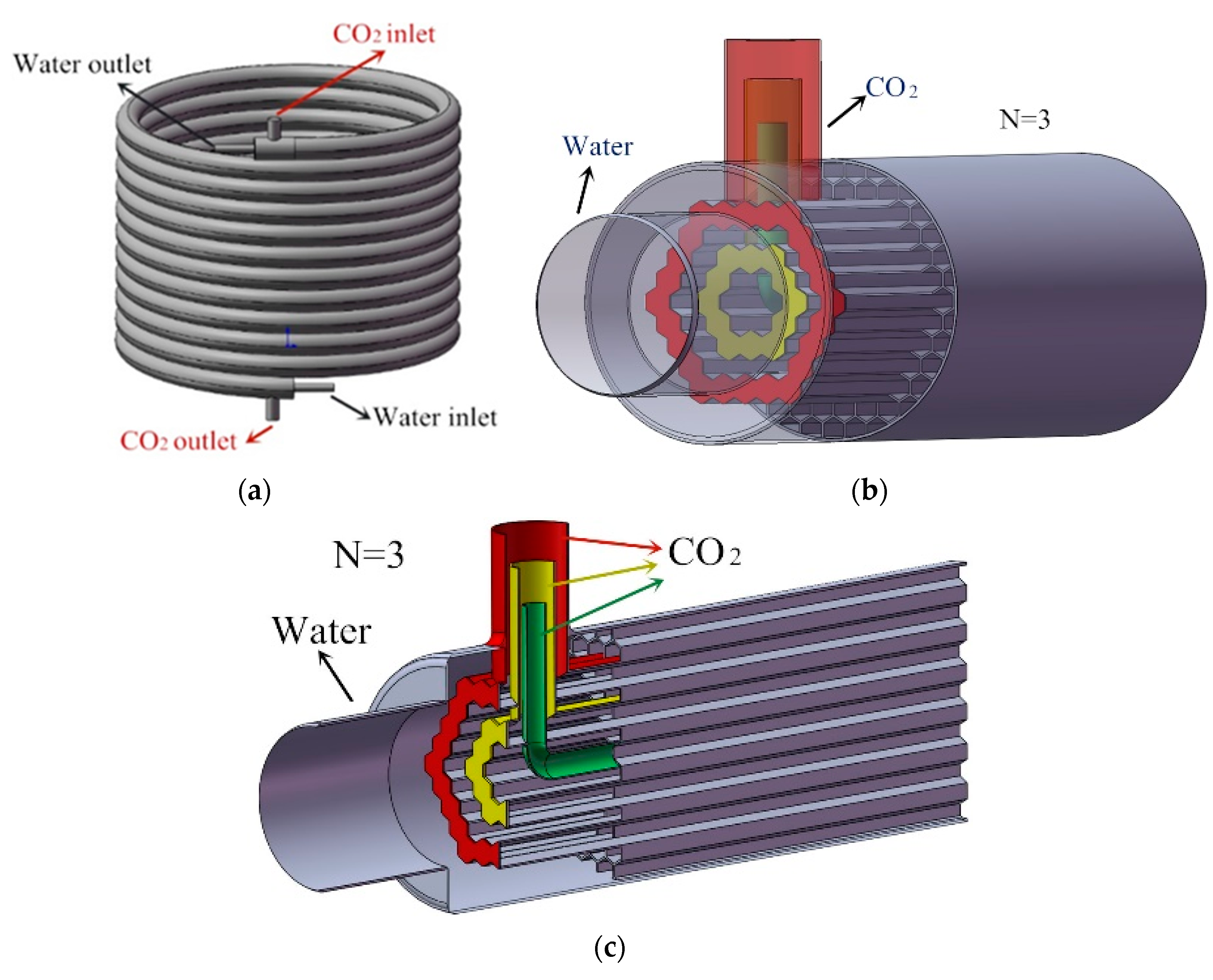
2.1. Introduction of Biomimetic Honeycomb Gas Cooler

To improve the heat transfer efficiency of the gas cooler and the performance of the heat pump, the authors’ team proposed a honeycomb gas cooler. Figure 1 shows the cross-sectional schematic of the honeycomb gas cooler’s different honeycomb layers. Figure 2 shows the physical model structure of the honeycomb gas cooler with three layers as an example. The physical characteristics and mathematical model of this type of gas cooler are shown in the literature [24] and have the following advantages:
  • Each hexagonal unit of this honeycomb structure uses the walls of its surrounding units as its own heat transfer ribs, increasing the heat transfer area, and the monolithic honeycomb plays an intensive effect, enhancing the heat transfer capacity of individual units and significantly improving the heat transfer effect of the whole heat exchanger.
  • The structure makes the hot and cold fluids in the heat exchange in reverse cross-cut not only to facilitate heat transfer but also to have a self-scouring effect to prevent fluid scaling in the heat exchanger wall.
  • The honeycomb unit can make the cross-sectional flow velocity in the direction of fluid flow converge while driving the cross-sectional temperature gradient to tend to be uniform with the ideal field synergy effect, improving the efficiency of heat transfer.
  • The honeycomb structure has strong pressure-bearing capacity and has the characteristics of periodic topological distribution. Honeycomb can absorb the energy of load action through the bending deformation of the cell wall with excellent stiffness, strength, and energy absorption performance.
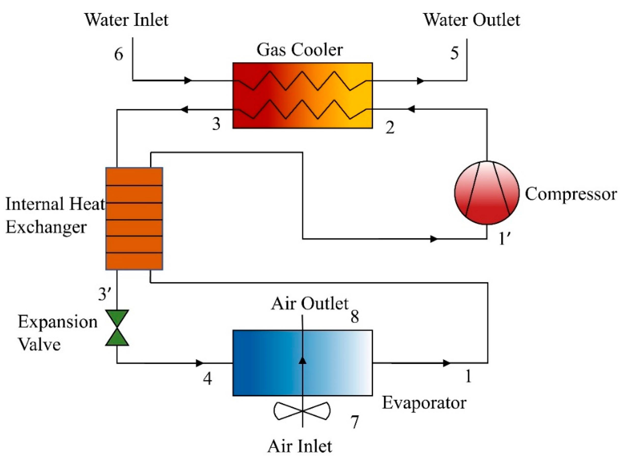
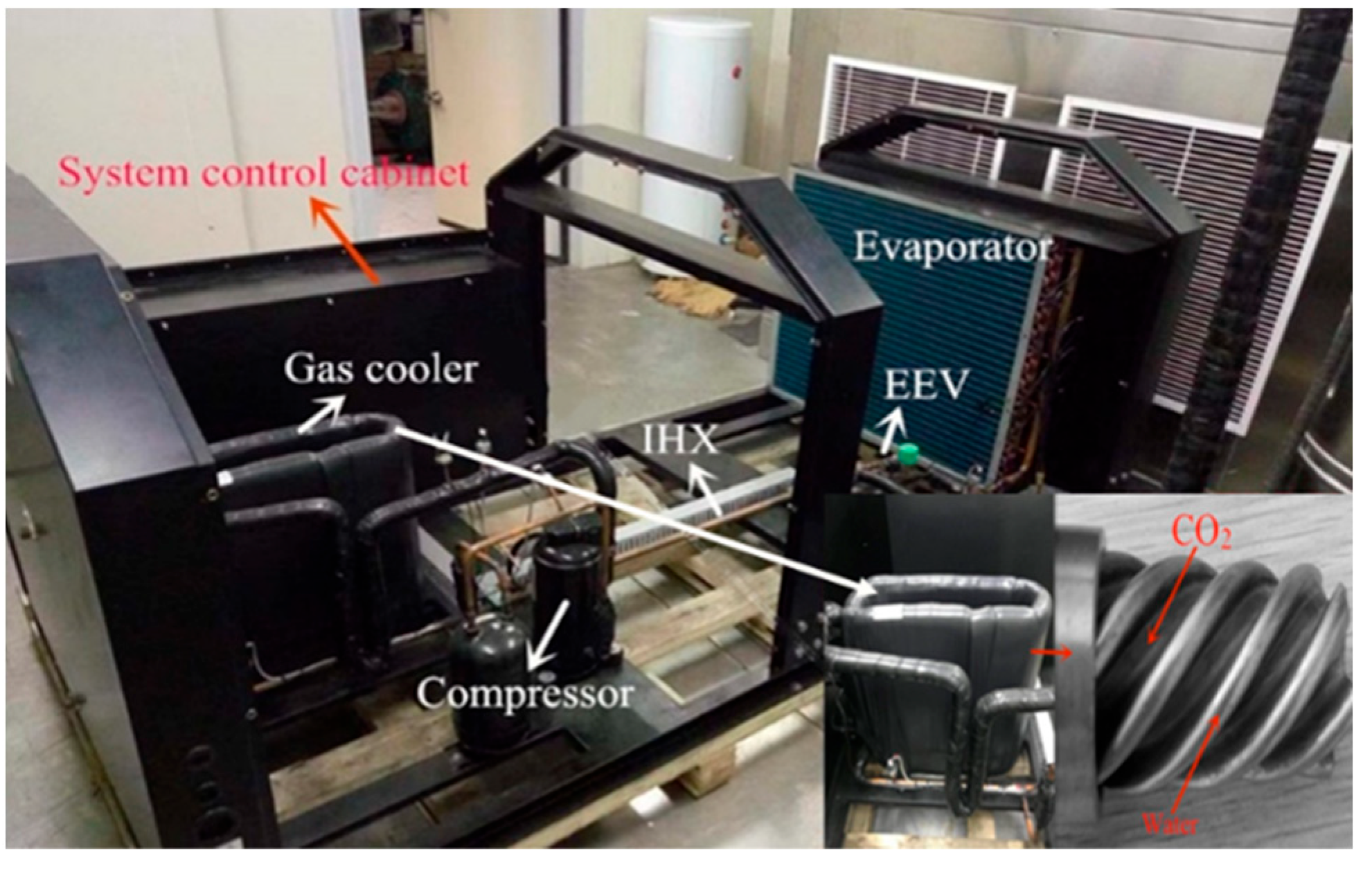
2.2. System Model

As shown in Figure 3, the transcritical CO2 air-source heat pump cycle studied in this paper consisted of five main components: compressor, honeycomb gas cooler, evaporator, expansion valve, and IHX. The transcritical CO2 air-source heat pump cycle with IHX consisted of the following five processes:
  • Compression process 1′–2: low-temperature and low-pressure CO2 was compressed to high-temperature and high-pressure state; in this process, due to the compressor’s unequal entropy compression, the actual outlet temperature of the compressor was greater than the temperature of equal entropy compression.
  • Cooling process 2–3: CO2 was cooled from high-temperature and high-pressure state to low-temperature and high-pressure state in the gas cooler.
  • Internal heat exchange processes 3–3′ and 1–1′: the CO2 from the gas cooler and the CO2 from the evaporator heat exchanged and were used to reduce the CO2 temperature at the throttle valve inlet and to increase the CO2 temperature at compressor suction.
  • Throttling process 3′–4: CO2 in a high-pressure state moved through the throttle valve, throttling into low-pressure two-phase state.
  • Evaporation process 4–1: the two-phase CO2 evaporated in the evaporator and became saturated or superheated.
The mathematical models of all components are described in turn below.
Compressor:
m r = ρ 1 V c o m
where mr is mass flow rate of CO2 in kg·s−1, ρ1′ is density at the inlet of the compressor in kg·m−3, and Vcom is the actual compressor gas delivery volume in m3·r−1.
h 2 = h 1 + h 2 , i s h 1 η i s
where h1′ is compressor inlet enthalpy in J·kg−1, h2 is actual enthalpy of compressor outlet in J·kg−1, h2,is is isentropic compression with respect to the compressor outlet enthalpy in J·kg−1, and ηis is isentropic efficiency.
a = 1
where W is compressor power consumption in kW.
Honeycomb gas cooler [27]:
Q j = m w , j c p , w ( t w o u t , j t w i n , j )
Q j = m r , j [ h r i n , j h r o u t , j ]
L M T D j = ( t r i n , j t w o u t , j ) ( t r o u t , j t w i n , j ) ln ( t r i n , j t w o u t , j t r o u t , j t w i n , j )
Q j = L M T D j 1 h r , j A r , j + δ λ w a l l A r , j + 1 h w , j A w , j
where Q is the heat transfer capacity in W, m is the mass flow rate in kg/s, cp,w is the specific heat capacity of water in J/kg·K, t is the temperature in K, h(t,p) is the enthalpy in J/kg, h is the heat transfer coefficient in W/(m2·K), Aw,j is the heat exchange area in (6 + 24(n2 − n))aL m2, δ is the wall thickness in m, and λwall is the thermal conductivity of the wall. In this study, the material of the tube is copper with 398 W/(m2·K).
Evaporator:
Q e , r = m r ( h r , i n h r , o u t ) = α r A i ( T w a l l T r , i n + T r , o u t 2 )
where Qe,r is heat transfer capacity of refrigerant side in W, hr,in is inlet enthalpy of evaporator microelement section in J·kg−1, αr is refrigerant-side heat transfer coefficient in W·(m2·K)−1, hr,out is evaporator microelement section outlet enthalpy in J·kg−1, Ai is evaporator microelement section in-tube heat transfer area in m2, Twall is evaporator wall temperature in °C, Tr,in is inlet temperature of evaporator microelement section in °C, and Tr,out is outlet temperature of evaporator microelement section in °C.
Q e , a = m a ( h a , i n h a , o u t ) = ξ α a A o ( T a , i n + T a , o u t 2 T wall )
where Qe,a is heat transfer capacity of air side in W, ma is air mass flow rate in kg∙s−1, ha,in is air inlet enthalpy of the evaporator microelement section in J·kg−1, αa is air-side heat transfer coefficient in W·(m2·K)−1, ha,out is air outlet enthalpy of evaporator microelement section in J·kg−1, Ao is heat transfer area outside the tube of evaporator microelement section in m2, and ξ is coefficient of moisture analysis.
Q e , a = Q e , r
Expansion valve:
h 3 = h 4
where h3′ is enthalpy of expansion valve inlet in J·kg−1 and where h4 is enthalpy of expansion valve outlet in J·kg−1.
IHX:
m r ( h 3 h 3 ) = m r ( h 1 h 1 )
where h3 is the return heater high-pressure-side inlet enthalpy in J·kg−1, h1 is the return heater low-pressure-side inlet enthalpy in J·kg−1, h3′ is the return heater high-pressure-side outlet enthalpy in J·kg−1, and h1′ is the return heater low-pressure-side outlet enthalpy in J·kg−1.
Based on the mathematical model of each main component, this paper established a simulation model of the supercritical cycle of the CO2 heat pump. The final results were obtained through iterative calculation of each component so that each parameter met the convergence accuracy requirements. In order to facilitate the computational analysis, the following assumptions were made:
  • The CO2 heat pump water heater was in steady-state operation.
  • Neglected the heat exchange between the system piping, compressor, etc., and the external environment.
  • Ignored the pressure drop in the elbow and the piping connected between the components.
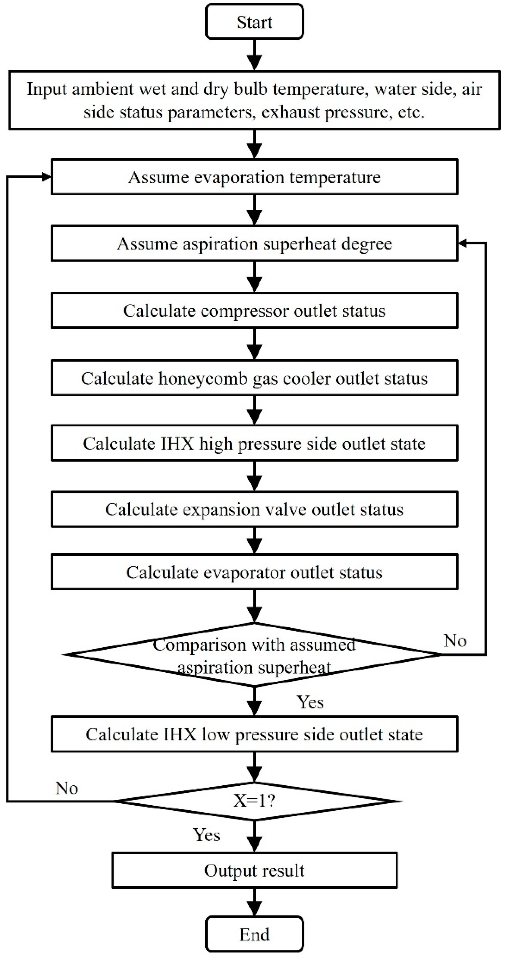
  • The inlet flow rate of each component should be equal to the outlet flow rate of the previous component. The calculation flow of this procedure is shown in Figure 4.

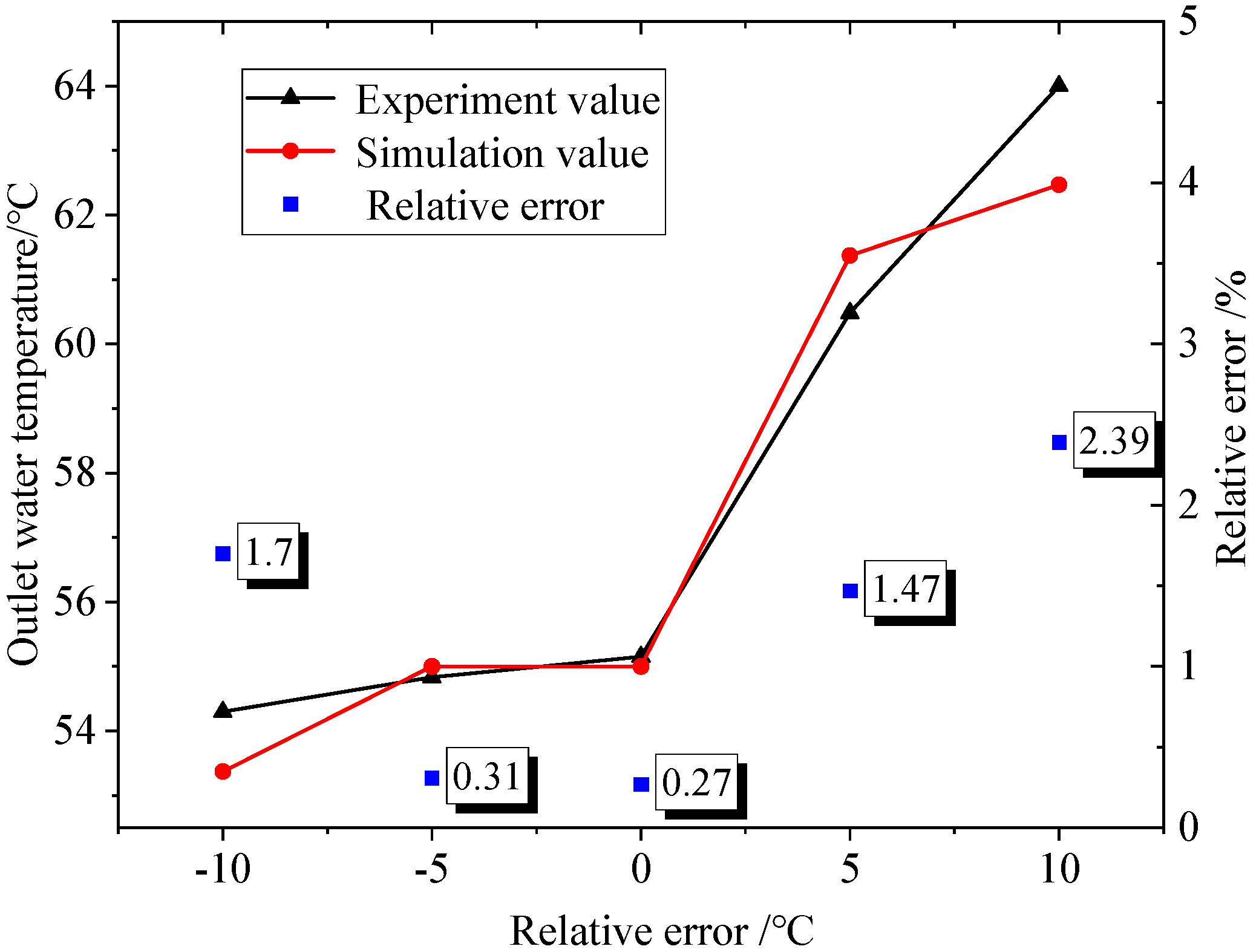
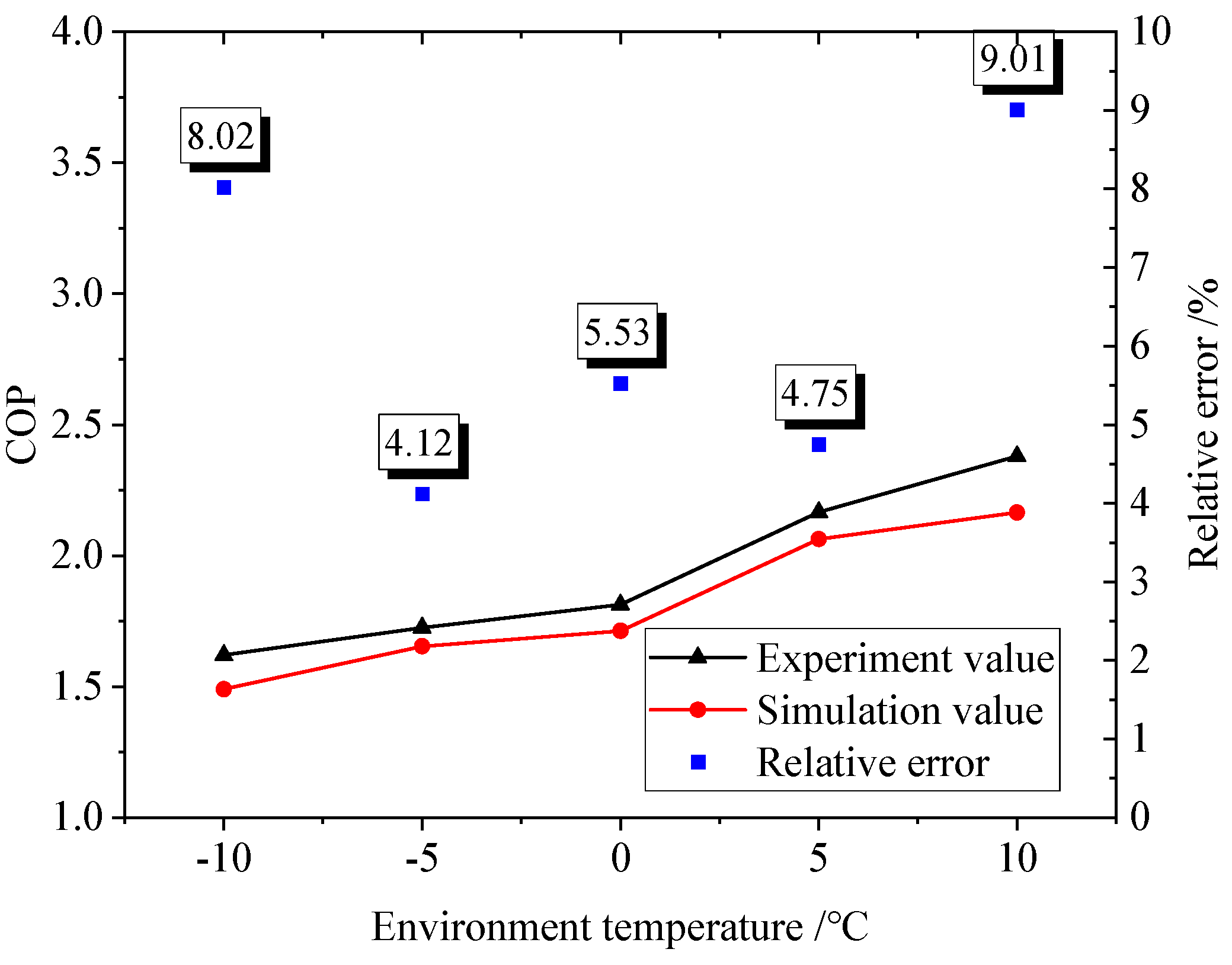
2.3. Model Validation

Because the structure and heat transfer characteristics of the tube-in-tube gas cooler were similar to those of the 1st-layer honeycomb gas cooler, in order to reduce the occurrence of unsafe accidents and waste of resources, the reliability of the simulation model was initially verified in the research stage of this paper by using a CO2 air-source heat pump test bench with a tube-in-tube gas cooler.
The schematic diagram of the test bench and the testing procedure are detailed in the literature [28]. Photographs of the test bench are shown in Figure 5, and detailed parameters of the system components are shown in Table 1. The specific experimental conditions are shown in Table 2.
As shown in Figure 6 and Figure 7, the simulation results of heat pump water supply temperature and system performance COP compared with experimental values verified the correctness and reliability of the model, whose maximum errors were less than 3% and 10%, respectively.

3. Exergy Analysis Model

3.1. Theoretical Basis

When a system changes reversibly from an arbitrary state to a state in equilibrium with a given environment, a portion of the energy can theoretically be converted indefinitely to any other form, called exergy and also called effective energy. The other part of the energy that cannot be used or lost is called anergy. During the thermal process, the sum of both remains constant. Energy can only be converted from the high quality of exergy to the low quality of anergy. The exergy efficiency of a system gives an indication of the extent to which the system utilizes energy and reflects the rationality of the system structure and efficiency.
The exergy analysis method is based on the second law of thermodynamics, and it can be used to determine the location and magnitude of the irreversible losses in a system and can be used as a basis for making recommendations for system improvements. In heat pump systems, the temperature difference between the hot and cold fluids in the heat exchanger and the irreversibility of the compression and throttling processes can cause the system to suffer from exergy destruction. In this paper, based on the established simulation model of the CO2 heat pump, the parameters of various state points of each component in a stable operation are calculated. It also calculates the system and components’ exergy efficiency and exergy destruction according to the methodology of the exergy analysis, thus pointing out the potential for the improvement of the system and the priority of the improved components. This work is beneficial for improving the system performance and expanding the application fields.

3.2. Exergy Modeling

Exergy can be divided into chemical exergy, kinetic exergy, latent exergy, and physical exergy. In the CO2 heat pump system described in this paper, no chemical reaction occurs, and the system is a one-dimensional stable system; therefore the chemical exergy, kinetic exergy, and latent exergy can be neglected, and only the physical exergy should be considered in the exergy analysis of the system.
The specific physical exergy ePH is the physical exergy per unit mass, and it contains the thermal exergy eT and mechanical exergy eM; the former is related to temperature, and the latter is caused by pressure as shown in Equation (13).
e j = e j P H = e j T + e j M = [ ( h j h j , x ) T 0 ( s j s j , x ) ] P = const + [ ( h j , x h j , 0 ) T 0 ( s j , x s j , 0 ) ] T = const
where the subscript j indicates the state point, the subscript 0 indicates the selected reference ambient state, and the subscript x refers to the condition at the reference ambient temperature T0 and the pressure Pj at the state point j.
The evaluation indexes of the system exergy analysis mainly include the exergy destruction ED, exergy efficiency ε, exergy destruction percentage y, and exergy destruction coefficient Ω.
In the thermodynamic process, the fuel exergy EF is the input energy of a component, and the product exergy EP refers to the part of the input energy that is utilized to produce the due thermodynamic effect. The difference between the two is the exergy destruction as shown in Equation (14). For a transcritical CO2 heat pump, the fuel exergy of the system is the energy consumed by the compressor, i.e., the compressor power consumption, as in Equation (15). The product exergy of the system is the product energy of the gas cooler as in Equation (16), and the system exergy destruction is the sum of the exergy destruction of all the components as in Equation (17). Since all the thermodynamic processes in nature are irreversible and necessarily involve energy loss and dissipation, the exergy destruction is constantly greater than zero.
E D = E F E P
E F , sys = E F , comp = W t
E P , s y s = E P , g c
E D , s y s = E D , k
The exergy efficiency ε is the ratio of the components’ product exergy to their fuel exergy, which can indicate the extent of the components’ utilization of the input energy and can provide guidance for targeted component optimization and modification. The exergy efficiency can be calculated by Equation (18).
ε k = E P , k E F , k
The exergy destruction percentage y is the proportion of the exergy destruction of a component to the total exergy destruction of the system, and the sum of the exergy destruction percentages of all the components is one. This parameter can clarify the contribution of the exergy destruction of each component in the system to the total exergy destruction of the system and can provide a basis for the optimization order of each component. The exergy destruction percentage can be calculated by Equation (19):
y k = E D , k E D , s y s
The exergy destruction coefficient Ω is the ratio of the exergy destruction of a component to the total fuel exergy of the system, which reveals the degree of impact of the exergy destruction of each component in the system. The exergy destruction coefficient is defined as shown in Equation (20):
Ω k = E D , k E F , s y s
Based on the above theoretical basis for exergy modeling, Table 3 collates the equations for the fuel exergy, product exergy, and exergy destruction of each component in the CO2 heat pump and of the system.

4. Results and Discussion

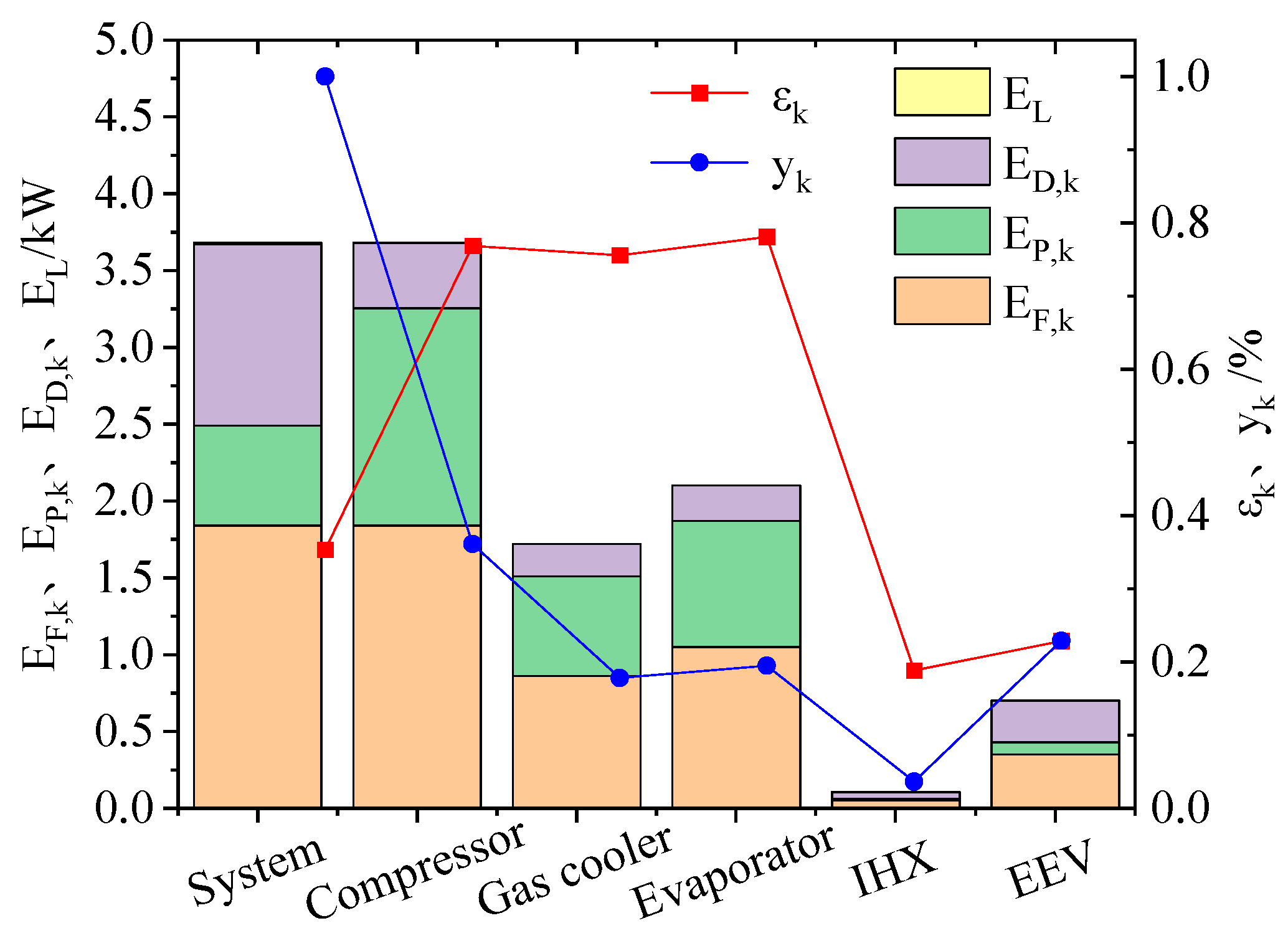
4.1. Exergy Destruction and Exergy Efficiency of the System and Each Component

In this section, the exergy destruction and exergy efficiency are calculated for each component and the whole system based on Equations (13)–(20) under nominal operating conditions; i.e., the inlet and outlet water temperatures are 17 ± 1.0 °C and 65 ± 2.0 °C, and the air dry- and wet-bulb temperatures are 16 ± 1.0 °C and 12 ± 1.0 °C, respectively. The exergy analysis results are presented in Table 4, which shows the distribution and magnitude of the irreversible losses in each component of the system.
From Figure 8, it can be seen that the exergy efficiency of the system is 35.33% under nominal working conditions, which means that the heat pump system still has a large potential for optimization in terms of energy utilization. The three components with the largest exergy destruction percentage are the compressor, throttle valve, and evaporator, whose exergy destruction percentages are 36.13%, 22.90%, and 19.51%, respectively. These high-exergy-destruction-percentage components are the main reason for the large irreversible losses of the system, so optimizing and improving their performance is the key direction for the optimization and upgrading of the system. The throttle valve shows a low exergy efficiency, which is only 22.86%. The reason for this phenomenon is to throttle the CO2 gas at the outlet of the gas cooler to a two-phase state with equal enthalpy, and in this process, it generates the conversion of multiple states of the refrigerant, which makes the availability of energy decrease. Therefore, to improve the system performance and energy efficiency, the throttle valve must be optimized. Common measures include structural optimization or replacing the throttle valve with an expander, injector, etc. The exergy efficiency of the honeycomb gas cooler is 75.58%, which is relatively high, meaning that the honeycomb gas cooler is able to meet the demand for hot water preparation for design conditions with a high energy efficiency. The exergy destruction of the honeycomb gas cooler is relatively small, which is 17.81%. The exergy efficiency of the IHX is extremely low at 18.87%, but at the same time, the exergy destruction of the IHX is the smallest among the system components, accounting for only 3.65%.

4.2. Effect of Different Forms of Gas Coolers on Exergy Destruction and Exergy Efficiency of Each Component

In order to clarify the difference in energy utilization between the honeycomb type of gas cooler and the tube-in-tube type of gas cooler, the thermogravimetric ratio of the two forms of gas coolers is kept consistent in this section. A comparative analysis is conducted under four typical operating conditions throughout the year (Table 5) [29], and the results are shown in Figure 9. It can be seen that the COP of the heat pump with the honeycomb gas cooler is significantly higher than that of the heat pump with the tube-in-tube gas cooler under the same conditions. The difference in the COP is even greater in summer conditions, and the COP of the heat pump with the honeycomb gas cooler is about twice as high as that of the tube-in-tube type. As the typical operating conditions change from summer to a low temperature, the exergy efficiency of the gas cooler increases; this is because the inlet water temperature is lower under low-temperature operating conditions, the heat transfer temperature difference is smaller, and the exergy destruction is lower. The system exergy efficiency decreases because the ambient temperature decreases and because the compressor power consumption increases; i.e., the denominator of the system exergy efficiency increases. Its growth rate is greater than the growth rate of the numerator (the gas cooler product exergy), so the system exergy efficiency is decreasing. In addition, the exergy efficiency of the honeycomb gas cooler is 20.51%, 14.34%, 9.76%, and 7.20% higher under the four operating conditions, and the system exergy efficiency is 52.78%, 55.19%, 53.68%, and 43.89% higher, respectively, than that of the basic cycle. This means that the honeycomb gas cooler has a higher energy efficiency.

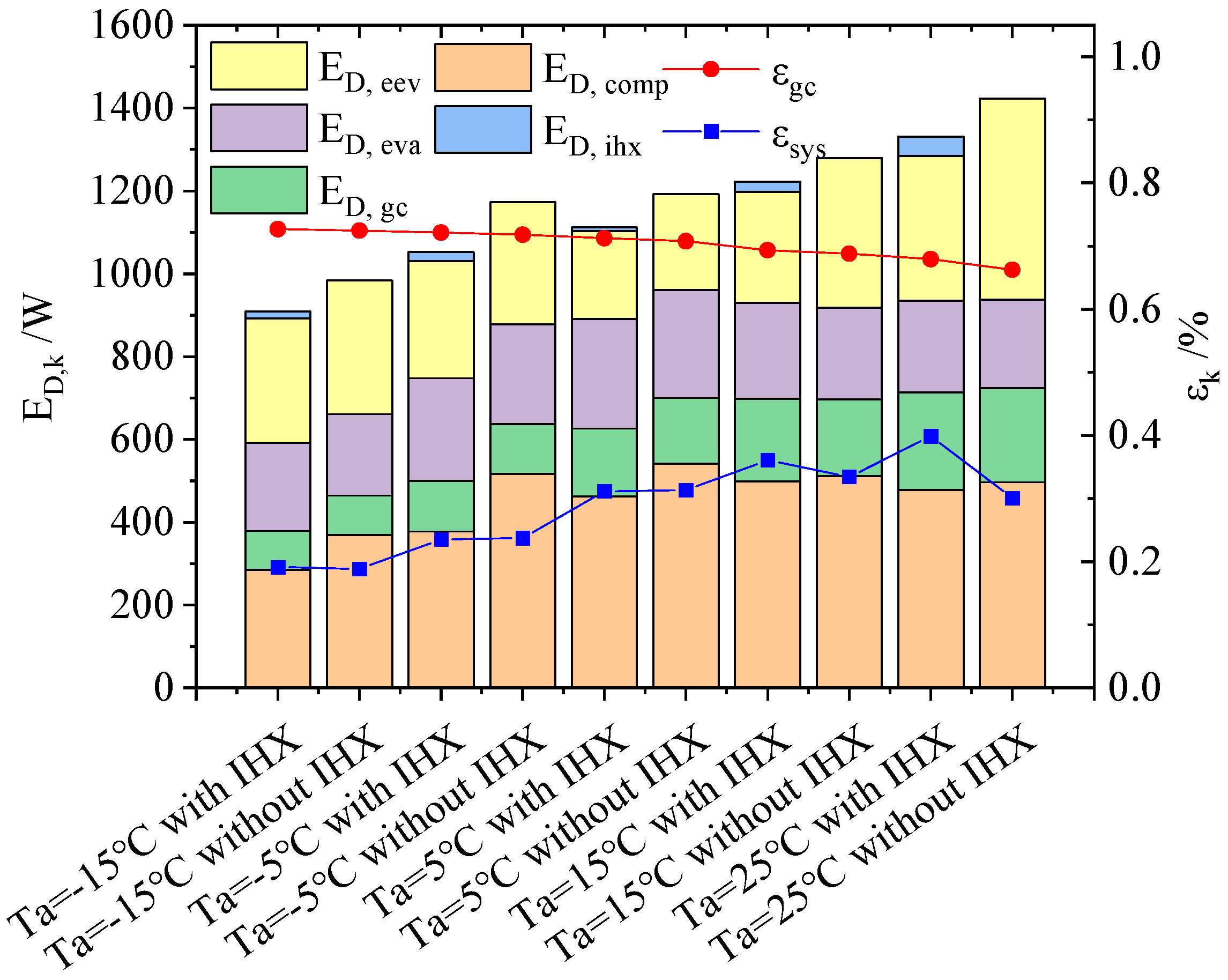
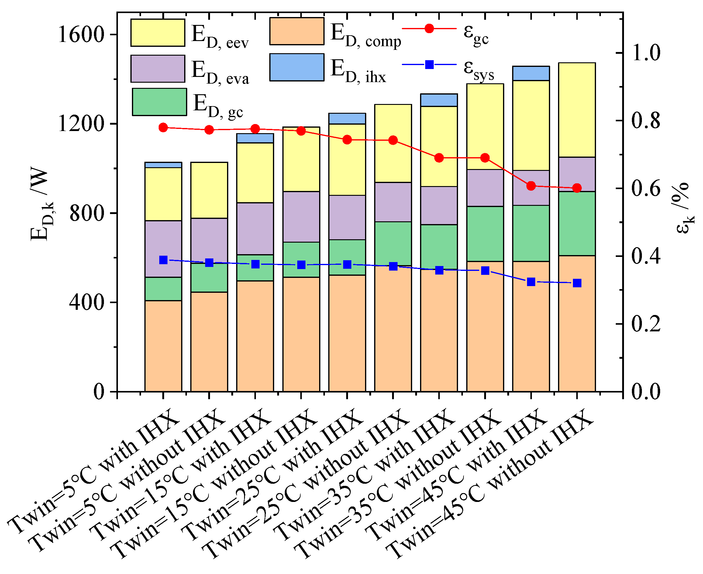
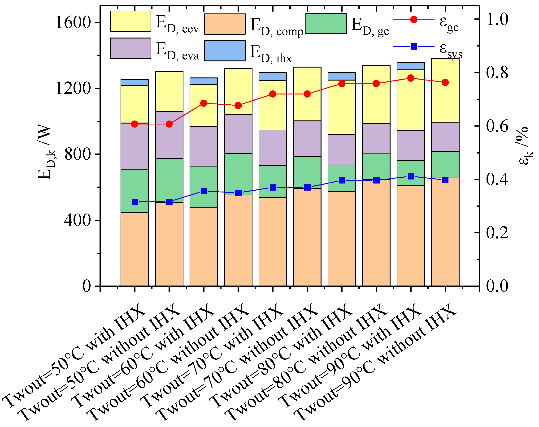
4.3. Effect of Different Working Conditions on Exergy Destruction and Exergy Efficiency of Each Component

In this section, the exergy efficiency and exergy destruction of the CO2 heat pump system with or without the IHX are investigated under the different ambient temperature conditions. Namely, the inlet and outlet water temperatures are 17/65 °C, respectively. As shown in Figure 10, the exergy efficiency of the system increases as the ambient temperature increases, and the exergy efficiency of the system with the IHX is higher than that without the IHX under each operating condition. When the ambient temperature rises from −15 °C to 25 °C, the exergy efficiency of the system with the IHX increases from 19.16% to 39.88%, increasing by 108.09%; the exergy efficiency of the system without the IHX increases from 18.87% to 30.06%, increasing by 59.29%. The exergy efficiency of the honeycomb gas cooler decreases with an increasing ambient temperature; however, the rate of the decrease is small, and the exergy efficiency of the gas cooler with the IHX is higher than that without the IHX under each operating condition. When the ambient temperature increases from −15 °C to 25 °C, the exergy efficiency of the gas cooler with the IHX decreases from 72.7% to 67.95%, decreasing by 6.53%, while the exergy efficiency of the gas cooler without it decreases from 72.47% to 66.26%, decreasing by 8.58%.
In terms of energy loss, with an increase in the ambient temperature, the system exergy destruction gradually increases, and the heat pump system exergy destruction with the IHX is smaller than the system exergy destruction without the IHX. When the ambient temperature rises from −15 °C to 25 °C, the system exergy destruction with the IHX increases from 909 W to 1331 W, increasing by 46.49%; the exergy destruction of the system without the IHX increases from 983 W to 1473 W, increasing by 49.74%. Meanwhile, the exergy destruction of the honeycomb gas cooler gradually increases with a rising ambient temperature, so the transcritical CO2 heat pump is superior in a low-temperature environment.
As shown in Figure 11, the exergy efficiency and exergy destruction of the CO2 heat pump system with or without the IHX at different inlet water temperatures are analyzed. The outlet water temperature is 65 °C, and the ambient temperature is 16 °C. The exergy efficiency of the system decreases as the inlet temperature increases; the exergy efficiency of the system with the IHX is higher than the exergy efficiency of the system without the IHX under each operating condition, but the difference is small. When the inlet water temperature increases from 5 °C to 45 °C, the exergy efficiency of the system with the IHX decreases from 38.95% to 32.45%, decreasing by 16.69%; the exergy efficiency of the system without the IHX decreases from 38.17% to 32.11%, decreasing by 15.88%. The exergy efficiency of the honeycomb gas cooler decreases as the inlet water temperature increases, and the exergy efficiency of the gas cooler with the IHX is higher than the exergy efficiency of the gas cooler without the IHX under each operating condition. When the inlet water temperature increases from 5 °C to 45 °C, the exergy efficiency of the gas cooler with the IHX decreases from 77.98% to 60.75%, decreasing by 22.10%; the exergy efficiency of the gas cooler without the IHX decreases from 77.28% to 60.13%, decreasing by 22.18%.
In terms of energy loss, with an increase in the inlet water temperature, the system exergy destruction gradually increases, and when the inlet water temperature increases from 5 °C to 45 °C, the system exergy destruction with the IHX increases from 1028 W to 1458 W, increasing by 41.85%; the system exergy destruction without the IHX increases from 1027 W to 1474 W, increasing by 43.50%. Under the same inlet water temperature, the exergy destruction of the heat pump system with the IHX is smaller than that without the IHX. Taking the inlet water temperature of 5 °C as an example, the exergy destruction of the system with the IHX is about 0.07% lower than that of the system without the IHX. Taking the inlet water temperature of 45 °C as an example, the exergy destruction of the system with the IHX is about 1.08% lower than that of the system without the IHX. Meanwhile, the exergy destruction of the compressor increases gradually with an increase in the inlet water temperature, the exergy destruction of the honeycomb gas cooler increases gradually with an increase in the inlet water temperature, and the exergy destruction of the throttle valve increases gradually with an increase in the inlet water temperature.
As shown in Figure 12, the exergy efficiency and exergy destruction of the CO2 heat pump system with or without the IHX at different outlet water temperatures are analyzed. The inlet water temperature is 9 °C, and the ambient temperature is 16 °C. The exergy efficiency of the system increases with an increase in the outlet water temperature, and the exergy efficiency of the system with the IHX is equal to or slightly higher than the exergy efficiency of the heat pump system without the IHX under each operating condition. When the outlet water temperature increases from 50 °C to 90 °C, the exergy efficiency of the system with the IHX increases from 31.65% to 41.18%, increasing by 30.12%; the exergy efficiency of the system without the IHX increases from 31.65% to 39.80%, increasing by 25.77%. The exergy efficiency of the honeycomb gas cooler increases with an increase in the outlet water temperature, and when the outlet water temperature increases from 50 °C to 90 °C, the exergy efficiency of the gas cooler with the IHX increases from 60.73% to 77.93%, increasing by 28.32%; the exergy efficiency of the gas cooler without the IHX increases from 60.73% to 76.33%, increasing by 25.68%.
In terms of energy loss, with an increase in the outlet water temperature, the system exergy destruction gradually increases, and when the outlet water temperature rises from 50 °C to 90 °C, the system exergy destruction with the IHX increases from 1254 W to 1355 W, increasing by 8.05%; the system exergy destruction without the IHX increases from 1300 W to 1381 W, increasing by 6.19%. Under the same outlet water temperature conditions, the exergy destruction of the heat pump system with the IHX is less than the exergy destruction of the system without the IHX, and taking the outlet water temperature of 50 °C as an example, the exergy destruction of the system with the IHX is about 3.58% lower than the exergy destruction of the system without the IHX. Taking the outlet water temperature of 90 °C as an example, the exergy destruction of the system with the IHX is about 1.90% lower than the exergy destruction of the system without the IHX. Meanwhile, the exergy destruction of the compressor gradually increases with an increase in the outlet water temperature, the exergy destruction of the honeycomb gas cooler gradually decreases with an increase in the outlet water temperature, and the exergy destruction of the throttle valve gradually increases with an increase in the inlet water temperature.

4.4. System Improvement and Optimization Suggestions

In summary, the exergy destruction and exergy destruction percentage of the compressor are the largest among the system components, which is mainly due to the nonisentropic compression caused by the friction and other factors in the compressor. In order to reduce the exergy destruction of the compressor, consideration can be given to improving the structural design, selecting higher-quality lubricating oil to reduce friction, reducing the heat dissipation loss, and improving the isentropic compression efficiency of the compressor.
Secondly, the next largest component is the exergy destruction of the throttle valve, whose main function is to throttle the CO2 gas at the outlet of the gas cooler to a two-phase state with equal enthalpy, and in this process, it produces the conversion of multiple states of the refrigerant, which makes the availability of energy decrease. Therefore, the throttle valve must be optimized to improve the system performance and energy efficiency. Common measures include structural optimization or replacing the throttle valve with an expander, injector, etc.
The exergy destruction ranking of each component under different working conditions is either third or fourth for the evaporator and the honeycomb gas cooler. For the evaporator, this part of exergy destruction is caused by the temperature difference between the hot and cold fluid inside the heat exchanger. The larger the temperature difference is, the larger the irreversible loss and the lower the exergy efficiency of the heat exchanger. The exergy efficiency can be improved by increasing the heat transfer area and reducing the temperature difference. However, a larger heat transfer area makes the heat exchanger cost more expensive, so thermodynamic knowledge should be considered to estimate its cost. For the honeycomb gas cooler, it is known from the literature [24] that its heat transfer area is large and that the heat transfer performance is good, and the difference between the CO2 outlet temperature of the gas cooler and the inlet water temperature can reach within 5 °C. It is suggested that the exergy efficiency can be further improved by reducing the inlet water temperature or increasing the outlet water temperature.
The exergy efficiency of the IHX is low; however, the percentage of exergy destruction is small, and the improved gain is not very large. The application of the IHX under different operating conditions reduces the exergy destruction and increases the exergy efficiency of the CO2 heat pump system, so the application of the IHX has positive significance for the energy utilization of the CO2 heat pump system.

5. Conclusions

In this work, an exergy analysis is performed for a CO2 system operation integrated with a honeycomb gas cooler and is compared with a heat pump system with a tube-in-tube gas cooler. Also, the optimization potential of the system is pointed out. The main conclusions are as follows:
  • The system exergy efficiency is 35.33% under nominal operating conditions, which has a large potential for improvement in energy utilization. The three components with the largest exergy destruction percentage are the compressor, throttle valve, and evaporator in the order of 36.13%, 22.90%, and 19.51%, respectively.
  • Under the same conditions, the COP of the heat pump with the honeycomb gas cooler is significantly higher than that of the heat pump with the tube-in-tube gas cooler. The exergy efficiency of the honeycomb gas cooler is 20.51%, 14.34%, 9.76%, and 7.20% higher than that of the gas cooler type under the four typical operating conditions. The system exergy efficiencies are 52.78%, 55.19%, 53.68%, and 43.89% higher, respectively. This implies that the honeycomb gas cooler has higher energy utilization.
  • Suggestions for the improvement and optimization of the key components are made: The compressor is the key object of system improvement, and the exergy destruction of the compressor can be reduced by improving the structural design, using higher-quality lubricating oil, etc. Next is the throttle valve; common measures include structural optimization or using an expander or injector instead. The exergy destruction of the evaporator is mainly caused by the heat exchange temperature difference in the heat exchanger; the exergy efficiency can be improved by increasing the heat exchange area and reducing the heat exchange temperature difference.

Author Contributions

Conceptualization, Z.W. and F.W.; methodology, Z.W. and P.Z.; software, Y.Z.; validation, Y.Z.; formal analysis, X.J. and P.Z.; investigation, Y.Z.; resources, Y.Z.; data curation, Y.Z.; writing—original draft preparation, Y.Z.; writing—review and editing, Z.M.; visualization, Z.W.; supervision, Z.W. and F.W.; project administration, C.H.; funding acquisition, F.W. All authors have read and agreed to the published version of the manuscript.

Funding

This research was funded by the National Natural Science Foundation of China (No. 52076158 and 52004207), the Xi’an Municipal Science and Technology Foundation (No. 21XJZZ0038), the Natural Science Basic Research Plan in the Shaanxi Province of China (No. 2023-JC-YB-456), and the Research and Development Program of the Shaanxi Province (No. 2023-YBGY-283).

Data Availability Statement

Not applicable.

Conflicts of Interest

The authors declare no conflict of interest.

Nomenclature

AHeat exchange area, m2
cpSpecific heat capacity, J/kg·K
EDExergy destruction, kW
EFFuel exergy, kW
EPProduct exergy, kW
PPressure of CO2, MPa
QHeat transfer capacity, kW
VGas delivery volume of the compressor, m3/r
WCompressor power consumption, kW
hEnthalpy, kJ/ kg
mMass flow rate, kg/s
nNumber of layers in the honeycomb CO2 gas cooler
tTemperature of fluid, °C
yExergy destruction percentage, %
ΩExergy destruction coefficient, %
αHeat transfer coefficient, W/(m2·K)
δWall thickness, m
εExergy efficiency, %
ηEfficiency, %
λThermal conductivity, W/(m·K)
ρFluid density, kg/m3

Abbreviations

EEVElectronic expansion valve
IHXInternal heat exchanger

Subscript

aAir
comCompressor
eevElectronic expansion valve
evaEvaporator
gcGas cooler
ihxInternal heat exchanger
kComponent
fFluid
inInlet
isIsentropic
jMicroelement
outOutlet
rRefrigerant
sysSystem
wWater
wallTube wall

References

  1. Liu, S.C.; Zheng, L.; Dai, B.M.; Zhong, Z.; Li, H.; Song, M.; Sun, Z. Energetic, economic and environmental analysis of air source transcritical CO2 heat pump system for residential heating in China. Appl. Therm. Eng. 2019, 148, 1425–1439. [Google Scholar] [CrossRef]
  2. Zhang, Y.X.; Wang, S.N.; Shao, W.; Hao, J. Feasible distributed energy supply options for household energy use in China from a carbon neutral perspective. Int. J. Environ. Res. Public Health 2021, 18, 12992. [Google Scholar] [CrossRef]
  3. Barta, R.B.; Groll, E.A.; Ziviani, D. Review of stationary and transport CO2 refrigeration and air conditioning technologies. Appl. Therm. Eng. 2021, 185, 116422. [Google Scholar] [CrossRef]
  4. Nawaz, K.; Shen, B.; Elatar, A.; Baxter, V.; Abdelaziz, O. Performance optimization of CO2 heat pump water heater. Int. J. Refrig. 2018, 85, 213–228. [Google Scholar] [CrossRef]
  5. Wang, J.; Belusko, M.; Semsarilar, H.; Evans, M.; Liu, M.; Bruno, F. An optimisation study on a real-world transcritical CO2 heat pump system with a flash gas bypass. Energy Convers. Manag. 2022, 251, 114995. [Google Scholar] [CrossRef]
  6. Cao, F.; Ye, Z.L.; Wang, Y.K. Experimental investigation on the influence of internal heat exchanger in a transcritical CO2 heat pump water heater. Appl. Therm. Eng. 2020, 168, 114855. [Google Scholar] [CrossRef]
  7. Wang, J.; Belusko, M.; Evans, M.; Liu, M.; Zhao, C.; Bruno, F. A comprehensive review and analysis on CO2 heat pump water heaters. Energy Convers. Manag. X 2022, 15, 100277. [Google Scholar] [CrossRef]
  8. Cui, C.; Zong, S.; Song, Y.L.; Yin, X.; Cao, F. Experimental investigation of the extreme seeking control on a transcritical CO2 heat pump water heater. Int. J. Refrig. 2022, 133, 111–122. [Google Scholar] [CrossRef]
  9. Wang, Y.K.; Ye, Z.L.; Song, Y.L.; Yin, X.; Cao, F. Energy, exergy, economic and environmental analysis of refrigerant charge in air source transcritical carbon dioxide heat pump water heater. Energy Convers. Manag. 2020, 223, 113209. [Google Scholar] [CrossRef]
  10. Wang, Z.H.; Li, G.C.; Wang, F.H. Performance analysis and operation optimization of air-to-water CO2 heat pump with phase change thermal storage. Energy Build. 2020, 209, 109738. [Google Scholar] [CrossRef]
  11. Dai, B.; Liu, C.; Liu, S.; Wang, D.; Wang, Q.; Zou, T.; Zhou, X. Life cycle techno-enviro-economic assessment of dual-temperature evaporation transcritical CO2 high-temperature heat pump systems for industrial waste heat recovery. Appl. Therm. Eng. 2023, 219, 119570. [Google Scholar] [CrossRef]
  12. Illán-Gómez, F.; Sena-Cuevas, V.F.; García-Cascales, J.R.; Velasco, F.J. Analysis of the optimal gas cooler pressure of a CO2 heat pump with gas bypass for hot water generation. Appl. Therm. Eng. 2021, 182, 116110. [Google Scholar] [CrossRef]
  13. Peng, X.; Wang, D.B.; Wang, G.H.; Yang, Y.; Xiang, S. Numerical investigation on the heating performance of a transcritical CO2 vapor-injection heat pump system. Appl. Therm. Eng. 2020, 166, 114656. [Google Scholar] [CrossRef]
  14. Wu, Z.X.; Zhang, Y.F.; Sheng, Y. Energy, exergy, economic(3E) analysis and multi-objective optimization of a novel dual functional integration system. Energy Convers. Manag. 2019, 199, 111962. [Google Scholar] [CrossRef]
  15. Sun, Z.L.; Wang, Q.F.; Xie, Z.Y.; Liu, S.; Su, D.; Cui, Q. Energy and exergy analysis of low GWP refrigerants in cascade refrigeration system. Energy 2019, 170, 1170–1180. [Google Scholar] [CrossRef]
  16. Patil, O.S.; Shet, S.A.; Jadhao, M.; Agrawal, N. Energetic and exergetic studies of modified CO2 transcritical refrigeration cycles. Int. J. Low Carbon Technol. 2021, 16, 171–180. [Google Scholar] [CrossRef]
  17. Wu, J.X.; Sun, S.J.; Song, Q.L.; Sun, D.; Wang, D.; Li, J. Energy, exergy, exergoeconomic and environmental (4E) analysis of cascade heat pump, recuperative heat pump and carbon dioxide heat pump with different temperature lifts. Renew. Energy 2023, 207, 407–421. [Google Scholar] [CrossRef]
  18. Li, Y.M.; Wang, C.C. Investigation of the performance of a transcritical CO2 heat pump system subject to heated water conditions: Perspective from the second law. Appl. Therm. Eng. 2021, 193, 116999. [Google Scholar] [CrossRef]
  19. Liu, R.J.; Gao, F.L.; Liang, K.F.; Wang, L.; Wang, M.; Mi, G.; Li, Y. Thermodynamic Evaluation of Transcritical CO2 Heat Pump Considering Temperature Matching under the Constraint of Heat Transfer Pinch Point. J. Therm. Sci. 2021, 30, 869–879. [Google Scholar] [CrossRef]
  20. Maddah, S.; Safaei, M.R. Determination of the optimal discharge pressure of the transcritical CO2 heat pump cycles for heating and cooling performances based on new correlation. J. Therm. Anal. Calorim. Int. Forum Therm. Stud. 2021, 145, 1537–1546. [Google Scholar] [CrossRef]
  21. Wang, Y.K.; Ye, Z.L.; Yin, X.; Song, Y.; Cao, F. Energy, exergy and exergoeconomic evaluation of the air source transcritical CO2 heat pump with internal heat exchanger for space heating. Int. J. Refrig. 2021, 130, 14–26. [Google Scholar] [CrossRef]
  22. Ghazizade-Ahsaee, H.; Ameri, M. Effects of using expander and internal heat exchanger on carbon dioxide direct-expansion geothermal heat pump. Appl. Therm. Eng. 2018, 136, 389–407. [Google Scholar] [CrossRef]
  23. Wang, Y.; He, Y.; Song, Y.; Yin, X.; Cao, F.; Wang, X. Energy and exergy analysis of the air source transcritical CO2 heat pump water heater using CO2-based mixture as working fluid. Energies 2021, 14, 4470. [Google Scholar] [CrossRef]
  24. Zhang, Y.X.; Wei, X.L.; Qin, X. Experimental study on energy, exergy, and exergoeconomic analyses of a novel compression/ejector transcritical CO2 heat pump system with dual heat sources. Energy Convers. Manag. 2022, 271, 116343. [Google Scholar] [CrossRef]
  25. Wang, Z.H.; Li, G.C.; Zhang, Y.J.; Wang, F.; Jiang, X.; Ma, Z. Flow and heat transfer investigation of supercritical carbon dioxide in a novel biomimetic honeycomb fractal gas cooler of transcritical CO2 heat pumps. Therm. Sci. Eng. Prog. 2023, 37, 101533. [Google Scholar] [CrossRef]
  26. Li, G.C.; Wang, Z.H.; Wang, F.H.; Zhang, Y. Numerical investigation on the performance characteristics of a novel biomimetic honeycomb fractal gas cooler of transcritical CO2 heat pump. J. Build. Eng. 2022, 59, 105091. [Google Scholar] [CrossRef]
  27. Zhang, Y.J.; Wang, Z.H.; Jiang, X.; Xu, K.; Ma, Z.; Dou, W. Heat transfer and performance enhancement investigation of biomimetic honeycomb gas coolers in transcritical CO2 heat pumps. Appl. Therm. Eng. 2023, 230, 120645. [Google Scholar] [CrossRef]
  28. Wang, Z.H.; Wang, F.H.; Li, G.C.; Song, M.; Ma, Z.; Ren, H.; Li, K. Experimental investigation on thermal characteristics of transcritical CO2 heat pump unit combined with thermal energy storage for residential heating. Appl. Therm. Eng. 2020, 165, 114505. [Google Scholar] [CrossRef]
  29. Ma, Y.T.; Wang, P.; Zhang, Q.C.; Li, M.X.; Cai, S.Q. Development status of CO2 heat pump water heaters. Refrig. Air Cond. 2018, 18, 67–71. (In Chinese) [Google Scholar]
Figure 1. The cross-sectional schematic of the honeycomb gas cooler’s different honeycomb layers [27].
Buildings 13 02147 g001
Figure 2. Physical model structure of the 3-layers honeycomb gas cooler: (a) external view, (b) perspective view, and (c) cutaway view [27].
Buildings 13 02147 g002
Figure 3. Transcritical CO2 heat pump cycle with IHX.
Buildings 13 02147 g003
Figure 4. CO2 heat pump cycle calculation flow chart.
Buildings 13 02147 g004
Figure 5. Photo of the experimental prototype [28].
Buildings 13 02147 g005
Figure 6. CO2 heat pump water supply temperature comparison.
Buildings 13 02147 g006
Figure 7. CO2 heat pump COP comparison.
Buildings 13 02147 g007
Figure 8. Exergy analysis results of systems and components under nominal operating conditions.
Buildings 13 02147 g008
Figure 9. Exergy comparison results of honeycomb gas cooler and tube-in-tube gas cooler under typical operating conditions.
Buildings 13 02147 g009
Figure 10. Exergy analysis results of each component at different ambient temperatures.
Buildings 13 02147 g010
Figure 11. Exergy analysis results of each component at different inlet water temperatures.
Buildings 13 02147 g011
Figure 12. Exergy analysis results of each component at different outlet water temperatures.
Buildings 13 02147 g012
Table 1. Table of structural parameters of each component of the experimental prototype.
ComponentsTypeStructural Parameters
CompressorRotor compressorMotor frequency: 50 Hz
Power: 2.19 kW
Theoretical volume: 1.44 m3/h
Gas coolerCoaxial tube-in-tube type of heat exchangerInner tube: 22.2 mm diameter, 1.2 mm wall thickness, made of stainless steel
Inner tube: 19 mm diameter, 0.9 mm wall thickness, made of copper
Length of heat exchange section: 18.57 m
EvaporatorFinned-tube heat exchangerTube diameter: 7.94 mm
Tube wall thickness: 0.7 mm
Tube material: copper
Fin thickness: 0.11 mm
Fin material: aluminum sleeve
Fin spacing: 2.0 mm
Number of tubes in a single row: 30
Number and length of loops: 5/14.4 m
IHXCoaxial casing type of heat exchangerOuter tube: 22 mm diameter, made of copper
Inner tube: tube diameter of 12.7 mm, material is copper
Length of heat exchange section: 1.2 m
Expansion valveCO2 heat pump cross-critical cycle special electronic expansion valveValve orifice diameter: Ø 1.4 mm
Maximum pressure limit: 14 MPa
Table 2. Table of working condition parameters.
Working ConditionCase 1Case 2Case 3Case 4Case 5
Ambient temperature/°C−10−50510
Water flow/m3·h−10.2
Inlet water temperature/°C35
Table 3. Calculation formula of the fuel exergy, product exergy, and exergy destruction of each component in the CO2 heat pump system and of the system.
ComponentFuel ExergyProduct ExergyExergy Destruction
Compressor E ˙ F , c o m p = W c o m p E P , c o m p = m 1 ( e 2 e 1 ) E D , c o m p = E F , c o m p E P , c o m p
Gas cooler E F , gc = m 2 ( e 2 e 3 ) E P , gc = m 5 ( e 6 e 5 ) E D , gc = E F , gc E P , gc
Evaporator E F , eva = m 4 ( e 4 e 1 ) E P , e v a = m 7 ( e 8 e 7 ) E D , e v a = E F , e v a E P , e v a
IHX E F , ihx = m 3 ( e 3 e 3 ) E P , ihx = m 1 ( e 1 e 1 ) E D , ihx = E F , ihx E P , ihx
EEV E F , eev = m 3 ( e 3 M e 4 M + e 3 T ) E P , e e v = m 3 e 4 T E D , e e v = E F , e e v E P , e e v
System E F , s y s = E F , c o m p E P , s y s = E P , g c E D , s y s = E D
Table 4. Exergy analysis results of CO2 heat pump system under nominal working conditions.
Component E ˙ F , k /kW E ˙ P , k /kW E ˙ D , k /kW E ˙ L /kW ε k /% Ω k /% y k
Compressor1.8401.4140.426-76.8523.1536.13
Gas cooler0.8600.6500.210-75.5811.4117.81
Evaporator1.0500.8200.230-78.1012.5019.51
IHX0.0530.0100.043-18.872.343.65
EEV0.3500.0800.270-22.8614.6722.90
System1.8400.6501.1790.01135.3364.08100.00
Table 5. Four typical operating conditions throughout the year.
ConditionWater Inlet Temperature/°CWater Outlet Temperature/°CAir Dry-Bulb Temperature/°CAir Wet-Bulb Temperature/°C
Summer24 ± 1.065 ± 225 ± 1.021 ± 1.0
Nominal17 ± 1.065 ± 216 ± 1.012 ± 1.0
Winter9 ± 1.065 ± 27 ± 1.06 ± 1.0
Low temperature5 ± 1.065 ± 2−12 ± 1.0−14 ± 1.0
Disclaimer/Publisher’s Note: The statements, opinions and data contained in all publications are solely those of the individual author(s) and contributor(s) and not of MDPI and/or the editor(s). MDPI and/or the editor(s) disclaim responsibility for any injury to people or property resulting from any ideas, methods, instructions or products referred to in the content.

