Article

Practical Investigation on the Strengthening of the Built-Up Steel Main Girder of a Metro Station with Carbon-Fiber-Reinforced Polymer on the Inside Part of the Tensioned Flange

by
Mohamed A. M. A. Mahmoud
1,*,
Phan Viet Nhut
1,2 and
Yukihiro Matsumoto
1
1
Department of Architecture and Civil Engineering, Toyohashi University of Technology, Toyohashi 441-8580, Japan
2
Department of Civil Engineering, The University of Danang—University of Technology and Education, Da Nang 550000, Vietnam
*
Author to whom correspondence should be addressed.
Buildings 2023, 13(7), 1753; https://doi.org/10.3390/buildings13071753
Submission received: 19 June 2023 / Revised: 3 July 2023 / Accepted: 9 July 2023 / Published: 10 July 2023
(This article belongs to the Special Issue Fibre-Reinforced Polymer Composites in Civil Engineering)

Abstract

:
This study investigates the effectiveness of a carbon-fiber-reinforced polymer (CFRP) in enhancing the load-carrying capacity of a steel main girder in a metro station. The objective is to evaluate the applicability of CFRPs in sustaining increases in applied loads and assessing their effectiveness on curved surfaces. Finite element analysis (FEA) identified the most stressed areas of the girder under design loads. Based on the FEA results, a targeted strengthening procedure using CFRP sheets was proposed. Various arrangements of CFRP sheets were tested, including different orientations and thicknesses up to 60% of the girder’s flange thickness. To validate the FEA accuracy, two small-scale specimen beams were prepared and tested in the laboratory. One beam was strengthened with CFRP sheets on the tension part of the inner flange side, similar to the suggested strengthening method for the girder. The FEA results show that the CFRP increases stresses by an average of 8% to 10% for the steel main girder, with strengthening effects up to 19% at the center of the CFRP strengthening positions, differing from a regular straight flange shape. Significantly reducing stresses required a total CFRP layer thickness of at least 50% of the flange’s total thickness. Applying a CFRP on the inner face of the girder preserves its usability without the need for openings in finishes or the metal deck surface. The findings highlight CFRP’s potential to enhance load-carrying capacity on curved surfaces and sustain increased applied loads, offering a promising solution for strengthening infrastructure and similar applications.

1. Introduction

The use of carbon-fiber-reinforced polymer (CFRP) composites in the strengthening of steel beams has been proposed and studied in recent years. The primary goal of such a strengthening process is to increase the load-carrying capacity of the beams while reducing their deflection [1]. The ability of steel sections to undergo flexural deformation is crucial for: 1. Facilitating the redistribution of inelastic forces in structures; 2. evaluating their inelastic performance. Several factors affect the ductility of these sections, including their compactness, material properties, and lateral support configuration in the vicinity of the plastic hinge region [1]. FRP laminates created through the wet lay-up process can conform to curved and uneven surfaces [2]. When subjected to a three-point loading, yielding in steel beams initiates at the mid-span section and subsequently propagates toward the supports. At each section, yielding primarily occurs at the extreme steel fibers located at the outermost edges of the cross-section. These fibers, positioned furthest from the neutral axis, gradually yield towards the neutral axis until the entire section yields. The application of FRP laminates to the tension flange shifts the neutral axis towards the strengthened flange, resulting in the yielding of the extreme steel fibers at the un-strengthened compression flange before their counterparts at the tension flange [3]. The pre-stressed un-bonded retrofit system can decrease the mid-span deflection of the beams by about 30% and increase the yielding load capacity by about 35% [4]. CFRP composites are applied to the steel beams as strips, which are glued to the steel using an adhesive, making a significant contribution to sustaining the loads [5]. The application of a CFRP wrap eliminates micro buckling or kinking in unidirectional fibers and enhances the torsional stiffness of doubly symmetric shells, providing resistance against lateral–torsional buckling (LTB) [6]. The inclusion of bidirectional CFRP layers further reinforces the structural elements and utilizing bidirectional CFRP fabric as a final wrap has been effective measure in preventing delamination or local buckling of CFRP fabric [7]. Regardless of the strengthening system used, the bonded CFRP plates only slightly increase the elastic stiffness of the strengthened steel beams, by less than 5%. However, the bonded CFRP plates considerably increase both the yield and ultimate flexure capacity of the strengthened beams, with the effectiveness of strengthening being 10–20% in the elastic range and about 10% for ultimate flexure capacity [8]. When Young’s modulus of CFRP is higher, a larger amount of stress is absorbed by the CFRP laminate. Therefore, the use of stiffer laminates leads to a greater reduction in tensile stresses at the bottom flange of steel beams, which is especially advantageous for fatigue retrofitting [9]. However, the effect of CFRP modulus of elasticity (Ecfrp) on the ultimate strength of the composite section is insignificant, indicating that ultimate strength remains nearly the same regardless of changes in CFRP modulus [10]. Increasing the thickness and length of the CFRP plate improves the load-bearing capacity of the steel beam, but applying a plate that is too thick can cause premature debonding but makes the maximum deflection less noticeable. The length of the CFRP plate beyond its effective length does not provide any significant increase in load-bearing capacity. However, shorter CFRP plates are more likely to experience plate-end debonding [11]. The modulus of elasticity also plays a crucial role in the load-bearing capacity, especially for lower loads. Studies also found that applying CFRP on steel beams decreased vertical deflection significantly [12,13]. The non-prestressed bonded CFRP plate demonstrated excellent performance in terms of reducing bending stress and improving high-cycle fatigue performance. Real loading scenarios experienced by the structure of interest should be considered in the design of such strengthening systems [14].
The FEA model is a good and successful method to predict the load-deflection behavior of strengthened steel I-beams, and the failure modes observed from both the finite element model (FEM) and tests are highly similar, including not only the numerical values of load-deflection but also the failure modes [15]. By accounting for nonlinear constitutive laws and geometric nonlinearity, a proposed 3D FE model accurately predicts the flexural behavior of CFRP-strengthened steel beams [16]. The FEA model is also a reliable approach to obtain more detailed results that are not monitored during the experimental tests and to study the impact of various parameters on beam capacity. However, validity checks on the FEA model should be conducted through the comparison between the numerical results and the test data [17]. Accurately representing real load simulation, instead of relying on test-equivalent criteria, is recognized as a significant and delicate aspect that requires careful consideration in both experimental and numerical simulations. This is crucial to ensure the production of reliable and trustworthy results [18]. The enhancement of the beam’s ultimate strength and the reliability of steel bridge girders can be achieved by increasing the length of the CFRP plate bonded in the area experiencing deflection, up to 40% of the beam span. The utilization of FEA can be considered an effective and valuable technique for examining and simulating the reinforcement of steel beams using CFRP plates [19,20]. The surface preparation technique plays a critical role in the strength of CFRP–steel joints. However, it is important to note that the surface preparation technique does not have a notable impact on the stiffness of the specimens [21]. The optimal performance of a joint between a steel element and CFRP is achieved when plastic strains are induced in the steel. A mathematical relationship was formulated to assess the load-bearing capacity of a reinforced tensile steel element [22]. The use of low-viscosity epoxy resin in a primer pre-coating can enhance the interfacial bond strength by improving the wettability of the steel surface. This pre-coating can also prevent failure of the steel–adhesive bond interface [23]. The adhesive properties have a significant effect on the deflection of the strengthened steel beam during damage and debonding initiation. When higher-strength ductile or brittle adhesives were used, the deflection during damage initiation improved by at least 99%. On the other hand, during debonding initiation, the deflection was enhanced by at least 45% when a ductile adhesive was used [24]. The use of a brittle adhesive in the bonding process has minimal impact on initial slip and stiffness, with the bond strength and fracture energy marginally influenced by bond thickness [25]. In this study, the effectiveness of strengthening steel beams with a CFRP on the inner side of the flange was investigated, as this helps to avoid penetration of the finish floor, concrete surface, and metal deck to retrofit the main girder of a bridge that is located in a high-temperature country. Knowing that, special attention should be given to conducting bonded CFRP strengthening at the lowest air temperature to avoid undesired effects caused by thermal expansion coefficient mismatch [26]. The experimental setup includes the application of a concentrated load in the middle of the beam (three-point bending test), which not only highlights the differences between the results obtained from the FEA and the actual experiments, but also provides valuable insights into the ratio of strengthening achieved through the use of CFRP laminate on the inner side, which is an unconventional approach compared to the conventional practice of using a CFRP on the upper side of the beam. To the best of the authors’ knowledge, this study represents the first investigation into the impact of a CFRP laminate applied to the inner surface of a flange with different layer arrangements and thicknesses, aiming to enhance its load-carrying capacity for extended service life. Although no similar applied method was found in the literature review, it provided valuable guidance on the optimal molding of CFRP laminates and recommended FEA practices to ensure congruence between experimental and FEA outcomes. Furthermore, an FEA analysis was conducted on the girder, targeting a desired stress reduction by adjusting the number of CFRP layers relative to the flange thickness. The study also highlights the added value of employing building information modeling (BIM) models for load determination and inspection of the existing statical system of the girder, streamlining the process compared to conventional methods. BIM’s widespread use in early design, coordination activities, and structural analysis further emphasizes its significance in this context.

2. Mechanical Properties of the Steel Beam Prototypes

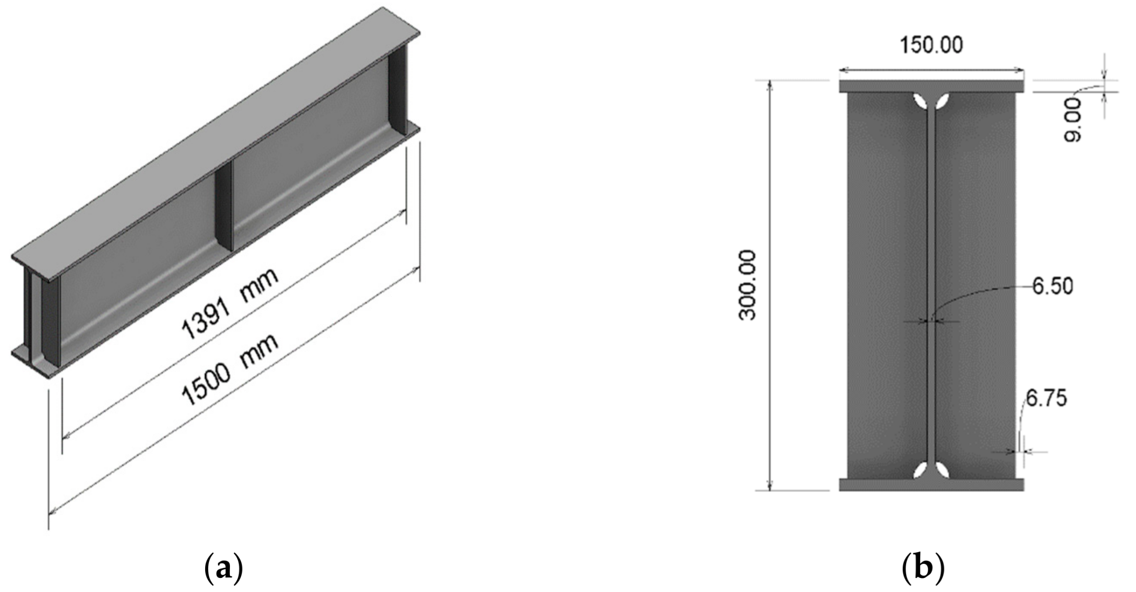
2.1. Specimen Properties

In the current research, a dog-bone experiment was performed on the steel material of the experimental H-shaped beam to evaluate the material properties of the steel. The Japanese Industrial Standards (JIS) were used to determine the sizes of the specimens. Four specimens’ dimensions were of the original beam section that was originally used to prepare the experiment beams, as per Figure 1a. They were cut off the beam flange top and bottom and two directional strain gauges were placed on the two faces of the specimens to evaluate the values of modulus of elasticity and Poisson’s ratio, as shown in Figure 1b.

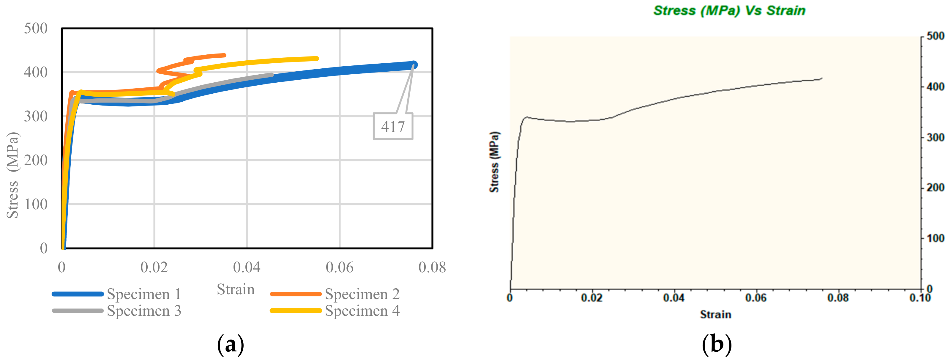
2.2. Material Test Results

The results of the four specimens are plotted in Figure 2a. Upon observing the plot, it is evident that specimen one exhibits superior behavior compared to the other specimens. The strain values in specimen one surpass those of the other specimens until the dog-bone specimens fail. In contrast, specimens two, three, and four do not yield accurate results and do not reach the plastic deformation stage, unlike specimen one. Specimen one demonstrates higher and more favorable strain values than the other specimens.
Consequently, the results from specimen one were utilized to estimate the values of the steel material’s modulus of elasticity, yielding stress, and tensile stress. Specimen one begins experiencing plastic deformation at the clouded region for strain values from 0.01 to 0.02, as per Figure 2a, which corresponds to an approximate stress value of 333 Mpa, known as yield stress. Figure 2b illustrates the slope of the linear line, representing the modulus of elasticity, with a value of 195 GPa. Additionally, the tensile stress at which specimen one fractures is 417 MPa, as depicted in Figure 2b. These obtained results were subsequently inputted into the finite element analysis software used in this study, specifically the Inventor Nastran 2023 program. Figure 2b showcases the stress–strain curve derived from the final curve data of specimen one, which was inserted into Nastran to simulate the material behavior during the analysis, particularly the three-point bending test.

3. Finite Element Analysis for Three-Point Bending Test

3.1. Description of the Experiment Beam

The three-point bending test serves as an optimal method for evaluating the accuracy of the finite element analysis (FEA) for both prototypes: one with bonded CFRP layers and one without CFRP strengthening. The test allows for assessing the capacity of the beam in its original, unenhanced state, without any applied enhancements or retrofitting methods. The steel section used has dimensions shown in Figure 3a,b. Three stiffeners are fillet welded on each side of the beam.
Two stiffeners are placed in the middle of the beam, while two additional stiffeners are positioned on both sides, in both the left and right directions. The edge distance from the middle of the stiffener is 50 mm, and the stiffener itself has a thickness of 9 mm and a setback of 6.75 mm. The total length of the beam is 1500 mm, with a clear span of 1391 mm from the inner face of the right stiffener to the inner face of the left stiffener.

3.2. Finite Element Model with No CFRP Laminate
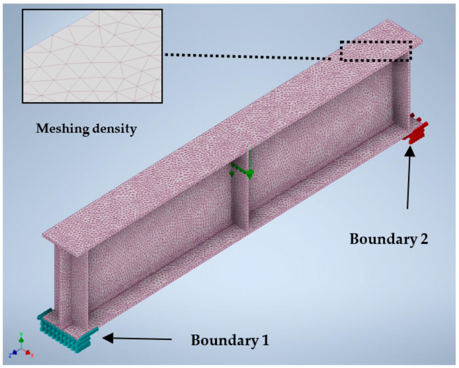
The finite element model was prepared through a 3D model on Revit 2022 software, then it was exported to Nastran where the preparation of the model was based on the following mentioned steps in the upcoming sections.

3.2.1. Meshing

The meshing technique used was parabolic meshing. Parabolic meshing utilizes higher-order elements, such as quadratic quadrilaterals (eight nodes), which was used for the shell element to model the laminate of CFRP and parabolic tetrahedrons (ten nodes) for the solid part of the steel beam, which has higher-order shape functions. Parabolic meshing generally provides better accuracy and more precise representation of the geometry compared to linear meshing, especially for curved or complex geometries, which match the case of the girder as it has both complex and curved shapes. The mesh size chosen was 20 mm for the whole beam, except for the bottom flange, which was set to 15 mm to give more accurate results in the comparison between the numerical model and the experiment prototype, as shown in Figure 4. The coordinates of the model were set to be Y for vertical direction and XZ-plane to be the plane coordinates. Figure 5 arrows 1, 2, and 3 refer to the rotation in Y, X, and Z directions, respectively.

3.2.2. Supports and Loading

The beam is supported with two boundary conditions. Boundary one is free to move in the Z direction and free to rotate around the X direction while boundary condition two is only free to rotate around the X direction. The load was applied in the middle to match the loading criteria for the three-point bending test.

3.2.3. Contact Type

In Nastran, a distinctive method is available to define the contact type between surfaces, which allows for simulating connections between different surfaces, such as stiffeners and beams, as well as flanges and web surfaces. The chosen option for the contact type was “bonded.” This contact type represents an interaction between surfaces or bodies where they are intended to remain in continuous contact, mimicking the behavior of bonded interfaces or contact regions that resist separation. By selecting this contact type, the simulation aims to capture the structural effects, simulating the conditions encountered during welding on the beam.

3.3. Finite Element Model with CFRP Laminate

The FEA for the CFRP laminate condition was established in the same way as the regular model was created with the addition of the CFRP meshing and laminate properties. The CFRP laminate was assigned to the face of the bottom inner flange (tension side) and to the face of the stiffeners with a shell element and another meshing (orange mesh) was added to form continuous meshing with the face of the solid beam, see Figure 6a, then a laminate was assigned to the mesh part in addition to the material orientation, which indicates the alignment of the material parallel to the direction of the beam surface. The meshing of the shell element represents the CFRP laminate over the beam surface (Figure 6b); also, in Figure 6c, the purple meshing before applying the CFRP laminate mesh in orange is seen. In Figure 6b, we can see the corner type of the CFRP within the intersection point between the stiffener part and flange. The CFRP laminate consists of three layers of high-strength CFRP with a product number (UT70-30G) and epoxy E2500 to attach the sheets to the beam surface. E2500 has a modulus of elasticity of 4.1 GPa in addition to a Poisson’s ratio of 0.37. The carbon fiber sheets properties, as provided by the manufacturer, are as follows: tensile strength value of 3400 MPa and modulus of elasticity 230 GPa, in addition to a thickness of one layer equal to 0.167 mm. The CFRP layers’ properties were computed using a composite lamination rule within the following Equations (1)–(4), where Ex indicates the longitudinal elastic modulus and Ey is the transverse elastic modulus of the CFRP layers.
Gxy is the shear modulus value of the composite CFRP sheet. v f = 0.3 is the content of carbon fiber and v m = 0.7 is the content of matrix (epoxy) in CFRP layers. Ef and Em are the values of the elastic modulus of the carbon fiber and epoxy content in CFRP laminate layers, respectively; tf refers to the thickness of the fiber sheet according to the manufacturer’s sheet, tm refers to the thickness of the mattress calculated from Equation (4), and tcf refers to the final measured CFRP laminate after the final molding process. Table 1 shows the calculated values of all the CFRP properties. The CFRP sheets were molded using the hand lay-up molding method, as shown in Figure 7.
E x = v f E f + v m E m
G x y = 1 v f G f + v m G m
E y = 1 v f E f + v m E m
v f = t f t c f , v m = t m t c f ,   t c f = t f + t m

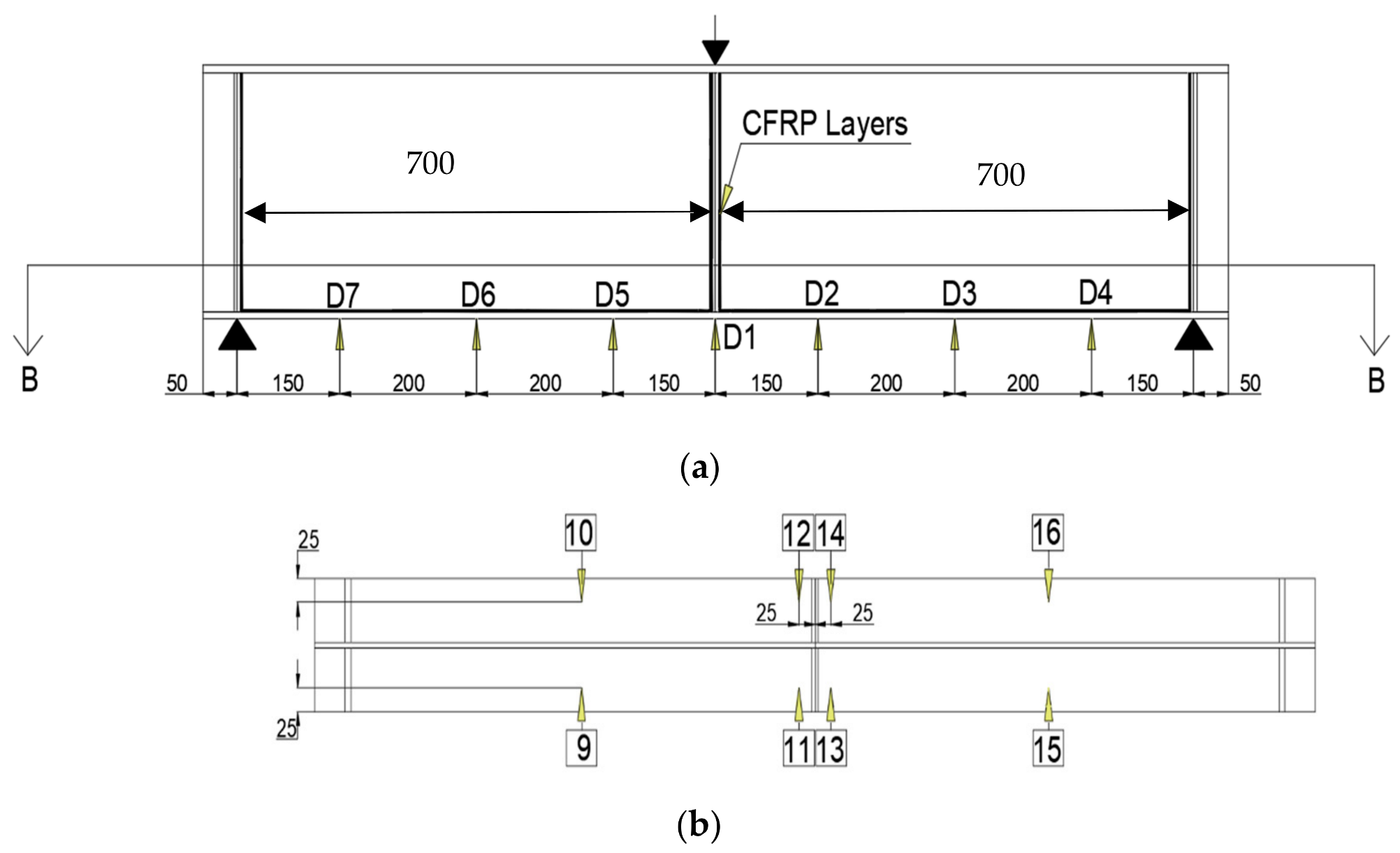
4. Experimental Setup for a Three-Point Bending Test

4.1. Experimental Setup of Strengthened and Un-Strengthened Conditions

The machine used for the experiment was the MAEKAWA testing machine (MFG. CO. LTD. WAC-200-B1), as shown in Figure 8. The two-beam experimental setup consists of two supporters (A) and (B) on the sides both right and left, and a rolled metal at the center of the top of the beam that acts on the beam as the primary load during the experiment. The middle stiffener on each side is aligned with the center of the supporter to avoid any eccentricity. The displacement transducers were placed on seven different points in the span direction (longitudinal) for both specimens. The strain gauges were placed along different locations of the beam then the results of the strain gauges values obtained from experiments were compared with the finite element results and showed good matching results in the bonded and unbonded beam conditions. As a result, the FEA method can be used to analyze the girder behavior under bending loads and the strengthening effects of CFRP layers on the girder behavior to study the impact of using CFRP layers on the load-carrying capacity of the beam.

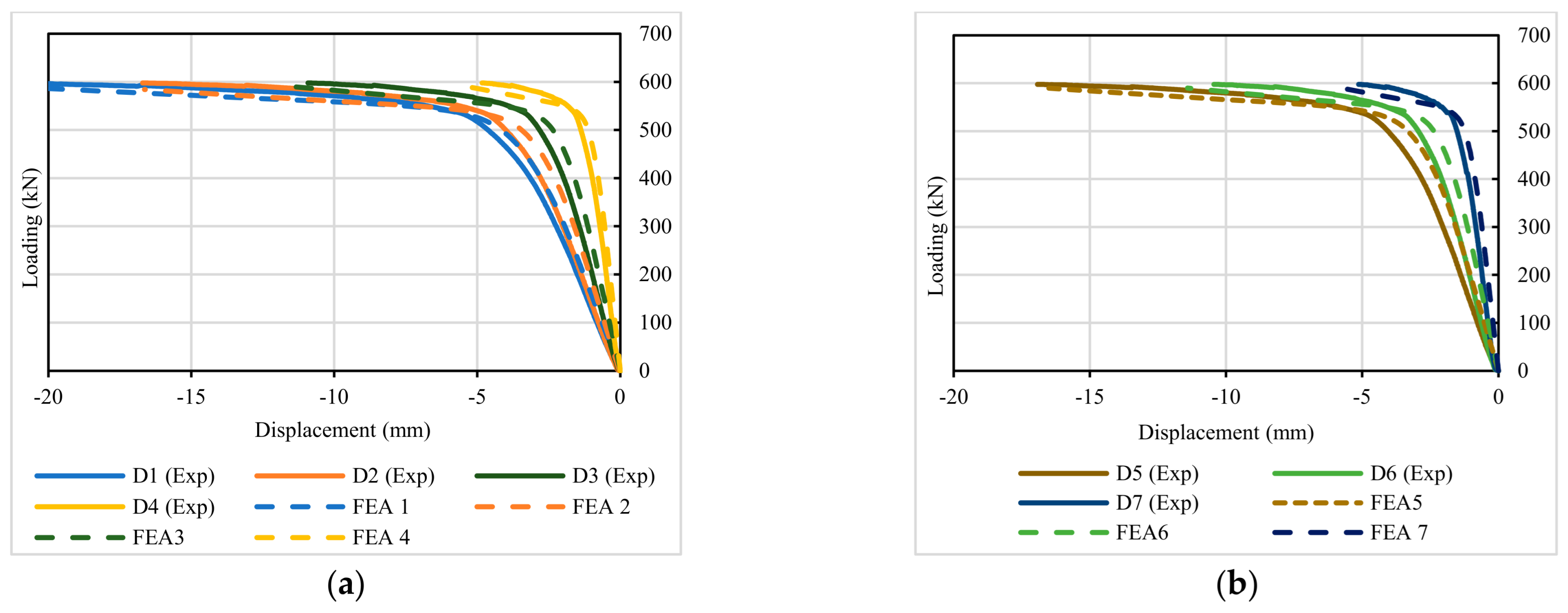
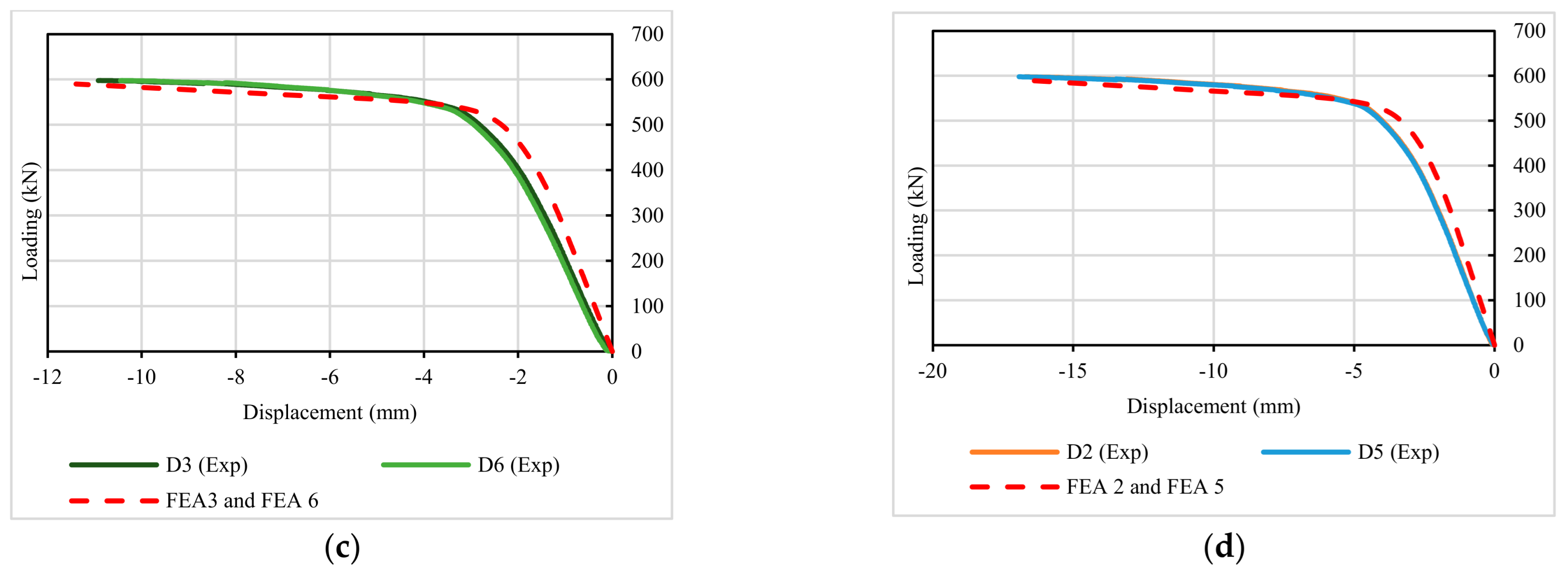
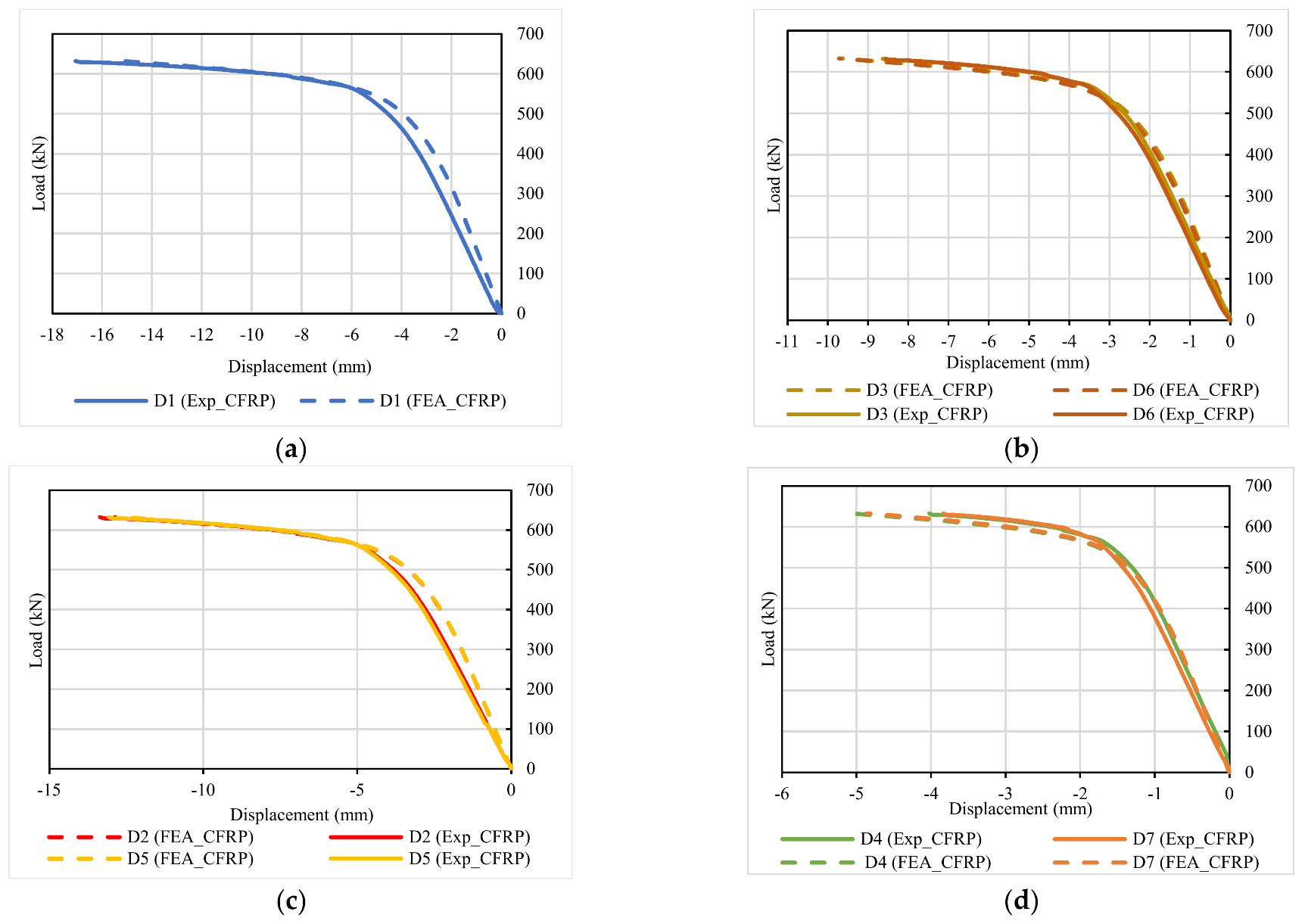
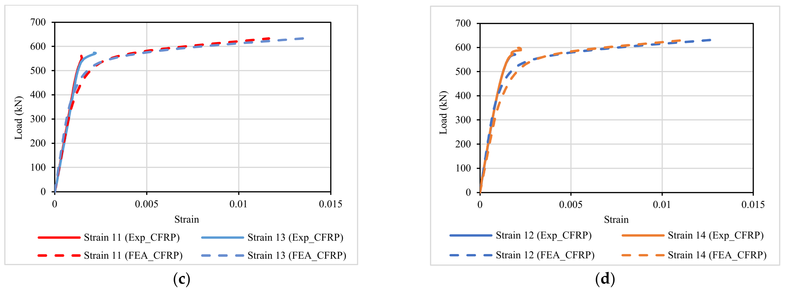
4.2. Load–Displacement and Load–Strain Relation Results

The positions of strain gauges and transducers were placed among the beam for the un-strengthened beam where the numbering of strain gauges ranges from (1) to (8) and from D1 to D7 for transducers, as shown in Figure 9.
The positions of strain gauges and transducers for the strengthened beam are shown in Figure 10. The numbering of strain gauges range from (9) to (16) and from D1 to D7 for transducers, plus the placement of the CFRP along the inner bottom flange with the stiffeners on both sides of the beam span.
Figure 11a,b show the comparison of load–displacement relations of un-strengthened specimens in the experiments (continuous lines) and the FEA (dashed lines). The graph shows a great resemblance between both results, especially in the plastic stage, which gives creditability to using the same method and criteria to evaluate the behavior of the girder beam.
Figure 11c,d show the comparison of load–displacement between FEA and the experiment of D2 with D5, and D3 with D6 points. This comparison provides insight into the behavior of the flange on both sides of the beam and indicates that the beam has symmetrical behavior in the middle of the span on two sides of the beam with slight differences between each other due to the imperfection of the beam geometry.
However, this imperfection is a complex process inside the Nastran model, since the software has a limitation of running a consecutive type of analysis since it allows only for the running of one type of analysis at a time, which is the nonlinear analysis. In Figure 12a,b, we can see the comparison between strain gauge points from the experiment and the FEA for the same un-strengthened beam. The results are almost identical in the elastic stage and plastic stage as well.
Figure 13 show elastic and plastic behaviors of load–displacement relations in the strengthened beams in the same positions as the un-strengthened beam. The comparison between the experiment (continuous lines) and FEA (dashed lines) is plotted in the graphs where some differences can be seen in Figure 13c,d due to the limitations of assigning imperfection to the geometry of the beam, resulting in a higher displacement in the elastic stage noticed near the beam supports where a stiffener was fillet-welded on both sides of the beam.
The graph in Figure 13b–d illustrates that points D2, D3, and D4 are mirror images of points D5, D6, and D7, respectively. While these points show similar results, they are very close to the experimental data. Figure 14a,b present the load–strain relationships of strengthened beams at positions 9, 10, 15, and 16, which are in the middle of the strengthened beam. These graphs depict both elastic and plastic behaviors.
A comparison is made between the strain gauge readings obtained from the experiment and those obtained from finite element analysis (FEA). The results indicate a strong correlation between the experimental and FEA data in graphs Figure 14a,b, up until the observed debonding occurs at approximately 550 kN and 580 kN in Figure 14a,b, respectively. However, the FEA data continue beyond 600 in both graphs. Figure 14c,d show higher variations, as the experimental beam debones at a load of approximately 580 kN in both cases.
These differences can be attributed to the difficulty of accurately modeling debonding in the FEA, even though the strain gauge readings from the experiments closely match the elastic behavior of the CFRP sheets.
Moreover, the discrepancies seem to be concentrated near the middle stiffener, which is directly under the load. This suggests an unnoticed debonding that causes the strain gauges to stop recording data after the debonding load.

4.3. CFRP Strengthening Effect

The debonding of the CFRP on the beam occurs only on one side of the middle stiffener, as shown in Figure 15a and Figure 16a. The remaining sections of the beam do not show any signs of debonding until failure, which is consistent with the shear stress on the beam for the FEA element compared to the experiment shown in Figure 15b and Figure 16b.
The results suggest that due to the occurrence of buckling on one side of the beam, the stresses are concentrated on one edge of the beam, resulting in debonding on the middle stiffener. This can be observed in Figure 16a, where the stiffener is suffering from buckling on one side, compared to Figure 15a, where the stiffener does not buckle. Therefore, it can be concluded that the buckling of the beam causes the stresses to concentrate on one edge, leading to debonding on the middle stiffener.
Moreover, when comparing the maximum displacement of the beam before and after strengthening, as illustrated in Figure 17, it can be observed that the beam exhibits an improvement of 8–10%. Specifically, the maximum bearing load increases from 597.78 kN to 632.58 kN, representing an improvement of 5.83% to 10.48%. Furthermore, the maximum displacement at approximately the same amount of load decrease from 21.51 mm to almost 9.00 mm, indicating an improvement of 57% in displacement behavior.

5. Steel Girder Numerical Model

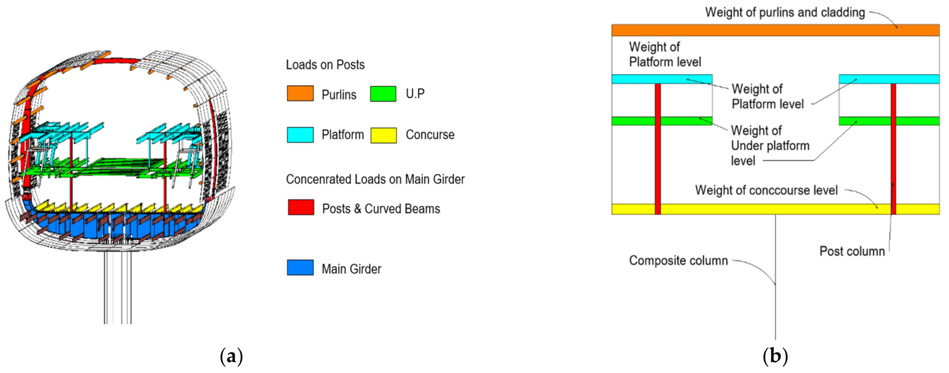
5.1. Loads Calculation

The loads were calculated according to the specifications for live load values and the weight for dead load types including the finishes weight, the block weights, and the electric cables weights with fixings. The BIM model made on Revit software for the metro station was used for the accurate calculation of dead load elements. BIM models include the mechanical, electrical, plumbing (MEP) elements that gives the accurate length of electric trays carrying the electric cables and the architectural BIM models are used for the calculation of area finishes in addition to block work lengths and weights. These were all considered dead loads acting over the beams for each level. The steel structure model gave an accurate calculation of steel beam weights in addition to the area of the concrete slab. The architecture model also provides the area and the weight of the cladding that surrounds this part of the station in addition to the ceiling and the suspension system, as can be seen in an example of the calculated weights of steel beams of the concourse level in Table 2.
Platform levels includes steel beams with connections and finishes. The under-platform level includes the steel beams with connections plus the ceiling suspension system in addition to stairs. The concourse level includes the concourse level steel beams with connections that also prevent the lateral torsion of the main girder. The main girder statical system is loaded with two posts in the first two-quarters of the span. The carried loads come from both platform levels and under the platform level, and are on the edge of the beam. There are the side girders that carry the loads coming from cladding as seen in Figure 18 and Figure 19a and purlins that also play a vital role in supporting this part of the station from lateral movement. The statical system is represented in Figure 19a,b. The loads for each part can be counted as follows for each part:
The weight of purlins is counted from the BIM model similar to Table 2, in addition to cladding weight estimated based on the surface area and the cladding density. The weight of the platform level is counted based on the steel beams and connections weight plus finishes. The weight of the under-platform level is similar to the platform level, and is calculated by calculating the weight of steel beams and connections plus the beams that carry ceiling and electrical cables in addition to the finishes.
The concourse level weight is calculated through the weight of concourse level beams and connections in addition to the finishes level and live load. All levels with rooms have additional loads of brick walls in addition to equipment and escalators in case any of them exist within the area of the study since it is only made on one girder, and the surrounding spans only are calculated for all these levels.
The self-load of steel beams weights was increased by 25% to mimic the connection and the painting loads. To examine the effects of increased loads on the yield stress and assess the impact on the girder parts, the final calculated loads were amplified by 10%. Additionally, the influence of using a CFRP laminate sheet on the beam was studied. Figure 18 illustrates the section of the station, highlighting the main girder in blue, which serves as the focal point of the study and undergoes varying levels of loading. This analysis allows for a comprehensive understanding of the structural response and the benefits provided by the CFRP laminate.

5.2. Finite Element Steel Girder Model Set Up

A half model with symmetrical boundary conditions was used for the steel main girder in the Nastran 2023 software to reduce the number of meshes and analysis time. The total length of the beam exceeded 20.00 m, and a symmetrical constraint was applied at the middle of the beam, where the split segment was created. The detail of the model is described in the next part.

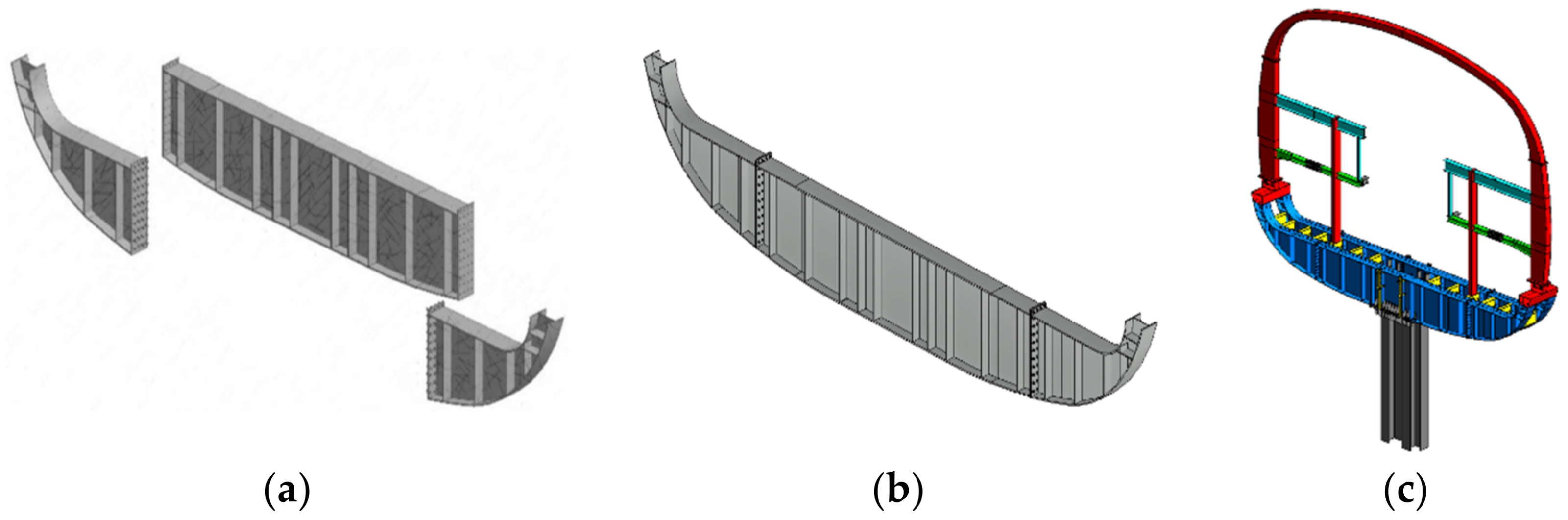
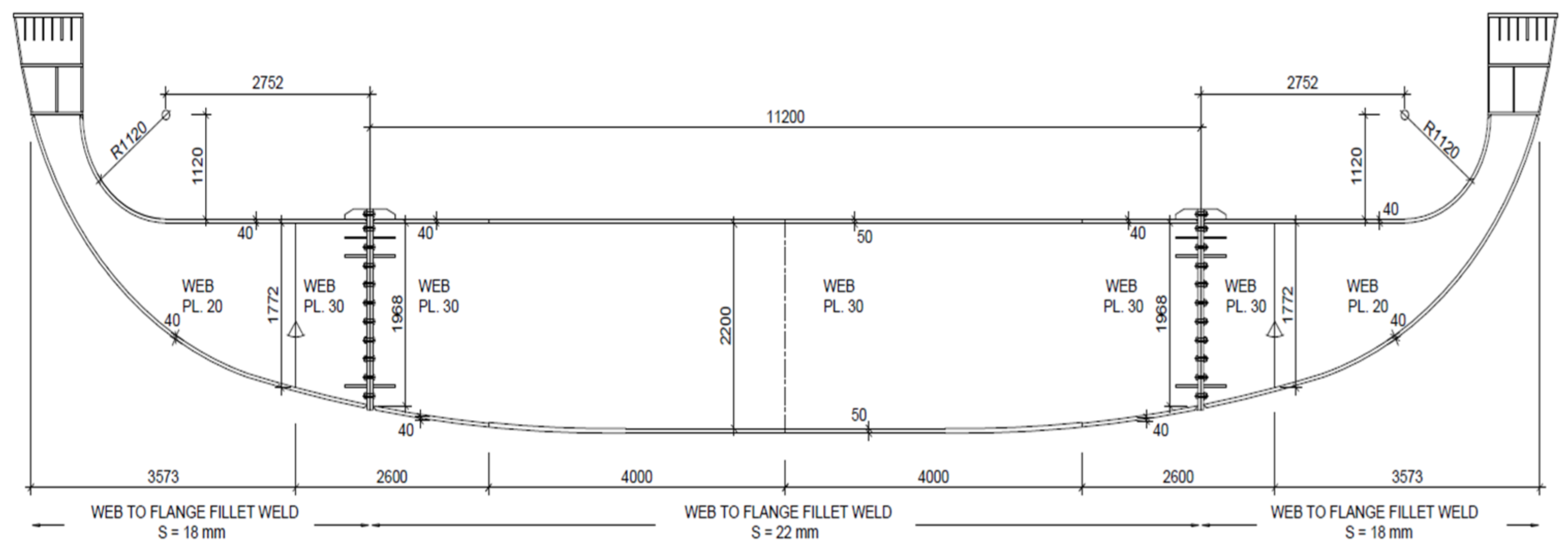
5.2.1. Description of the Model

Figure 20a shows the main girder parts and Figure 20b shows the assembled parts together that were modeled for the analysis, while Figure 20c shows the girder integration with the rest of the steel frame elements. The girder consists of a series of plates that form the flange, welded to both the top and bottom fillet along with a web plate. Additionally, there are several stiffeners attached to the beam along its span, using the same type of welding. These features are replicated in the finite element analysis (FEA) by applying bonded contact between surfaces, which is typical for the FEA model used for the experimental beam. The beam is rested mainly on a composite column that consists of a steel column with the casting of concrete right in the middle of the beam. The girder is divided into three parts, two of which are on the right and left bolted to the middle part, and this has an assembly that differs based on the construction sequence based on the location of the girder. Figure 21 shows the full dimensions of the girder with the position of welding and its type and thickness between the web parts and flange parts on top and bottom in addition to the thickness of flange segments, which is 40 mm on the sides and 50 mm in the middle and the thickness of the web is 20 mm and 30 mm on the side and the middle, respectively.

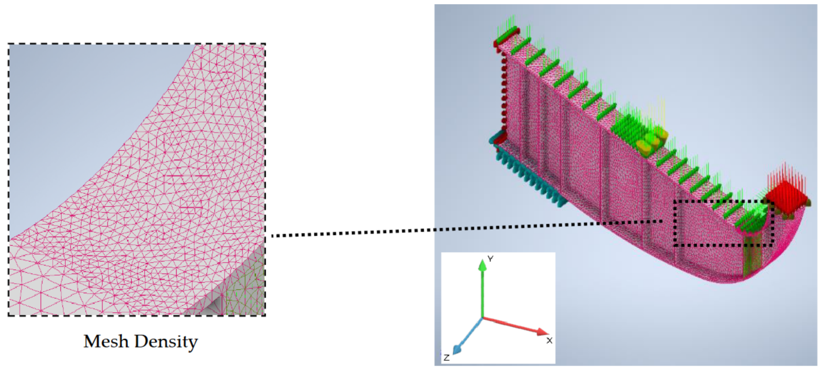
5.2.2. Meshing Description

The applied meshing technique on this model is similar to the one used in the three-point bending test. The meshing types used were parabolic tetrahedrons. These have 10 nodes and are excellent general purpose elements suitable for most applications. This meshing type gives more accurate results in the case of curvature shape, which is suitable here with the curvature of the beam. The mesh size chosen is 75 mm, since the size and the span of the girder are almost 10 times the size of the beam prototype that is experimented on.
The coordinates of the model were set the same as the experimental beam finite element of Figure 5 to be Y for vertical direction and XZ plane to be the plane coordinates. The girder was divided in half since it is symmetric to reduce the total number of meshes in the model and reduce the run time analysis. The symmetrical condition was applied to the cut face as presented in the next section.
In Figure 22, the meshing of the girder is shown where the whole girder has a 75 mm mesh size over the whole girder while the curved part is mesh with a smaller size mesh of 20 mm for better accuracy of stress representation.

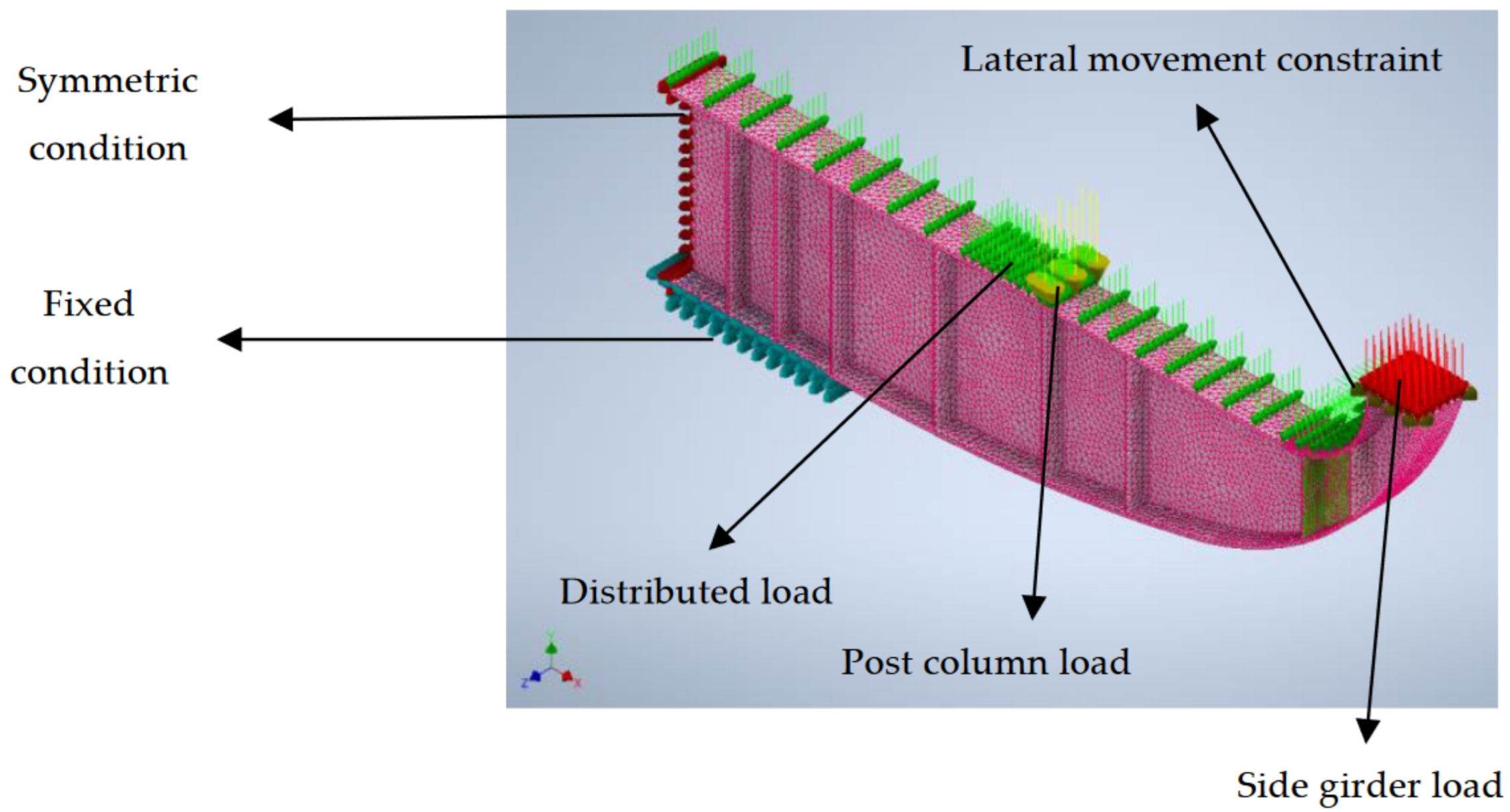
5.2.3. Supporting and Loading Conditions

There are three types of constraints applied in the girder model presented in Figure 23: symmetric condition to simulate the full size of the girder with free movement in both Z and X directions in addition to free rotation in the Y direction. The fixed condition simulates the column support condition with fixed movement and rotation in all directions (Z, X, Y). The lateral movement is applied near the edge to prevent the girder from lateral movement in Z and X directions since it is supported by side purlins.
The applied load on the girder varies from the distributed load that comes from the concourse level to the post load, which transforms the platforms and platform’s loads to the girder in addition to the side girder load, which carries the rest of the frame that carries cladding of the station all calculated from Revit, as in Table 2 that shows the weight of the concourse level beams.

5.2.4. Girder Steel Properties

The steel used for the girder has a modulus of elasticity of 210,000 MPa and a Poisson’s ratio of 0.3. These properties were inserted into the properties of the finite element model where a nonlinear ‘elasto-plastic (bi-linear)’ material, as per Figure 24, was used since it is hard to obtain the properties based on a specimen from the actual steel girder. In this method, the plastic region can be defined by a plasticity modulus (H) equal to 23.33 Mpa. The plasticity modulus (H) is, in turn, related to the tangent modulus ( E T ) and Young’s modulus ( E ) as per Equation (5).
The value of tangent modulus ( E T ) is set to 10% of Young’s modulus as a default, thus, the default values ensure a 10% slope for the linear plastic part of the material’s stress–strain curve. Inventor Nastran calculates the stress values by linearly extrapolating outside the table and linearly interpolating inside the table based on the last two endpoints of the curve. Since the steel type is EN 10025, Gr.S355 the material yield stress is assumed to be 355 MPa based on the material properties.
H = E T 1 E T E

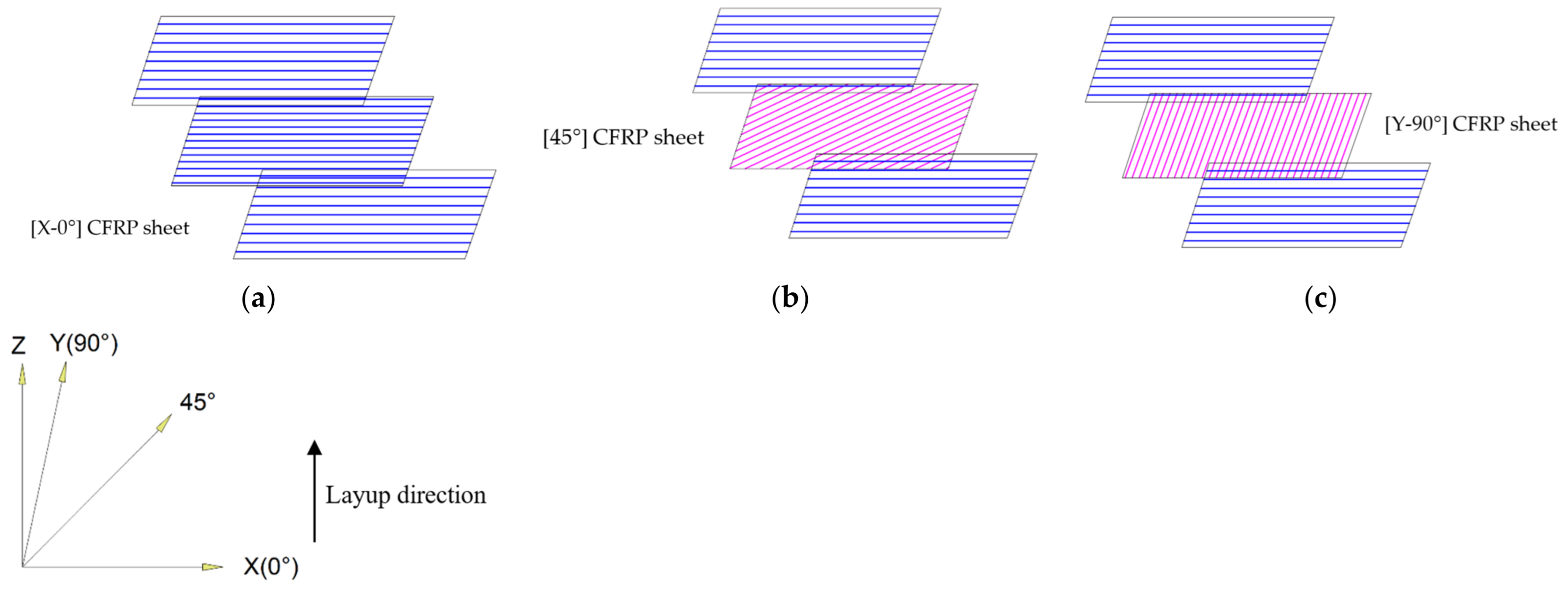
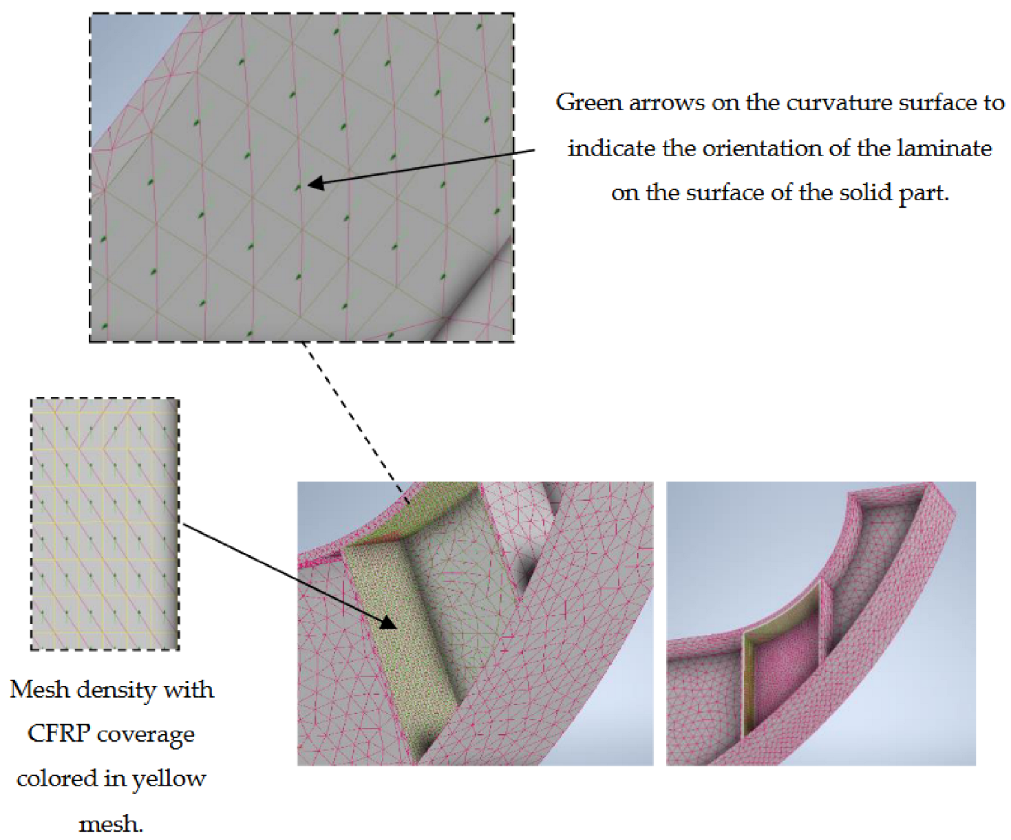
5.2.5. Composite Material Definition and Assigning

CFRP layers with a product number (UT70-60G) were assumed to strengthen the girder to obtain thicker and sustain higher stresses with a smaller number of CFRP layers. The carbon fiber sheets properties, as provided by the manufacturer, are as follows: tensile strength value of 3400 MPa and modulus of elasticity of 230 GPa for civil engineering type, in addition to a thickness of one sheet equal to 0.333 mm. These sheets are bonded into the steel surfaces of the girders by E2500 adhesive. The properties of CFRP layers properties were calculated according to composite lamination rules with Equations (1)–(4) used in the experiment beam. v f = 0.3 is the content of carbon fiber and v m = 0.7 is the volume content of matrix (epoxy) in the CFRP layers. Table 3 shows the calculated values for each parameter. The thickness of one layer is computed by dividing sheet thickness by the fiber volume vf. For the CFRP laminate of thickness 19.97 mm, 18 layers were used, while 22 layers were used for 24.22 mm thickness; however, it was only applied for [0°] to investigate whether is a dramatic change in the stresses in case a few additional layers were added to the laminate, as per Figure 25.
The process of assigning the shell element with CFRP material is similar to the process used with the experimental beam. However, in the case of the girder, there are different alignment options to be tested, such as [0°], [0°–90°], and [0°–45°], which are provided by Nastran and follow the theory of classical laminate theory. This theory assumes that the laminate is made up of an infinite number of thin layers, each of which is perfectly orthotropic. The layers are then stacked on top of each other, and the properties of the laminate are calculated as a function of the properties of the individual layers and their stacking sequence.
According to Figure 25, the laminate is formed by the duplication of CFRP sheets with each with the tested angle. However, it is noticed that the beginning of each laminate in the case of bi-directional laminates that [0°] sheets are the first sheet on the steel beam surface and the different angle whether [90°] or [45°] is the one next to it, which results in making the different angle as the last sheet of the laminate.
When aligning CFRP on beams, the [0°] is considered as the first and last layer for different thicknesses, while the middle layers alternate between [0°], [45°], and [90°], depending on the applied method. The arrangement of the CFRP sheets in the global coordinates is illustrated in Figure 26. Figure 26a shows the typical arrangement of the 0° laminate with a consistent direction of the layup.
Figure 26b depicts the typical arrangement of the [0°–45°] laminate. Figure 26c showcases the typical arrangement of the [0°–90°] laminate. These sheet arrangements are replicated throughout to achieve a required thickness of 19.97 mm and 24.22 mm for applying right on the surface of the solid geometry, which represents the steel girder.
The nonlinear analysis shows that the curved part of the girder has the largest stress over the tension part of the beam, although the stresses over the middle part were not uniform in the case of the un-strengthened girder since it has the largest stresses. Therefore, these parts were strengthened with CFRP laminate layers.
Since the girder has a metal deck over the beam, it is optimum to apply the CFRP laminate on the inner side of the flange shown in Figure 27. The previously mentioned and defined CFRP laminates were applied on the inner side of each stiffener, and the inner side of the flange through the shell element that carries the properties of each laminate depending on each case, so that the shell layers cover the solid element of the steel girder to form continuous meshing, as presented in Figure 27. The yellow color refers to the shell element of the CFRP laminate and the purple meshing refers to the solid element, which has the steel girder properties only.

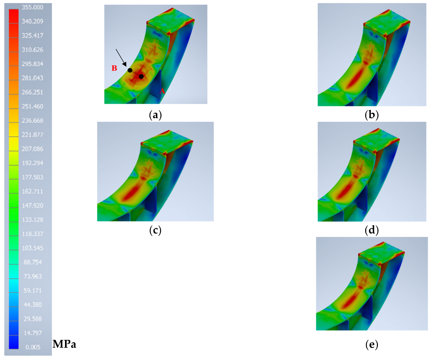
5.2.6. Results and Comparison

Different types and thicknesses of CFRP sheets were used and tested in the FEA to investigate the percentage of improvement measured by the reduction in the von Mises stress value. It is notable that the reduction in stresses is higher in the case of increasing the thickness of all layers (18 layers) with a total thickness of 19.97 mm and 0°alignment, while the reduction in stresses in the cases of the same degree and higher thickness of 24.42 mm is much higher. Other alignments were tested, [0°–90°] and [0°–45°], with a thickness of 19.97 (18 layers) of the CFRP sheets, which gave similar or close results to the [0°] alignment with the same thickness.
Differences between the stresses before and after strengthening can be seen in the clouded part for each case in Figure 28a–e and it is noticeable that stress formation has gained some uniformity and more regular distribution after the usage of the CFRP laminates. The diagram of stresses along the line segment can be seen in Figure 29 and a comparison of the stress reduction percentage over that line segment is plotted in Figure 30.
The calculated von Mises stresses are for the calculated loads, with an increase of 10% to mimic a future increase in loads and to study the effect on the steel girder part after reaching the yield stress. The effect of using different layers of CFRP of varying thickness and alignment on the structural behavior of girders is an important area of research. In this regard, Figure 28 displays several graphs that showcase the impact of using various types of CFRP layers on the von Mises stress distribution within the girder. In Figure 28a, it is evident that the girder suffers from unbalanced stress distributions over the curved part, although the higher stresses are in the middle of the curved part. Figure 28b shows the application of CFRP layers [0°] arrangement where the stresses are reduced. It is similar to the stresses contour for the rest of the arrangement, although it is not as big as the [0°] alignment, resulting in a reduction in von Mises stress. Interestingly, when comparing the results for CFRP layers 24.4 mm and 19.97 mm thickness, both provide similar stress reduction for the [0°] alignment. Additionally, it is noteworthy that the same layers are not used over the web of the girder, yet the stress reduction is significant. Figure 28c–e show the stress distribution for different layers in [0°–90°], [0°–45°], and [0°] arrangements, respectively, except that Figure 28e shows a bigger thickness than other layers. This is to investigate the effectiveness of increasing the thickness of the laminate on the stress distribution, and shows a reduction in stresses represented in the contour lines. Figure 29 shows a comparison of stresses over the line segment A–B for all applied cases. Starting with the un-strengthened girder, it can be noticed that the distribution of stresses does not suffer from irregularity: the stresses near the distance where the web of the girder has contact with the flange is reduced compared to the stresses before and after the distance between 200 mm and 150 mm. Furthermore, Figure 30 demonstrates the reduction percentage in von Mises stresses for each case. The yellow color for the biggest thickness (24.42 mm, 60% of the flange thickness) for the [0°] arrangement has the biggest reduction percentage, at almost 20 % as maximum and 12 % as an average percentage, which is the targeted value followed by 19.98,50% of the flange thickness for the same arrangement. However, using the [0°–45°] arrangements results in a better reduction percentage than the [0°–90°] reduction percentage, even though both are lower than the [0°] arrangement. It might be advisable to use the [0°–45°] as a bidirectional layer to prevent de-bonding [4] and increasing the thickness of [0°–45°] thickness to the 60 % means a bigger percentage reduction, since the 50 % [0°–45°] gave an average reduction of 10%.

6. Discussion

This study present a novel investigation into the application of a CFRP laminate on the inner surface of a flange, considering different layer arrangements and thicknesses. This approach aims to enhance the load-carrying capacity of the flange for extended service life, and to the best of our knowledge, no similar method has been reported in the literature. In addition to its technical benefits, the application of a CFRP laminate on the inner side of the girder offers practical advantages. This approach does not cause any destruction to the surface finishes, eliminating the need for extensive repair or rework. Moreover, it avoids the disruption of activities within the facility where the girder is located. Given the heavy and continuous use of such facilities, it is essential to minimize stoppages or closures. By utilizing the CFRP laminate on the inner side of the girder, the serviceability of the girder can be enhanced without interrupting the normal operations of the facility. This technique provides a practical and effective method for increasing the load-carrying capacity and extending the service life of the girder, while ensuring the uninterrupted functionality of the facility.
The study provides valuable insights into the optimal molding of CFRP laminates and recommends FEA practices to ensure consistency between experimental and FEA outcomes. Additionally, an FEA analysis was conducted on the girder to achieve the desired stress reduction by adjusting the number of CFRP layers relative to the flange thickness.
In addition to the novelty of the study, the application of building information modeling (BIM) models in load determination and inspection of the existing structural system of the girder is highlighted. The use of BIM streamlines the process compared to traditional methods, and its widespread use in early design, coordination activities, and structural analysis further emphasizes its significance in this context.
The results demonstrate that augmenting the thickness of CFRP layers results in a greater reduction in von Mises stress values within the steel girder. This finding aligns with previous research, confirming the efficacy of CFRP laminates in reducing stresses and enhancing the load-carrying capacity of steel beams [8]. The examination of various layer arrangements and thicknesses of CFRP sheets provides valuable insights. Notably, the [0°] alignment, when combined with increased thickness, exhibits the most significant stress reduction, indicating its effectiveness in bolstering the load-bearing capacity of the steel girder. Moreover, the utilization of bidirectional layers such as [0°–45°] serves as a preventive measure against debonding and can be deemed an effective approach [4]. Although the FEA does not reveal signs of debonding, it is important to acknowledge its potential significance in practical applications. Further investigation is warranted to determine the optimal arrangement and thickness of CFRP layers, aiming to achieve maximum stress reduction and structural enhancement. The study emphasizes the importance of employing proper surface preparation techniques to establish robust CFRP–steel joints. While surface preparation does not significantly affect specimen stiffness, it plays a critical role in joint strength. Notably, the experimental beam does not experience substantial debonding, except for localized buckling around the middle stiffener. This underscores the significance of appropriate surface preparation in attaining a reliable bond between CFRP and steel [23]. Future research could focus on the predictability of debonding using Inventor Nastran’s approach and the modeling techniques. Nevertheless, it is essential to acknowledge the debonding limitations of the FEA employed in this study. The analysis encountered challenges regarding meshing size when applied to the entire girder, resulting in increased analysis time. Furthermore, the ability to assign imperfections to the girder model was limited, which may impact the prediction of girder behavior and the correlation between FEA and experimental outcomes, particularly in the context of the three-point bending test. Future research endeavors could explore improved meshing strategies and more precise representation of imperfections to enhance the accuracy and efficiency of FEA models in predicting the behavior of CFRP-strengthened steel beams. In addition to the investigation of CFRP strengthening, this study also highlights the significant advantages of using Inventor Nastran 2023 as the finite element analysis (FEA) software. Unlike other FEA software, Inventor Nastran demonstrates remarkable flexibility in modeling irregular and curved shapes, which are commonly encountered in complex structures. This software surpasses its counterparts by offering advanced meshing techniques that simplify the assignment of meshes to the entire geometry, including the ability to assign different mesh sizes to specific areas. This feature not only streamlines the modeling process but also saves valuable time.
Furthermore, the integration of building information modeling (BIM) models into Inventor Nastran provides a substantial advantage in terms of modeling efficiency. This capability allows for the utilization of existing models, which is particularly advantageous when working with large-sized shapes or structures. The contact features within Inventor Nastran also contribute to its versatility. They enable the handling of various types of connections between different geometries and surfaces, offering a range of options depending on the desired connectivity. In the current study, these contact features were utilized to model welded surfaces. However, their flexibility and adaptability make them applicable to future research involving different types of connectivity. Additionally, the software’s intuitive design and features facilitate the process of specifying and adjusting the CFRP laminate thicknesses, allowing for easy experimentation with different configurations. This capability enables researchers and engineers to investigate a wide range of CFRP strengthening possibilities in future research and evaluate their respective impacts on the load-carrying capacity of steel girders.
Overall, the combination of the CFRP strengthening investigation and the utilization of Inventor Nastran as the FEA software presents a comprehensive approach for analyzing and enhancing the load-carrying capacity of steel girders in metro stations. The study demonstrates the potential of CFRP and highlights the advanced capabilities of Inventor Nastran, including its flexibility in modeling complex shapes, efficient meshing techniques, BIM integration, and versatile contact features.

7. Conclusions

This study investigated the strengthening effect of CFRP layers on steel main girders under bending loads through experimental and numerical analysis. The use of CFRP strengthening on the tensioned flange’s side section of the girder was found to be an optimal method for retrofitting and reinforcing the beam’s tension side. This approach proves to be a viable alternative to strengthening the outer side of beams, particularly in challenging construction conditions. The strengthening effect ranges from 8%–10% in the whole sections, and up to 19% in the center of the CFRP strengthening positions
To achieve a significant reduction in stresses, the total thickness of the CFRP layers should be at least 50% of the total thickness of the flange. Increasing the thickness beyond 50% leads to a higher reduction percentage of up to 5%. The use of the FEA software Nastran for girder investigation was validated, emphasizing the importance of having accurate stress–strain curves for the material to obtain precise results, especially beyond the yielding stress.
The application of a CFRP laminate on the inner side of the girder offers practical advantages, including no destruction to surface finishes, avoidance of disruptions in facility activities, and enhanced serviceability of the girder without interrupting normal operations. The study provides valuable insights into optimal CFRP laminate molding and recommends using BIM models for load determination and inspection of existing structural systems. The results demonstrate that increasing the thickness of CFRP layers and using specific arrangements can significantly reduce von Mises stress values within the steel girder, improving its load-carrying capacity.
However, it is important to acknowledge the limitations of the study, including potential debonding and challenges in meshing size and assigning imperfections in the FEA analysis. Further research is needed to determine optimal layer arrangements and thicknesses, predict debonding, and enhance the accuracy and efficiency of FEA models in predicting the behavior of CFRP-strengthened steel girders.

Author Contributions

Conceptualization, Y.M.; Investigation, M.A.M.A.M.; Writing—original draft, M.A.M.A.M.; Writing—review & editing, P.V.N. and Y.M.; Visualization, M.A.M.A.M.; Supervision, Y.M.; Project administration, Y.M. All authors have read and agreed to the published version of the manuscript.

Funding

The APC was funded by JICA ABE Initiative, Research Support Grant 2023.

Data Availability Statement

No new data were created or analyzed in this study. Data sharing is not applicable to this article.

Acknowledgments

The authors are grateful to the Japan International Cooperation Agency (JICA) ABE Initiative, Research Support Grant for supporting this research, and to Kemet Corporation for authorizing the use of the BIM models developed by the company.

Conflicts of Interest

The authors declare no conflict of interest.

References

  1. Kulkarni, A.; Gupta, L.M. Evaluation of Rotation Capacity of I-shaped Welded Steel Plate Girders. Arab. J. Sci. Eng. 2019, 44, 4533–4554. [Google Scholar] [CrossRef]
  2. Teng, J.; Yu, T.; Fernando, D. Strengthening of steel structures with fiber-reinforced polymer composites. J. Constr. Steel Res. 2012, 78, 131–143. [Google Scholar] [CrossRef]
  3. Sweedan, A.M.; Alhadid, M.M.; El-Sawy, K.M. Experimental study of the flexural response of steel beams strengthened with anchored hybrid composites. Thin-Walled Struct. 2016, 99, 1–11. [Google Scholar] [CrossRef]
  4. Kianmofrad, F.; Ghafoori, E.; Elyasi, M.; Motavalli, M.; Rahimian, M. Strengthening of metallic beams with different types of pre-stressed un-bonded retrofit systems. Compos. Struct. 2017, 159, 81–95. [Google Scholar] [CrossRef]
  5. Al-Mosawe, A.; Al-Mahaidi, R.; Zhao, X.-L. Bond behaviour between CFRP laminates and steel members under different loading rates. Compos. Struct. 2016, 148, 236–251. [Google Scholar] [CrossRef]
  6. Selvaraj, S.; Madhavan, M.; Dongre, S.U. Experimental studies on strength and stiffness enhancement in CFRP-strengthened structural steel channel sections under flexure. J. Compos. Constr. 2016, 20, 04016042. [Google Scholar] [CrossRef]
  7. Selvaraj, S.; Madhavan, M. CFRP strengthened steel beams: Improvement in failure modes and performance analysis. Structures 2017, 12, 120–131. [Google Scholar] [CrossRef]
  8. Siwowski, T.W.; Siwowska, P. Experimental study on CFRP-strengthened steel beams. Compos. Part B Eng. 2018, 149, 12–21. [Google Scholar] [CrossRef]
  9. Ghafoori, E.; Motavalli, M. Normal, high and ultra-high modulus carbon fiber-reinforced polymer laminates for bonded and un-bonded strengthening of steel beams. Mater. Des. 2015, 67, 232–243. [Google Scholar] [CrossRef]
  10. Elkhabeery, O.H.; Safar, S.S.; Mourad, S.A. Flexural strength of steel I-beams reinforced with CFRP sheets at tension flange. J. Constr. Steel Res. 2018, 148, 572–588. [Google Scholar] [CrossRef]
  11. Teng, J.; Fernando, D.; Yu, T. Finite element modelling of debonding failures in steel beams flexurally strengthened with CFRP laminates. Eng. Struct. 2015, 86, 213–224. [Google Scholar] [CrossRef]
  12. Narmashiri, K.; Sulong, N.R.; Jumaat, M.Z. Failure analysis and structural behavior of CFRP strengthened steel I-beams. Constr. Build. Mater. 2012, 30, 1–9. [Google Scholar] [CrossRef]
  13. Lam, C.C.; Zhang, Y.; Gu, J.; Cai, J. Reinforcing strategies of CFRP plate for coped steel beams against local buckling. Eng. Struct. 2023, 275, 115227. [Google Scholar] [CrossRef]
  14. Ghafoori, E.; Motavalli, M.; Nussbaumer, A.; Herwig, A.; Prinz, G.; Fontana, M. Design criterion for fatigue strengthening of riveted beams in a 120-year-old railway metallic bridge using pre-stressed CFRP plates. Compos. Part B Eng. 2015, 68, 1–13. [Google Scholar] [CrossRef]
  15. Aktas, M.; Sumer, Y.; Agcakoca, E.; Yaman, Z. Nonlinear Finite Element Modeling of Composite Bridge Girders Strengthened with HM-CFRP Laminates. Arab. J. Sci. Eng. 2016, 41, 3783–3791. [Google Scholar] [CrossRef]
  16. Zeng, J.-J.; Gao, W.-Y.; Liu, F. Interfacial behavior and debonding failures of full-scale CFRP-strengthened H-section steel beams. Compos. Struct. 2018, 201, 540–552. [Google Scholar] [CrossRef]
  17. El-Zohairy, A.; Salim, H.; Shaaban, H.; Mustafa, S.; El-Shihy, A. Experimental and FE parametric study on continuous steel-concrete composite beams strengthened with CFRP laminates. Constr. Build. Mater. 2017, 157, 885–898. [Google Scholar] [CrossRef]
  18. Attia, M.M.; Khalil, A.H.H.; Mohamed, G.N.; Samaan, M.F.; Katunský, D. Nonlinear Behavior of Bonded and Unbonded Two-Way Post-Tensioned Slabs Pre-Strengthened with CFRP Laminates. Buildings 2023, 13, 35. [Google Scholar] [CrossRef]
  19. Kadhim, M.M.A. Effect of CFRP plate length strengthening continuous steel beam. Constr. Build. Mater. 2012, 28, 648–652. [Google Scholar] [CrossRef]
  20. Vo, D.H.; Do, V.H.; Tran, Q.V.; Nguyen, M.H.; Hoang, T.L. Reliability Analysis of Steel Bridge Girders Strengthened with CFRP Considering the Debonding of Adhesive Layer. Designs 2022, 6, 126. [Google Scholar] [CrossRef]
  21. Russian, O.; Khan, S.; Belarbi, A.; Dawood, M. Effect of surface preparation technique on bond behaviour of CFRP-steel double-lap joints: Experimental and numerical studies. Compos. Struct. 2021, 255, 113048. [Google Scholar] [CrossRef]
  22. Tusnin, A.; Shchurov, E. The Structural Behaviour of Tension Steel Rods Strengthened with Carbon-Fiber-Reinforced Composite Materials. Buildings 2023, 13, 375. [Google Scholar] [CrossRef]
  23. Yang, M.; Kainuma, S.; Xie, J.; Liu, W.; Liu, Y. Bond behaviour between CFRP and corroded steel plate associations with surface treatments. Compos. Part B Eng. 2022, 246, 110280. [Google Scholar] [CrossRef]
  24. Wang, Z.; Xian, G.; Yue, Q. Finite element modeling of debonding failure in CFRP-strengthened steel beam using a ductile adhesive. Compos. Struct. 2023, 311, 116818. [Google Scholar] [CrossRef]
  25. Wang, Z.; Li, C.; Sui, L.; Xian, G. Effects of adhesive property and thickness on the bond performance between carbon fiber reinforced polymer laminate and steel. Thin-Walled Struct. 2021, 158, 107176. [Google Scholar] [CrossRef]
  26. Hosseini, A.; Ghafoori, E.; Al-Mahaidi, R.; Zhao, X.-L.; Motavalli, M. Strengthening of a 19th-century roadway metallic bridge using nonprestressed bonded and prestressed unbonded CFRP plates. Constr. Build. Mater. 2019, 209, 240–259. [Google Scholar] [CrossRef]
Figure 1. Dog-bone specimen setup and dimensions: (a) experiment setup of the dog-bone specimen; (b) dimension of the dog-bone specimen.
Buildings 13 01753 g001
Figure 2. (a) Four specimen stress–strain curves estimated from the dog-bone test; (b) stress–strain curve of the defined material for steel beam plotted inside Nastran.
Buildings 13 01753 g002
Figure 3. Experimental beam sectional dimension and longitudinal section: (a) experiment beam dimension and total span length; (b) beam section dimension with stiffener set back distance.
Buildings 13 01753 g003
Figure 4. Experimental beam meshing and boundary conditions.
Buildings 13 01753 g004
Figure 5. Finite model coordinates.
Buildings 13 01753 g005
Figure 6. CFRP laminate meshing and orientation: (a) FEA beam meshed with a bottom mesh of CFRP; (b) CFRP shell element mesh covering the purple mesh of the lower steel flange with orange mesh; (c) original mesh of the steel flange without applying the CFRP shell element.
Buildings 13 01753 g006
Figure 7. Experimental beam with CFRP before and after curing and corner area.
Buildings 13 01753 g007
Figure 8. Experimental setup of the three-point test for the beam’s specimens: (a) strengthened beam setup; (b) un-strengthened beam setup.
Buildings 13 01753 g008
Figure 9. Strain gauges and transducer’s locations on the un-strengthened beam. (a) Elevation view for the beam before strengthening along with the linear displacement transducer and strain gauge points. (b) Section view on the bottom flange outer side and the strain gauges points of comparison with FEA.
Buildings 13 01753 g009
Figure 10. Strain gauges, transducers, and CFRP locations on the strengthened beam. (a) Elevation view for the beam with the CFRP sheets areas along with the linear displacement transducer. (b) Section views on the bottom flange inner side where the CFRP laminate was placed, and the strain gauges points of comparison with FEA.
Buildings 13 01753 g010
Figure 11. Un-strengthened beam load–displacement relations (FEA and experiment). (a) Load–displacement comparison for strain points 1, 2, 3, and 4. (b) Load–displacement comparison for strain points 5, 6, and 7. (c) Load–displacement comparison for displacement points 3 and 6. (d) Load–displacement comparison for displacement points 2 and 5.
Buildings 13 01753 g011aBuildings 13 01753 g011b
Figure 12. Load–strain relations of the non-strengthened specimens in positions 1–8 (FEA and experiment). (a) Load–strain comparison for strain points 1, 2, 3, and 4. (b) Load–strain comparison for strain points 5, 6, and 7.
Buildings 13 01753 g012
Figure 13. Strengthened beam load–displacement relations (FEA and experiment). (a) Load–displacement comparison for displacement point 1. (b) Load–displacement comparison for displacement points 3 and 6. (c) Load–displacement comparison for displacement points 2 and 5. (d) Load–displacement comparison for displacement points 4 and 7.
Buildings 13 01753 g013
Figure 14. Load–strain relations of the strengthened specimens in positions 9–16 (FEA and experiment). (a) Load–strain comparison for strain points 9 and 15. (b) Load–strain comparison for strain points 10 and 16. (c) Load–strain comparison for strain points 11 and 13. (d) Load–strain comparison for strain points 12 and 14.
Buildings 13 01753 g014aBuildings 13 01753 g014b
Figure 15. (a) Bonded CFRP on stiffener side with no noticed debonding; (b) FEA shear stress with minor stresses.
Buildings 13 01753 g015
Figure 16. (a) Bonded CFRP on stiffener side with noticed debonding; (b) FEA shear stress with major stresses over the debonding part.
Buildings 13 01753 g016
Figure 17. Maximum load–displacement relations in the non-strengthened and strengthened beams.
Buildings 13 01753 g017
Figure 18. Steel frame arrangement isometric.
Buildings 13 01753 g018
Figure 19. The section in the station that shows the steel elements and the statical system: (a) section levels and elements; (b) section statical system.
Buildings 13 01753 g019
Figure 20. Main girder isometric and divided parts: (a) unassembled girder parts; (b) assembled girder parts; (c) assembled section of the full frame.
Buildings 13 01753 g020
Figure 21. Main girder dimensions in millimeters.
Buildings 13 01753 g021
Figure 22. Girder beam meshing.
Buildings 13 01753 g022
Figure 23. Loads and boundary.
Buildings 13 01753 g023
Figure 24. Steel girder elasto-plastic (bi-linear).
Buildings 13 01753 g024
Figure 25. CFRP laminate layers direction and orientation inside FEA. (a) [0°] arrangement, 22 layers. (b) [0°] arrangement, 18 layers. (c) [0°–90°] arrangement, 18 layers. (d) [0°–45°] arrangement, 18 layers.
Buildings 13 01753 g025
Figure 26. CFRP laminate global coordinates orientation. (a) [0°] arrangement. (b) [0°–45°] arrangement. (c) [0°–90°] arrangement.
Buildings 13 01753 g026
Figure 27. Girder with CFRP laminate meshing and orientation.
Buildings 13 01753 g027
Figure 28. Von Mises stress contours for the un-strengthened girder and the strengthened girder cases. (a) Un-strengthened model with line segment A, B for comparison of stresses. (b) Strengthened model with 19.97 mm layers thickness of CFRP [0°]. (c) Strengthened model with 19.97 mm layers thickness of CFRP [0°–90°]. (d) Strengthened model with 19.97 mm layers thickness of CFRP [0°–45°]. (e) Strengthened model with 24.42 mm layers thickness of CFRP [0°].
Buildings 13 01753 g028
Figure 29. Von Mises stresses over line segment A, B comparison between the strengthened FEA models and the un-strengthened FEA model.
Buildings 13 01753 g029
Figure 30. Stresses reduction ratio over line segment A, B comparison between the strengthened models and the un-strengthened.
Buildings 13 01753 g030
Table 1. CFRP laminate properties.
CFRP Layertf (mm)tm (mm)tcf (mm) v f (%) v m (%) Ex
(MPa)
Ey
(MPa)
Gxy
(MPa)
UT70-30G0.1670.5921.6307071,8705812.7320,122.25
Table 2. Steel beam weights for concourse level calculated from Revit model.
Concourse Weight
Family and TypeVolumeMass WeightCount
B20C: 2FLPL200X25 WEB PL 1604X120.032 m3252.10 kg1
B20C: 200UB25.40.032 m3252.10 kg1
B21C: 2FLPL200X25 WEB PL 2073X120.075 m3591.89 kg2
B22C: 2FLPL200X25 WEB PL 2209X150.092 m3725.10 kg2
Steel floor beams at concourse level: B23C0.119 m3934.52 kg4
Steel floor beams at concourse level: B1C0.707 m35548.39 kg8
Steel floor beams at concourse level: B2C0.057 m3450.09 kg4
Steel floor beams at concourse level: B3C0.773 m36070.25 kg14
Steel floor beams at concourse level: B4C0.537 m34216.62 kg4
Steel floor beams at concourse level: B9C0.085 m3668.47 kg4
Steel floor beams at concourse level: B12C0.354 m32782.48 kg2
Steel floor beams at concourse level: B13C0.153 m31198.22 kg2
Steel floor beams at concourse level: B14C0.455 m33569.83 kg14
Steel floor beams at concourse level: B26C0.042 m3326.43 kg2
Total3.514 m327,586.48 kg
Table 3. CFRP applied laminate inside FEA properties.
CFRP Layertf (mm) v f (%) v m (%) Ex
(MPa)
Ey
(MPa)
Gxy
(MPa)
Layer Thickness
UT70-30G0.333307071,8705812.7320,122.251.11 mm
Disclaimer/Publisher’s Note: The statements, opinions and data contained in all publications are solely those of the individual author(s) and contributor(s) and not of MDPI and/or the editor(s). MDPI and/or the editor(s) disclaim responsibility for any injury to people or property resulting from any ideas, methods, instructions or products referred to in the content.

