Article

A Quantitative Investigation of the Effect of Scan Planning and Multi-Technology Fusion for Point Cloud Data Collection on Registration and Data Quality: A Case Study of Bond University’s Sustainable Building

1
Faculty of Society & Design, Bond University, Robina, Gold Coast 4226, Australia
2
Centre for Comparative Construction Research, Bond University, Robina, Gold Coast 4226, Australia
3
Department of Real Estate and Construction, The University of Hong Kong, Pokfulam, Hong Kong
4
School of Civil Engineering, Chongqing Jiaotong University, Chongqing 400074, China
*
Author to whom correspondence should be addressed.
Buildings 2023, 13(6), 1473; https://doi.org/10.3390/buildings13061473
Submission received: 9 May 2023 / Revised: 31 May 2023 / Accepted: 5 June 2023 / Published: 6 June 2023
(This article belongs to the Section Construction Management, and Computers & Digitization)

Abstract

:
The construction industry requires comprehensive and accurate as-built information for a variety of applications, including building renovations, historic building preservation and structural health monitoring. Reality capture technology facilitates the recording of as-built information in the form of point clouds. However, the emerging development trends of scan planning and multi-technology fusion in point cloud acquisition methods have not been adequately addressed in research regarding their effects on point cloud registration quality and data quality in the built environment. This study aims to extensively investigate the impact of scan planning and multi-technology fusion on point cloud registration and data quality. Registration quality is evaluated using registration error (RE) and scan overlap rate (SOR), representing registration accuracy and registration coincidence rate, respectively. Conversely, data quality is assessed using point error (PE) and coverage rate (CR), which denote data accuracy and data completeness. Additionally, this study proposes a voxel centroid approach and the PCP rate to calculate and optimize the CR, tackling the industry’s challenge of quantifying point cloud completeness.

Graphical Abstract

1. Introduction

As-built information serves as the foundation of many applications in the construction industry, including building renovations, historic building preservation, structural health monitoring, construction quality assessment and construction tracking [1,2,3,4]. However, prior to the advent of reality capture technologies, as-built information was difficult to obtain, leading to reliance on as-designed drawings for building information. As-designed drawings have some limitations. First, given the age of most existing buildings, design drawings are often incomplete or poorly preserved because of inadequate data storage methods. Second, the construction process frequently deviates from the original design, and many existing buildings have undergone retrofits; thus, design drawings often fail to accurately represent a building’s current condition [5,6,7,8,9,10].
Over the past decade, reality capture technologies have increasingly gained popularity in the construction industry, enabling practitioners to use point cloud data (PCD) as a reference for obtaining as-built information [11]. PCD consist of densely packed points in a three-dimensional (3D) coordinate system, with each point typically being defined by its X-, Y- and Z-coordinates. These data are commonly used to represent the surface shape of objects [5]. As a cutting-edge technology in the construction industry, reality capture has intersected with other building technologies, giving rise to new methods and application scenarios. Scan-to-building information modelling (BIM) reconstruction combines reality capture and BIM techniques to produce as-built or as-is models. The process involves three main steps. First, building information is gathered using reality capture technology, resulting in raw PCD. Second, the raw PCD, which are typically located in different coordinate systems, are processed using registration, downsampling or other algorithms, generating a complete set of PCD representing different parts of a building. Third, using various modelling methods, modellers use the processed PCD to create an as-is model [12].
Point cloud quality directly influences the representation of as-built information and the accuracy and completeness of as-is BIM models. As reality capture technologies advance, researchers in the construction industry are concentrating on two aspects of PCD collection: scan planning, which primarily concerns scanner position and parameters, and multi-technology fusion, which integrates various technologies to compensate for the limitations of individual technologies. The main objective of this study is to investigate the effects of multi-technology fusion and scan planning on point cloud registration and data quality. Three distinct PCD collection scenarios—terrestrial laser scanning (TLS) without scan planning, TLS with scan planning, and multi-technology fusion with scan planning—are presented. Subsequently, the registration quality and data quality of these three scenarios are quantified and compared.

2. Research Background

2.1. Reality Capture Technologies

Reality capture technologies in the construction industry are primarily based on noncontact optical and electronic equipment [13], which can be classified into three types based on its technical principles: TLS, mobile laser scanning (MLS) and digital photogrammetry (DP).
TLS is a static 3D capture technology utilising ground placement to generate dense point clouds based on time-of-flight or phase-shift distance measurement principles [5,13,14,15,16]. TLS technology has been used for over a decade in a wide range of applications, including as-built surveys for engineering projects [17,18] and the documentation and modelling of cultural heritage sites [19,20]. With advances in instrumentation, it is now possible to capture large, precise 3D PCD at a rate of up to 1 million points per second. The XYZ-coordinates, intensity value and RGB colour information of each data point are recorded either by using an internal camera or by supplementing the PCD with external camera imagery [21]. While its applications are broad, TLS is mainly used in open areas with few obstructions. The scanner used in TLS is static, meaning that it cannot move during the scanning process, resulting in more blocked data when scanning complex environments [22].
Compared with TLS, MLS is more flexible [23] and involves the use of laser scanners that move dynamically during the scanning process. These scanners may be handheld or mounted on a vehicle or drone. Their flexibility and diverse vehicle combinations make mobile laser scanners more suitable for PCD collection in complex environments with many obstructions [24]. For instance, Eker [25] used a handheld mobile laser scanner to collect forest road data to measure surface deformation. Williams et al. [26] demonstrated the application of MLS in complex urban traffic scenarios. Other studies have focused on the use of MLS for indoor spaces [27,28].
In the construction industry, reality capture technologies based on laser scanning generally require an active laser emission module. However, these methods suffer from data loss or noise when scanning certain materials, such as glass, mirrors or dark and rough materials [12,29]. This has led academics and industry practitioners to increasingly focus on the use of DP, which involves converting multiple photographs into PCD. DP technology can be categorised into traditional methods, which require advance knowledge of the position and orientation of each camera, and structure-from-motion methods, which calculate the camera’s position and location using feature point extraction [30,31,32,33]. The use of unmanned aerial vehicles (UAVs) has expanded the range of DP applications, enabling the acquisition of 3D data from various perspectives. UAV-based DP (UAVDP) has been utilised in a range of construction industry scenarios, including monitoring the health of bridge structures [34], measuring large reinforced-concrete structures and evaluating the risks of gas and oil pipelines [35].

2.2. Scan Planning and Multi-Technology Fusion

In recent years, scan planning and multi-technology fusion methods have become prevalent in the collection of PCD. Effective scan planning relies on optimizing scanner positions and parameters to satisfy data quality requirements and minimize data collection time. Various studies have approached this challenge differently, with some focusing on algorithmic approaches, such as Qiu et al. [36], who proposed a genetic algorithm based on user-defined data quality requirements. Others, such as Song et al. [37], integrated geometric feature clustering and data quality checking methods to address traditional laser scan planning approaches’ limitations. Automated scan planning methods have also been proposed, such as those by Díaz Vilariño et al. [38] and Zhang et al. [39], which aim to optimize the number and position of scans while maximizing point cloud coverage and minimizing scan time. Studies such as Soudarissanane and Lindenbergh’s [40] and those of others [41,42,43,44,45,46] have sought to obtain a target point cloud with the fewest scans while maintaining sufficient coverage, accuracy, resolution and scan overlap.
The increasing prevalence of multi-technology fusion methods has provided new opportunities to ensure PCD collection quality while capitalizing on the advantages and mitigating the constraints of each individual technique [47]. Abdelazeem et al. [48] developed a novel fusion approach that optimally integrates TLS and UAV sensor data to create an enhanced, comprehensive 3D map of a building. Yu et al. [49] proposed a fusion method for point cloud generation based on LiDAR and imagery data, effectively filling gaps in the point cloud, increasing point cloud density and improving registration accuracy. Moon et al. [50] presented a method for generating and merging hybrid PCD acquired from laser scanning and UAV-based image processing, comparing datasets obtained from different techniques using case study examples. Panagiotidis et al. [51] investigated the fusion of UAV-based laser scanning and TLS data for improved 3D tree structure mapping and more accurate tree metric estimates. These studies highlight the potential of multi-technology fusion methods in complex applications, offering new possibilities for improving the quality and efficiency of PCD collection.

2.3. PCD Quality Evaluation

PCD serve as the foundation of as-built information; thus, their quality has a direct influence on the accuracy and completeness of as-built information. Researchers have focused on two aspects pertaining to PCD quality: the quantification or calculation methods used for evaluation and the factors affecting PCD quality. Using four evaluation criteria—completeness, level of accuracy, level of density and registration capability—Aryan et al. [14] investigated the influence of scan planning on the quality of point clouds obtained using TLS. Wang et al. [52] investigated the effect of PCD quality on model quality and proposed two metrics for quantifying PCD quality: degree of completeness and point density. Soudarissanane et al. [53] studied the influence of scanner placement distance, target object material and incidence angle on PCD quality, which was measured using two criteria: laser intensity and fitting noise level. Huang et al. [54] presented a machine learning framework to assess the local quality of PCD obtained using indoor mobile mapping in complex scenarios. Their experimental results demonstrate that the proposed framework achieves promising quality assessment outcomes with limited labelled data and a large number of unlabelled data. Other studies have focused on the impact of environmental factors such as scanner calibration, windy weather conditions, high light levels, reflective surfaces and dynamic scenes on PCD quality [13,55,56].

3. Methodology

3.1. Framework

This study aims to explore the effect of scan planning and multi-technology fusion on the registration and data quality of point clouds. A controlled experimental method was used to collect relevant data and evaluate registration and data quality under different PCD collection scenarios. The variables for the PCD collection methods were scan planning or no scan planning (referring to whether the positions of the terrestrial laser scanner were preplanned) and multi-technology fusion or single technology (referring to the number of technologies employed in the PCD collection scenario). We established three scenarios (see details in Section 4.2) based on these variables and compared the results of each scenario to determine the effect of each method on registration and data quality.
Registration quality was measured using registration error (RE) and scan overlap rate (SOR), which were calculated from each adjacent scan collected from the scenarios. RE represents registration accuracy, which means the accuracy of registration between two adjacent point cloud scans in the same scenario, and SOR represents the registration coincidence rate, which means the degree of overlap between two adjacent point cloud scans in the same scenario. Data quality was measured using point error (PE) and coverage rate (CR). PE represents data accuracy, which refers to the discrepancy between the point cloud model and reality that was calculated using the ground truth values obtained with high-precision measuring instruments and the measured values from the PCD. CR represents data completeness, which refers to the completeness or integrity of the point cloud in comparison with reality that was calculated using a ground truth model. The following subsections present the calculation and analysis of registration quality and data quality. All point cloud processing and computations carried out in the methodology were executed using Python, specifically leveraging the capabilities of the Open3D and NumPy libraries.

3.2. Registration Quality

For each scenario, numerous point clouds were generated from different scans of independent coordinate systems. Following registration, each pair of adjacent point clouds exhibited corresponding RE and SOR. The following sections show the process used to calculate RE and SOR.

3.2.1. Step 1: Calculation of Rotation Matrix and Translation Vector

Point cloud registration is a prerequisite for computing RE and SOR. Two parameters can be obtained during registration: rotation matrix R and translation vector t. Point cloud registration typically consists of two components. The first is coarse registration using methods such as 3D shape contexts [57], point feature histograms [58] and point pair features [59], primarily conducted to compute an approximate initial alignment state necessary for fine registration. The second is fine registration, mainly using the iterative closest point (ICP) [60] or its variants to achieve a more precise alignment between the source and target point clouds. Overall, this process can be divided into three main steps.
In the first step, corresponding points in the source and target point clouds are determined, forming a set of point pairs based on specific conditions of the algorithm:
P = p 1 , p 2 , , p n
Q = q 1 , q 2 , , q n
where P represents the set of corresponding points in the source PCD and Q represents the set of corresponding points in the target PCD. The points in both sets are matched one to one, forming point pairs.
In the second step, rotation matrix R and translation vector t are defined to transform the source point cloud.
q i = R p i + t
In the third step, the least squares method is applied iteratively to minimise the sum of squared errors between the source and target point clouds.
a r g m i n R , t i = 1 n R p i + t q i 2
In this study, we employed a combination of the three-point registration method and the point-to-point ICP algorithm for registering adjacent point clouds for each scenario (see Figure 1). In the three-point registration method, we manually selected three noncollinear corresponding points in the source and target point clouds, forming point pairs, which we used to calculate the initial rotation and translation matrices for the ICP algorithm. Based on the initial matrices provided by the three-point registration method, the point-to-point ICP algorithm generated new point pairs by defining a threshold. The threshold is an initial parameter in the ICP algorithm, which indicates the search range for corresponding points in the source point cloud. In this study, we set a uniform threshold of 0.03 for all ICP registration algorithms to control for the variables and minimise their effect on the results. Using the newly generated point pairs, we ultimately obtained the final iterated rotation matrix R and translation vector t.

3.2.2. Step 2: Calculation of RE and SOR

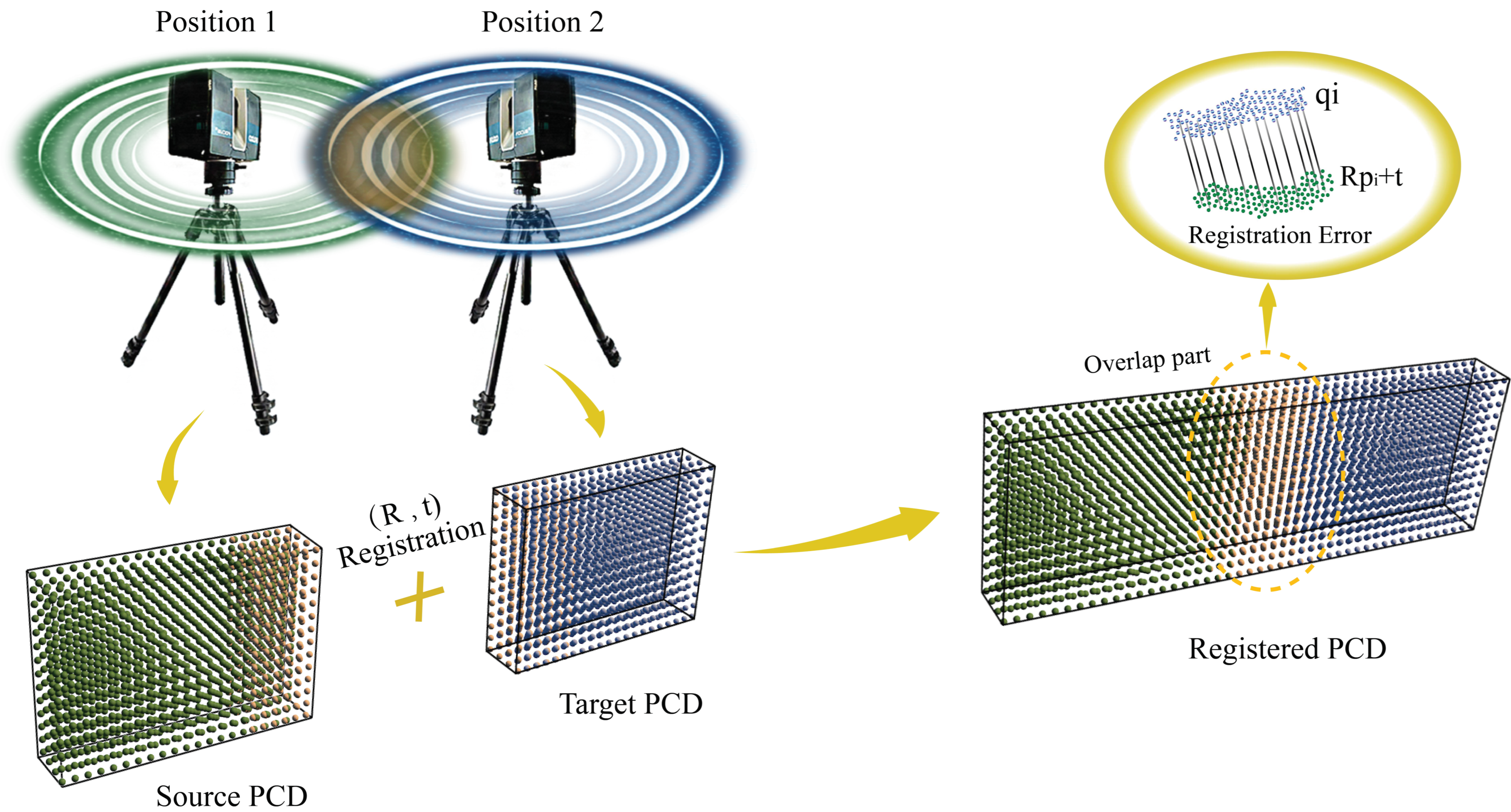
Once Step 1 was complete, the two critical parameters—rotation matrix R and translation vector t—had become known quantities. To calculate the RE between each source and target point cloud, we first aligned the source and target point clouds using the known rotation matrix R and translation vector t. Next, we obtained the number of point pairs by searching for corresponding points once more (see Figure 2). We then calculated the vector difference between each pair of points, and finally, computed the average of these differences. The final formula can be expressed as
RE   = 1 N i N R p i + t q i
where N is the number of point pairs; p i and q i are the corresponding points in the source and target point clouds, respectively; R is the rotation matrix; and t is the translation matrix.
To compute the SOR, we used the Jaccard index method. In addition to the number of point pairs (No), the number of points in the source and target point clouds must also be predetermined. In the SOR calculation, point pairs are those located in the intersecting portion of the source and target point clouds. The total number of points in the source and target point clouds minus the number of points in the overlapping part was considered the union part. From this, we can derive the following calculation:
S O R = S T S T = N o N s + N t N o
where S represents the source point cloud, T represents the target point cloud, No represents the number of point pairs, Ns represents the total number of points in the source PCD and Nt represents the total number of points in the target PCD.

3.3. Data Quality

The final finely registered PCD models for each scenario had different levels of data quality. To calculate the PE and CR for each scenario, three elements are essential: the complete finely registered PCD model for each scenario, the ground truth values and the ground truth model. The following sections present the full process used for the data processing of essential elements and for calculating PE and CR.

3.3.1. Step 1: Prepare and Process the Finely Registered PCD Model, Ground Truth Values and Ground Truth Model

The ground truth values served as the foundation for calculating PE. In multi-technology fusion, different technologies are used to collect point clouds from different parts of a building. In some areas, more than three techniques may be used, resulting in inconsistent PE values in different parts of the final finely registered model. Under such circumstances, the arrangement of ground truth values needs to be comprehensive. First, ground truth values should apply to a range of building regions. Second, ground truth values should encompass a diverse range of lengths. Third, for special areas involving the fusion of multiple technologies, a greater number of ground truth values needs to be obtained. The arrangement of ground truth values used in the experiments is presented in Section 4.1.
The finely registered PCD model was generated by registering all scans within a single scenario and was the basis for calculating PE and CR. Once registration was complete, we measured the corresponding values—referred to as measured values—at the same positions as the ground truth values within the point cloud. Once all measured values were recorded, we performed downsampling on the finely registered model. This process resulted in 10 downsampled finely registered PCD models at different resolutions (0.01–0.1 m) at 0.01 m intervals, which were then used for calculating the CR.
The preferred ground truth models, which represent real-world conditions, are high-precision as-built BIM models. In this paper, the method for calculating the CR required the advance voxelisation of the as-built model. The entire process involved three steps:
  • We converted the as-built BIM model into a mesh model.
  • We performed uniform dense sampling on the mesh surface to generate a dense point cloud.
  • We converted the dense point cloud into voxels to create a voxel model. A total of 10 voxel models were generated, with voxel size ranging from 0.05 m to 0.5 m at 0.05 m intervals.
Before performing point cloud downsampling and converting the mesh model into a voxel model, it is essential to ensure that the original finely registered PCD and mesh models have been properly registered (i.e., spatially aligned with consistent scales, using the same unit of length as the basis for measurement) and that the voxel grid coordinates maintain the same direction as the XYZ-axes of the world coordinate system in which the mesh model resides.
After data processing, we obtained the ground truth and measured values. For each scenario, 10 finely registered PCD models with different resolutions and 10 voxel models with varying voxel sizes were generated (see Figure 3).

3.3.2. Step 2: Calculation of PE and CR

Based on the ground truth and measured values obtained in Step 1, we calculated PE as follows:
P E = X t X m
where Xt represents the ground truth value and Xm represents the measured value.
We propose a method—the voxel centroid approach—to calculate the CR value. In Step 1, we obtained finely registered PCD models at different resolutions for each scenario and voxel models with different voxel sizes. The CR was calculated according to the following five steps:
  • Input each downsampled PCD model and each voxel model.
  • Construct a k-dimensional (k-d) tree for the point cloud to optimise the data structure and enable efficient nearest-neighbour searching.
  • Calculate the centre of each voxel in the voxel model as
    C = V o + I   d + d 2
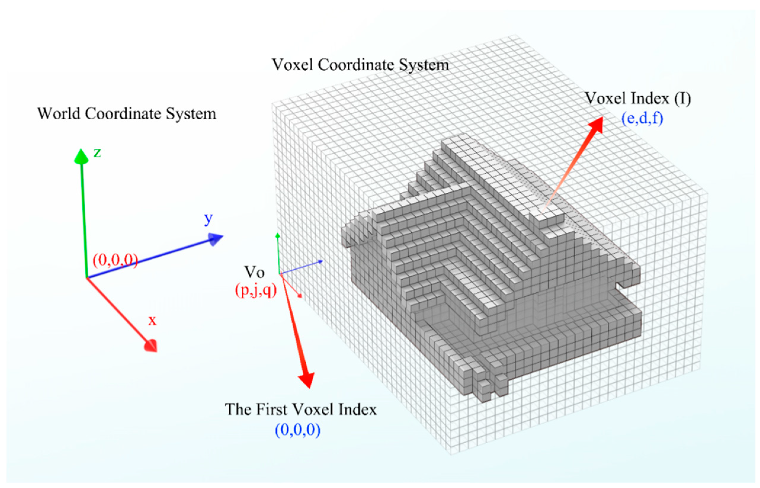
    where C represents the coordinate of the centre of the current voxel in the world coordinate system, Vo denotes the coordinates of the voxel coordinate system’s origin in the world coordinate system, I represents the index of the current voxel, and d denotes the voxel size (see Figure 4).
  • Utilise the k-d tree to search for the point nearest to each voxel centre, and determine whether the voxel is occupied. For each voxel centre (C), find the nearest point (P) using the k-d tree. Calculate the distance between C and P. If the distance is less than half of the voxel’s edge length (i.e., <d/2, where d is voxel size), define the voxel as occupied (see Figure 5).
  • Calculate the CR of the corresponding point cloud as follows:
    C R = N p N
    where Np represents the number of occupied voxels and N represents the total number of voxels.

3.4. Regression Analysis

In our study, we employed regression analysis to estimate the coefficients. Among the three scenarios (Scenario 1, Scenario 2 and Scenario 3), Scenario 2 was designated as the control group. To see how much the dependent variable (RE, SOR, PE and CR) changed when we moved from Scenario 2 to either Scenario 1 or Scenario 3, we used separate dummy variables in our regression models. The dummy variables were assigned values of 0 or 1. For an observation in Scenario 1, the dummy variable for Scenario 1 was 1, and for Scenario 3, it was 0. If an observation was in Scenario 3, the dummy variable for Scenario 3 was 1, and for Scenario 1, it was 0. This assignment strategy signifies the presence or absence of the respective scenarios in the observation. The computed correlation coefficients for Scenarios 1 and 3 represent the magnitude and direction of the changes in these scenarios relative to Scenario 2. Specifically, a negative coefficient implied a decrease, while a positive coefficient suggested an increase. The regression model was established as follows:
R E = β 0 + β 1 ×   Scenario   1   + β 3 ×   Scenario   3   + + ε
S O R = β 0 + β 1 ×   Scenario   1   + β 3 ×   Scenario   3   + ε
P E = β 0 + β 1 ×   Scenario   1   + β 3 ×   Scenario   3   + ε
C R = β 0 + β 1 ×   Scenario   1   + β 3 ×   Scenario   3   + ε
where the Scenario 1 and Scenario 3 terms correspond to the dummy variables for these scenarios; β0 is the intercept term of the regression equation, while β1 and β3 represent the regression coefficients associated with Scenarios 1 and 3, respectively; lastly, ε stands for the error term, capturing the variance not explained by the model.

4. Experimental Setup

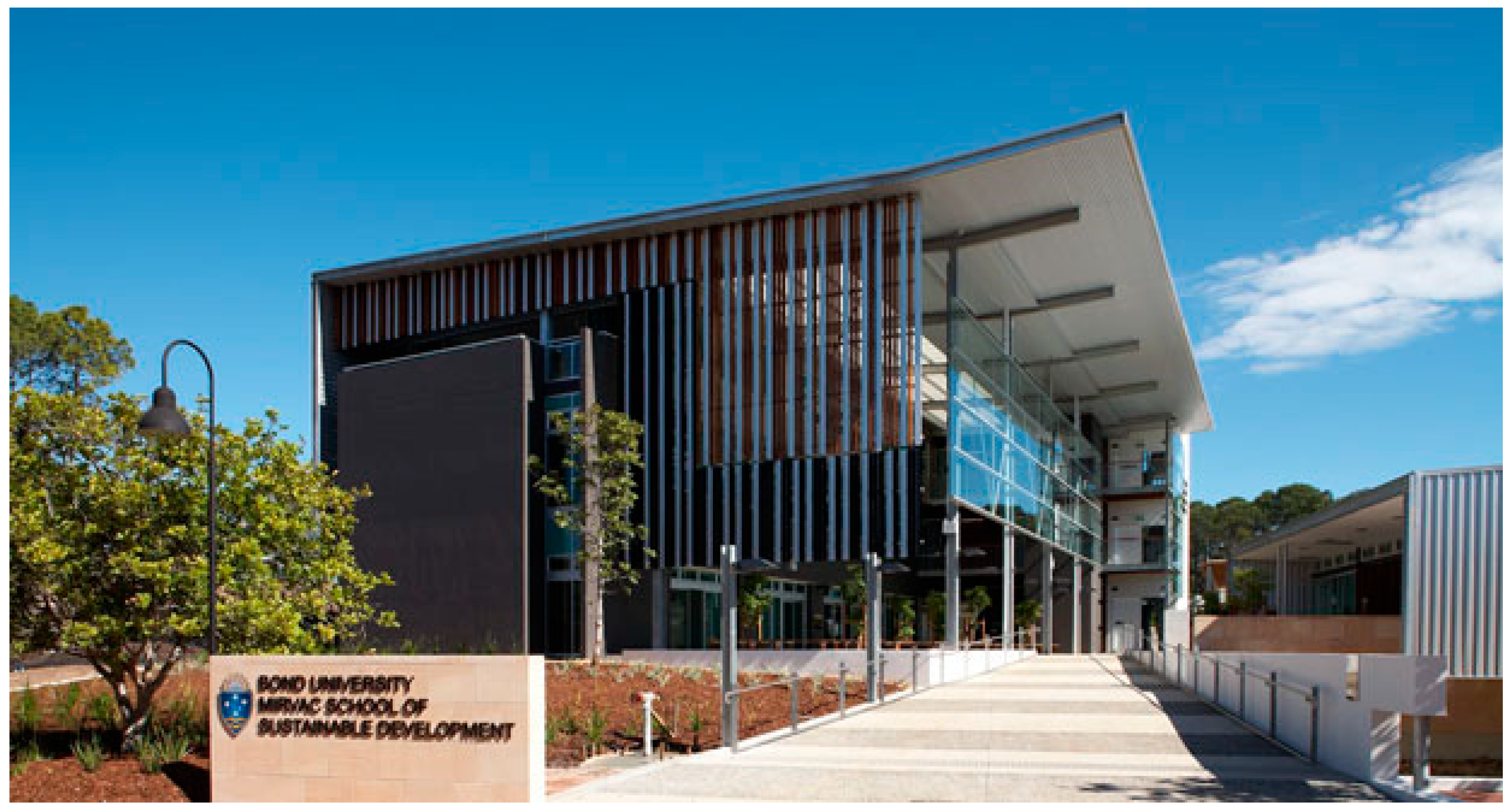
Bond University’s Sustainable Building (see Figure 6) is a remarkable structure, boasting state-of-the-art eco-friendly features and a cutting-edge design. Located in Gold Coast, Australia, this iconic building has set the standard in green building practices, featuring an energy-efficient design, rainwater collection, natural ventilation systems, and optimal use of daylight, earning it a 6-Star Green Star Rating—the highest sustainability rating in Australia. This building was selected as the scanning target for this experiment. The specific building components for point cloud data (PCD) collection included floors, ceilings, walls, columns, doors, windows, roofs and external decorations. All other components captured in the PCD, such as tables, chairs and trees, were considered noise points and removed following the registration process.
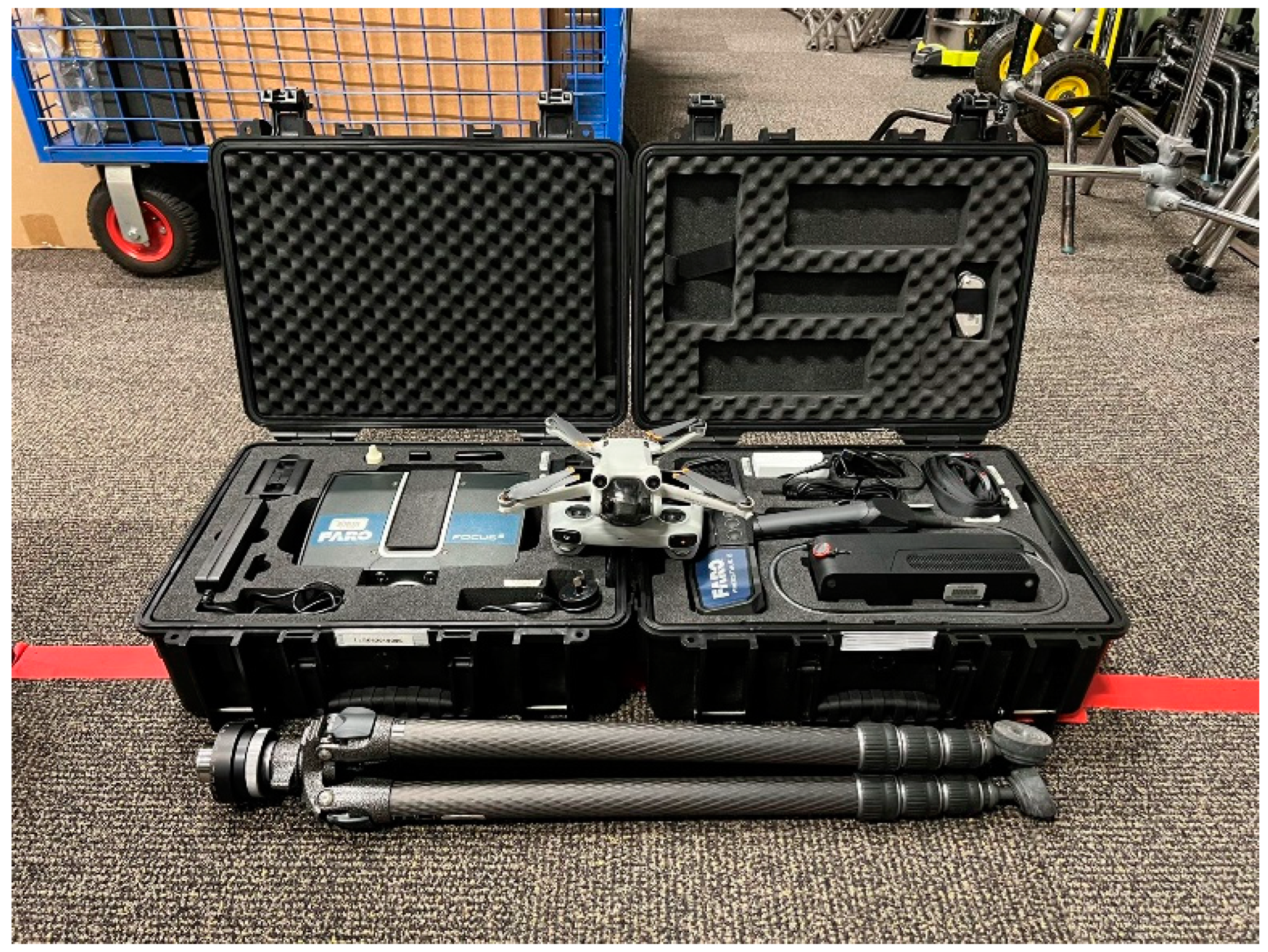
In this experiment, we developed three different PCD collection scenarios based on either scan planning or no scan planning and either a single technology (TLS) or multi-technology fusion. The first PCD collection method (Scenario 1) was based on TLS without advance scan planning to collect point clouds for the entire building. The second method (Scenario 2) was based on TLS with scan planning to scan the entire building. The third method (Scenario 3) simultaneously used TLS, MLS and UAVDP to scan buildings after performing advance scan planning (see Table 1). In this research, we used FARO Focus S70 (FS70) to represent TLS, FARO Freestyle 2 (FF2) to represent MLS and DJI Mini 3 Pro plus Bentley Systems ContextCapture software to represent UAVDP (see Figure 7).

4.1. Preparation: Ground Truth Values and Model

Ground truth values were collected using a laser rangefinder with accuracy of within 1 mm and were considered the baseline for the point cloud. First, we posted 100 markers (in two groups of 50) in various points throughout the building, including in each room, the corridors and the outdoor open spaces. Each group of markers was levelled to the same height using the laser level (Figure 8). Once the markers had been posted, we used a laser rangefinder to collect truth values for each target group. In total, 50 ground truth values were obtained, and the PCD generated in each scenario had 50 corresponding measured values.
A complete as-built BIM model was employed as the ground truth model to assist in the calculation of the CR values. The as-built BIM model (see Figure 9), provided by Bond University, was created based on highly accurate PCD and other surveying data. The research team ensured the integrity of the model by comparing it with real-world conditions. Additionally, the as-built BIM model was converted into 10 voxel models with sizes ranging from 0.05 m to 0.5 m at 0.05 m intervals.

4.2. PCD Collection

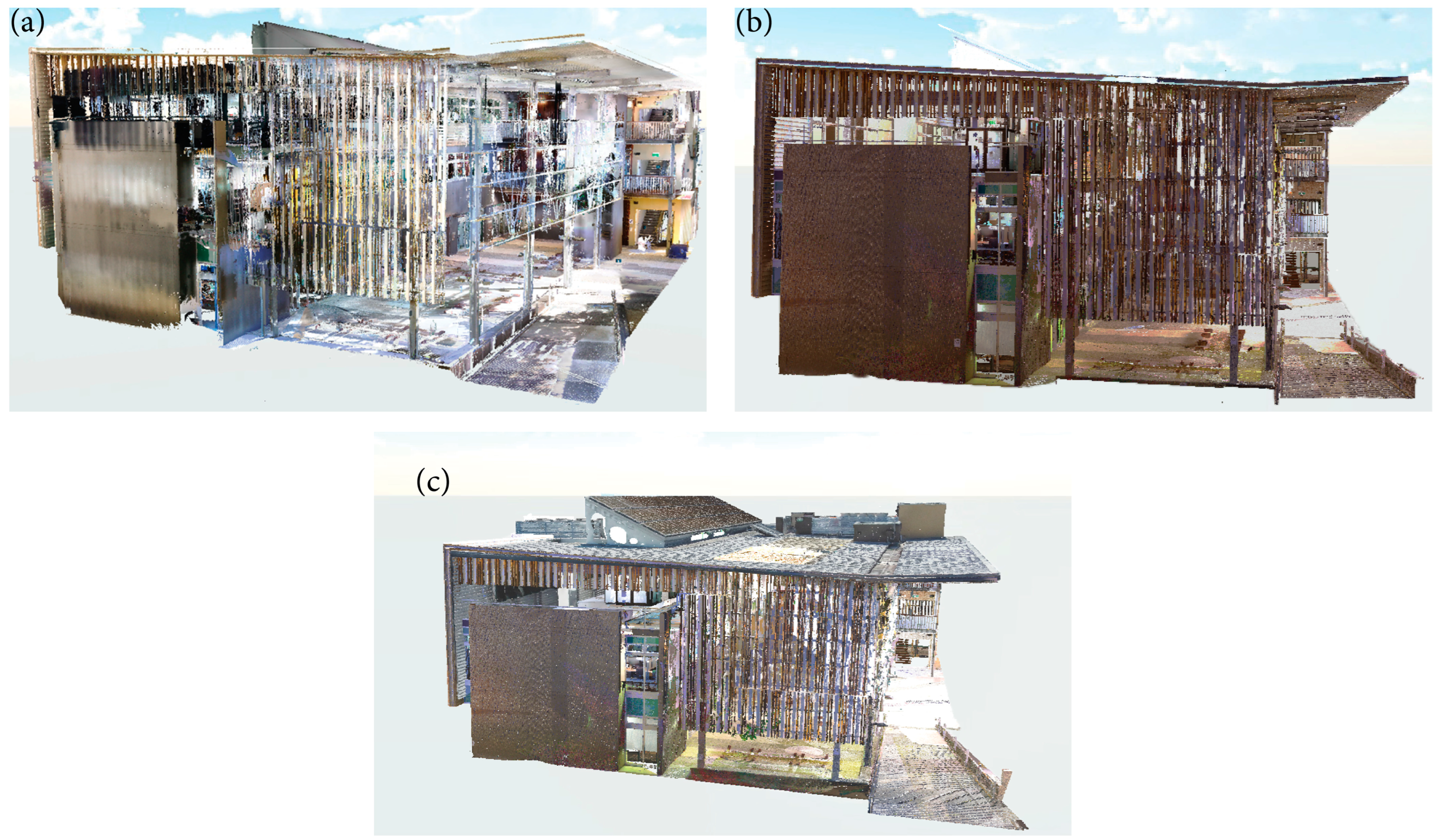
For each scenario, several scans were generated to capture the PCD for different building parts. Every two scans within the same scenario were registered as a scan pair. Ultimately, each scenario produced original finely registered PCD (see Figure 10). After establishing spatial alignment with the mesh model, we downsampled the PCD within the same spatial coordinate system, generating 10 downsampled PCD ranging from 0.01 m to 0.1 m at 0.01 m intervals.

4.2.1. Scenario 1: TLS Method

Scenario 1 involved the use of TLS without advance scan planning for the collection of PCD from the building. The primary device used for the TLS method was the FS70. In the experiment, the actual scanning was performed by a professional who had over 2 years of point cloud collection experience. He was instructed to set up the FS70 directly at the site without prior scan planning, solely relying on his understanding and experience of the site. The resolution and quality parameters of the FS70 were set at 1/4 and 3, respectively. The estimated time for a single scan was 6 min and 49 s. Given that the experiment mostly took place indoors, the GPS was not activated. However, the inclinometer and compass were activated to provide correction parameters during the post-registration process. PCD collection progressed from indoor to outdoor environments and from lower to higher elevations. A total of 90 scans was collected using TLS, and 88 scan pairs were produced by registering adjacent scans in pairs.

4.2.2. Scenario 2: Scan Planning Plus TLS Method

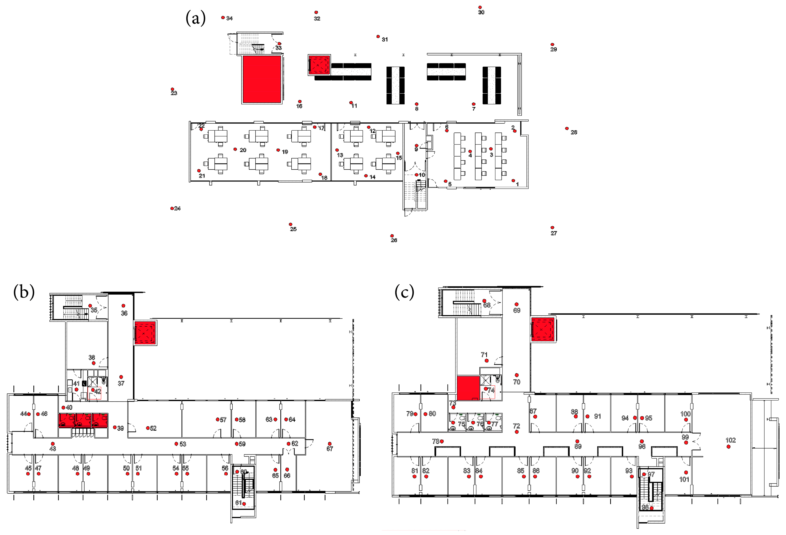
Scenario 2 involved the use of advance scan planning to determine reasonable scan positions for the TLS scanner. The FS70 was still the primary device utilised for PCD collection in this scenario. In the experiment, the actual executor remained the same as in Scenario 1. However, in Scenario 2, they were allowed to perform scan planning in advance using design drawings and then place the FS70 according to the scan plans (see Figure 11). In designing the scan plan, the TLS scanner positions were mainly determined using the following two rules: first, the potential impact of obstructions had to be considered; second, the numbering of the scan positions had to be coherent to avoid any issues during the three-point registration. All scan parameters of the FS70 were consistent with those utilised in Scenario 1. A total of 102 scans were collected using TLS, and 97 scan pairs were produced by registering adjacent scans in pairs.

4.2.3. Scenario 3: Scan Planning Plus TLS Plus MLS Plus UAVDP Method

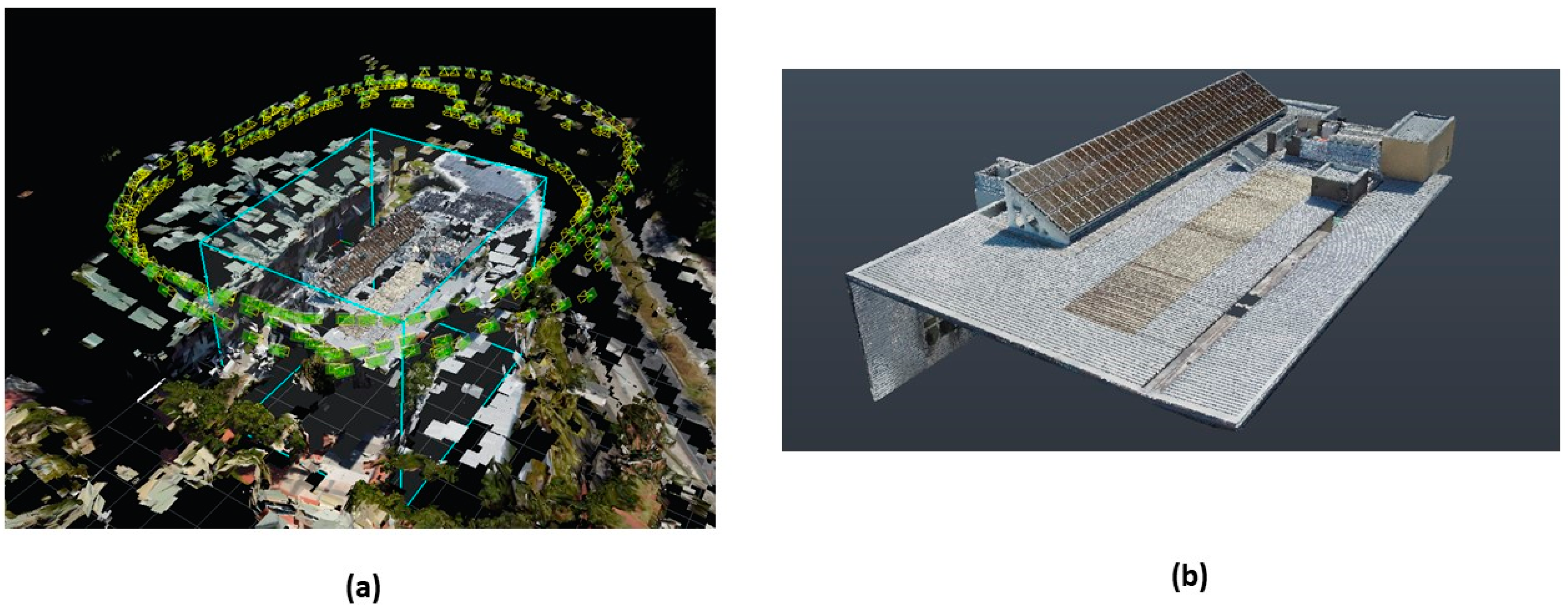
Scenario 3 built on Scenario 2 and incorporated MLS and UAVDP in addition to TLS and scan planning. The devices utilised in this scenario were the FS70, the FF2 and DJI Mini 3 Pro plus ContextCapture software. As in Scenario 2, the actual executor remained the same, and design drawings served as the basis for scan planning in Scenario 3 (see Figure 12). However, the entire building area was divided into three distinct zones: the first comprised open spaces and corridors, which are generally larger and have fewer obstructions than rooms; the second comprised rooms, which are smaller and contain numerous obstructions compared with open spaces and corridors; and the third comprised the roof area, which is considered a high-risk zone given the challenges in collecting PCD using the FS70 and the FF2. The installation locations of the FS70 and the flight trajectory and altitude of the UAV were preplanned. The FS70 parameters were the same as those used in Scenarios 1 and 2. With respect to the FF2 parameter settings, the data range was set to 3 m, and plan detection was disabled. Scan optimisation and stray point filtering were both set to standard. In addition, the 20 small markers included in the FF2 kit were used to assist each FF2 room scan. The flight path and altitude of the DJI Mini 3 Pro involved circumnavigating the target building, with the camera facing downwards at an angle of 30 degrees from a height of 15 m and at 45 degrees from a height of 20 m (see Figure 13). We collected a total of 40 scans with TLS, 53 scans with MLS and 1 scan created from 102 images obtained with UAVDP, and 93 scan pairs were produced by registering adjacent scans in pairs.

5. Results

5.1. RE

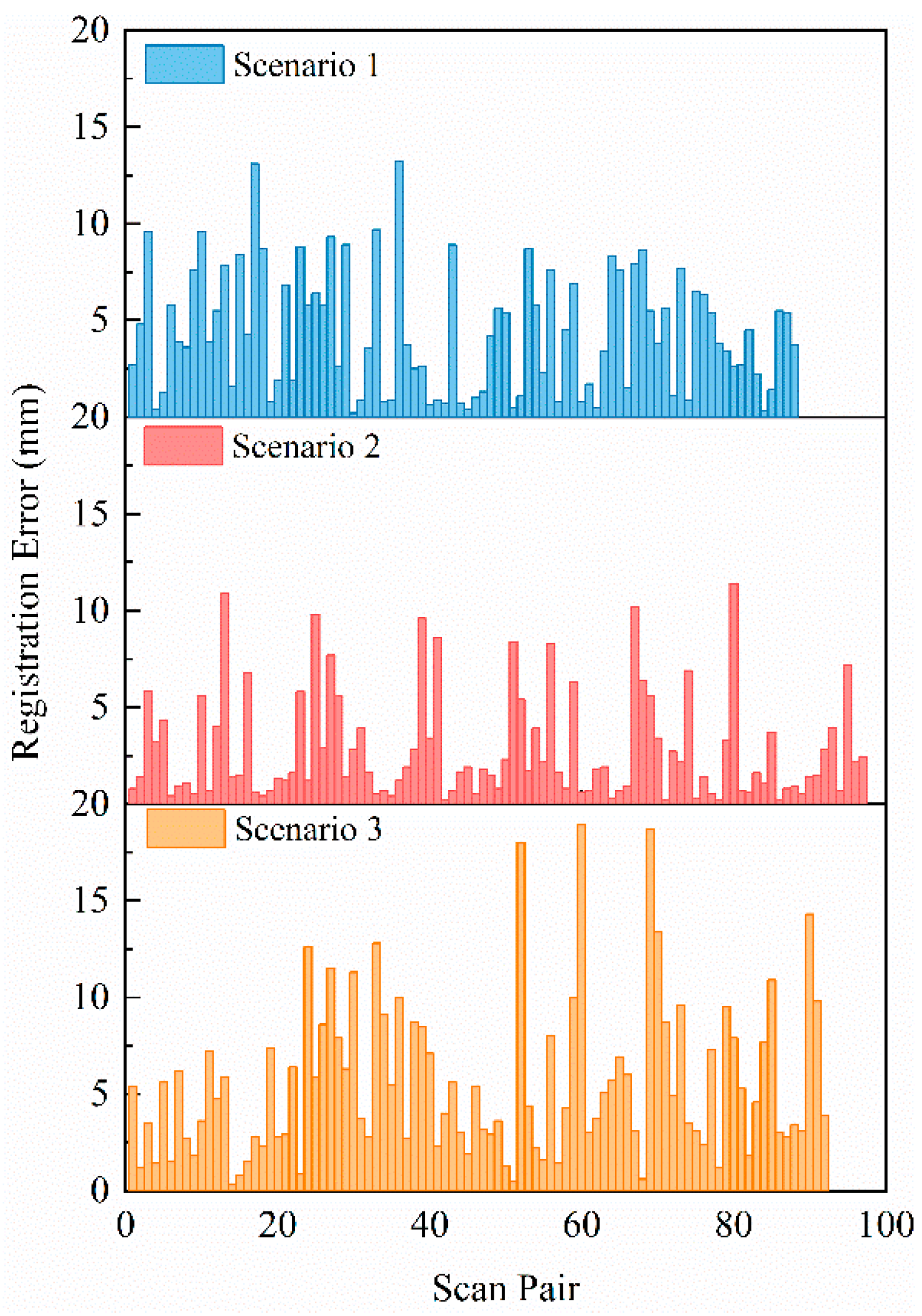
Based on the scan pairs, 88 RE values were calculated for Scenario 1; 97, for Scenario 2; and 93, for Scenario 3 (see Figure 14). Table 2 shows that the ranges of RE values were 0.2–13.2 mm in Scenario 1, 0.2–11.4 mm in Scenario 2 and 0.3–18.9 mm in Scenario 3. The differences between the maximum and minimum RE values were 13 mm for Scenario 1, 11.2 mm for Scenario 2 and 18.6 mm for Scenario 3. Standard deviations were 3.19 mm for Scenario 1, 2.79 mm for Scenario 2 and 4.11 mm for Scenario 3. Therefore, among the three scenarios, Scenario 3 exhibited the largest range and the highest degree of variability in RE values, with the most dispersed data distribution. Conversely, Scenario 2 demonstrated the smallest range and the lowest degree of variability, with the most concentrated data distribution. If we set the acceptable RE value to within 1 cm, 12% of RE values in Scenario 3 exceeded this threshold (compared with only 2% in Scenario 1 and 3% in Scenario 2). These results indicate that the method used in Scenario 3 for PCD collection, using the same point cloud registration method, resulted in the lowest point cloud registration accuracy among the three scanning methods employed. A possible reason for this may be that Scenario 3 was the only scenario that involved nonhomogeneous point cloud registration, while Scenarios 1 and 2 only involved the registration of data collected using the FS70.
According to the regression analysis results (see Table 3), the method used in Scenario 1 significantly increased RE values by an average of 1.60 mm compared with Scenario 2 at a significance level of 1% (p = 0.002). Scenario 3 significantly increased the RE values by an average of 2.84 mm compared with Scenario 2, also at a 1% significance level (p = 0.000). From this, we can draw two conclusions. First, when using TLS, scan planning significantly reduces the RE values, improving the registration accuracy of the point cloud. Second, when scan planning is applied in both cases, the multi-technology fusion method is significantly less accurate with respect to registration than the TLS method alone.

5.2. SOR

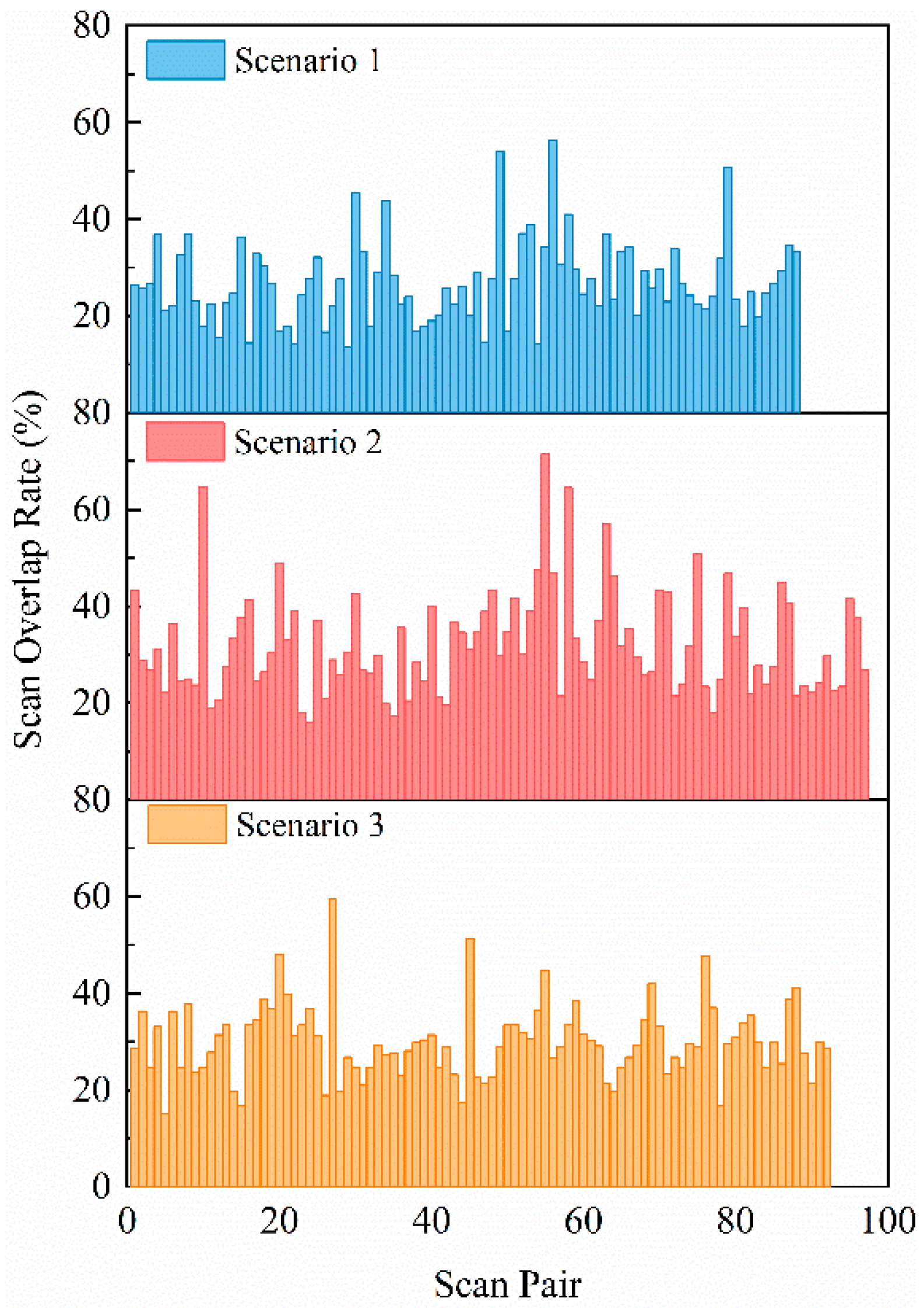
Based on the scan pairs, 88 SOR values were calculated for Scenario 1; 97, for Scenario 2; and 93, for Scenario 3 (see Figure 15). Table 4 shows that the ranges between the maximum and minimum SOR values were 42.8%, 55.5% and 44.6% for Scenarios 1, 2 and 3, respectively. Standard deviations were 3.19 mm for Scenario 1, 2.79 mm for Scenario 2 and 4.11 mm for Scenario 3. Scenario 2 had 12 more scans than Scenario 1 and 8 more scans than Scenario 3; however, the degree of variability and data distribution of the SOR values in Scenario 2 was the highest and largest among all scenarios. This indicates that an increased number or density of scan positions does not necessarily guarantee a more concentrated SOR value. If we set the acceptable standard for SOR values to more than 20%, 20% of SOR values in Scenario 1, 7% in Scenario 2, and 9% in Scenario 3 failed to meet this standard. Moreover, Scenario 1 also had the lowest mean SOR value, 26.92%, which is greater than the acceptable standard of 20%. Scenario 2 had the highest mean SOR value, 32.17%, and Scenario 3 stood at 30.07%. Considering the results of RE values, the increase in SOR values indeed had a positive impact on registration accuracy, reducing the RE values, such as in Scenario 1 vs. Scenario 2. However, in Scenario 3, due to the factors of nonhomogeneous point cloud registration, the increase in SOR values compared with Scenario 1 did not lead to an improvement in registration accuracy.
The regression analysis results (see Table 5) show that the SOR values in Scenario 1 were significantly reduced by 5.24% compared with Scenario 2 at a 1% significance level (p = 0.000). Although the average SOR values of Scenario 3 were reduced by 2.1% compared with that of Scenario 2, there was no significant relationship (p = 0.116). From this, we can infer that scan planning significantly improves the SOR values between scans for PCD collection. Compared with the exclusive use of TLS or homogeneous point clouds, multi-technology fusion or nonhomogeneous point clouds do not significantly reduce the SOR values between the source and target PCD during point cloud registration using the same point cloud registration method.

5.3. PE

Ground truth values based on 50 data points ranged from 1.240 m to 21.670 m. These ground truth values were paired with the measured values obtained from the finely registered PCD, resulting in PE values (see Table 6). As shown in Figure 16, as the ground truth values increased, the PE values calculated from the corresponding measured values for each scenario also increased. Of the three scenarios, Scenario 3 showed the most noticeable increase. In contrast, the proportion of PE values to the corresponding ground truth values was reduced. If a ground truth value was larger, the PE proportion was lower, indicating that the rate of error growth is much slower than the rate of ground truth value increase. Considering the overall data, if we adopted a criterion of less than 1 cm for acceptable PE values, 14% of the PE values in Scenario 3 did not meet this standard, whereas both Scenario 1 and Scenario 2 exhibited 0% of PE values that fail to meet this criterion. When ground truth values were less than 10 m, PCD measurements typically involved one-to-three scans, generating 29 PE values for each scenario. Of these cases, 100% of the PE values for each scenario were controlled within 1 cm. Under these conditions, the mean PE values for Scenarios 1, 2 and 3 were 1.17 mm, 0.59 mm and 3.52 mm, respectively. Conversely, when the ground truth value exceeded 10 m, PCD measurements typically involved more than three scans, resulting in 21 PE values for each scenario. In Scenarios 1 and 2, 100% of the PE values were less than 1 cm, while in Scenario 3, only 67.67% of the PEs were controlled within 1 cm. Under these conditions, the mean PE values for Scenarios 1, 2 and 3 were 3.24 mm, 2.29 mm and 8.52 mm, respectively. Consequently, larger PCD measurements typically require more scans and may have a compounding effect on errors, with the use of multi-technology fusion exhibiting larger PE values accumulation than the use of TLS alone.
The regression analysis results (see Table 7) show that Scenario 1 had an average increase of 0.74 mm in PE values compared with Scenario 2, but this difference was not statistically significant (p = 0.136). In contrast, Scenario 3 had an average increase of 4.32 mm in PE values compared with Scenario 2 at a 1% significance level (p = 0.000). These data suggest that when using only TLS for PCD collection, scan planning does not significantly reduce PE values, meaning that it does not significantly improve measurement accuracy. With scan planning, the use of multi-technology fusion results in a significant increase in PE values compared with TLS alone, indicating a decrease in accuracy.

5.4. CR

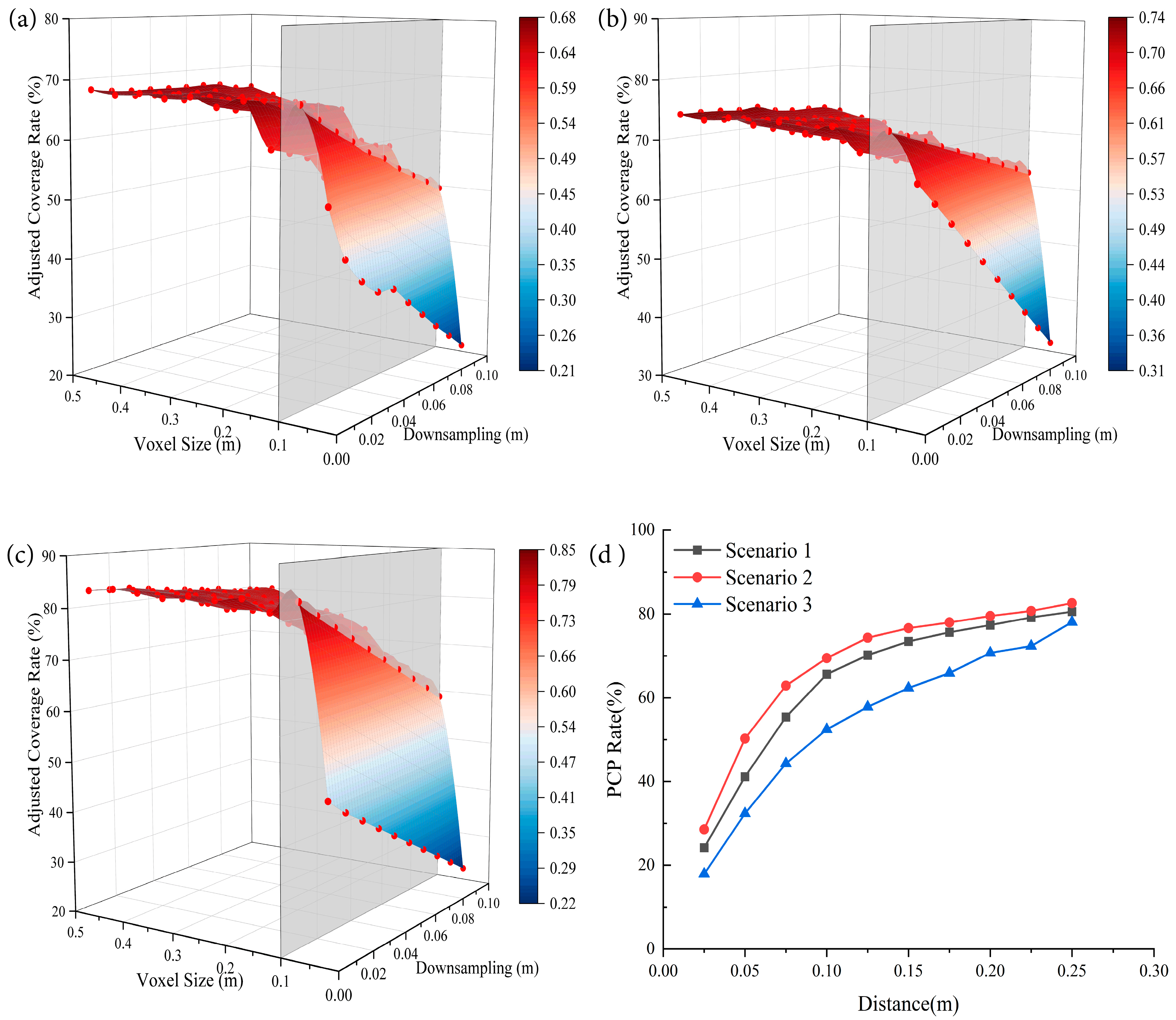
In this study, we introduced a voxel centroid approach to calculate CR values from 10 downsampled PCD and 10 voxel models with varying voxel sizes for each scenario, resulting in 100 CR values per scenario (a total of 300 CR values) (see Table 8). As illustrated in Figure 17, the CR values were significantly influenced by the voxel size parameter. Given the considerable variation in results within the same scenario, we believe that the outcome does not adequately reflect point cloud completeness. To determine the cause of these results, we further calculated the discrepancies between the ground truth model and the original point cloud (i.e., the undownsampled PCD model) using CloudCompare software (see Figure 18). The average distances between the ground truth models and the PCD models in Scenarios 1, 2 and 3 were 0.14 m, 0.13 m and 0.21 m, respectively. Additionally, we performed a filtering operation based on the distance from the original point cloud to the ground truth model. We found that as the distance threshold decreased, the proportion of points in the PCD that meets the distance requirement became smaller in relation to the overall point cloud (see Figure 18). This indicates that even if a particular portion of the point cloud is complete, the CR value for that portion may still be considerably low. Given the persistent distance discrepancy between the point cloud and the ground truth model following alignment, as the voxel size decreases, fewer points in the PCD can participate in CR calculation, ultimately leading to significantly underestimated results.
To address this issue, we propose the point cloud participation (PCP) rate as a compensatory value to reduce the effect of the distance between the ground truth model and the original point cloud of each scenario. The PCP rate represents the proportion of points in the original point cloud that are within a certain threshold distance (typically half the voxel size; that is, d/2) from the ground truth model. The calculation is as follows:
R_p = M/T
where R_p denotes the PCP rate, M is the number of points in the original point cloud with a distance from the ground truth model less than or equal to the threshold (d/2) and T is the total number of points in the original point cloud.
To incorporate the PCP rate (R_p) into the CR calculation, we define an adjusted CR (CR_adj) as
CR_adj = CR/R_p
where the CR values obtained under the same scenario and voxel size are compensated with the corresponding PCP rate calculated under the same scenario and voxel size, using half the voxel size as the threshold distance.
For each scenario, 10 PCP rates were calculated based on the distance from the original point cloud to the ground truth model (d/2), resulting in a total of 30 PCP rates. Consequently, 100 adjusted CR values were derived for each scenario, yielding a total of 300 CR_adj values (see Table 9). As shown in Figure 19d, the PCP rate continuously increased with the distance threshold, showing that a significant proportion of points was not close to the ground truth model surface. As the voxel size increases, more points can participate in the calculation of the CR value, thereby reducing the effect of the distance between the point cloud and ground truth model. With respect to the adjusted CR value trend, it is evident that a voxel size of 0.1 served as a demarcation point (see Figure 19). When excluding data with a voxel size of 0.05, the fluctuation range between the minimum and maximum values for Scenarios 1 to 3 could be controlled within 18.77%, 11.53% and 24.26%, respectively. Standard deviations for unadjusted CR values decreased from 14.32% to 5.29% for Scenario 1, from 13.57% to 3.40% for Scenario 2, and from 17.16% to 5.73% for Scenario 3. These results clearly demonstrate that CR values adjusted using PCP rate exhibit a higher degree of stability in reflecting the data completeness of point clouds than unadjusted CR values, significantly reducing the influence of the voxel size parameter.
According to the regression analysis (see Table 10), the CR_adj was significantly reduced by an average of 7.52% in Scenario 1 compared with Scenario 2 at a 1% significance level (p = 0.000). Further, CR_adj significantly increased by an average of 5.29% in Scenario 3 at a 1% significance level (p = 0.001). From this, we conclude that the application of scan planning in cloud collection methods significantly improves data completeness compared with no scan planning. Moreover, point cloud collection methods using multi-technology fusion significantly improve data completeness compared with the exclusive use of TLS.

6. Discussion

6.1. Findings

The key findings from our study are as follows:
  • Nonhomogeneous point cloud registration (as observed in Scenario 3) exhibited the largest range and the highest degree of variability in RE values, with the most dispersed data distribution, compared with homogeneous registration (as observed in Scenarios 1 and 2). The difference between the maximum and minimum RE values was 18.6 mm for Scenario 3, which was greater than that for Scenario 1 by 5.6 mm and exceeded that for Scenario 2 by 7.4 mm, respectively. The standard deviation of RE values was 4.11 mm for Scenario 3, which was greater than that for Scenario 1 by 0.92 mm and that for Scenario 2 by 1.32 mm.
  • The application of scan planning in Scenario 2 significantly reduced the RE values by an average of 1.6 mm compared with the no scan planning approach in Scenario 1, demonstrating an improvement in point cloud registration accuracy. Furthermore, the multi-technology fusion method in Scenario 3 generated significantly lower registration accuracy, with an average decrease of 2.84 mm in RE values compared with the TLS method in Scenario 2. Moreover, there were 12% of RE values in Scenario 3 that exceeded 1 cm (compared with only 2% in Scenario 1 and 3% in Scenario 2).
  • Compared with no scan planning (Scenario 1), the use of advance scan planning (Scenario 2) for PCD collection could significantly improve the registration coincidence rate between scans, with an average increase of 5.24% in SOR values. Additionally, employing multiple technologies (Scenario 3) or nonhomogeneous point clouds using the same point cloud registration method did not significantly affect the registration coincidence rate between source and target PCD during point cloud registration compared with using solely TLS (Scenario 2).
  • An increase in SOR values had a positive effect on registration accuracy, as evidenced by Scenario 2, which had an average SOR value 5.25% higher than that of Scenario 1 while exhibiting an average reduction of 1.6 mm in RE values. However, under the influence of nonhomogeneous point clouds, an increase in SOR values did not necessarily lead to an improvement in registration accuracy. For instance, although the average SOR values in Scenario 3 were 3.15% higher than those in Scenario 1, the average RE values were 1.24 mm higher than those in Scenario 1.
  • Compared with the use of a single technology (TLS), a fusion of multiple technologies led to a wider and less stable PE distribution range in PCD.
  • Scan planning did not significantly reduce PE values in PCD collection, indicating no significant improvement in data accuracy. However, the use of multi-technology fusion (Scenario 3) significantly increased PE values by an average of 4.32 mm compared with the use of TLS alone (Scenario 2), suggesting a decrease in data accuracy. Moreover, 14% of PE values in Scenario 3 exceeded 1 cm, whereas both Scenario 1 and Scenario 2 exhibited 0% of PE values exceeding this threshold.
  • As the measured values increased, the use of multi-technology fusion for PCD collection tended to generate more severe error accumulation than TLS-based techniques. When ground truth values were less than 10 m, the mean PE values for Scenarios 1, 2 and 3 were 1.17 mm, 0.59 mm and 3.52 mm, respectively. Conversely, when the ground truth value exceeded 10 m, the mean PE values for Scenarios 1, 2 and 3 were 3.24 mm, 2.29 mm and 8.52 mm, respectively.
  • The calculation of CR values was significantly influenced by voxel size because of discrepancies between ground truth model and PCD, leading to considerable variations in results within the same scenario. Indeed, the PCP rate, when utilised as a compensatory value, effectively mitigated the influence of voxel size on the results to a certain extent. This, in turn, led to more stable and reliable data outcomes.
  • The implementation of scan planning and multiple technologies played a positive role in the improvement of data completeness. The application of scan planning (Scenario 2) in cloud collection methods significantly increased the CR_adj values by an average of 7.52% compared with no scan planning (Scenario 1). Moreover, point cloud collection methods using multi-technology fusion (Scenario 3) significantly increased the CR_adj values by an average of 5.29% compared with the exclusive use of TLS (Scenario 2).

6.2. Recommendations

Based on the findings of this study, we make the following recommendations:
  • In situations where only TLS is available, scan planning may be essential for specific applications, such as quality inspection based on point clouds. This conclusion is based on our experimental results, which show an average coverage improvement of 7.52% when scan planning was employed (Scenario 1) compared with scenarios without scan planning (Scenario 2). This improvement was statistically significant. In many point cloud applications, such as quality inspections, achieving sufficient coverage is crucial. Insufficient coverage in point cloud data may hinder the detection of defects, such as cracks on wall surfaces or dimensional inaccuracies. However, the utilization of scan planning methods is not without drawbacks. To elaborate, in Scenario 2, there were 12 more scan positions than in Scenario 1, leading to an additional scan time of 81 min and 48 s. Yet, there was no a significant difference in data accuracy between point cloud data collected with and without scan planning. In relatively simple application scenarios, such as the scan-to-BIM reconstruction of a basic room, the implementation of scan planning might be time-consuming without providing substantial improvements in data accuracy. While it may enhance data completeness, the significance of this factor decreases for straightforward and uncomplicated structures. However, for applications in which high data completeness and data accuracy are required, such as quality assessment involving the observation of many components, employing scan planning to improve point cloud coverage rate would be prudent.
  • Our results show that the acquisition of PCD using multi-technology fusion may be a double-edged sword. In terms of registration and data accuracy, the use of multiple technologies generates larger average RE and PE values than the use of TLS alone. However, multi-technology fusion excels in point cloud CR_adj values, with Scenario 3 achieving average increases of 12.80% and 5.29% compared with Scenarios 1 and 2, respectively. Therefore, the use of multiple technologies for point cloud collection is highly suitable for scenarios that demand high data completeness but have less stringent data accuracy requirements, such as generating game environments, construction process tracking or creating digital models for management purposes. However, for point cloud applications that require higher accuracy, such as the detection of concrete cracking, the use of multiple technologies may not be suitable because of its uncontrollable error distribution and lower precision.
  • We found that the use of multi-technology fusion to collect PCD resulted in a wider and more unstable error distribution. Therefore, in future research requiring the quantification of point cloud accuracy, ground truth values should be arranged in different regions and across various distances throughout the building to ensure comprehensive coverage and more reliable results.

6.3. Limitations and Future Research Directions

The primary objective of this study was to investigate the effects of scan planning and multi-technology fusion on point cloud registration and data quality. However, this research had several limitations, which warrant consideration in future studies.
First, when examining the effect of scan planning on point cloud registration and data quality, we only considered the influence of positional factors, not the effects of different scanning parameters. A potential direction for future research may be to use different scanning parameters as variables, setting up corresponding scenarios and employing quantitative methods for registration and data quality to investigate their effects.
Second, we only compared the effects of TLS and multi-technology fusion on point cloud registration and data quality. However, many PCD collection technologies exist, and comparing these technologies in various combinations may yield different results. Thus, a potential future research direction may be to investigate registration and data quality outcomes using various other technology combinations.
Third, we employed the same registration method to investigate the effects of different PCD collection methods on data and registration quality. Different registration methods could potentially yield different results. Therefore, it may be appropriate to explore the influence of PCD collection methods using various registration methods, which could provide more comprehensive insights.
Fourth, this study presents a comprehensive approach to quantifying registration and data quality, specifically by employing an innovative method of calculating point cloud CR values using a voxel centroid approach. However, this method is limited, because despite the alignment between the ground truth model with the point cloud, a discrepancy between them still exists. This discrepancy results in only a portion of the point cloud being involved in CR value calculation. Currently, as-built BIM models are unable to avoid this discrepancy. First, when constructing as-built BIM models, modellers cannot overcome the limitations imposed by BIM software rules. For example, in Revit software, the angle between walls is a perfect 90-degree angle, while in point cloud models or the real world, the angle between walls may differ because of construction errors. Similarly, walls in Revit are perfect planes, while they have uneven surfaces in the real world. Second, although as-built BIM models are based on high-precision point clouds, manual modelling is still the mainstream approach, leading to the possibility of human errors in the modelling process. These factors make it difficult for as-built BIM models to align perfectly with the collected point cloud model.
When there is a discrepancy between the ground truth model and the point cloud, it is essential to ensure that at least half of the voxel size (d/2) is greater than the error between the point cloud and the model when calculating the CR. This ensures that a high proportion of the point cloud is involved in the calculation.
Given the challenges encountered by the current method, we recommend three future research directions to address these issues:
  • Investigate how to develop a ground truth model that perfectly fits with high-precision point clouds. One approach could involve moving away from traditional BIM authoring tools to develop an accurate method specifically tailored to point cloud modelling. Another approach could involve the use of high-coverage, high-precision point clouds themselves as the ground truth model; however, the challenge lies in collecting a high-coverage, high-precision point cloud while ensuring the integrity of the components within it.
  • Research the feasibility of projecting the point cloud onto the ground truth model surface before calculating the CR values. This could directly eliminate the distance between the point cloud and the ground truth model, potentially improving the accuracy of the CR calculation.
  • Similar to the current study, calculate the PCP rate as a compensating factor and subsequently calculate the adjusted CR value. However, while the current study calculated the PCP rate using the original PCD model and the ground truth model, future researchers could directly use the corresponding downsampled point cloud to calculate the PCP rate and compensate the CR value. This approach could yield more accurate results.
By pursuing these research directions, it may be possible to accurately compare the differences in point cloud quality among various PCD collection methods, investigate the effect of different variables on point cloud quality and develop more robust and accurate methods for quantifying point cloud registration and data quality.

7. Conclusions

This study aimed to investigate the effects of scan planning and multi-technology fusion on point cloud registration and data quality in various collection scenarios. We established three PCD collection scenarios and compared their registration and data quality to assess the effectiveness of scan planning and multi-technology fusion.
Registration quality was quantified using registration error (RE) and scan overlap rate (SOR), representing registration accuracy and registration coincidence rate, respectively. Data quality was quantified using point error (PE) and coverage rate (CR), representing data accuracy and data completeness, respectively.
Our findings indicate that scan planning significantly enhances registration accuracy and registration coincidence rate. However, it does not have a considerable impact on data accuracy. In contrast, the use of multi-technology fusion, when compared with the use of TLS-technology alone, results in reduced registration and data accuracy without significantly affecting the registration coincidence rate. Both scan planning and multi-technology fusion independently contribute to the positive impact on data completeness of point clouds.
This study offers valuable insights into the effects of scan planning and multi-technology fusion on point cloud registration and data quality. The quality data derived using the three PCD collection methods in the specific building context can serve as a reference for predicting point cloud quality in similar architectural environments using the same collection methods.

Author Contributions

Conceptualization, Z.Z.; methodology, Z.Z.; writing—original draft and software, Z.Z.; writing—original draft and investigation, T.C.; writing—review, editing and supervision, S.R.; writing—review, editing and validation, R.R.; data curation and visualization, X.R. All authors have read and agreed to the published version of the manuscript.

Funding

This research received no external funding.

Data Availability Statement

The data presented in this study are available upon request from the corresponding author.

Acknowledgments

The authors express sincere gratitude to Chris Grieve for the assistance provided in the preliminary preparation of this research and to Ben Hu for guidance in the data analysis method.

Conflicts of Interest

The authors declare no conflict of interest.

References

  1. Aydin, C.C. Designing building façades for the urban rebuilt environment with integration of digital close-range photogrammetry and geographical information systems. Autom. Constr. 2014, 43, 38–48. [Google Scholar] [CrossRef]
  2. Valero, E.; Bosché, F.; Forster, A. Automatic segmentation of 3D point clouds of rubble masonry walls, and its application to building surveying, repair and maintenance. Autom. Constr. 2018, 96, 29–39. [Google Scholar] [CrossRef]
  3. Ursini, A.; Grazzini, A.; Matrone, F.; Zerbinatti, M. From scan-to-BIM to a structural finite elements model of built heritage for dynamic simulation. Autom. Constr. 2022, 142, 104518. [Google Scholar] [CrossRef]
  4. Meyer, T.; Brunn, A.; Stilla, U. Change detection for indoor construction progress monitoring based on BIM, point clouds and uncertainties. Autom. Constr. 2022, 141, 104442. [Google Scholar] [CrossRef]
  5. Tang, P.; Huber, D.; Akinci, B.; Lipman, R.; Lytle, A. Automatic reconstruction of as-built building information models from laser-scanned point clouds: A review of related techniques. Autom. Constr. 2010, 19, 829–843. [Google Scholar] [CrossRef]
  6. Giel, B.; Issa, R. Using laser scanning to access the accuracy of as-built BIM. In Computing in Civil Engineering (2011); ASCE: Reston, VA, USA, 2011; pp. 665–672. [Google Scholar] [CrossRef]
  7. Liu, X.; Eybpoosh, M.; Akinci, B. Developing as-built building information model using construction process history captured by a laser scanner and a camera. In Proceedings of the Construction Research Congress 2012: Construction Challenges in a Flat World, West Lafayette, IN, USA, 21–23 May 2012; pp. 1232–1241. [Google Scholar] [CrossRef]
  8. Gao, T.; Akinci, B.; Ergan, S.; Garrett, J.H., Jr. Constructing as-is BIMs from progressive scan data. In ISARC, Proceedings of the International Symposium on Automation and Robotics in Construction, Eindhoven, The Netherlands, 26–29 June 2012; Citeseer: State College, PA, USA; Volume 29, p. 1. [CrossRef]
  9. Gao, T.; Akinci, B.; Ergan, S.; Garrett, J.H. A framework to generate accurate and complete as-built bims based on progressive laser scans. In Proceedings of the 30th International Symposium on Automation and Robotics in Construction and Mining, ISARC 2013, Held in Conjunction with the 23rd World Mining Congress, Montreal, QC, Canada, 11–15 August 2013. [Google Scholar] [CrossRef]
  10. Franchi, A.; Napoli, P.; Crespi, P.; Giordano, N.; Zucca, M. Unloading and reloading process for the earthquake damage repair of ancient Masonry columns: The case of the Basilica di Collemaggio. Int. J. Archit. Herit. 2022, 16, 1683–1698. [Google Scholar] [CrossRef]
  11. Wang, Q.; Kim, M.-K. Applications of 3D point cloud data in the construction industry: A fifteen-year review from 2004 to 2018. Adv. Eng. Inform. 2019, 39, 306–319. [Google Scholar] [CrossRef]
  12. Esfahani, M.E.; Rausch, C.; Sharif, M.M.; Chen, Q.; Haas, C.; Adey, B.T. Quantitative investigation on the accuracy and precision of Scan-to-BIM under different modelling scenarios. Autom. Constr. 2021, 126, 103686. [Google Scholar] [CrossRef]
  13. Zhu, Z.; Brilakis, I. Comparison of Optical Sensor-Based Spatial Data Collection Techniques for Civil Infrastructure Modeling. J. Comput. Civ. Eng. 2009, 23, 170–177. [Google Scholar] [CrossRef]
  14. Aryan, A.; Bosché, F.; Tang, P. Planning for terrestrial laser scanning in construction: A review. Autom. Constr. 2021, 125, 103551. [Google Scholar] [CrossRef]
  15. Son, H.; Kim, C.; Turkan, Y. Scan-to-BIM-an overview of the current state of the art and a look ahead. In Proceedings of the ISARC, Proceedings of the International Symposium on Automation and Robotics in Construction, Oulu, Finland, 15–18 June 2015; Citeseer: State College, PA, USA, 2015; Volume 32, p. 1. [Google Scholar] [CrossRef]
  16. Xiong, X.; Adan, A.; Akinci, B.; Huber, D. Automatic creation of semantically rich 3D building models from laser scanner data. Autom. Constr. 2013, 31, 325–337. [Google Scholar] [CrossRef]
  17. Nuttens, T.; De Wulf, A.; Bral, L.; De Wit, B.; Carlier, L.; De Ryck, M.; Stal, C.; Constales, D.; De Backer, H. High resolution terrestrial laser scanning for tunnel deformation measurements. In Proceedings of the FIG Congress, Sydney, Australia, 11–15 April 2010; Volume 2010. [Google Scholar]
  18. Rodríguez-Gonzálvez, P.; Nocerino, E.; Menna, F.; Minto, S.; Remondino, F. 3D surveying & modeling of underground passages in WWI fortifications. Int. Arch. Photogramm. Remote Sens. Spat. Inf. Sci. 2015, 40, 17–24. [Google Scholar] [CrossRef]
  19. Remondino, F. Heritage recording and 3D modeling with photogrammetry and 3D scanning. Remote Sens. 2011, 3, 1104–1138. [Google Scholar] [CrossRef]
  20. Klapa, P.; Gawronek, P. Synergy of Geospatial Data from TLS and UAV for Heritage Building Information Modeling (HBIM). Remote. Sens. 2022, 15, 128. [Google Scholar] [CrossRef]
  21. Page, C.; Sirguey, P.; Hemi, R.; Ferrè, G.; Simonetto, E.; Charlet, C.; Houvet, D. Terrestrial Laser Scanning for the Documentation of Heritage Tunnels: An Error Analysis. In Proceedings of the FIG Working Week 2017: Surveying the World of Tomorrow: From Digitalisation to Augmented Reality, Helsinki, Finland, 29 May–2 June 2017. [Google Scholar]
  22. Mulahusić, A.; Tuno, N.; Gajski, D.; Topoljak, J. Comparison and analysis of results of 3D modelling of complex cultural and historical objects using different types of terrestrial laser scanner. Surv. Rev. 2020, 52, 107–114. [Google Scholar] [CrossRef]
  23. Haala, N.; Peter, M.; Kremer, J.; Hunter, G. Mobile LiDAR mapping for 3D point cloud collection in urban areas—A performance test. Int. Arch. Photogramm. Remote Sens. Spat. Inf. Sci. 2008, 37, 1119–1127. [Google Scholar]
  24. Puente, I.; González-Jorge, H.; Martínez-Sánchez, J.; Arias, P. Review of mobile mapping and surveying technologies. Measurement 2013, 46, 2127–2145. [Google Scholar] [CrossRef]
  25. Eker, R. Comparative use of PPK-integrated close-range terrestrial photogrammetry and a handheld mobile laser scanner in the measurement of forest road surface deformation. Measurement 2023, 206, 112322. [Google Scholar] [CrossRef]
  26. Williams, K.; Olsen, M.J.; Roe, G.V.; Glennie, C. Synthesis of transportation applications of mobile LiDAR. Remote Sens. 2013, 5, 4652–4692. [Google Scholar] [CrossRef]
  27. Thomson, C. Mobile laser scanning for indoor modelling. ISPRS Ann. Photogramm. Remote Sens. Spat. Inf. Sci. 2013, 2, 289–293. [Google Scholar] [CrossRef]
  28. Chen, C.; Tang, L.; Hancock, C.M.; Zhang, P. Development of low-cost mobile laser scanning for 3D construction indoor mapping by using inertial measurement unit, ultra-wide band and 2D laser scanner. Eng. Constr. Arch. Manag. 2019, 26, 1367–1386. [Google Scholar] [CrossRef]
  29. Teizer, J.; Kahlmann, T. Range imaging as emerging optical three-dimension measurement technology. Transp. Res. Rec. 2007, 2040, 19–29. [Google Scholar] [CrossRef]
  30. Harris, C.; Stephens, M. A combined corner and edge detector. In Proceedings of the Alvey Vision Conference, Manchester, UK, 31 August–2 September 1988; Citeseer: State College, PA, USA, 1988; Volume 15, pp. 10–5244. [Google Scholar] [CrossRef]
  31. Lowe, D.G. Object recognition from local scale-invariant features. In Proceedings of the Seventh IEEE International Conference on Computer Vision, Corfu, Greece, 20–27 September 1999; IEEE: New York, NY, USA, 1999; Volume 2, pp. 1150–1157. [Google Scholar] [CrossRef]
  32. Bay, H.; Tuytelaars, T.; Van Gool, L. Surf: Speeded up robust features. Lect. Notes Comput. Sci. 2006, 3951, 404–417. [Google Scholar] [CrossRef]
  33. Nouwakpo, S.K.; Weltz, M.A.; McGwire, K. Assessing the performance of structure-from-motion photogrammetry and terrestrial LiDAR for reconstructing soil surface microtopography of naturally vegetated plots. Earth Surf. Process. Landf. 2016, 41, 308–322. [Google Scholar] [CrossRef]
  34. Metni, N.; Hamel, T. A UAV for bridge inspection: Visual servoing control law with orientation limits. Autom. Constr. 2007, 17, 3–10. [Google Scholar] [CrossRef]
  35. Gao, J.; Yan, Y.; Wang, C. Research on the application of UAV remote sensing in geologic hazards investigation for oil and gas pipelines. In Proceedings of the ICPTT 2011: Sustainable Solutions For Water, Sewer, Gas, And Oil Pipelines, Beijing, China, 26–29 October 2011; pp. 381–390. [Google Scholar] [CrossRef]
  36. Qiu, Q.; Wang, M.; Tang, X.; Wang, Q. Scan planning for existing buildings without BIM based on user-defined data quality requirements and genetic algorithm. Autom. Constr. 2021, 130, 103841. [Google Scholar] [CrossRef]
  37. Song, M.; Shen, Z.; Tang, P. Data quality-oriented 3D laser scan planning. In Proceedings of the Construction Research Congress 2014: Construction in a Global Network, Atlanta, GA, USA, 19–21 May 2014; pp. 984–993. [Google Scholar] [CrossRef]
  38. Vilariño, L.D.; Nores, E.F.; Previtali, M.; Scaioni, M.; Frías, J.B. Scan planning optimization for outdoor archaeological sites. Int. Arch. Photogramm. Remote Sens. Spatial Inf. Sci. 2019, XLII-2/W11, 489–494. [Google Scholar] [CrossRef]
  39. Zhang, C.; Kalasapudi, V.S.; Tang, P. Rapid data quality oriented laser scan planning for dynamic construction environments. Adv. Eng. Inform. 2016, 30, 218–232. [Google Scholar] [CrossRef]
  40. Soudarissanane, S.; Lindenbergh, R. Optimizing terrestrial laser scanning measurement set-up. In Proceedings of the ISPRS Workshop Laser Scanning 2011, Calgary, AB, Canada, 29–31 August 2011; International Society for Photogrammetry and Remote Sensing (ISPRS): Hanover, Germany, 2011. [Google Scholar] [CrossRef]
  41. Blaer, P.S.; Allen, P.K. View planning and automated data acquisition for three-dimensional modeling of complex sites. J. Field Robot. 2009, 26, 865–891. [Google Scholar] [CrossRef]
  42. Jia, F.; Lichti, D.D. A model-based design system for terrestrial laser scanning networks in complex sites. Remote. Sens. 2019, 11, 1749. [Google Scholar] [CrossRef]
  43. Ahn, J.; Wohn, K. Interactive scan planning for heritage recording. Multimed. Tools Appl. 2016, 75, 3655–3675. [Google Scholar] [CrossRef]
  44. Chen, M.; Koc, E.; Shi, Z.; Soibelman, L. Proactive 2D model-based scan planning for existing buildings. Autom. Constr. 2018, 93, 165–177. [Google Scholar] [CrossRef]
  45. Giorgini, M.; Marini, S.; Monica, R.; Aleotti, J. Sensor-based optimization of terrestrial laser scanning measurement setup on GPU. IEEE Geosci. Remote Sens. Lett. 2019, 16, 1452–1456. [Google Scholar] [CrossRef]
  46. Dehbi, Y.; Leonhardt, J.; Oehrlein, J.; Haunert, J.-H. Optimal scan planning with enforced network connectivity for the acquisition of three-dimensional indoor models. ISPRS J. Photogramm. Remote Sens. 2021, 180, 103–116. [Google Scholar] [CrossRef]
  47. Zheng, L.; Li, Z. Virtual Namesake Point Multi-Source Point Cloud Data Fusion Based on FPFH Feature Difference. Sensors 2021, 21, 5441. [Google Scholar] [CrossRef]
  48. Abdelazeem, M.; Elamin, A.; Afifi, A.; El-Rabbany, A. Multi-sensor point cloud data fusion for precise 3D mapping. Egypt. J. Remote Sens. Space Sci. 2021, 24, 835–844. [Google Scholar] [CrossRef]
  49. Yu, S.; Zexu, Z.; Mengmeng, Y.; Tianlai, X.; Hanzhi, D.; Jing, W. A Point Cloud Fusion Method for Space Target 3D Laser Point Cloud and Visible Light Image Reconstruction Method. J. Deep. Space Explor. 2021, 8, 534–540. [Google Scholar]
  50. Moon, D.; Chung, S.; Kwon, S.; Seo, J.; Shin, J. Comparison and utilization of point cloud generated from photogrammetry and laser scanning: 3D world model for smart heavy equipment planning. Autom. Constr. 2019, 98, 322–331. [Google Scholar] [CrossRef]
  51. Panagiotidis, D.; Abdollahnejad, A.; Slavik, M. 3D point cloud fusion from UAV and TLS to assess temperate managed forest structures. Int. J. Appl. Earth Obs. Geoinf. 2022, 112, 102917. [Google Scholar] [CrossRef]
  52. Wang, Q.; Li, J.; Tang, X.; Zhang, X. How data quality affects model quality in scan-to-BIM: A case study of MEP scenes. Autom. Constr. 2022, 144, 104598. [Google Scholar] [CrossRef]
  53. Soudarissanane, S.; Lindenbergh, R.; Menenti, M.; Teunissen, P. Incidence Angle Influence on the Quality of Terrestrial Laser Scanning Points. In Proceedings of the ISPRS Workshop Laserscanning, Paris, France, 1–2 September 2009; International Society for Photogrammetry and Remote Sensing: Hannover, Germany, 2009. [Google Scholar]
  54. Huang, F.; Wen, C.; Luo, H.; Cheng, M.; Wang, C.; Li, J. Local quality assessment of point clouds for indoor mobile mapping. Neurocomputing 2016, 196, 59–69. [Google Scholar] [CrossRef]
  55. Klein, L.; Li, N.; Becerik-Gerber, B. Imaged-based verification of as-built documentation of operational buildings. Autom. Constr. 2012, 21, 161–171. [Google Scholar] [CrossRef]
  56. Becerik-Gerber, B. Scan to BIM: Factors Affecting Operational and Computational Errors and Productivity Loss. In Proceedings of the 27th International Symposium on Automation and Robotics in Construction, Bratislava, Slovakia, 25–27 June 2010. [Google Scholar]
  57. Frome, A.; Huber, D.; Kolluri, R.; Bülow, T.; Malik, J. Recognizing objects in range data using regional point descriptors. In Proceedings of the Computer Vision-ECCV 2004: 8th European Conference on Computer Vision, Prague, Czech Republic, 11–14 May 2004; Springer: Berlin/Heidelberg, Germany, 2004; pp. 224–237. [Google Scholar] [CrossRef]
  58. Rusu, R.B.; Blodow, N.; Marton, Z.C.; Beetz, M. Aligning point cloud views using persistent feature histograms. In Proceedings of the 2008 IEEE/RSJ International Conference on Intelligent Robots and Systems, Nice, France, 22–26 September 2008; IEEE: New York, NY, USA, 2008; pp. 3384–3391. [Google Scholar] [CrossRef]
  59. Drost, B.; Ulrich, M.; Navab, N.; Ilic, S. Model globally, match locally: Efficient and robust 3D object recognition. In Proceedings of the 2010 IEEE computer society conference on computer vision and pattern recognition, San Francisco, CA, USA, 13–18 June 2010; IEEE: New York, NY, USA, 2010; pp. 998–1005. [Google Scholar] [CrossRef]
  60. Besl, P.J.; McKay, N.D. A method for registration of 3-D shapes. IEEE Trans. Pattern Anal. Mach. Intell. 1992, 14, 239–256. [Google Scholar] [CrossRef]
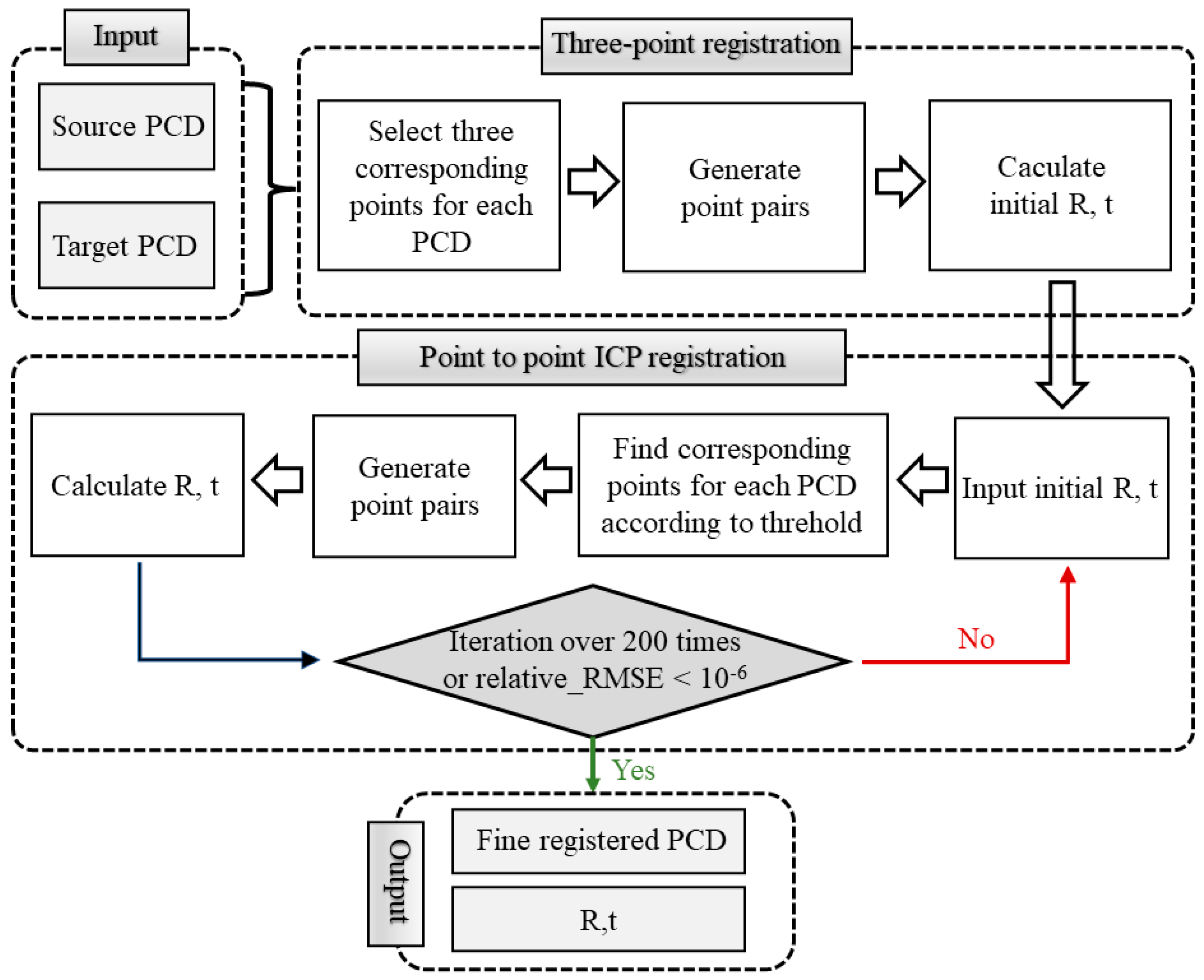
Figure 1. Registration process. Note: ICP: iterative closest point; PCD: point cloud data; relative_RMSE: relative root-mean-square error.
Buildings 13 01473 g001
Figure 2. Registration error. Note: Once the source and target point clouds were aligned using the predetermined transformation matrix R and transformation vector t, the mean distances between all point pairs were calculated to generate the registration error value for each point pair. PCD: point cloud data.
Buildings 13 01473 g002
Figure 3. Finely registered point cloud data models and voxel models. Note: For each scenario, the finely registered model (original point cloud data) was downsampled into 10 point clouds at different resolutions. The mesh model was also converted into 10 voxel models with different voxel sizes.
Buildings 13 01473 g003
Figure 4. Relationship between the voxel model and voxel coordinate system. Note: Vo (p, j, q) represents the coordinates of the voxel coordinate system origin in the world coordinate system. The voxel side length divided in the voxel coordinate system is equal to the voxel side length (d) of the voxel model. I (e, d, f) is the position index of the voxel in the voxel coordinate system.
Buildings 13 01473 g004
Figure 5. The defining of the occupied voxels. Note: A voxel is defined as occupied if the distance between at least one point in the point cloud and the voxel centre is less than half of the voxel edge length (d/2); otherwise, it is considered unoccupied. The sphere within the voxel can be understood as the point cloud search range formed by taking the voxel centre as the origin and half of the voxel size as the radius.
Buildings 13 01473 g005
Figure 6. Bond University’s sustainable building.
Buildings 13 01473 g006
Figure 7. FARO Freestyle 2 (right); FARO Focus S70 (left); DJI Mini 3 Pro (top).
Buildings 13 01473 g007
Figure 8. (a,b) Application of the laser level to ensure markers were at the same height; (c) use of a laser rangefinder to measure the distance between each group of markers.
Buildings 13 01473 g008
Figure 9. Ground truth model provided by Bond University. Note: From left to right, the sequence illustrates the process of converting the as-built BIM model into a voxel model.
Buildings 13 01473 g009
Figure 10. Finely registered point cloud data from (a) Scenario 1, (b) Scenario 2 and (c) Scenario 3.
Buildings 13 01473 g010
Figure 11. Scan plan in Scenario 2 for (a) Level 1, (b) Level 2, (c) Level 3. Note: The red points represent the placement positions of the FS70. The red-filled areas indicate closed areas that could not be accessed or were too narrow for the placement of the FS70.
Buildings 13 01473 g011
Figure 12. Scan plans in Scenario 3 for (a) Level 1, (b) Level 2, (c) Level 3. Note: The red points represent the placement positions of the FS70. The red-filled areas indicate closed areas that could not be accessed. The purple regions represent the scanning areas of the FF2.
Buildings 13 01473 g012
Figure 13. (a) DJI Mini 3 Pro flight trajectory and (b) the point cloud generated using images.
Buildings 13 01473 g013
Figure 14. Registration error values from each scenario.
Buildings 13 01473 g014
Figure 15. Scan overlap rates for each scenario.
Buildings 13 01473 g015
Figure 16. (Left) Specific point errors corresponding to their ground truth values. (Right) Ratio of point errors to all ground truth values.
Buildings 13 01473 g016
Figure 17. Coverage rate for different scenarios; from left to right: Scenario 1, Scenario 2 and Scenario 3.
Buildings 13 01473 g017
Figure 18. Colour models and histograms showing the distance between each point in the PCD and the ground truth model (top: Scenario 1; middle: Scenario 2; bottom: Scenario 3). Note: C2M: point cloud-to-ground truth model.
Buildings 13 01473 g018
Figure 19. Adjusted coverage rate values for (a) Scenario 1, (b) Scenario 2 and (c) Scenario 3. (d) PCP rate obtained from the original point cloud at a corresponding distance from the mesh model.
Buildings 13 01473 g019
Table 1. Comparison of different point cloud data collection methods.
Advance Scan PlanningTLSTLS + MLS + UAVDP
NoScenario 1
YesScenario 2Scenario 3
Note: TLS: terrestrial laser scanning; MLS: mobile laser scanning; UAVDP: unmanned aerial vehicle-based digital photogrammetry.
Table 2. Registration error results.
Evaluation MetricScenario 1Scenario 2Scenario 3
Range (mm)0.2–13.20.2–11.40.3–18.9
Mean value (mm)4.392.795.63
Standard deviation (mm)3.192.794.11
Table 3. Regression analysis results for registration error.
Coefficientt-Valuep-Value
Scenario 11.60 ***3.190.002
Scenario 32.84 ***5.750.000
Constant2.79 ***8.070.000
Note: Scenario 2 was used as the control group. *** p < 0.01; ** p < 0.05; * p < 0.1.
Table 4. Scan overlap rate results.
Evaluation MetricScenario 1Scenario 2Scenario 3
Range (%)13.5–56.316.0–71.515.0–59.6
Mean value (%)26.9232.1730.07
Standard deviation (%)8.6410.807.67
Table 5. Regression analysis for scan overlap rate.
Coefficientt-Valuep-Value
Scenario 1−5.24 ***−3.890.000
Scenario 3−2.10−1.570.116
Constant32.17 ***34.560.000
Note: Scenario 2 was used as the control group. *** p < 0.01; ** p < 0.05; * p < 0.1.
Table 6. Point error results.
Evaluation MetricScenario 1Scenario 2Scenario 3
Range (mm)0–70–50–16
Mean value (mm)2.041.305.62
Standard deviation (mm)1.681.223.74
Table 7. Regression analysis for point errors.
Coefficientt-Valuep-Value
Scenario 10.741.500.136
Scenario 34.32 ***8.750.000
Constant1.30 ***3.720.000
Note: Scenario 2 was used as the control group. *** p < 0.01; ** p < 0.05; * p < 0.1.
Table 8. Coverage rate results.
Evaluation MetricScenario 1Scenario 2Scenario 3
Range (%)5.10–54.799.01–61.124.00–64.79
Mean value (%)40.0847.0642.39
Standard deviation (%)14.3213.5717.16
Table 9. Adjusted coverage rate results.
Evaluation MetricScenario 1Scenario 2Scenario 3
Range (%)21.10–68.0331.56–73.8922.35–83.00
Mean value (%)59.9967.5072.79
Standard deviation (%)10.337.8214.02
Table 10. Regression analysis for adjusted coverage rate.
Coefficientt-Valuep-Value
Scenario 1−7.52 ***−4.830.000
Scenario 35.29 ***3.390.001
Constant67.51 ***61.240.000
Note: Scenario 2 was used as the control group. *** p < 0.01; ** p < 0.05; * p < 0.1.
Disclaimer/Publisher’s Note: The statements, opinions and data contained in all publications are solely those of the individual author(s) and contributor(s) and not of MDPI and/or the editor(s). MDPI and/or the editor(s) disclaim responsibility for any injury to people or property resulting from any ideas, methods, instructions or products referred to in the content.