Article

Application of BIM to Rebar Modeling of a Variable Section Column

1
School of Civil Engineering and Communication, North China University of Water Resources and Electric Power, Zhengzhou 450046, China
2
Engineering Technology Research Center for Structural Vibration Control and Health Monitoring of Henan Province, Zhengzhou 450046, China
*
Authors to whom correspondence should be addressed.
Buildings 2023, 13(5), 1234; https://doi.org/10.3390/buildings13051234
Submission received: 29 March 2023 / Revised: 4 May 2023 / Accepted: 6 May 2023 / Published: 8 May 2023
(This article belongs to the Section Construction Management, and Computers & Digitization)

Abstract

:
A planar construction drawing is usually used to guide the construction of reinforced concrete structures in the construction industry. Due to a lack of effective technical methods, the accuracy of rebar engineering lofting is insufficient. The rejection rate of rebar is high, which results in high processing costs. Under the background of intelligent construction and BIM technology, the prefabricated factory adopts an automatic production mode to concentrate on steel bar processing, which improves production quality and processing efficiency and reduces production costs. Based on Revit secondary development, using the C# programming language, combined with the Revit API development interface, an automatic 3D modeling plugin for a reinforced concrete variable cross-section column is developed. The BIM model of steel bars is quickly generated, and the engineering quantity of steel bars is automatically calculated, which saves time for the designer to build the BIM model. It is conducive to the automatic assembly and intelligent construction of reinforced concrete engineering, which promotes the information and intelligent development of reinforced concrete structure construction.

1. Introduction

In the Chinese architectural design industry, a planar construction drawing [1] is widely used to express the method of construction drawing, which is a reference standard for designer to design construction structures. With the further application of Building Information Model (BIM) technology, it is imperative to combine planar construction drawing with BIM technology [2,3]. In complex structure design, designers use a planar construction drawing to express designing extension. However, with the low readability of the drawing, it is difficult to be fully understood by construction workers. Therefore, integrating BIM technology into construction drawings of reinforced concrete structures can clearly present the steel bar lofting diagram, which is intuitive and simple. In addition, the accuracy of the steel bar is strengthened. This measure can not only enhance the qualified rate of steel bar production but also improve the efficiency of construction [4,5,6].
At present, BIM technology has developed rapidly in the field of civil engineering, leading the wave of ideological change in the construction industry. Many scholars have carried out a great number of in-depth studies on BIM technology. Carvalho [7] adopted Autodesk Revit to create 18 different simulation schemes, developed a framework in Dynamo to automatically characterize the environmental impact and cost of the life cycle of a construction project, and automatically conducted LCA and LCC analysis in the early stage of a project to realize the application of BIM technology in the assessment of building sustainability. Zou [8] integrated the risk decomposition structure (RBS) of bridge projects into 3D/4D BIM, established a connection between risk data and BIM, and proposed a new method of risk visualization and information management. Li [9] proposed an object-oriented database (BIM-ooDB) for a BIM back-end data system that can be shared for BIM front-end applications, established a complete system configuration, and realized the storage of all information on the project life cycle into a unified BIM model. Chen [10] classified the characteristics of building components according to a geometric model and provided an effective mechanism for data transmission from BIM to AR/VR, improving the overall shape consistency and frame rate in AR/VR applications. Kim [11] built prototypes based on the Robot Operating System (ROS), which enables BIM to integrate the construction and robotics domains using robotic task planning to plan the operation of autonomous robots in construction projects. Yoon [12] developed an AR construction work support system based on BIM that provides 3D models and work-related information in AR at the correct scale, size, and position. Samad [13] developed and implemented a technology roadmap required by the construction industry by investigating the implementation status of construction technology, which can provide policymakers with a framework for industry or company strategy in the next 10 years. Jiang [14] used BIM for construction simulation and made reliable construction management plans, which help with the deployment of intelligent building construction processes in many aspects and improve the efficiency of building construction management. Mario [15] integrated a BIM-based approach into the Product–Service System (PSS) environment, improving the management of maintenance operations for construction equipment. Using a game engine as a platform, Carlos [16] used BIM to facilitate the development of construction simulation models, implementing a proposed framework for integrating BIM and construction simulation that reduces the skill, effort, and time required to develop simulation simulations and achieve model reuse. Gao [17] determined the installation sequence and positioning of each prefabricated component using a BIM visual programming algorithm and generated the operation path parameters for each component installed with the manipulator based on the RT-Star algorithm, realizing the obstacle avoidance of the assembly path suitable for architectural application scenarios. Wang [18] analyzed different printing requirements and printing methods, using the C# programming language to automate repetitive steps in the printing process in the background, which improved the printing output efficiency of the Revit model and simplified the printing process.
BIM has been widely used in various stages of construction projects [19,20]. In the planning stage, the application value of BIM is reflected in the aspects of site analysis, architectural planning, and scheme demonstration [21,22]. It can compare and simulate the lighting, layout, vision, and ergonomics of different design schemes, so as to evaluate the cost, time, and income of different schemes in many aspects and provide a reliable basis for the owner’s final scheme selection. In the design stage, designers realize a visual design with virtual three-dimensional graphics, which help to improve design efficiency [23,24,25]. The components drawn with BIM have the characteristics of parameterization. The attribute data of each component stored in the BIM platform can provide the basis for collaborative design between different professions. BIM can also realize data sharing among multiple specialties, promote collaboration among specialties, and improve design efficiency and drawing quality. In the construction stage, Revit, developed by Autodesk in Dallas, America, is used to simulate the construction in advance, which can identify problems that may be encountered in the actual operation in advance and prevent them in advance [26]. In the operation and maintenance stage, BIM technology can realize the inheritance management of space, facilities, hidden works, emergencies, energy conservation, and emission reduction and provide convenience for the operation and maintenance of the project in many aspects [27,28,29].
In this paper, Revit is selected as the application platform for BIM technology, discussing research on the method of variable cross-section column steel bars in the design stage. Using the previous structural design and model creation, it is necessary to first cut the plane and inside of a 3D model and then manually draw the steel bar in the cut view, which is more complicated. So, using Revit 2018 software as the secondary development platform, research on the automatic generation of a steel bar model in a complex variable cross-section column is carried out. According to the local coordinate system of the column, the control points on the longitudinal rebar are precisely located in the variable section column. The rebar model is generated using these control points. Using object-oriented C# programming language, combined with the Revit API development interface and Visual Studio 2019 programming tool, an automatic generation for the 3D parametric modeling of rebar is developed with a variable cross-section column. Based on the automatic generation of the parametric rebar model, a corresponding program is written to realize the automatic export of 2D steel bar construction drawings. The processing information on the steel bar model is extracted from the BIM model automatically generated with the column and rebar and then exported into an Excel table of steel bar engineering quantity, which is convenient for the automatic processing and assembly of rebar engineering.

2. Methods

A variety of BIM software can be combined with Revit software to achieve different functions. For example, Revit can be combined with the surface modeling software Rhino 6.0 to create complex surface models such as irregular surface models. Revit is combined with the steel structure modeling software Tekla 2017 to import the steel structure model created using Tekla into Revit for model integration and to complete other related BIM applications such as pipe comprehensive optimization. Revit is combined with the building, light, and thermal analysis software Ecoect 2010 to import the Revit model into Ecotect for acoustic, light, and thermal environment analysis. Revit is combined with the building roaming and simulation software Navisworks 2018 to import the Revit model into Navisworks, making the Revit model lightweight and free from the limitations of computer hardware. Table 1 shows the use of these software programs in combination with Revit. Therefore, this paper chooses Revit software as the object for Revit secondary development.
The software used in Revit secondary development includes Revit, Visual Studio2019, and Revit SDK. Revit SDK is the official software development package of Revit, including Add-In Manager, Revit Lookup, RevitAPI.chm, and other helpful tools. Revit Lookup is the official plugin provided by Autodesk. Developers can use it to query the attributes and parameters of components without writing code, which helps developers understand the parameter types and how to obtain parameters during the development process. Add-in Manager is the official plugin of Autodesk, which is used to load the program written using Visual Studio to operate Revit. Developers can modify the code and run it again without restarting Visual Studio or Revit. RevitAPI.chm is a help document for developers to query the classes, methods, and corresponding namespaces needed for development. The basic process for Revit secondary development is shown in Figure 1.
The process includes creating a class library using .NetFramework in Visual Studio2019 and naming it. Next, the user adds the RevitAPI.dll and RevitAPIUI.dll dynamic link libraries by reference into the solution manager column. The last step is to add the user command in the programming interface and refer to the related namespace in Revit.
Revit API is a development tool based on Revit, which needs to work when Revit is running. Revit API can be used to access graphical data and parameter data. The model elements can be created, modified, and deleted. The developed plugin can enhance UI and automate repetitive work, which integrates third-party applications to complete tasks such as linking to external databases and converting data to analytical applications. To access and extend Revit using Revit API, developers need to implement special interfaces in the plugin. These interfaces include IExternalCommand and IExternalApplication. The IExternalCommand is an external command implementation interface provided by Revit API for developers to extend Revit using external commands. If Revit does not run any command, then loading the command using the Add-in Manager will run the related program in Revit and the IExternalComand will be activated. After the IExternalCommand command is activated, the Execute function is executed, which requires an Autodesk.Revit.UI.Result.Succeeded return value to indicate the successful execution of IExternalCommand. If it is not successfully executed, the system will revoke all operations and modification commands made with the execution program. Compared with the external command, the implementation of the external application is more direct and needs to be registered in the Add-in module. Then, External commands can be created in the Add-in module. External applications start with Revit programs and exit with Revit shutdowns. Therefore, the implementation of this function requires rewriting the OnStartup() function and the OnShutDown() function after implementing the interface of IExternalApplication.
Using the functions for steel bar generation, there are five ways to create steel bars. The parameters in these functions are different. These functions are as follows:
(1)
Rebar.CreateFreeForm() creates a free-form rebar that can have constraints.
(2)
Rebar.CreateFreeForm() creates a free-form rebar that will be unconstrained.
(3)
Rebar.CreateFromCurves() creates a new instance of a shape-driven rebar element within the project.
(4)
Rebar.CreateFromRebarShape() creates a new instance of a shape-driven rebar element within the project.
(5)
Rebar.CreateFromCurvesAndShape() creates a new shape-driven rebar, as an instance of a rebar shape.
Since the steel bars are not regular in a variable cross-section column, there is no family type of variable cross-section column steel bars in Revit. Therefore, the third function is chosen to create steel bars.
To improve the usability and user experience of the program, WPF (Windows Presentation Foundation) technology is used to develop a more visual interactive interface. In this interactive interface, the type and diameter of the steel bar, the bend hook of the steel bar, the composite way of the stirrup, and the thickness of the protective layer are displayed in the dropdown menu of the interactive UI interface, which is convenient and intuitive for the user. The WPF interactive interface is shown in Figure 2.

3. Generation of a Rebar Model

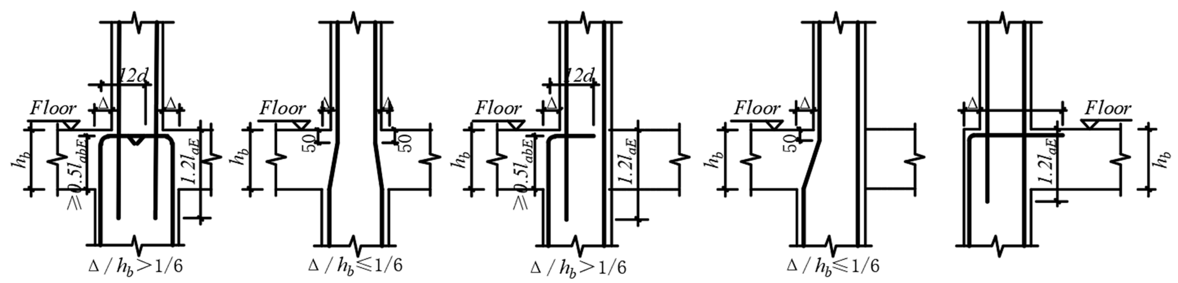
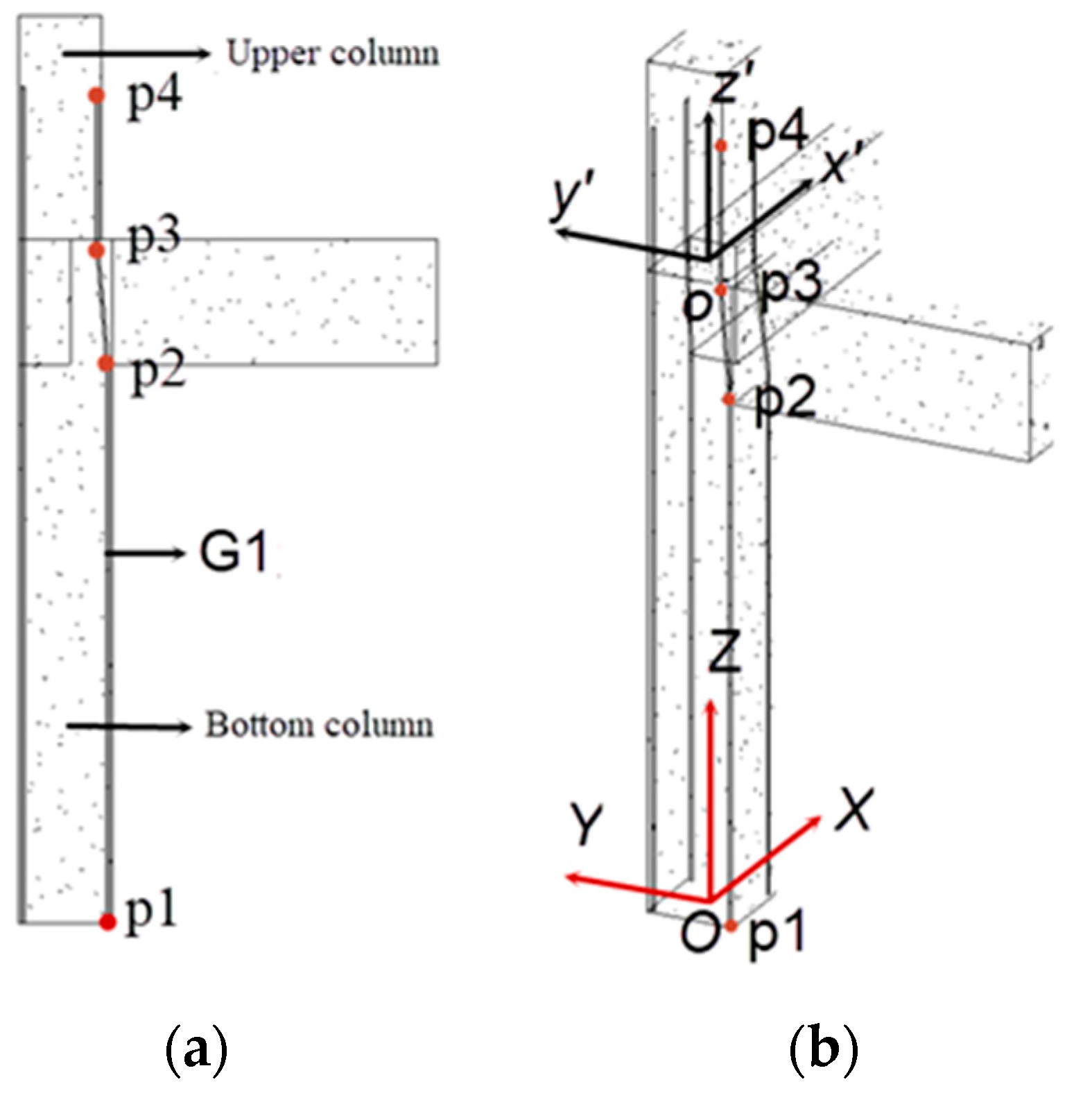
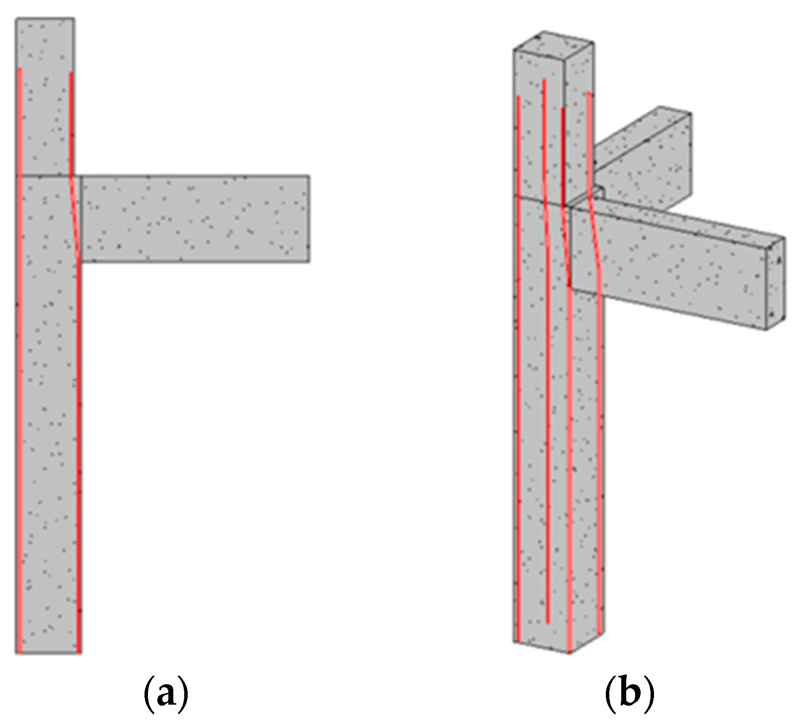
3.1. Generation of Longitudinal Corner Rebar with Variable Section of Column

In actual engineering, the shape of the steel bar is not a standard straight line. In the longitudinal rebar at the variable cross-section position of the column, there are bending and end hooks. The variable cross-section column is more widely used in practical engineering applications. The shape of the steel bar determines its curve trajectory according to the type of the variable cross-section column. The basic idea of generating variable cross-section longitudinal rebar using this program is to obtain the local coordinate system of the upper column and bottom column, respectively, and determine the anchor point of the rebar in their local coordinate system. Then, the user uses the Line.CreateBound() function in Revit API to connect these registration points in turn into a curve, adds these curves to the List<Curve> collection, and uses the Rebar.CreateFromCurve() function to generate longitudinal rebar with variable sections from the curve information. The longitudinal rebar structure at the variable section position of the column is shown in Figure 3.
In Revit, all elements are determined based on the Revit global coordinate system. In the variable cross-section column, as shown in Figure 4, there are four control points for a single longitudinal rebar, namely p1, p2, p3, and p4, where p1 and p2 are determined based on the local coordinate system O-XYZ of the bottom column, and p3 and p4 are determined based on the local coordinate system o-x′y′z′ of the upper column. Using the Transform.Inverse.OfPoint() function, points based on these two coordinate systems can be converted into points in the Revit global coordinate system. Using the coordinate system O-XYZ as an example, we explain how to determine the positioning point of the steel bar.
Firstly, the position coordinates of the longitudinal rebar at the four corners on the bottom column are calculated, as shown in Figure 5.
The figure shows the bottom section of the structural column model. The section width of the structural column is b, the section height is h, and the center coordinates of the bottom of the structural column are X, Y, and Z. The thickness of the protective layer is c, the diameter of the stirrups is d g , the diameter of the longitudinal rebar is d z , and the numbering for the corner rebars is G1, G2, G3, and G4, respectively. Using corner rebar G1 as an example, the X, Y, and Z directions of G1 in the third quadrant below are calculated as follows.
x direction of G1:
x G 1 = b / 2 + c + d g + d g / 2
y direction of G1:
y G 1 = h / 2 + c + d g + d z / 2
z direction of G1:
z G 1 = c
The calculation method for the bottom coordinates G2, G3, and G4 is the same as that for G1, and their coordinate points are shown in Table 2.
The coordinate calculation for p3 and p4 based on o-x′y′z′ coordinate system is similar to the above algorithm. An example diagram showing the completed angular rebar is shown in Figure 6.

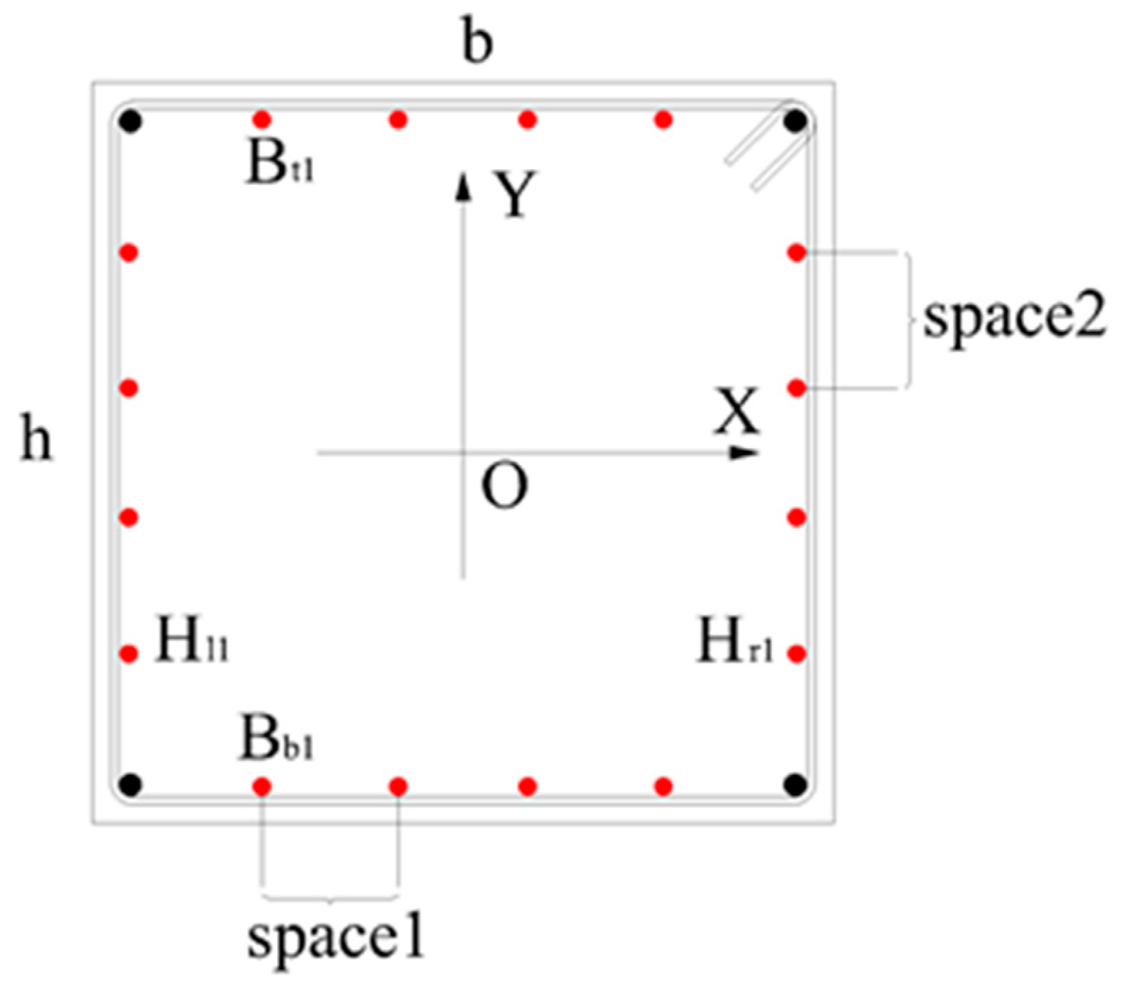
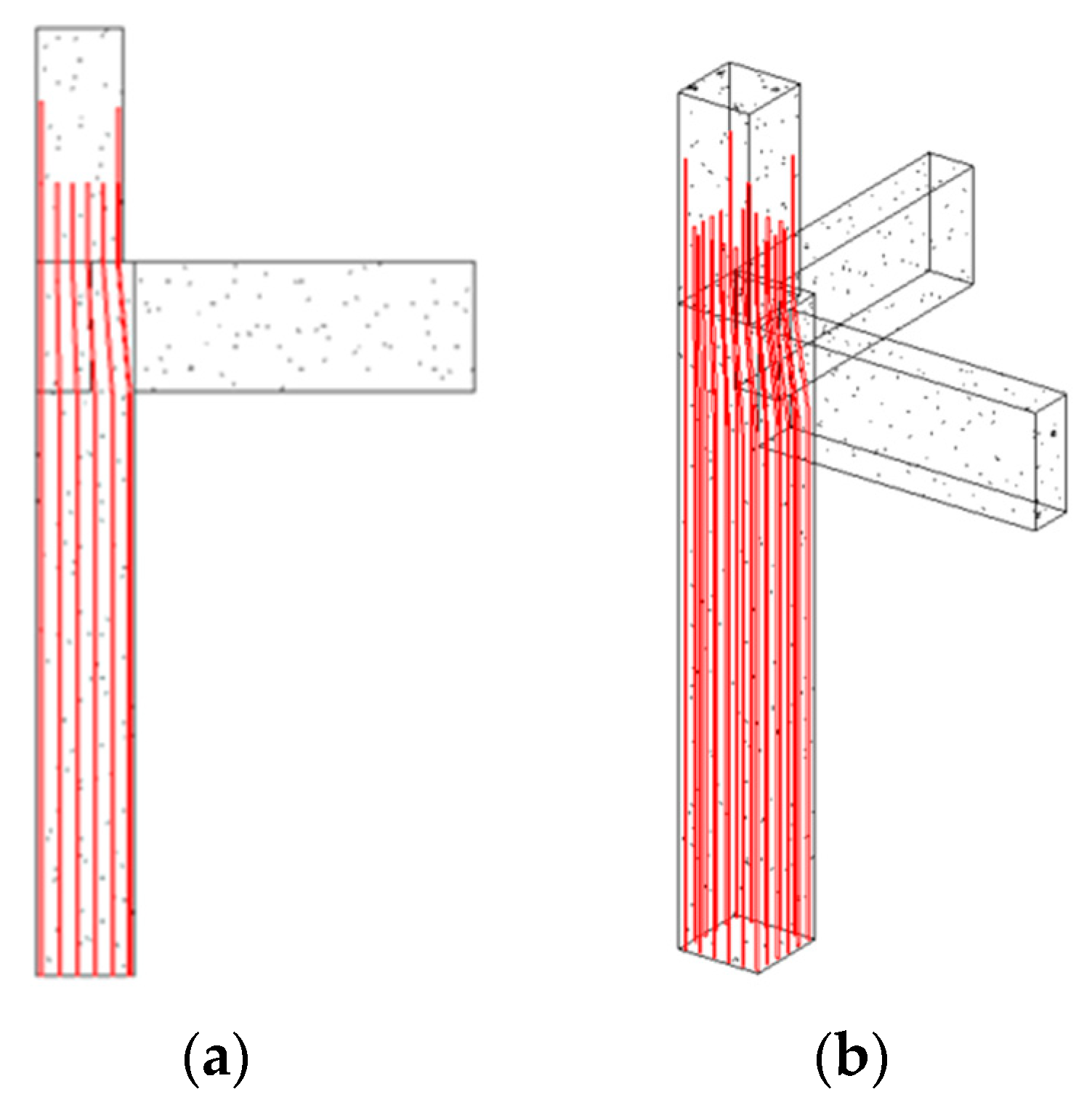
3.2. The Generation of Longitudinal Rebar for the Variable Section Column

The longitudinal side rebar can be created using the Rebar.CreateFromCurve() function, which needs four control points to generate a single longitudinal side rebar. Two of them are determined based on the bottom column coordinate system, and the other two are determined based on the upper column coordinate system. However, the calculation for the control points of the longitudinal edge rebar is different from that for the longitudinal angle rebar. As shown in Figure 7, the spacing between the two side rebars is determined by dividing the anchor points of the two corner rebars by the number of spaces between them. The thickness of the concrete protective layer is c, the diameter of the stirrups is d g , the diameter of the corner rebar is d z , and the diameter of the side rebar is d b . The spacing distance of the side rebar in h is space1, the spacing distance of the side rebar in b is space2, the number of side rebar in h is n h , and the number of side rebar in b is n b . The formula for calculating the spacing is as follows:
s p a c e 1 = b 2 c 2 d g d z n b + 1
s p a c e 2 = b 2 c 2 d g d z n h + 1
According to Formulas (4) and (5), the locations of all the side rebar can be conveniently calculated. Using the center of the bottom column below as the coordinate origin and setting the number of b side rebars and h side rebars as 4, the coordinates of the positioning point of the side rebar at the bottom are calculated. Let S 1 be the distance from the center of the corner rebar to the edge of the column, and S 2 be the distance from the center of the side rebar to the edge of the column.
S 1 = d z / 2 + d g / 2 + c
S 2 = d b / 2 + d g 2 / 2 + c
According to Formulas (6) and (7), the following coordinates of the control points can be calculated. The longitudinal side rebar coordinates of the bottom column are shown in Table 3.
The control point coordinates of the side rebar, which are based on the coordinate origin in the center of the bottom column, are different from those on the Z-axis, while these coordinates on the X-axis and Y-axis are the same. So, the coordinates of these control points can be easily calculated. The other two anchor points of a single-edge rebar are determined using the origin of the coordinates. The completed instances of the edge rebar are shown in Figure 8.

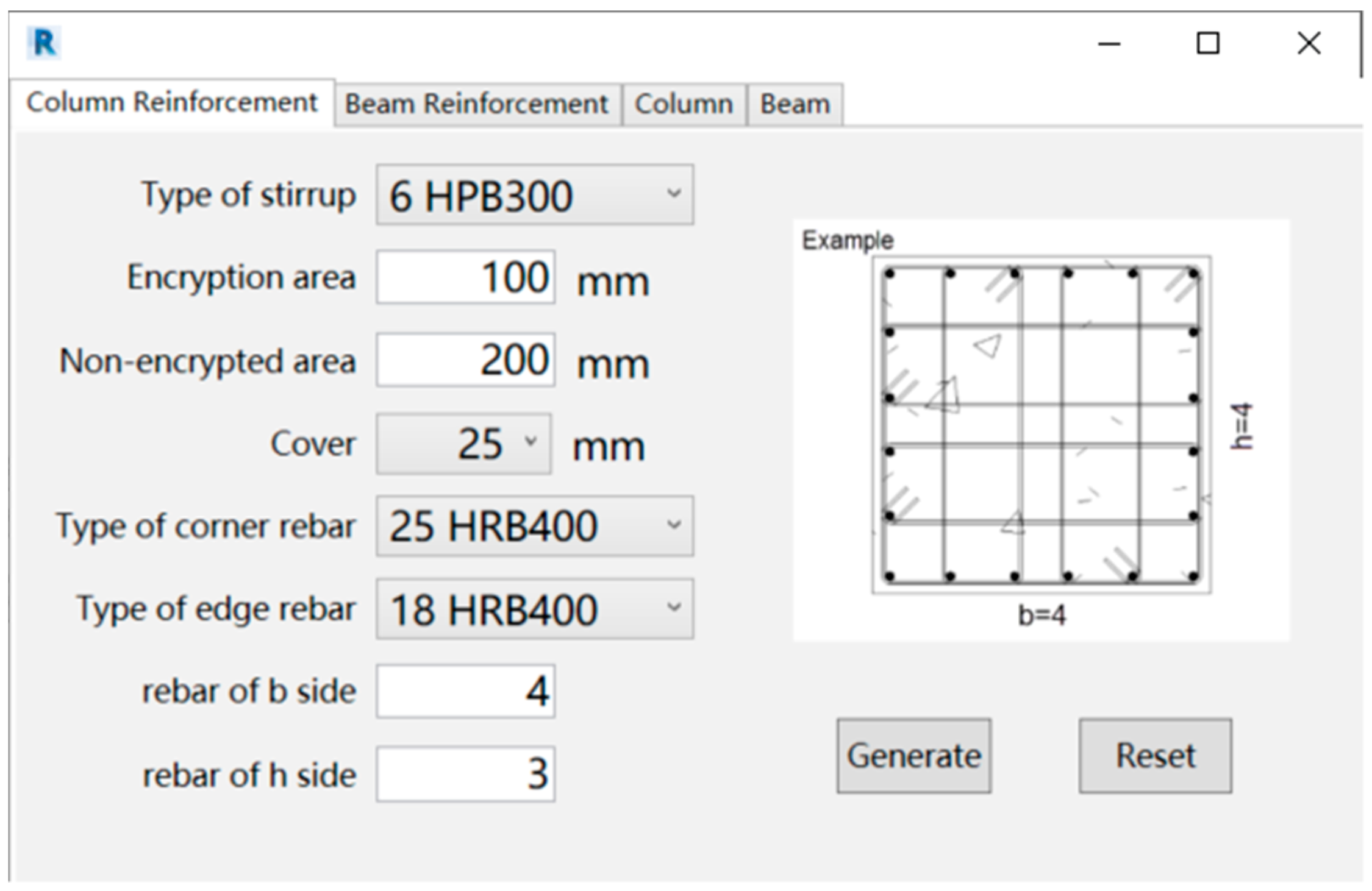
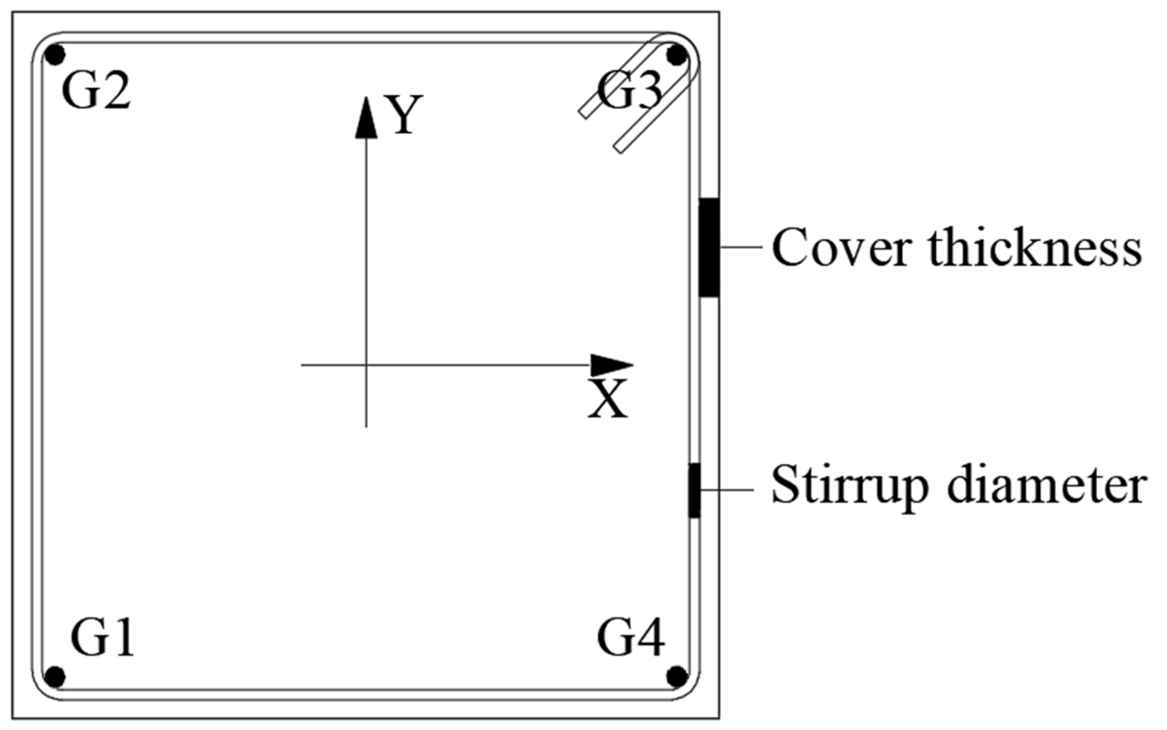
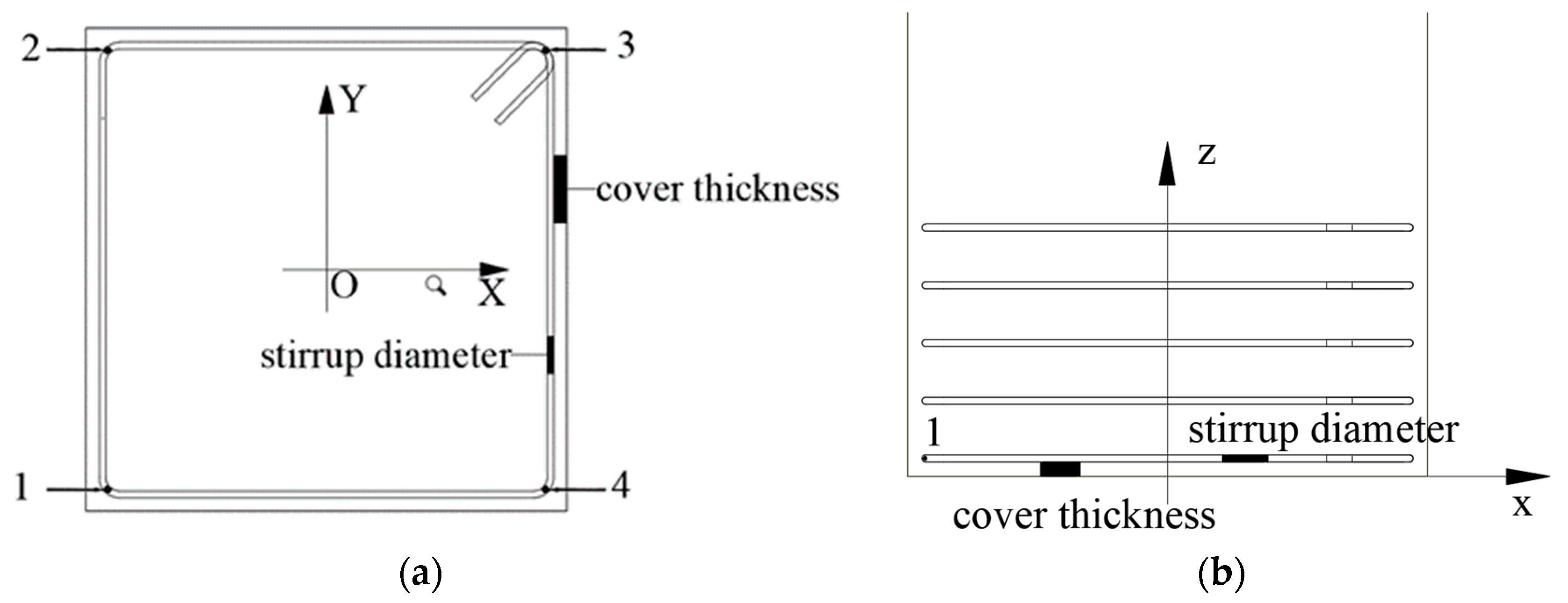
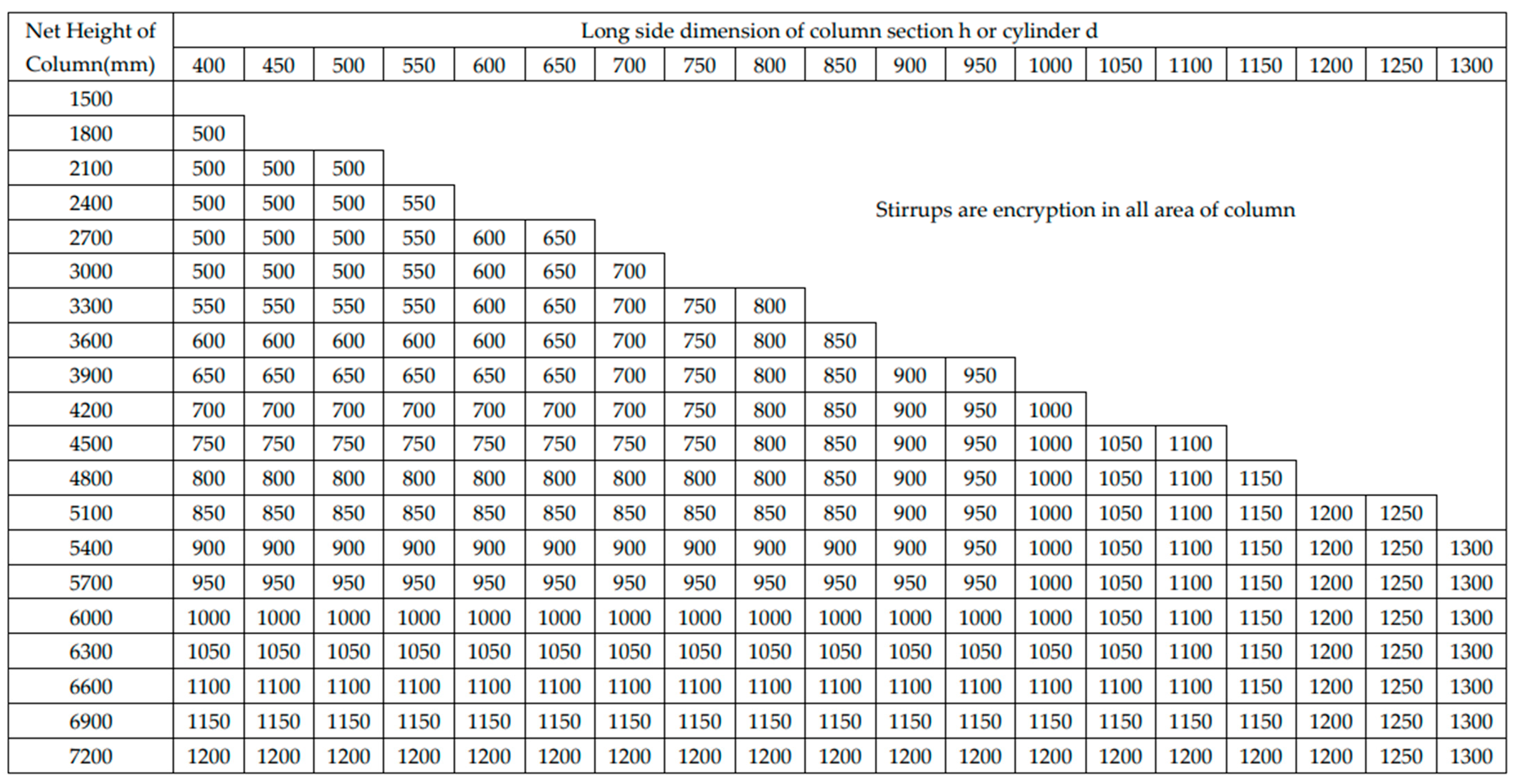
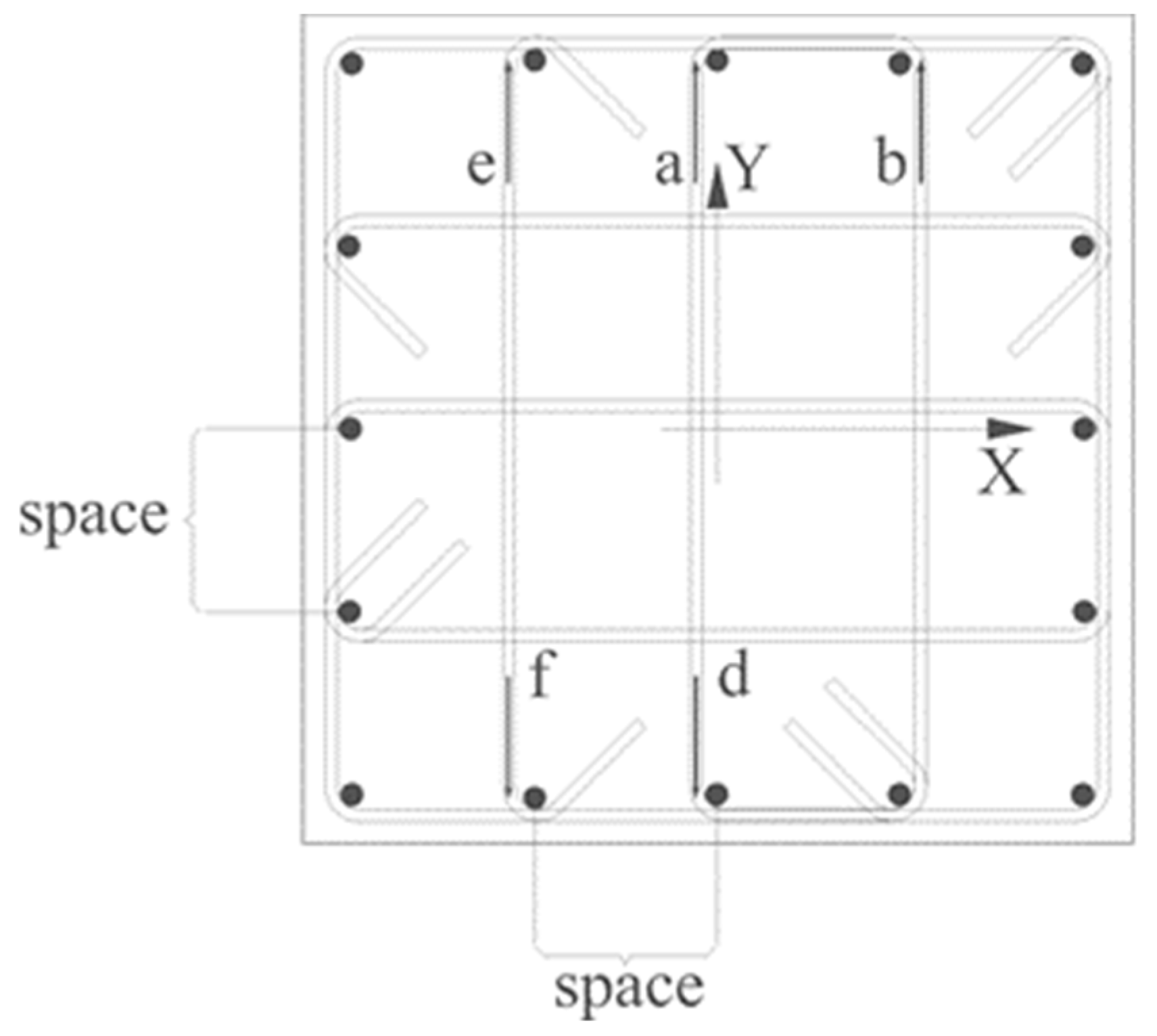
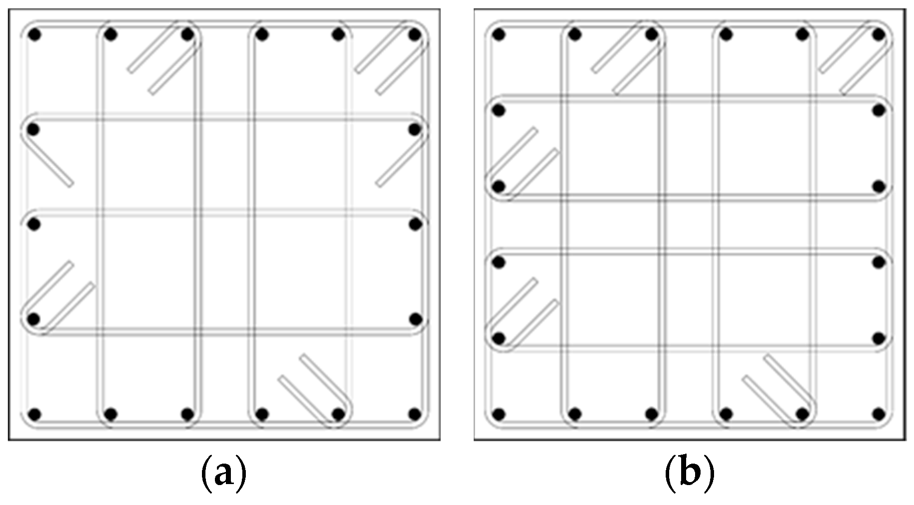
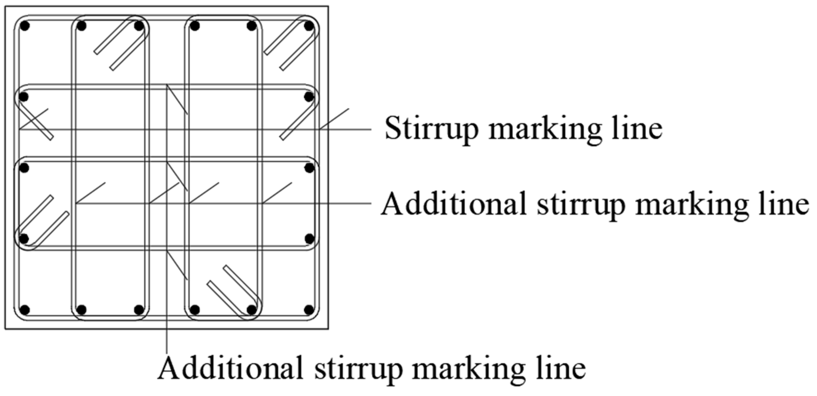
3.3. Generation of a Stirrup

The closed rectangular stirrup is represented as a quadrilateral with arc corners. The stirrup is described using parameter control points. A stirrup can be described by four points, which are 1, 2, 3, and 4, and a closed circular stirrup can be created according to the coordinates of the four points. The coordinates of the four corners of the stirrup are calculated by obtaining the origin coordinates of the structural column and the thickness of the protective layer. For example, using O as the origin of the coordinate, its X, Y, and Z axes are shown in Figure 9.
The thickness of the rebar protective layer is set as c, the diameter of the stirrup is d g , and the section width and height of the structural column are set as b and h, respectively. Then, the coordinates l x , l y of the corner point 1 in the lower left corner of the stirrup at the bottom of the structural column in the X- and Y-directions are as follows:
l x = b / 2 + c + d g / 2
l y = h / 2 + c + d g / 2
Point 1 also has a length in the Z-direction, which is the thickness of the protective layer of the steel bar plus half the diameter of the stirrup. l z is calculated as follows:
l z = c + d g / 2
The coordinates of points 2, 3, and 4 are shown in Table 4.
After the coordinates of the four points on the stirrup in the structural column are calculated, a line segment is created using the Line.createBound() function in Revit API by passing the coordinates of the two points into the parameters of that function. Then, the four-line segments are added to the List<Curve> collection by placing the four points end to end to form a closed quadrilateral wireframe. The List set of the four line segments is passed into the Rebar.CreateFromCurves() function with parameters such as stirrup style and stirrup hook. The result is a closed hoop. If the four line segments are not end-to-end, the program will report an error and cannot generate the stirrup.
After the single stirrup is created, it is also necessary to arrange it in the Z-axis direction. According to the planar construction drawing, it is necessary to consider whether the stirrups are encrypted and the encrypted and non-encrypted areas of the structural columns. The creation of both encryption and non-encryption area stirrups can be completed using a for loop. Considering the aseismic requirement, the height of the structure column can be determined according to the height selection table for the aseismic frame column in the code. As shown in Figure 10, linear interpolation can be used to calculate the height of the stirrup area when the corresponding column net height is not in the table.

3.4. Generation of Additional Stirrups

The number and form of additional stirrups are determined by the number of side rebars in the structural column. This program develops a calculation method based on the composite mode of the rectangular stirrup in the standard construction detail drawing of the column. The program can automatically match the required stirrup compound mode with the user input for the number of side rebars, which are automatically placed in the structural column. A schematic diagram showing the additional stirrups in the structural column is shown in Figure 11.
The side rebar in the structural column is arranged at the same spacing, and their positions have been determined. The placement of additional stirrups can be determined according to the position of the side rebar. An additional stirrup also takes the center of the structural column as its origin of coordinates. In the case of a double-leg hoop, it is determined using three corner points. In the case of a single-leg hoop, it is determined using two corner points. The anchor point of the additional reinforcement is located at the outer edge of the side rebar. By setting the interval of the side rebar as s, the thickness of the protective layer as c, the diameter of the additional stirrup as d f g , the diameter of the stirrup as d g , and the diameter of the side rebar as d z 1 , the coordinate of point a in the X-direction is as follows:
x a = d z 1 / 2 d f g / 2
The Y coordinate of point a is:
y a = h / 2 c d f g / 2
To prevent a collision between the additional stirrup and stirrup, it is necessary to stagger the additional stirrup and stirrup, so the coordinate of point a in the Z-direction is as follows:
z a = c + d g + d f g / 2
Compared with point a, point b has an extra edge bar spacing plus the diameter of the edge bar in the X-axis direction, and its coordinates in the Y- and Z-directions are the same as those of point a. Therefore, the coordinate of point b in the X-direction is as follows:
x b = s + d z 1 / 2 + d f g / 2
Point d is symmetric with respect to the Y-axis with respect to a, and the coordinates of point d can be obtained by simply taking the negative Y-axis coordinates of a. The one-limb hoop is determined using two points. Point e and point b are symmetric about the X-axis of the coordinate system. The coordinates of point e can be obtained by using the X-axis coordinate of b as a negative number. Point f and point e are symmetric about the X-axis. The coordinates of point f can be obtained by using the coordinates on the Y-axis of point e as negative numbers. Similarly, steel bars in other positions can be obtained using similar calculations. The above is a 5 × 5 form of stirrup composite method. In the rectangular stirrup composite method for column annotation construction detail drawings, there are many other composite methods, such as the 6 × 5 shape, 6 × 6 shape, etc., as shown in Figure 12. The anchorage point calculation process for these different composite stirrups is the same. In the actual project, the program can automatically match the appropriate stirrup compound mode according to the number of edge rebars input by the user.

4. The Statistics of Steel Bar Quantities and the Generation of Steel Bar Marks

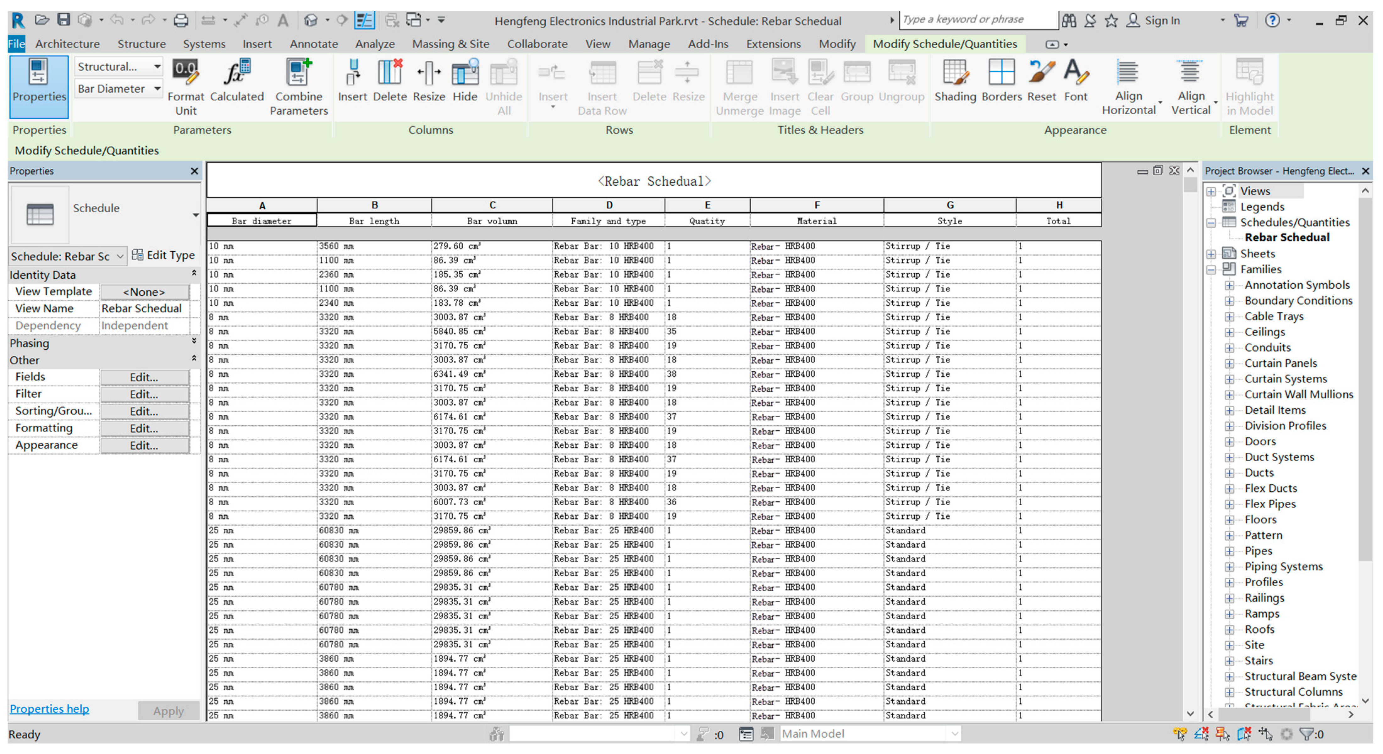
4.1. Revit Schedule Function and the Statistics of Steel Bars Quantities

Revit provides the user with an engineering quantity statistics tool called the “detail schedule”, which can realize the statistical function for the component quantity and related parameters for users.
By looking at the Revit API document, the statistics for the steel bar quantities schedule can be created using ViewSchedule.CreateSchedule() function. This function obtains two parameters: the Revit document and the type of Id needed to create the schedule. The Revit Lookup command is run to query the type of Id for the steel bar project list. It is the BuiltInCategory.OST_Rebar enumerated type. After the schedule of quantities is created, there is no content. So, it is necessary to add specific content to the schedule of quantities. For example, steel bar type, steel bar length, steel bar diameter, and steel bar strength grade are added to the schedule. A detailed schedule of steel bar quantities is shown in Figure 13.

4.2. Generation of Rebar Marks

To generate rebar marks, the user filters out visible elements of the family type Rebar in the specified profile view using the FilteredElementCollector filter, stores the elements in the IList<Rebar> collection, and then continues traversing the IList<Rebar> collection. Using traversing, the type of rebar that gets all visible in the view is the stirrup of the StirrupTie. Stirrup is an entity in Revit and cannot be used as a reference object directly. Therefore, a stirrup is taken as a sample of the reference object. Using the Rebar.GetCenterlineCurves() function, the user can convert all the stirrup Curves stored in the IList<Curve> collection. This function can obtain the control line of the stirrup, traverse the longitudinal stirrup, and use Line.Origin function to obtain the four anchor point coordinates of the double-limb hoop. Starting at the top left of the stirrup, it gathers four coordinates counterclockwise. The single-leg hoop obtains two anchor coordinates. The coordinates of the middle points on each side of the stirrup can be obtained, and the coordinates on both ends of the line segment to be drawn can be deduced. The Line.CreateBound() function is used to draw the line segment, and the Created.NewDetailCurve() function is used to generate the annotated line. Next, the user draws a diagonal segment at the intersection of the marked line and the stirrup and highlights it. Steel bar marking is shown in Figure 14.
After the steel bar marking line information on the structural column is generated, the current view is exported to CAD format using the Document.Export() function. The DetailLevel property is used to set the current view to fine mode, and then the DisplayStyle property is used to set the current view to wireframe mode. The exported CAD drawing is set to wireframe mode, which can clearly display the number of longitudinal steel bars, the position of the stirrup, and other information. The exported CAD drawing can be named using the current Revit view name and then adding “Rebar structure Drawing” behind it.

5. Conclusions

(1)
Using the C# programming language combined with Revit secondary development technology and the planar construction drawing, an automatic generation program for a steel bar parameter model is written. The generation of a longitudinal rebar model, stirrups in the encryption area, and stirrups in the non-encryption area are realized using the parameter-driven rebar model in a variable cross-section column. Users can choose the diameter and type of rebar according to their needs. They can also set the spacing of stirrups and the combination of additional stirrups. To a large extent, the repetitive work is reduced, and the modeling efficiency and accuracy are improved. This avoids the problem of inaccurate and nonstandard models caused by human errors.
(2)
Combined with WPF technology, the program operation interface was developed to increase the maneuverability of the program, which realized the automatic export of 2D steel bar CAD drawings and steel engineering quantities from a 3D model of steel bars and completed the forward design program from a 3D model to 2D drawings. The forward drawing of rebar engineering can improve the work efficiency of designers. This study provides a reference for subsequent research on the automatic forward design of steel bar engineering.

Author Contributions

Conceptualization, S.L. (Shushan Li), A.C. and W.X.; methodology, Y.S., J.H. and S.L. (Siyuan Li); software, Y.S., J.H. and S.L. (Siyuan Li); validation, Y.S., H.L. and S.L. (Shushan Li); formal analysis, Y.S.; investigation, W.X.; resources, S.L. (Shushan Li); data curation, Y.S. and S.L. (Shushan Li); writing—original draft preparation, S.L. (Shushan Li) and Y.S.; writing—review and editing, Y.S., S.L. (Shushan Li) and H.L.; visualization, Y.S.; supervision, A.C. and W.X.; project administration, Y.S.; funding acquisition, A.C. and W.X. All authors have read and agreed to the published version of the manuscript.

Funding

This research was funded by the National Natural Science Foundation of China (No. 52179133, No. U1404526).

Institutional Review Board Statement

Not applicable.

Informed Consent Statement

Not applicable.

Data Availability Statement

Data are contained within the article.

Conflicts of Interest

The authors declare no conflict of interest. The funders had no role in the design of the study; in the collection, analyses, or interpretation of data; in the writing of the manuscript; or in the decision to publish the results.

References

  1. 16G101-1; Construction Drawing of Concrete Structure, Planar Overall Representation Method Drawing Rules and Construction Details. China Plan Publishing Press: Beijing, China, 2016.
  2. Carvalho, J.P.; Bragança, L.; Mateus, R. A Systematic Review of the Role of BIM in Building Sustainability Assessment Methods. Appl. Sci. 2020, 10, 4444. [Google Scholar] [CrossRef]
  3. Wang, X.W.; Yu, H.; Yang, P. Analysis of the rational application of BIM technology in building structure design. Intell. Build. Smart City 2022, 11, 111–113. [Google Scholar] [CrossRef]
  4. Zheng, C.; Yi, C.; Lu, M. Integrated optimization of rebar detailing design and installation planning for waste reduction and productivity improvement. Autom. Constr. 2019, 101, 32–47. [Google Scholar] [CrossRef]
  5. Kwon, W.; Kim, H.; Ahn, H.; Park, U.Y.; Kim, C.K.; Cho, H. Analysis of BIM-Based Quantity Take-Off in Simplification of the Length of Processed Rebar. Appl. Sci. 2023, 13, 2468. [Google Scholar] [CrossRef]
  6. Lee, D.; Son, S.; Kim, D.; Kim, S. Special-Length-Priority Algorithm to Minimize Reinforcing Bar-Cutting Waste for Sustainable Construction. Sustainability 2020, 12, 5950. [Google Scholar] [CrossRef]
  7. Carvalho, J.P.; Villaschi, F.S.; Bragança, L. Assessing Life Cycle Environmental and Economic Impacts of Building Construction Solutions with BIM. Sustainability 2021, 13, 8914. [Google Scholar] [CrossRef]
  8. Zou, Y.; Kiviniemi, A.; Jones, S.W.; Walsh, J. Risk Information Management for Bridges by Integrating Risk Breakdown Structure into 3D/4D BIM. KSCE J. Civ. Eng. 2019, 23, 467–480. [Google Scholar] [CrossRef]
  9. Li, S.D.; Xu, Z.D. System Configuration Design of BIM Object-Oriented Database for Civil Engineering. J. Constr. Eng. Manag. 2022, 148, 04022130. [Google Scholar] [CrossRef]
  10. Chen, K.; Chen, W.; Cheng, J.C.P.; Wang, Q. Developing Efficient Mechanisms for BIM-to-AR/VR Data Transfer. J. Comput. Civ. Eng. 2020, 34, 04020037. [Google Scholar] [CrossRef]
  11. Kim, S.; Peavy, M.; Huang, P.C.; Kim, K. Development of BIM-integrated construction robot task planning and simulation system. Autom. Constr. 2021, 127, 103720. [Google Scholar] [CrossRef]
  12. Yoon, J.W.; Lee, S.H. Development of a Construction-Site Work Support System Using BIM-Marker-Based Augmented Reality. Sustainability 2023, 15, 3222. [Google Scholar] [CrossRef]
  13. Sepasgozar, S.M.E.; Khan, A.A.; Smith, K.; Romero, J.G.; Shen, X.; Shirowzhan, S.; Li, H.; Tahmasebinia, F. BIM and Digital Twin for Developing Convergence Technologies as Future of Digital Construction. Buildings 2023, 13, 441. [Google Scholar] [CrossRef]
  14. Jiang, Y. Intelligent Building Construction Management Based on BIM Digital Twin. Comput. Intell. Neurosci. 2021, 2021, e4979249. [Google Scholar] [CrossRef] [PubMed]
  15. Fargnoli, M.; Lleshaj, A.; Lombardi, M.; Sciarretta, N.; Di Gravio, G. A BIM-based PSS Approach for the Management of Maintenance Operations of Building Equipment. Buildings 2019, 9, 139. [Google Scholar] [CrossRef]
  16. Osorio-Sandoval, C.A.; Tizani, W.; Pereira, E.; Ninić, J.; Koch, C. Framework for BIM-Based Simulation of Construction Operations Implemented in a Game Engine. Buildings 2022, 12, 1199. [Google Scholar] [CrossRef]
  17. Gao, Y.F.; Shu, J.P.; Yu, K.; Jin, Z.F. Research on intelligent construction of lightweight structure robot based on BIM visual programming. J. Build. Struct. 2022, 43, 296–304. [Google Scholar] [CrossRef]
  18. Wang, P.; Gan, K.Y. A method to improve the output printing efficiency of BIM model based on Revit secondary development. Build. Struct. 2022, 52, 1982–1987. [Google Scholar] [CrossRef]
  19. Ma, X.; Xiong, F.; Olawumi, T.O.; Dong, N.; Chan, A.P.C. Conceptual Framework and Roadmap Approach for Integrating BIM into Lifecycle Project Management. J. Manag. Eng. 2018, 34, 05018011. [Google Scholar] [CrossRef]
  20. Olawumi, T.O.; Chan, D.W.M. Building information modelling and project information management framework for construction projects. J. Civ. Eng. Manag. 2019, 25, 53–75. [Google Scholar] [CrossRef]
  21. Mohammed, M.; Shafiq, N.; Al-Mekhlafi, A.-B.A.; Al-Fakih, A.; Zawawi, N.A.; Mohamed, A.M.; Khallaf, R.; Abualrejal, H.M.; Shehu, A.A.; Al-Nini, A. Beneficial Effects of 3D BIM for Pre-Empting Waste during the Planning and Design Stage of Building and Waste Reduction Strategies. Sustainability 2022, 14, 3410. [Google Scholar] [CrossRef]
  22. Marzouk, M.; Othman, A. Planning utility infrastructure requirements for smart cities using the integration between BIM and GIS. Sustain. Cities Soc. 2020, 57, 102120. [Google Scholar] [CrossRef]
  23. Rafindadi, A.D.; Shafiq, N.; Othman, I. A Conceptual Framework for BIM Process Flow to Mitigate the Causes of Fall-Related Accidents at the Design Stage. Sustainability 2022, 14, 13025. [Google Scholar] [CrossRef]
  24. Palumbo, E.; Soust-Verdaguer, B.; Llatas, C.; Traverso, M. How to Obtain Accurate Environmental Impacts at Early Design Stages in BIM When Using Environmental Product Declaration: A Method to Support Decision-Making. Sustainability 2020, 12, 6927. [Google Scholar] [CrossRef]
  25. Schneider-Marin, P.; Harter, H.; Tkachuk, K.; Lang, W. Uncertainty Analysis of Embedded Energy and Greenhouse Gas Emissions Using BIM in Early Design Stages. Sustainability 2020, 12, 2633. [Google Scholar] [CrossRef]
  26. Begić, H.; Galić, M. A Systematic Review of Construction 4.0 in the Context of the BIM 4.0 Premise. Buildings 2021, 11, 337. [Google Scholar] [CrossRef]
  27. Forcael, E.; Martínez-Rocamora, A.; Sepúlveda-Morales, J.; García-Alvarado, R.; Nope-Bernal, A.; Leighton, F. Behavior and Performance of BIM Users in a Collaborative Work Environment. Appl. Sci. 2020, 10, 2199. [Google Scholar] [CrossRef]
  28. Abideen, D.K.; Yunusa-Kaltungo, A.; Manu, P.; Cheung, C. A Systematic Review of the Extent to Which BIM Is Integrated into Operation and Maintenance. Sustainability 2022, 14, 8692. [Google Scholar] [CrossRef]
  29. Cao, Y.; Kamaruzzaman, S.N.; Aziz, N.M. Building Information Modeling (BIM) Capabilities in the Operation and Maintenance Phase of Green Buildings: A Systematic Review. Buildings 2022, 12, 830. [Google Scholar] [CrossRef]
Figure 1. Flowchart showing Revit secondary development.
Buildings 13 01234 g001
Figure 2. WPF interactive interface.
Buildings 13 01234 g002
Figure 3. Longitudinal rebar structure at the variable cross-section position of the column.
Buildings 13 01234 g003
Figure 4. (a) Front view showing the G1 corner rebar control points and (b) 3D view showing the G1 corner rebar control points.
Buildings 13 01234 g004
Figure 5. Location of the longitudinal corner rebar.
Buildings 13 01234 g005
Figure 6. (a) Front view showing the corner rebar instance and (b) 3D view showing the corner rebar instance.
Buildings 13 01234 g006
Figure 7. Location of longitudinal side rebar.
Buildings 13 01234 g007
Figure 8. (a) Side view showing the side rebar instance; (b) 3D view showing the side rebar instance.
Buildings 13 01234 g008
Figure 9. (a) Stirrup positioning point plane diagram and (b) stirrup positioning point elevation diagram.
Buildings 13 01234 g009
Figure 10. Height selection diagram showing the seismic frame column encryption area.
Buildings 13 01234 g010
Figure 11. Additional stirrup in the structural column.
Buildings 13 01234 g011
Figure 12. (a) Stirrup composite type 6 × 5 and (b) stirrup composite type 6 × 6.
Buildings 13 01234 g012
Figure 13. Schedule of steel bar quantities.
Buildings 13 01234 g013
Figure 14. Steel bar marking line.
Buildings 13 01234 g014
Table 1. Software property sheet.
Complex surface modelRevitCommon model design
RhinoSpecial-shaped surface model design
TeklaStructural steel design
Environmental analysisRevitModel design
EcotectAnalysis of sound, light, and thermal environments
Impact analysisRevitModel design
NavisworksVisual construction disclosure and report
Table 2. Corner control point coordinates of the bottom column.
PointXYZ
G2 b / 2 + c + d g + d g / 2 h / 2 c d g d z / 2 c
G3 b / 2 c d g d g / 2 h / 2 c d g d z / 2 c
G4 b / 2 c d g d g / 2 h / 2 + c + d g + d z / 2 c
Table 3. Longitudinal side rebar coordinates of bottom column sheet.
PointXYZ
B b i b / 2 + s p a c e 1 × i + S 1 ( i = 1,2 , 3,4 ) h / 2 + S 2 c
B t i b / 2 + s p a c e 1 × i + S 1 ( i = 1,2 , 3,4 ) h / 2 S 2 c
H l i h / 2 + s p a c e 2 × i + S 1 ( i = 1,2 , 3,4 ) b / 2 + S 2 c
H r i h / 2 + s p a c e 2 × i + S 1 ( i = 1,2 , 3,4 ) b / 2 S 2 c
Table 4. Coordinates of points 2, 3, and 4.
PointXYZ
2 b / 2 + c + d g / 2 h / 2 c d g / 2 c + d g / 2
3 b / 2 c d g / 2 h / 2 c d g / 2 c + d g / 2
4 b / 2 c d g / 2 h / 2 + c + d g / 2 c + d g / 2
Disclaimer/Publisher’s Note: The statements, opinions and data contained in all publications are solely those of the individual author(s) and contributor(s) and not of MDPI and/or the editor(s). MDPI and/or the editor(s) disclaim responsibility for any injury to people or property resulting from any ideas, methods, instructions or products referred to in the content.

