1. Introduction
Soil movements caused by tunneling activities in historic urban areas can cause potential damage to nearby historical masonry buildings when the ground deformation exceeds a particular limit [
1,
2,
3,
4]. Surface masonry buildings in the settlement trough can undergo structural distortion and rotation during the advancement of tunnel excavation [
5,
6,
7,
8], which leads to differential settlements and cracks in the building [
9,
10,
11,
12]. Compared with modern buildings built with reinforced concrete and based on deep foundations near tunnel excavations [
13,
14,
15,
16,
17], historical masonry buildings are more vulnerable to tunneling-induced soil disturbance mainly because of (i) the weak bond between the bricks and stones and (ii) the shallow foundations. On the one hand, the structure behaviors of historical masonry buildings inevitably deteriorate over decades or even centuries in urban environments [
18], partially caused by (a) chemical reactions of plaster and cement [
19,
20] and partially caused by (b) the weathering of the brick and stones [
21]. On the other hand, historical masonry buildings are usually based on shallow footings and, therefore, have to sustain the surface differential settlement, which could lead to serious cracks and even collapse considering the behavior of deteriorated structures. Therefore, the corresponding protection measurements of historical masonry buildings adjacent to tunneling have become critical issues that constrain tunneling design and project duration.
Considering the potential cracks caused by the differential settlement and the structural deterioration of historical buildings, protection measurements aim not only to reduce soil movements but also to strengthen the building stiffness. Tunneling-induced soil movements are strictly controlled by (i) using earth pressure balance machines to control the volume loss at the surface lower than 0.5% [
22,
23,
24] and (ii) installing rows of piles and diaphragm walls between the tunnel and historical sites to mitigate the impact of soil movement [
2,
25,
26,
27]. Furthermore, the stiffness of masonry buildings can be strengthened by reinforcing the foundations with micropiles [
24] and the masonry structures with steel-frame reinforcements [
23].
Table 1 presents the reported cases of historical masonry buildings with tunneling underneath, including the relative positions and the protection measurements. However, these protection measurements for historical masonry buildings are still far from routine since historical masonry buildings have different structure types under various ground conditions. Compared with the masonry buildings made of bricks and stones, there are numerous timber–masonry buildings in China, such as Gulou Tower, which is examined in this study and shown in
Figure 1. With timber-framed structures built on the top of the masonry terrace, this hybrid structure is sensitive to ground movements since the structural behaviors of the timber beams and columns have seriously deteriorated due to weathering and aging. Meanwhile, the historical building is a famous sightseeing spot, with a metro station located nearby for tourism, and, therefore, it encounters ground disturbance not only from tunnel excavation but also from the station construction. However, the deformation response and the protection measurements of historical timber–masonry buildings from tunnel excavation and station construction are rarely discussed to the best of our knowledge.
In this research, we present the monitored settlement of a hybrid timber–masonry historical building, Gulou Tower, near Gulou Station in Nanjing. With the geological conditions characterized by weathered sandstones, the benching tunneling method is adopted for the 47 m long tunnels in this project, and the detailed excavation steps of the twin tunnels and the triple-arch of Gulou Station are discussed. Ground settlements, together with the vertical and horizontal displacements of the historical building, are monitored and discussed. Meanwhile, we also present the protection measurements of the historical building, including the pre-excavation grouting and the pre-stressed steel wires and steel frames used for the reinforcement of the historical building.
2. Description of the Tunnels and Gulou Tower
Metro Line 4 in Nanjing, China, crosses Gulou Tower, which is a historical building with shallow footings and load-bearing masonry walls. As shown in
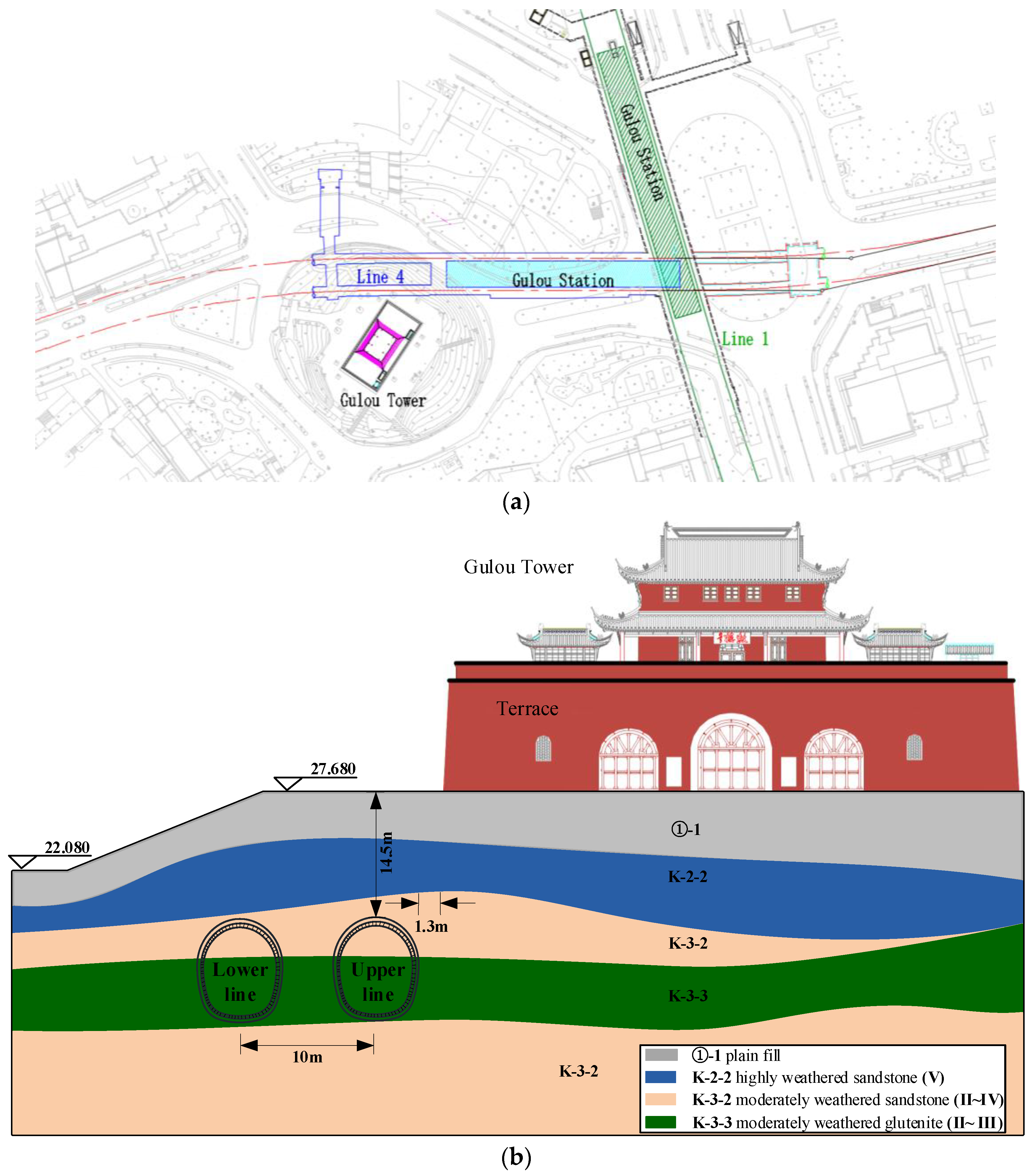
Figure 2, Gulou Tower is located near Gulou Station, as the transfer station of Metro Line 4. Tunnels are planned for development through the north corner of Gulou Tower, and the smallest distance between Gulou Tower and the upper line is only 1.3 m, as shown in
Figure 2a. Meanwhile, the historical building is also close to Gulou Station, with a distance of 7.3 m horizontally and 10.98 m vertically, and it has a triple-arch tunnel with a length of 38.95 m.
2.1. Structural Deterioration of Gulou Tower
Gulou Tower was built in 1382 in the Ming Dynasty and has a multi-story timber structure based on a masonry terrace made of rocks and bricks. With a height of 22.265 m, Gulou Tower was built for celebrations and time keeping with the beating of drums during the Ming Dynasty and the Qing Dynasty. The multi-story timber structure was destroyed around the year 1640 and then re-built in the year 1684 and underwent thorough maintenance in 1957. The masonry terrace has three arch passages, two chambers, and stairs leading to the top of the terrace with a height of 8.915 m. The timber-framed tower structure with a height of 13.315 m from the terrace top has two floors and a roof decorated with wood carvings, and the weight of the tower roof is sustained by wood pillars and masonry walls. There are 25 openings (1 for the front door and 24 for the windows) in the timber-framed building for sightseeing, suggesting that the building is vulnerable to disturbances and weathering in urban environments.
A detailed survey about the structural responses of the timber frame and the masonry terrace was implemented before the tunnel excavation.
- (a)
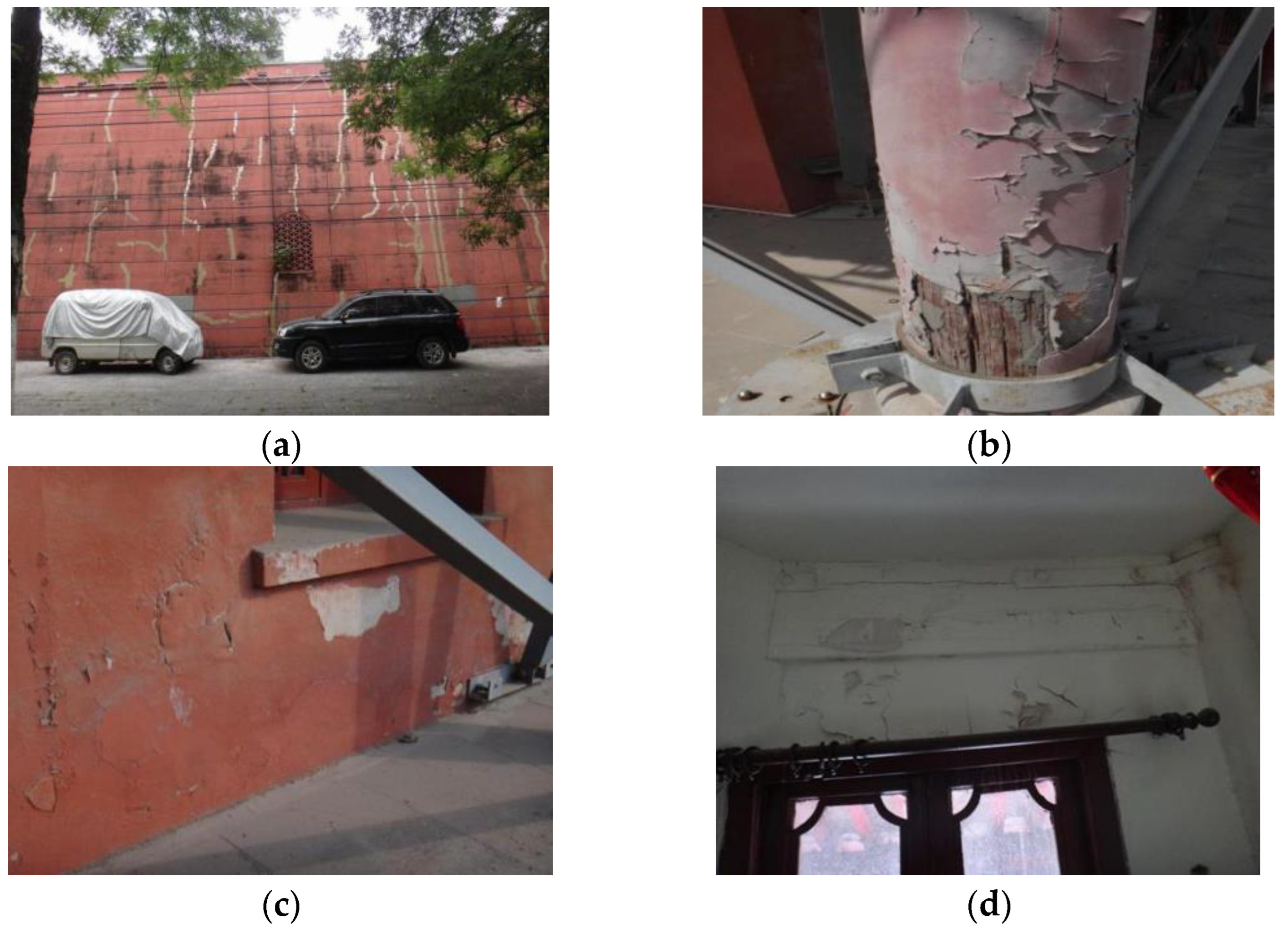
The masonry terrace. During the reparation in 1957, the arch passage was reinforced with 400 mm thick concrete. Due to the deterioration of the masonry wall, there existed a 180~355 mm inclination with a maximum inclination rate of 55.565‰. Vertical cracks could be found on the walls of the terrace with a maximum width of 3.0 mm (shown in
Figure 3a), and two cracks on the south elevation spread into the masonry, which broke the bricks.
- (b)
The timber-framed structure. There existed a maximum inclination rate of 13.48‰ for the eave columns and a deflection of 7.5~40.0 mm for the eave beams. The inclination of the walls of the timber-framed structure was 28~160 mm, with a maximum inclination rate of 22.9‰. Due to the aging of the timber-framed structure, cracks could be found on the exterior walls and wooden frames, including pillars and trusses and the roof, and the mortar cover on the walls and eave columns and beams had peeled off, as shown in
Figure 3.
From the survey results, it was found that the structural behaviors of the timber-framed structure have deteriorated due to roof leakage, cracking, the decaying of the wood frame, and vertical cracks on the masonry terrace. The results suggest that this building could be sensitive to the soil movement caused by tunnel excavation, and protection is essential for the safety of this structure.
2.2. Ground Conditions
Compared with the typical geological conditions in Nanjing characterized by the alluvial and silty floodplain of the Yangtze River, the soil profiles under Gulou Tower are quite different. The strata in this area consist of four main layers, as shown in
Figure 2b: plain fill, highly weathered sandstone, moderately weathered sandstone, and moderately weathered glutenite. The properties of these four layers are presented in
Table 2. Moreover, there exist boulders with diameters ranging from 0.2 m to 1.2 m in the weathered rocks. The ground conditions under Gulou Tower suggest that using an earth pressure balance (EPB) shield, which is used extensively in the construction of metro tunnels in Nanjing, is by no means an easy task. We discuss the tunneling methods in the next section.
3. Excavation and Construction of Tunnels and Gulou Station
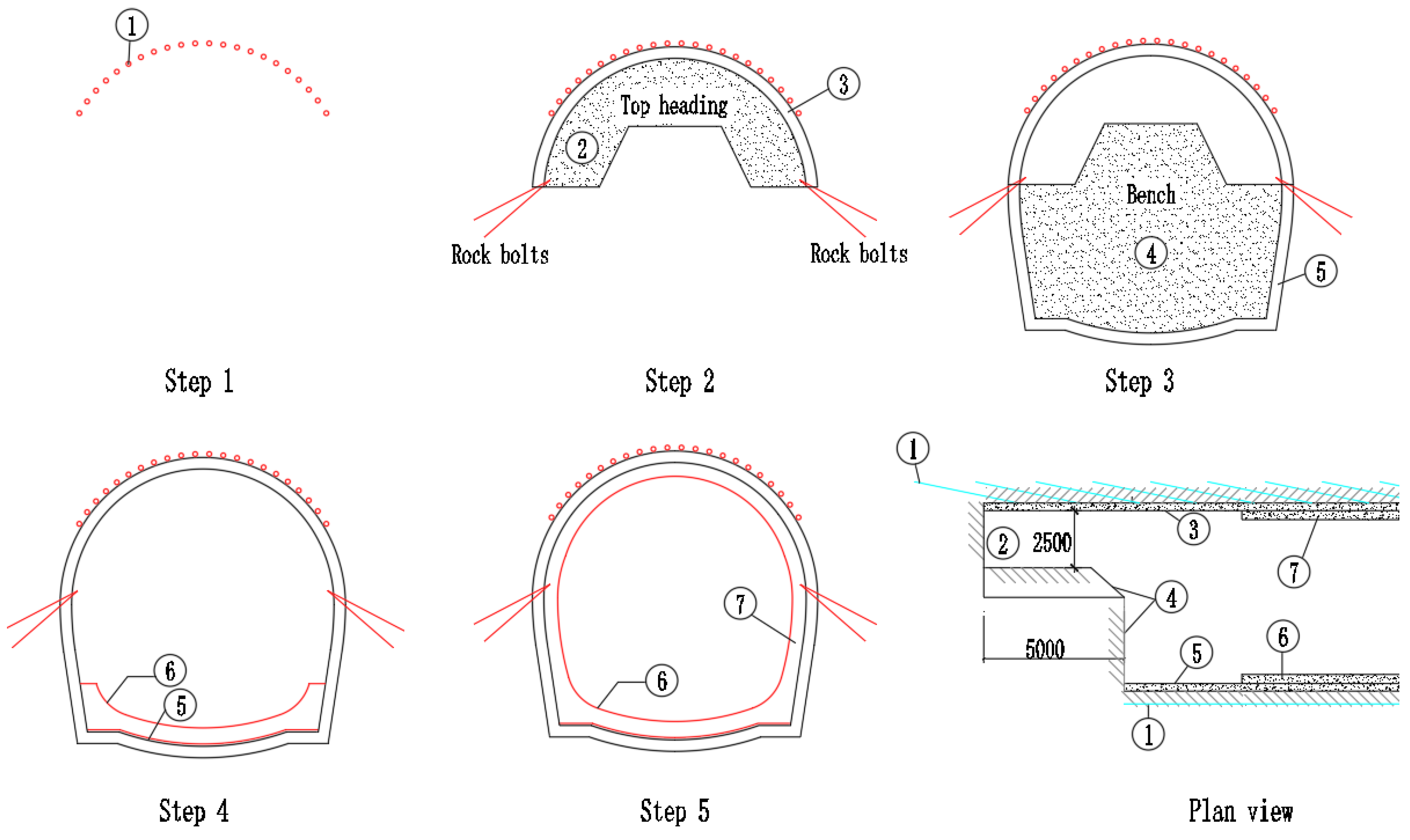
Due to the relatively small space between Gulou Tower, the tunnels, and Gulou Station, two issues are of great importance to mitigate the risk of structure cracks and differential settlement: (1) the excavation methods and construction procedures of the tunnels and Gulou station and (2) the reinforcements of Gulou Tower. Due to the ground conditions being unfavorable for the use of the earth pressure balance (EPB) method, the benching tunneling method was adopted to construct the twin tunnels and the triple-arch connection tunnel of Gulou Station. The detailed excavation procedures of the two tunnels are presented in
Figure 4.
Step 1: To improve ground stability, cement grout was injected into the rock mass via the boreholes drilled in the tunnel face. Step 2: The crown (Section ②) was excavated by using the milling excavation method to reduce the effect of the soil disturbance on Gulou Tower, and a temporary support of shotcrete was installed. The central part was kept during Step 2, with rock bolts (diameter = 30 mm and length = 3 m) installed at the bottom of the shotcrete to reinforce the stability of the excavation face. Step 3: The bench part (Section ④) was excavated after the installation of steel mesh around the freshly excavated face and protected by early-strength shotcrete with a 28-day characteristic compressive strength of 25 MPa. Step 4: Shotcrete was applied to the bottom of the tunnel, and a concrete lining ⑥ was installed. Step 5: An upper concrete lining ⑦ was installed to support the cavity.
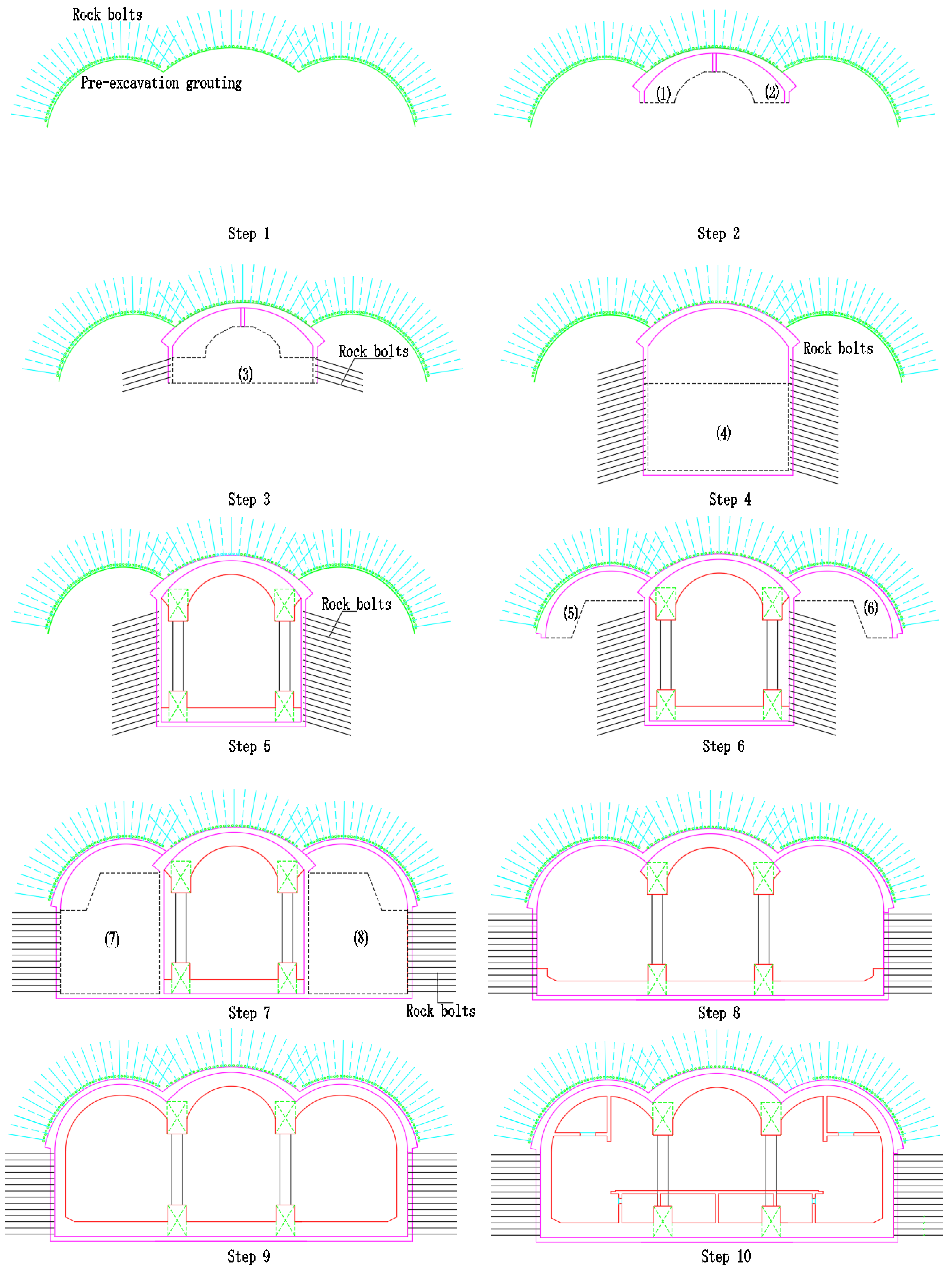
The construction procedures of the triple-arch tunnel (as the connection part of the two tunnels and Gulou Station) are shown in
Figure 5. Pre-excavation grout was firstly injected into the rock mass, and rock bolts were installed to provide the initial support for the tunnel excavation. The top heading parts (1) and (2) of the middle tunnel were excavated in Step 2, and concrete lining was installed in the ceiling of the tunnel to support the excavated face. Then, bench parts (3) and (4) were excavated, and rock bolts and columns were installed to support the middle tunnel during Step 3, Step 4 and Step 5. After that, the top heading parts (5) and (6) of the side tunnels were excavated, and the corresponding top linings were installed in Step 6. Bench parts (7) and (8) were then excavated, and rock bolts were installed to support the sidewalls of the side tunnels in Step 7. After that, the inverts of the side tunnels were constructed in Step 8, and the final concrete linings were casted in place in Step 9 and Step 10.
4. Instrumentation and Measurement
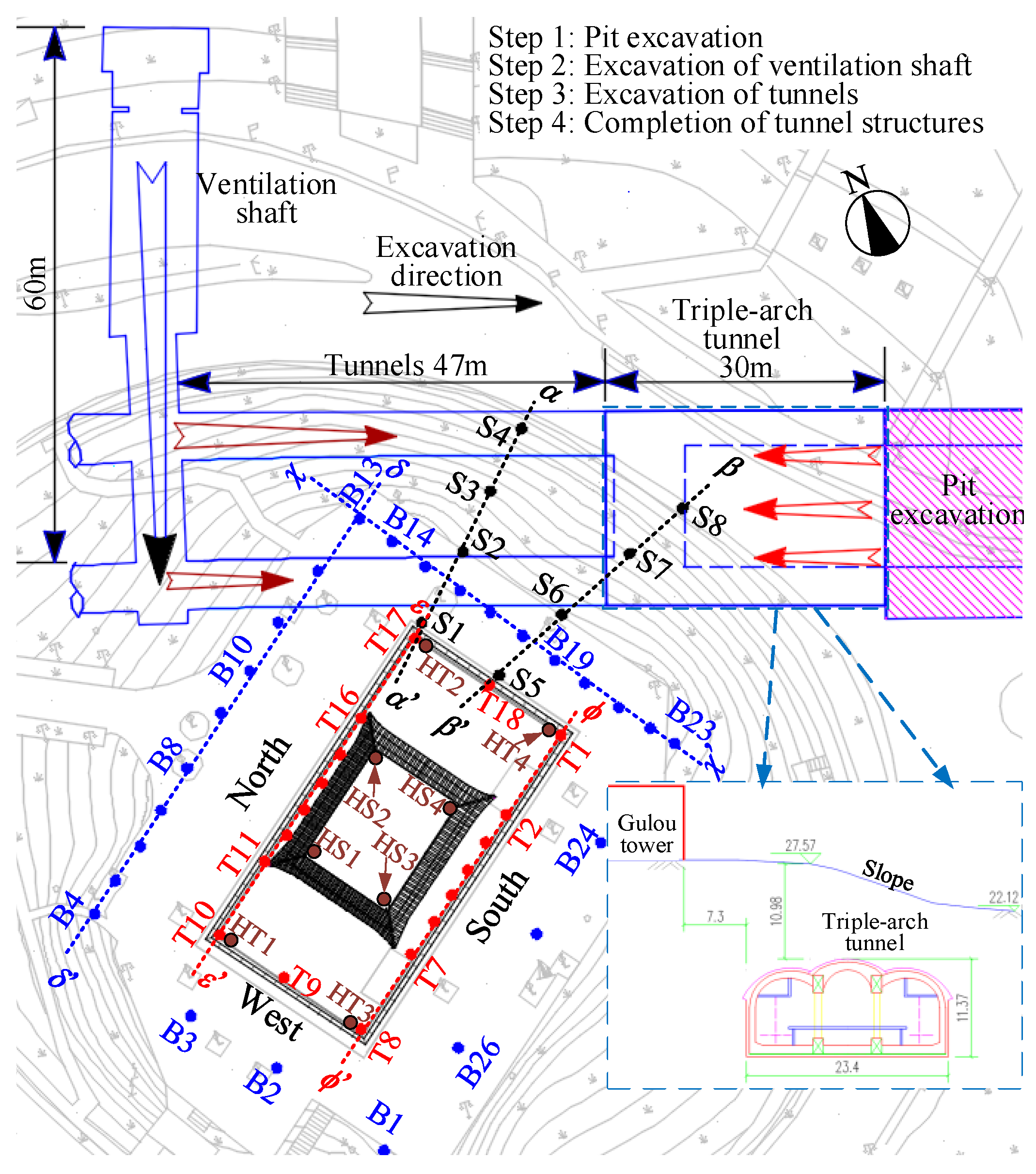
Figure 6 illustrates the construction procedures of the whole project and the monitoring points of the ground surface and Gulou Tower. The arrows represent the excavation directions of the ventilation shaft, the two tunnels, and the triple-arch tunnel, and the four-phase construction procedures are summarized in
Chart 1. We also labeled five time nodes on the flowchart, including ① the end of the pit excavation of Gulou Station; ② the end of the excavation of the ventilator shaft; ③ the start of the excavation of the triple-arch tunnel; ④ the end of the triple-arch tunnel excavation; and ⑤ the end of the whole project.
Phase 1: From August to December 2013, a foundation pit in Gulou Station of Metro Line 4 was excavated in the northeast corner of Gulou Tower.
Phase 2: The excavation of a ventilation shaft in Gulou Station from north to south began on 21 December 2013 and finished in July 2014. Then, the whole project was suspended due to the Nanjing Youth Olympic Games.
Phase 3: The triple-arch station and the 47 m long tunnels were excavated again from 1 September 2014 to 13 February 2015. The two tunnels were excavated after the completion of the triple-arch tunnel excavation. The steel pipe installation and the pre-excavation grouting were carried out at the excavation face by using the construction space created by the ventilation shaft. After advancing the excavation face of the lower line by 20 m, the excavation of the upper line began and maintained the excavation pace of the lower line.
Phase 4: On 10 June 2015, the construction of the main structure was completed.
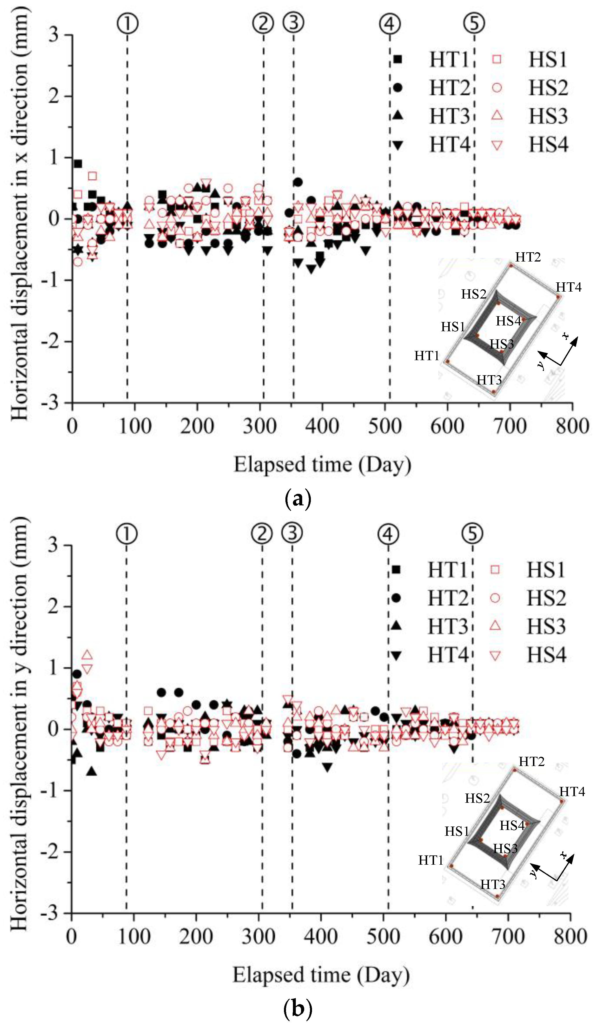
During the tunnel excavation and station construction, the ground settlements were monitored at thirty-four monitoring points (B1 to B26, S1 to S4, and S5 to S8). Meanwhile, the displacement responses of the historic building were also monitored, including 18 monitoring points for the vertical displacements (from T1 to T18) and 8 points for the horizontal displacements (HT1 to HT4 for the terrace and HS1 to HS4 for the timber-framed structure).
5. Reinforcements of Gulou Tower
Considering the potential threats to Gulou Tower due to the ground movement, the terrace and the timber-framed structure were reinforced before the tunnel excavation.
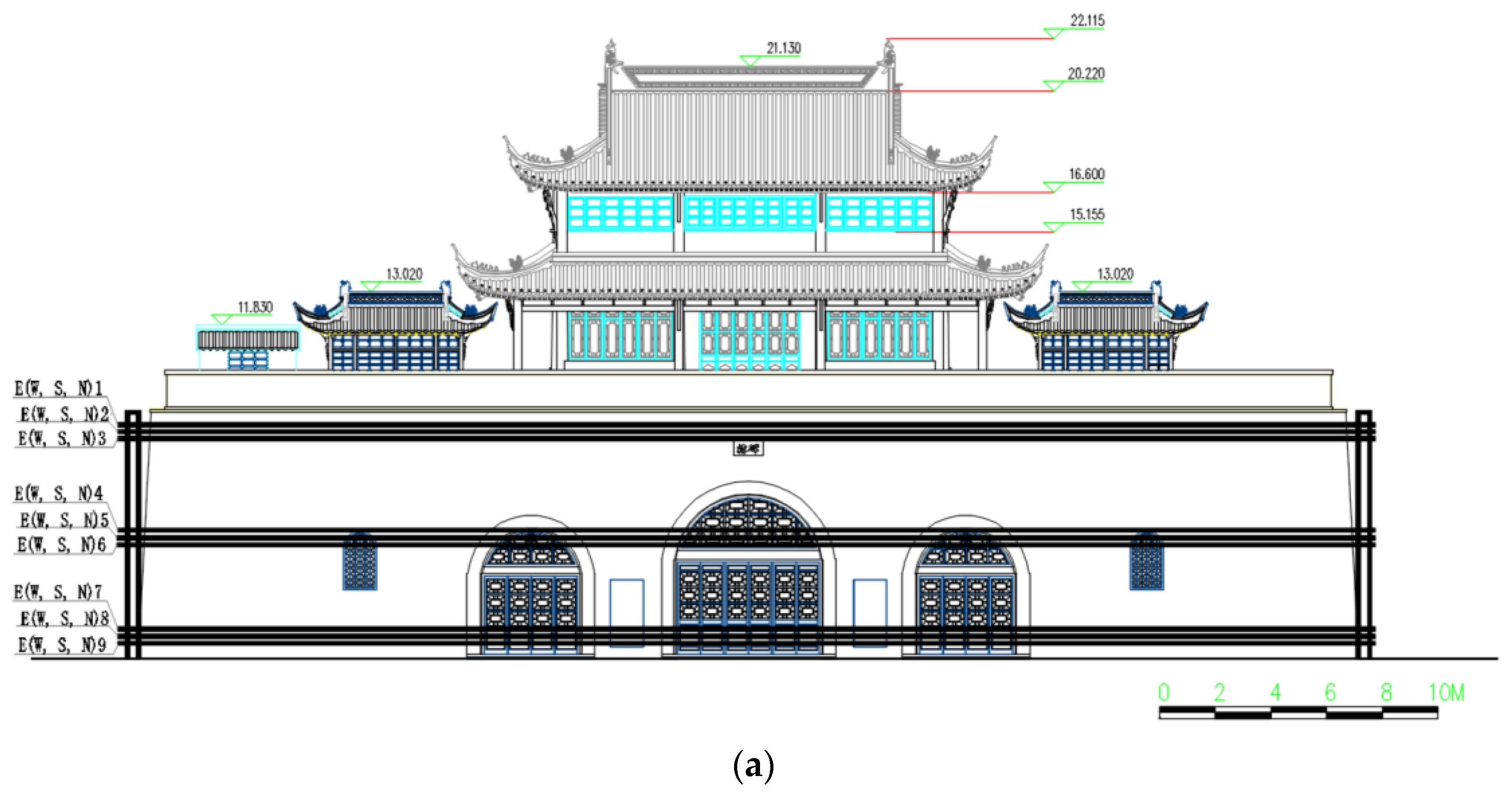
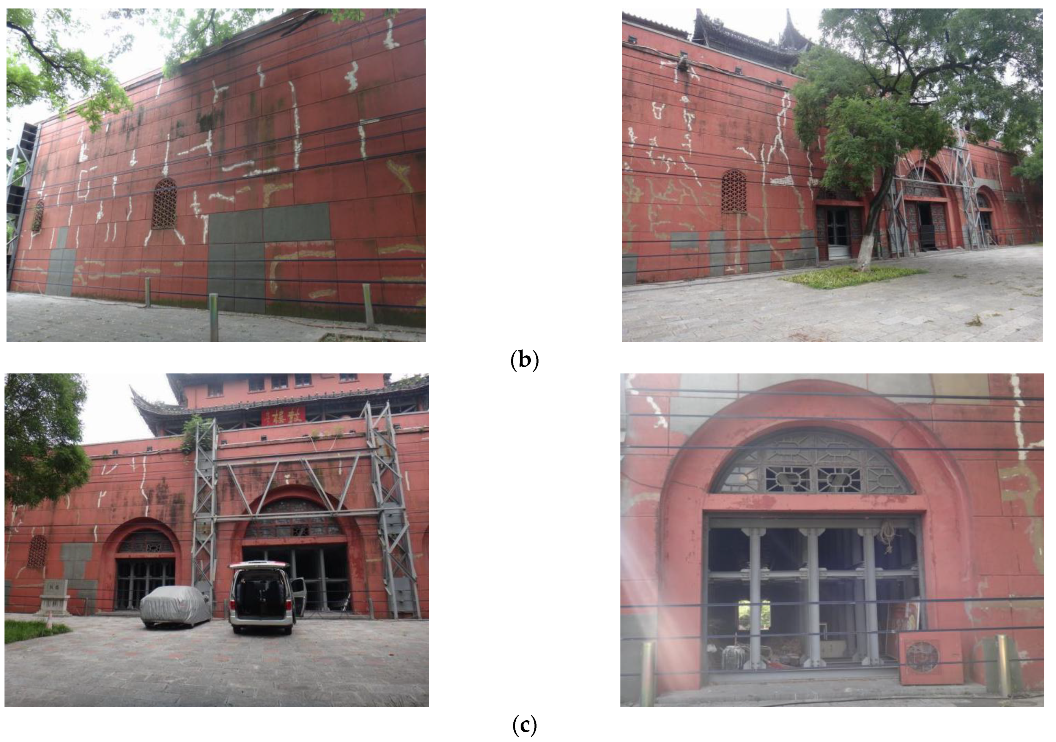
(i) The terrace. Steel columns were installed at the four corners of the terrace and were anchored with nine bundles of pre-stressed steel wires, as shown in
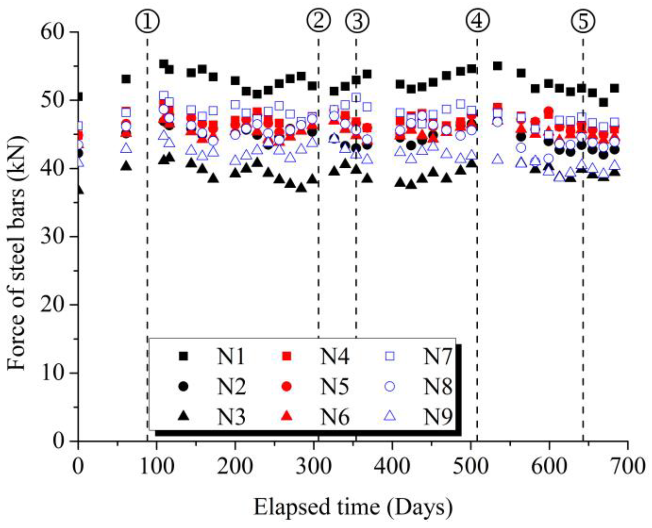
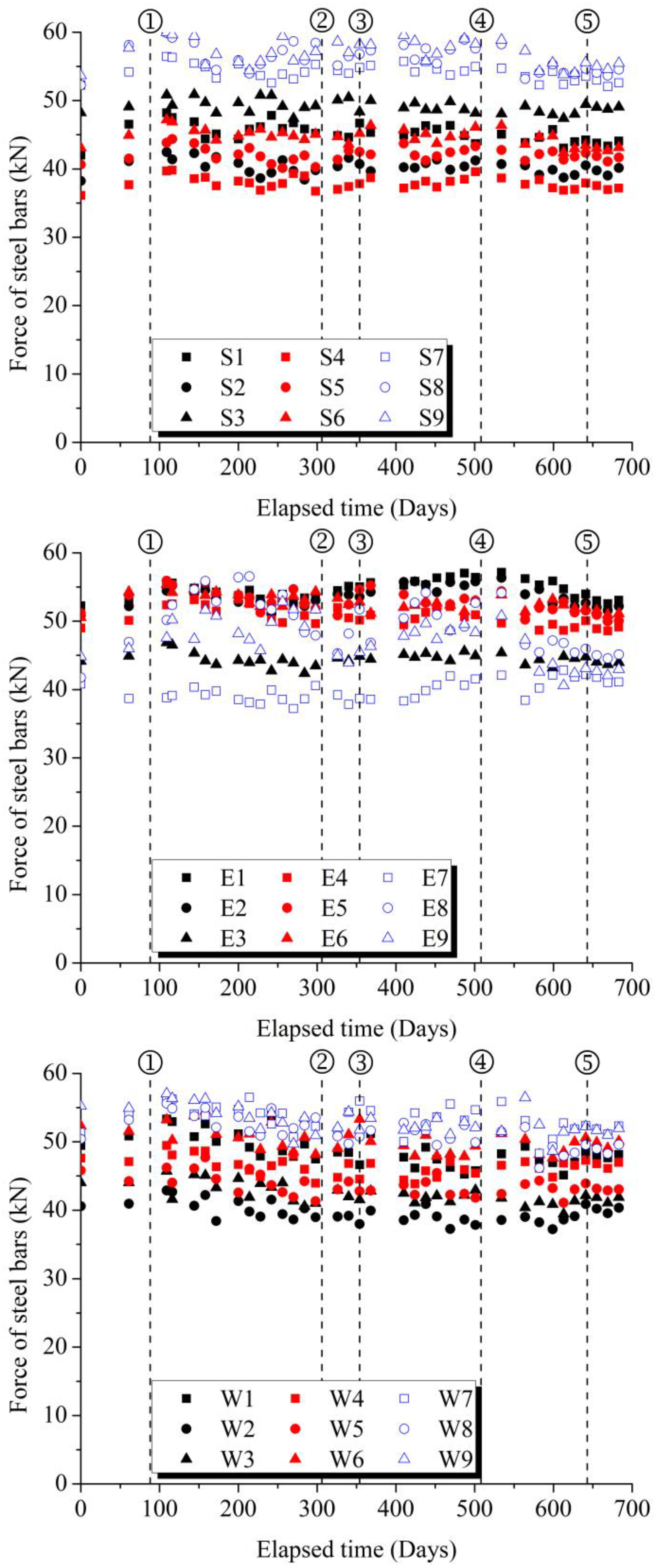
Figure 7. Each bundle of steel wires consisted of seven steel strands of American ASTMA416-92 standard with a diameter of Φ5 and a standard strength of 1860 MPa. Then, 6 cm thick rubber isolators were placed between the steel columns and the terrace to avoid direct contact, which could damage the bricks. With the initial pre-stress ranging from 45 kN to 50 kN, the stress variations of the steel wires during the tunnel excavation are presented in
Figure 8, with E, W, S, and N standing for the four elevations of the terrace. We could observe an increase in the tensile stress during the tunnel excavation between time nodes ③ and ④, especially for the steel bars at the north elevation and the east elevation, which are close to the tunnel excavation. After the tunnel excavation (from time node ④ to ⑤), the tensile stresses of the steel wires in the four elevations gradually reduced to the initial pre-stresses. Meanwhile, the passenger tunnel of the terrace was reinforced by a steel frame, as shown in
Figure 7c, which was similar to the protection provided for the Ming Dynasty city wall during the development of the Xi’an Metro Line crossing underneath perpendicularly (Lai et al., 2020 [
23]).
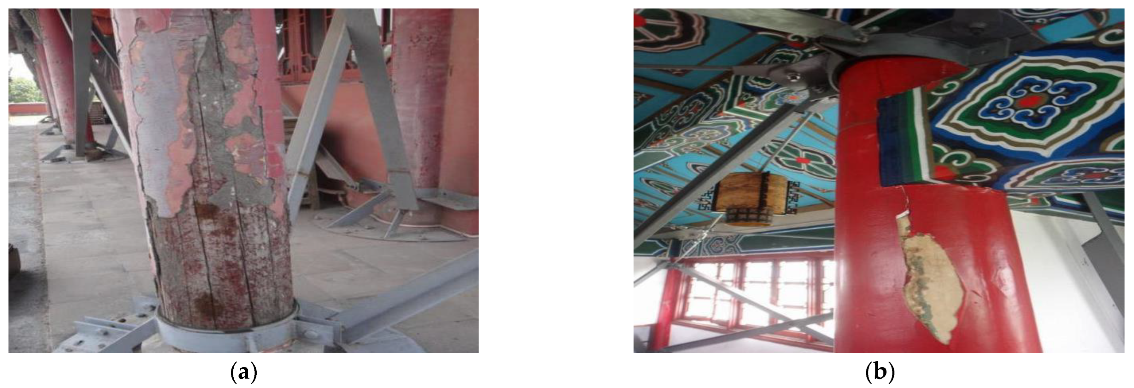
(ii) The timber-framed structure. To avoid further damage caused by the differential settlement to the timber-framed building, each wood column was reinforced with the steel boot shown in
Figure 9a anchored on the floor before the tunnel excavation. Meanwhile, vertical, horizontal, and crossing trusses were installed to improve the overall stiffness of the building, as shown in
Figure 9b. The wooden beam–column joints were reinforced by steel connectors, and rubber pads were used to avoid the stress concentration caused by the steel connectors on the wooden structures.
6. Measured Ground Settlements during Tunnel Excavation
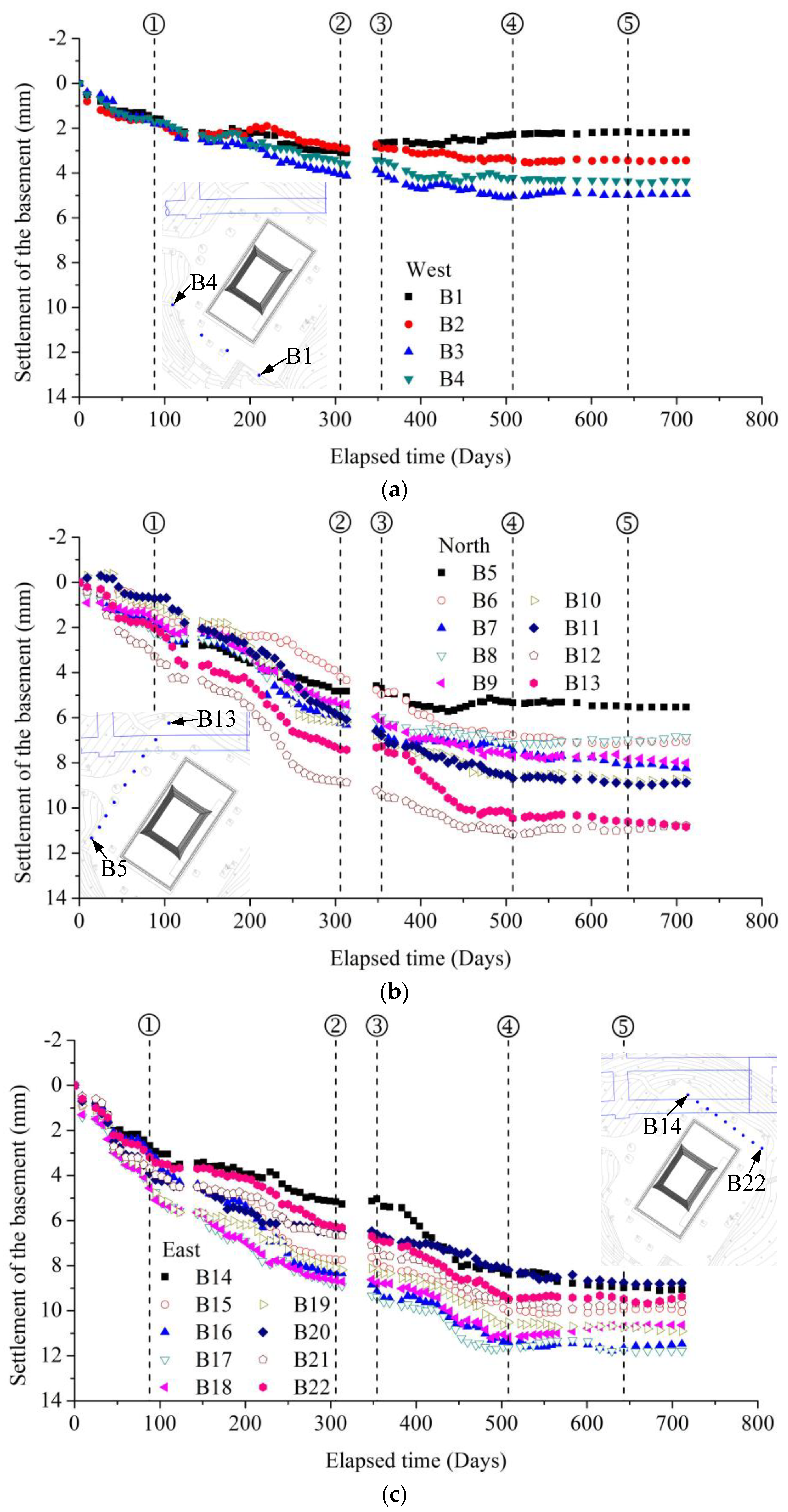
In this section, the tunneling-induced ground settlements were continuously monitored at points B1~B26 around Gulou Tower, as shown in
Figure 10, and at points S1~S8 between the historic building relative to the metro tunnels and Gulou Station, as shown in
Figure 11, with the elapsed time from 22 September 2013 to 1 September 2015. Meanwhile, we further present the settlement curves along Line
χχ′ and Line
δδ′ in
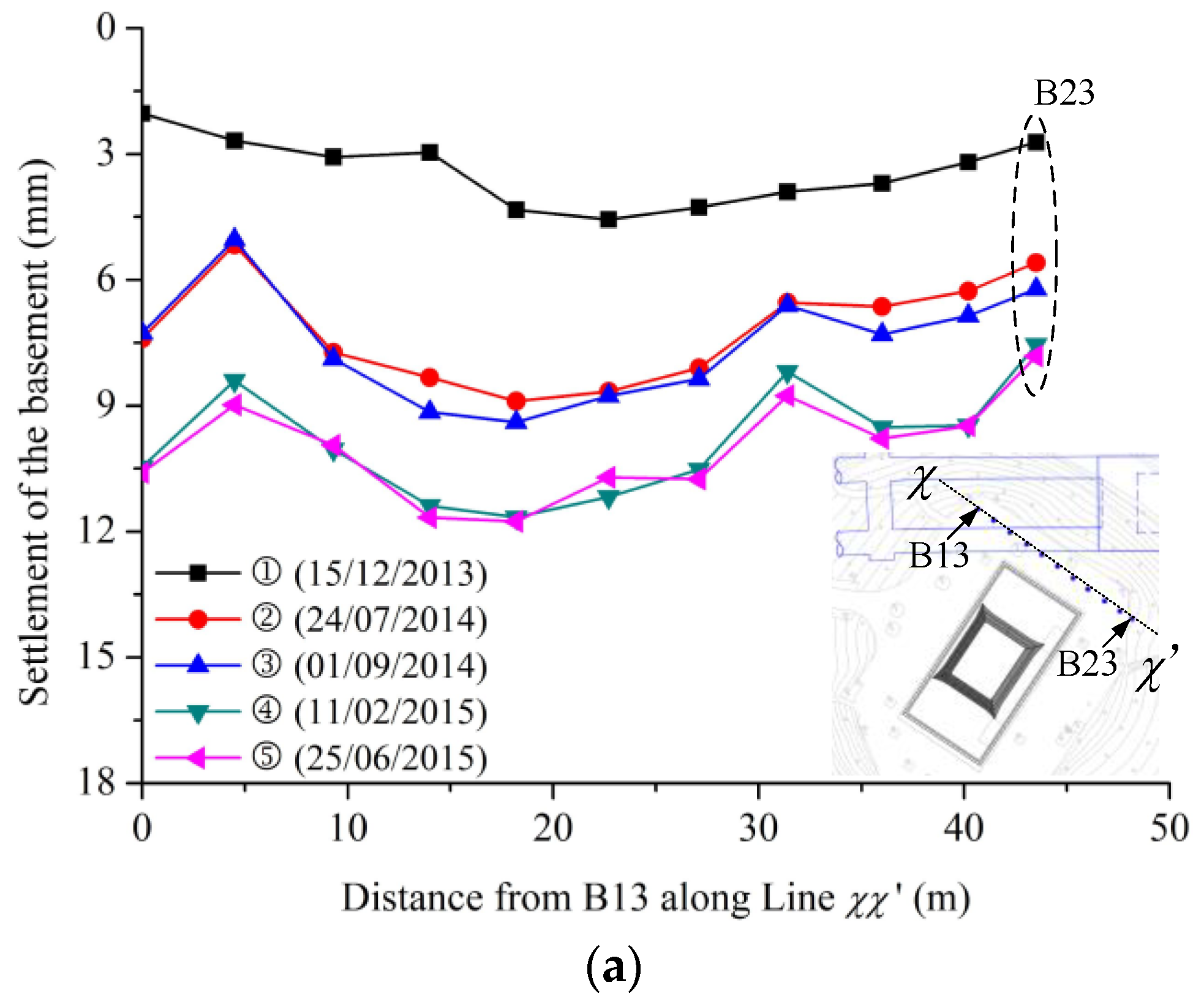
Figure 12. Considering the multi-step construction and the oblique crossing between the tunnels and Gulou Tower, we focused on two key factors of the surface settlements:
- (1)
The proportion of the settlements at different construction steps. As can be seen from the monitored results, the ground settlement was caused by three reasons: the pit excavation of the station (time node ①), the excavation of the ventilation shaft (from time node ① to time node ②), and the tunnel excavation (from time node ③ to time node ④). The maximum final settlement around Gulou Tower occurred at monitoring point B17 with a value of 11.79 mm, which was less than the allowable ground settlement of 15 mm. However, the ground settlement was mainly caused by the excavation of the pit foundation and the ventilation shaft in this case. The ratio of the settlement at time node ② over the final settlement, S②/Sfinal, was greater than 0.7 for the monitoring points. Such results indicate that, for the protection of the masonry building near the subway station, attention should be paid not only to the influence of tunneling but also to the influence of the construction of the station and accessory structures, such as the ventilation shaft in this case.
- (2)
Relative position between monitoring points and construction sites. Surface settlements due to soil disturbance were highly related to the distance between the monitoring points and the construction sites of the pit foundation, ventilation shaft, and tunnels. For example, the settlements at the points from B14 to B24 in
Figure 10, together with S4 and S8 in
Figure 11, increased rapidly at time node ① since these points were closer to the pit excavation. The excavation of the ventilation shaft resulted in a greater settlement increase at the monitoring points from B5 to B13 in
Figure 10b between time nodes ① and ②, while the tunnel excavation had a more significant influence on the monitoring points from B11 to B18. However, the settlements of the monitoring points from B1 to B4 and B26 were smaller since these points were relatively far away from the construction sites, which is shown by the settlement distribution along Line
χχ′ and Line
δδ′ in
Figure 12.
7. Structure Responses during Tunneling
As can be seen in
Section 5, the ground settlement surrounding Gulou Tower was highly affected by the excavation procedures and the relative position between the building and tunnels. Considering the differential settlement and the deteriorated structural behaviors, some protection measures were proposed to improve the structure behaviors, including steel columns and steel wires for anchoring the terrace, a steel frame for supporting the passenger tunnel, and a steel framework for reinforcing the timber structure. This section presents the settlement behaviors of Gulou Tower in
Figure 13 and
Figure 14 and the horizontal displacement in
Figure 15 under such protection measures.
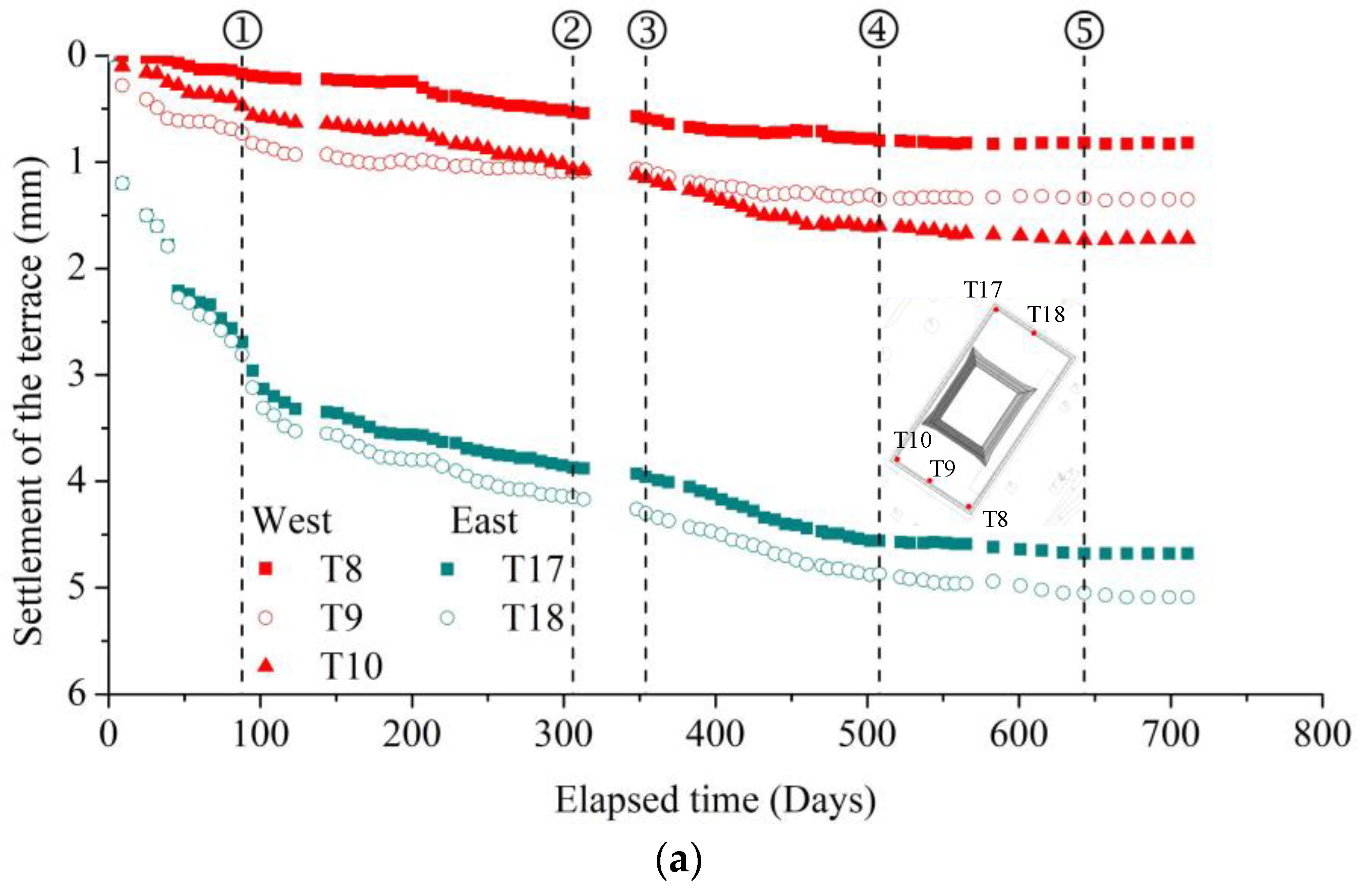
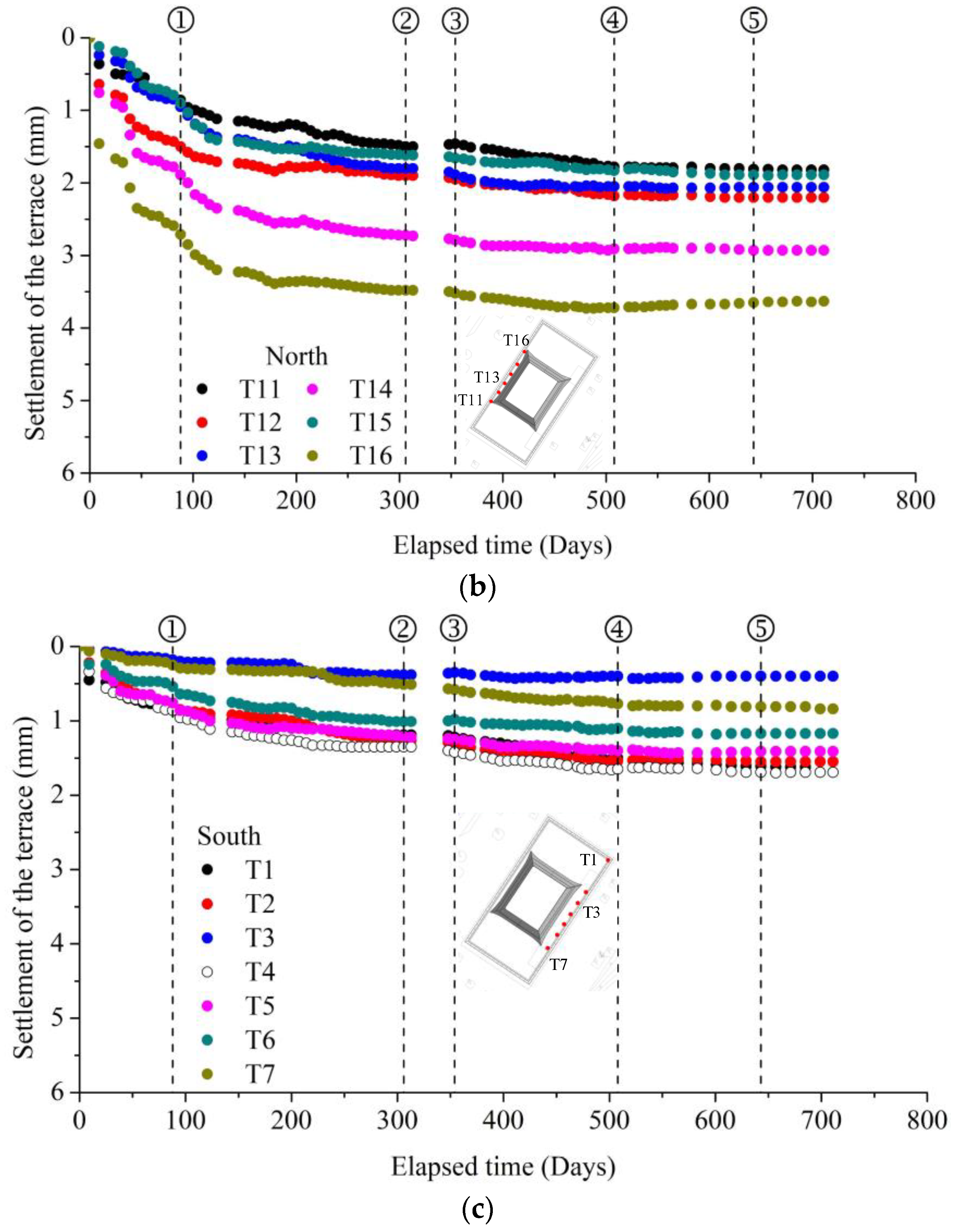
Figure 13 shows the settlement development of the monitoring points (from T1 to T18) at the terrace of Gulou Tower. Due to the oblique crossing between the tunnels and the historical building, the terrace settled differentially, with the settlements at the east elevation being higher than those at the west elevation. The northeast corner of the terrace (T16, T17, and T18) suffered from a higher settlement mainly due to the relatively small distance from the excavation sites. After the excavation of the adjacent pit and the construction of the ventilation shaft, the settlement of the points close to the tunnels, such as T17 and T18, were higher than 4 mm at time node ②, which was close to the limit of the allowable settlement of 5 mm. Such a rapid increase in settlement posed a threat to the safety of the historical building. Therefore, during the following excavation of the tunnels, pre-excavation grouting and steel pipe installation were carried out to reduce the soil disturbance. With these protection measures, the maximum settlement of the historical building was 5.12 mm, recorded at point T18, which was slightly higher than the allowable settlement (5 mm).
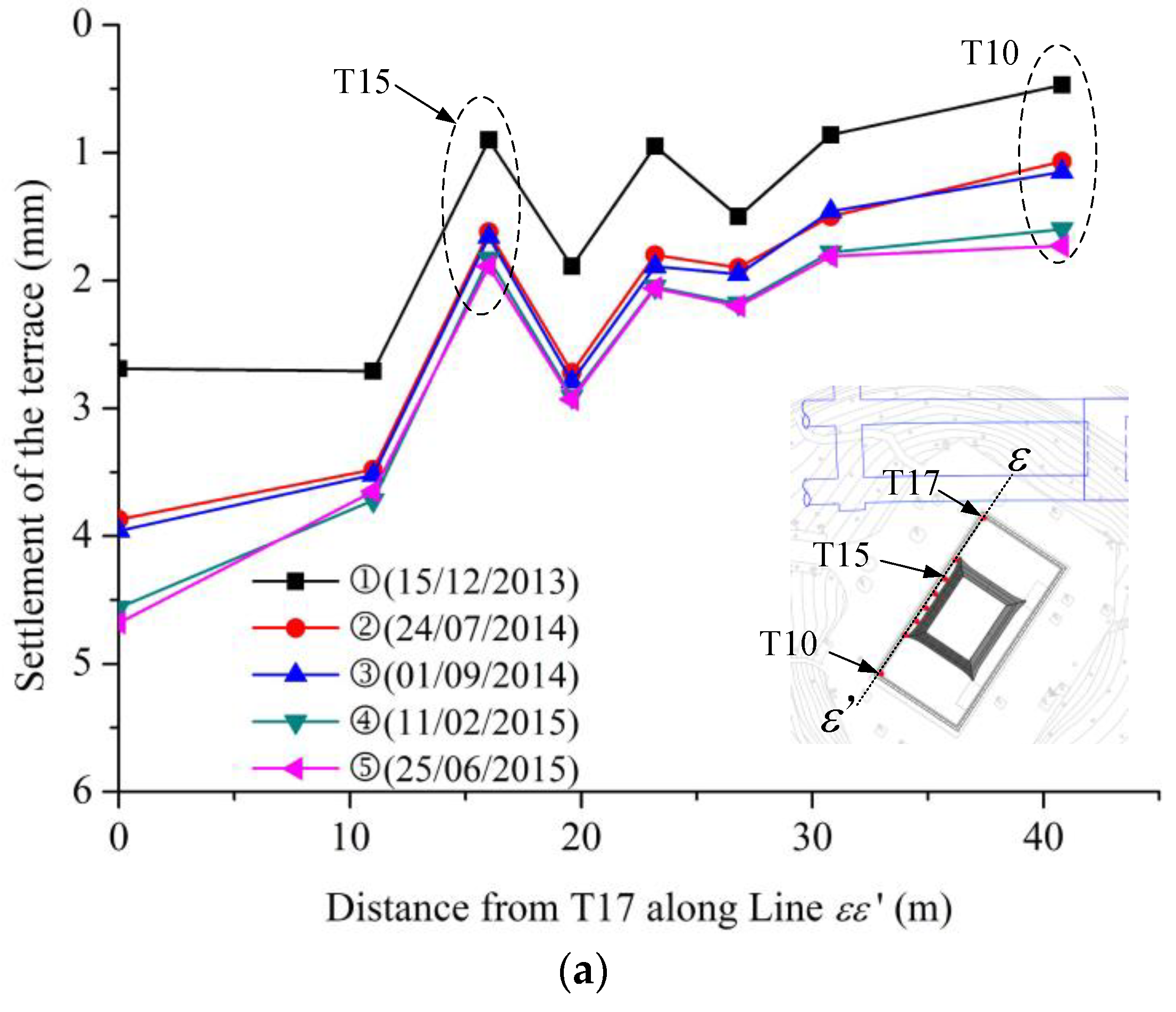
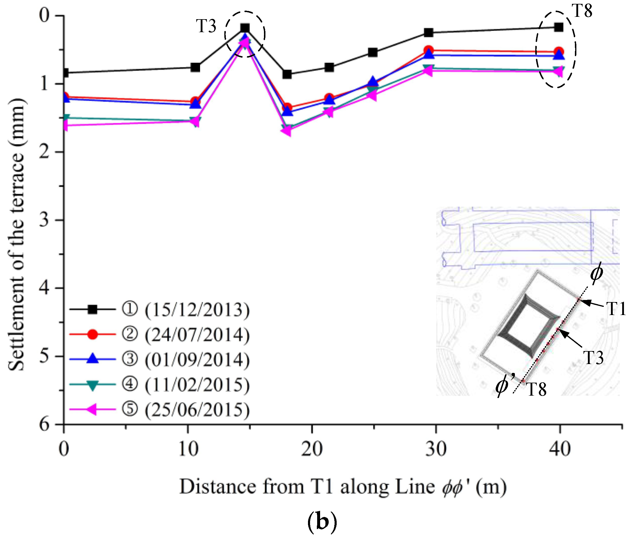
We also presented the settlement along Line
εε′ and along Line
ϕϕ′ at different time nodes, as shown in
Figure 14a,b, respectively. Since the northeast corner of the historical building is close to the tunnels, we observed that the settlement of T17 was higher than that of T10 and T8 at the west elevation during the construction. A significant reduction in the terrace settlement at T15 and T3, which coincided with the placement of the steel frames for the passenger tunnels, could be found compared with that at the adjacent monitoring points. This implies that the steel frame under the passenger tunnels provided extra vertical support, which improved the overall stiffness of the terrace. Meanwhile, the horizontal displacements of the terrace (HT) and the timber-framed structure (HS) in the
x and
y directions during the project are presented in
Figure 15. With the pre-stressed steel wire anchoring the terrace, the horizontal displacements of Gulou Tower were small during the tunnel excavation and the station construction.
8. Conclusions
In this research, we present the protection measurements and the displacement response of a hybrid timber–masonry historical building near a tunnel excavation in Nanjing, China. Due to the relatively small spacing between Gulou Tower and the metro tunnel, as well as the deteriorated structure behaviors, two key aspects were emphasized during the construction procedures: (i) how to reduce the soil movement considering the ground conditions and (ii) how to increase the total stiffness of the historical building. Extensive field monitoring data were interpreted and discussed, and the following conclusions were drawn:
- (1)
Due to the unfavorable conditions for the earth pressure balance (EPB) method, the benching tunneling method was used in this case. The excavation procedures of the tunnels were carefully selected, and a pre-excavation grout injection and the installation of steel pipes were used to reduce soil movement. The maximum ground settlement was 11.79 mm at monitoring point B17, less than the allowable ground settlement of 15 mm, suggesting that these engineering measures were adequate to control the soil disturbance during tunneling.
- (2)
To improve the stiffness of Gulou Tower, pre-stressed steel wire anchoring the terrace, steel frames supporting the passenger tunnel, and steel frameworks reinforcing the timber structure were implemented. The maximum settlement was recorded in the middle of the east elevation of Gulou Tower (T18), which was close to the excavation of the two tunnels and the triple-arch tunnel. Although the historical building sustained differential settlements caused by the tunnels passing through the north corner of Gulou Tower, the displacements of Gulou Tower were kept within acceptable values. Due to the extra support provided by the steel frames under the passenger tunnel, the vertical displacements of the terrace were significantly reduced. Meanwhile, the horizontal displacements were small, mainly due to the pre-stressed steel wire anchoring the terrace.
- (3)
Although the displacements of Gulou Tower were limited to the acceptable values, the settlement development of Gulou Tower was significantly affected by the construction procedure. Over 70% of the settlement of Gulou Tower was caused by the pit excavation of Gulou Station and the excavation of the ventilation shaft, and the settlement development of the monitoring points was significantly affected by the relative position between Gulou Tower and the construction sites. This suggests that, for historical buildings adjacent to metro stations, attention should be paid not only to the tunnel excavation but also to the construction of the station and the appurtenance.
Due to the 3D nature and complexity of the case studied, advanced data digging technology is called for to further identify the key factors determining the excavation-induced displacement of hybrid timber–masonry historical structures, e.g., the ANN Deep Learning Auto-Encoder [
28,
29]. Furthermore, it is essential to perform further 3D numerical analyses to accurately describe the ground settlement and the relevant displacement response of historical structures during metro tunnel excavation.
Author Contributions
Conceptualization, S.G. and K.Z.; Methodology, S.G., J.J., Z.L. and K.Z.; Validation, H.Z., B.L. and K.Z.; Formal analysis, Y.R.; Investigation, Y.R.; Resources, B.L. and Z.L.; Data curation, H.Z.; Writing—original draft, H.Z.; Writing—review & editing, S.G. and J.J.; Project administration, B.L. All authors have read and agreed to the published version of the manuscript.
Funding
This research was funded by the Scientific Research Fund of Institute of Engineering Mechanics, China Earthquake Administration [grant number: 2019D05], and the National Natural Science Fund of China [grant number: 51978335, 52168044, 51668002].
Data Availability Statement
Data sharing not applicable.
Acknowledgments
The authors are grateful to the High Performance Computing Center of Nanjing Tech University for providing the computational resources.
Conflicts of Interest
The authors declare no conflict of interest.
References
- Amorosi, A.; Bolding, D.; De Felice, G.; Malena, M.; Sebastianelli, M. Tunnelling-induced deformation and damage on historical masonry structures. Géotechnique 2014, 64, 118–130. [Google Scholar] [CrossRef]
- Ledesma, A.; Alonso, E.E. Protecting sensitive constructions from tunnelling: The case of World Heritage buildings in Barcelona. Géotechnique 2017, 67, 914–925. [Google Scholar] [CrossRef]
- Giardina, G.; Hendriks, M.A.N.; Rots, J.G. Damage functions for the vulnerability assessment of masonry buildings subjected to tunneling. J. Struct. Eng. 2015, 141, 04014212. [Google Scholar] [CrossRef]
- Hussain, E.M.A.; Zhang, S.; Moawwez, M.A.; Umar, T.; Iqbal, M.R.; Kamran, M.; Muneer, M. A Review of Spatial Variations of Multiple Natural Hazards and Risk Management Strategies in Pakistan. Water 2023, 15, 407. [Google Scholar] [CrossRef]
- Zhao, K.; Janutolo, M.; Barla, G. A completely 3D model for simulation of mechanised tunnel excavation. Rock Mech. Rock Eng. 2012, 45, 475–497. [Google Scholar] [CrossRef]
- Giardina, G.; DeJong, M.J.; Mair, R.J. Interaction between surface structures and tunnelling in sand: Centrifuge and computational modelling. Tunn. Undergr. Space Technol. 2015, 50, 465–478. [Google Scholar] [CrossRef]
- Bilotta, E.; Paolillo, A.; Russo, G.; Aversa, S. Displacements induced by tunnelling under a historical buildings. Tunn. Undergr. Space Technol. 2017, 61, 221–232. [Google Scholar] [CrossRef]
- Dalgic, K.D.; Hendriks, M.A.N.; Ilki, A. Building response to tunnelling- and excavation-induced ground movements: Using transfer functions to review the limiting tensile strain method. Struct. Infrastruct. Eng. 2018, 14, 766–779. [Google Scholar] [CrossRef]
- Zhao, K.; Janutolo, M.; Barla, G.; Chen, G.X. 3D simulation of TBM excavation in brittle rock associated with fault zones: The Brenner Exploratory Tunnel case. Eng. Geol. 2014, 181, 93–111. [Google Scholar] [CrossRef]
- Dalgic, K.D.; Hendriks, M.A.N.; Ilki, A.; Broere, W. A two-stage numerical analysis approach for the assessment of the settlement response of the pre-damaged historic Hoca Pasha Mosque. Int. J. Archit. Herit. 2019, 13, 704–724. [Google Scholar] [CrossRef]
- Giardina, G.; Marini, A.; Riva, P.; Giuriani, E. Analysis of a scaled stone masonry façade subjected to differential settlements. Int. J. Archit. Herit. 2019, 14, 1502–1516. [Google Scholar] [CrossRef]
- Bejarano-Urrego, L.; Verstrynge, E.; Giardina, G.; Balen, K.V. Crack growth in masonry: Numerical analysis and sensitivity study for discrete and smeared crack modelling. Eng. Struct. 2018, 165, 471–485. [Google Scholar] [CrossRef]
- Elakayam, I.; Klar, A. Nonlinear elastoplastic formulation for tunneling effects on superstructures. Can. Geotech. J. 2019, 56, 959–969. [Google Scholar] [CrossRef]
- Franzar, A.; Marshall, A.M. Centrifuge and real-time hybrid testing of tunneling beneath piles and piled buildings. J. Geotech. Geoenviron. Eng. 2019, 145, 04018110. [Google Scholar] [CrossRef]
- Lu, H.; Shi, J.; Ng, C.W.W.; Lv, Y. Three-dimensional centrifuge modeling of the influence of side-by-side twin tunneling on piled raft. Tunn. Undergr. Space Technol. 2020, 103, 103486. [Google Scholar] [CrossRef]
- Soomro, M.A. 3D finite element analysis of effects of twin stacked tunnels at different depths and with different construction sequence on a piled raft. Tunn. Undergr. Space Technol. 2021, 109, 103759. [Google Scholar] [CrossRef]
- Zhao, K.; Bonini, M.; Debernardi, D.; Janutolo, M.; Barla, G.; Chen, G.X. Computational modelling of the mechanized excavation of deep tunnels in weak rock. Comput. Geotech. 2015, 66, 158–171. [Google Scholar] [CrossRef]
- Collepardi, M. Thaumasite formation and deterioration in historic buildings. Cem. Concr. Comp. 1999, 21, 147–154. [Google Scholar] [CrossRef]
- Böke, H.; Akkurt, S. Ettringite formation in historic bath brick-lime plasters. Cem. Concr. Res. 2003, 33, 1457–1464. [Google Scholar] [CrossRef]
- Rahman, M.M.; Bassuoni, M.T. Thaumasite sulfate attack on concrete: Mechanisms, influential factors and mitigation. Constr. Build. Mater. 2014, 73, 652–662. [Google Scholar] [CrossRef]
- Saheb, M.; Chabas, A.; Mertz, J.; Colas, E.; Rozenbaum, O.; Sizun, J.; Nowak, S.; Gentaz, L.; Verney-Carron, A. Weathering of limestone after several decades in an urban environment. Corros. Sci. 2016, 111, 742–752. [Google Scholar] [CrossRef]
- Gong, C.J.; Ding, W.Q.; Xie, D.W. Twin EPB tunneling-induced deformation and assessment of a historical masonry building on Shanghai soft clay. Tunn. Undergr. Space Technol. 2020, 98, 103300. [Google Scholar] [CrossRef]
- Lai, J.X.; Zhou, H.; Wang, K.; Qiu, J.L.; Wang, L.X.; Wang, J.B.; Feng, Z.H. Shield-driven induced ground surface and Ming Dynasty city wall settlement of Xi’an metro. Tunn. Undergr. Space Technol. 2020, 97, 103220. [Google Scholar] [CrossRef]
- Miliziano, S.; de Lillis, A. Predicted and observed settlements induced by the mechanized tunnel excavation of metro line C near S. Giovanni station in Rome. Tunn. Undergr. Space Technol. 2019, 86, 236–246. [Google Scholar] [CrossRef]
- Bilotta, E. Use of diaphragm walls to mitigate ground movements induced by tunnelling. Géotechnique 2008, 58, 143–155. [Google Scholar] [CrossRef]
- Bilotta, E.; Russo, G. Use of a line of piles to prevent damages induced by tunnel excavation. J. Geotech. Geoenviron. Engng. 2011, 137, 254–262. [Google Scholar] [CrossRef]
- Bilotta, E.; Stallebrass, S.E. Prediction of stresses and strains around model tunnels with adjacent embedded walls in overconsolidated clay. Comput. Geotech. 2009, 36, 1049–1057. [Google Scholar] [CrossRef]
- Umar, T. Key factors influencing the implementation of three-dimensional printing in construction. Manag. Procure. Law 2020, 174, 104–117. [Google Scholar] [CrossRef]
- Umar, T.; Salih, R.; Akbar, M.; Hussain, Z. Structural Health Monitoring of Underground Metro Tunnel by Identifying Damage Using ANN Deep Learning Auto-Encoder. Appl. Sci. 2023, 13, 1332. [Google Scholar]
Figure 1.
Sectional view of hybrid timber–masonry historical structures. (a) South elevation. (b) North elevation. (c) East elevation. (d) West elevation. (e) Perspective drawing of the masonry terrace.
Figure 1.
Sectional view of hybrid timber–masonry historical structures. (a) South elevation. (b) North elevation. (c) East elevation. (d) West elevation. (e) Perspective drawing of the masonry terrace.
Figure 2.
Location of Gulou Tower along Metro Line 4 in Nanjing, China. (a) Plan view of the tunnels and Gulou Tower. (b) Sectional view of the tunnels and Gulou Tower.
Figure 2.
Location of Gulou Tower along Metro Line 4 in Nanjing, China. (a) Plan view of the tunnels and Gulou Tower. (b) Sectional view of the tunnels and Gulou Tower.
Figure 3.
Deterioration of the timber structure, including pillars, walls, and joints. (a) Vertical cracks on the terrace. (b) Deterioration of the wooden colonnade. (c) Cracks on the masonry wall. (d) Leakage on the masonry beam. (e) Cracks on the timber structure. (f) Mortar cover peeling off the beam. (g) Cracks on the wooden beams. (h) Cracks on the wooden roof.
Figure 4.
Excavation procedures of tunnels. ①: Boreholes for grouting; ②: top heading; ③ and ⑤: shotcrete support; ④: bench; ⑥ and ⑦: concrete lining.
Figure 4.
Excavation procedures of tunnels. ①: Boreholes for grouting; ②: top heading; ③ and ⑤: shotcrete support; ④: bench; ⑥ and ⑦: concrete lining.
Figure 5.
Excavation and construction steps of the triple-arch of Gulou Station.
Figure 5.
Excavation and construction steps of the triple-arch of Gulou Station.
Chart 1.
Flowchart of tunnel excavation and station construction.
Chart 1.
Flowchart of tunnel excavation and station construction.
Figure 6.
Plane view of excavation steps and the monitoring system.
Figure 6.
Plane view of excavation steps and the monitoring system.
Figure 7.
Reinforcement of the terrace by pre-stressed steel bars and I-shaped steel support shown in
Figure 8. (
a) Pre-stressed steel wires for the reinforcement of the terrace (E, W, S, and N stand for the east, west, south, and north elevations). (
b) Pre-stressed steel wires for the reinforcement of the terrace. (
c) Steel frames for the reinforcement of the passenger tunnel.
Figure 8.
Variation of stresses of pre-stressed steel bars.
Figure 8.
Variation of stresses of pre-stressed steel bars.
Figure 9.
Reinforcement for the wood-framed structure. (a) Steel boots for the wooden column. (b) Steel framework for the roof and walls.
Figure 9.
Reinforcement for the wood-framed structure. (a) Steel boots for the wooden column. (b) Steel framework for the roof and walls.
Figure 10.
Recorded surface settlements around Gulou Tower from 22 September 2013 to 1 September 2015. (a) Measured surface settlements from B1 to B4. (b) Measured surface settlements from B5 to B13. (c) Surface settlements from B14 to B22. (d) Surface settlements from B23 to B26.
Figure 10.
Recorded surface settlements around Gulou Tower from 22 September 2013 to 1 September 2015. (a) Measured surface settlements from B1 to B4. (b) Measured surface settlements from B5 to B13. (c) Surface settlements from B14 to B22. (d) Surface settlements from B23 to B26.
Figure 11.
Settlements of monitoring points between Gulou Tower and tunnels (S1 to S4) and Gulou Tower and Gulou Station (S5 to S8).
Figure 11.
Settlements of monitoring points between Gulou Tower and tunnels (S1 to S4) and Gulou Tower and Gulou Station (S5 to S8).
Figure 12.
Settlement distribution along Line χχ′ (From B13 to B23) and Line δδ′ (From B4 to B13) at different time nodes. (a) Settlement along Line χχ′ at different time nodes. (b) Settlement along Line δδ′ at different time nodes.
Figure 12.
Settlement distribution along Line χχ′ (From B13 to B23) and Line δδ′ (From B4 to B13) at different time nodes. (a) Settlement along Line χχ′ at different time nodes. (b) Settlement along Line δδ′ at different time nodes.
Figure 13.
Settlements of monitoring points at the terrace during the tunnel excavation and the station construction. (a) Settlement at the west and east elevations. (b) Settlement at the north elevation. (c) Settlement at the south elevation.
Figure 13.
Settlements of monitoring points at the terrace during the tunnel excavation and the station construction. (a) Settlement at the west and east elevations. (b) Settlement at the north elevation. (c) Settlement at the south elevation.
Figure 14.
Settlement curves of the terrace along Line εε′ and Line ϕϕ′ at different time nodes. (a) Settlement curves along Line εε′. (b) Settlement curves along Line ϕϕ′.
Figure 14.
Settlement curves of the terrace along Line εε′ and Line ϕϕ′ at different time nodes. (a) Settlement curves along Line εε′. (b) Settlement curves along Line ϕϕ′.
Figure 15.
Horizontal displacements of the monitoring points at the terrace (HT1 to HT4) and the timber-framed structure (HS1 to HS4) during the tunnel excavation and the station construction. (a) Horizontal displacement in the x direction. (b) Horizontal displacement in the y direction.
Figure 15.
Horizontal displacements of the monitoring points at the terrace (HT1 to HT4) and the timber-framed structure (HS1 to HS4) during the tunnel excavation and the station construction. (a) Horizontal displacement in the x direction. (b) Horizontal displacement in the y direction.
Table 1.
Protection of historical buildings during tunnel excavation.
Table 1.
Protection of historical buildings during tunnel excavation.
| Projects | Location | Structure Type | Ground Conditions | Relative Position | Protective Measures |
|---|
| Felice aqueduct [1] | Rome, Italy | Arches made of tuff and brick | Pyroclastic soils | Two tunnels undercross the Felice aqueduct | Volume losses lower than 0.5% controlled using earth pressure balance (EPB) technology |
| Church of S. Maria della Vittoria [7] | Naples, Italy | Four-story building with a dome | Soils and rocks of pyroclastic origin and of marine sands | One tunnel passes under the corner of the church | Volume loss ranging from 0.25% to 0.3% with a controlled amount of extra-excavation when TBM passes from soils to tuff |
| Sagrada Familia basilica and Casa Milà [2] | Barcelona, Spain | Unfinished church under construction and nine-story building with shallow footings | Stiff Pliocene substratum of sandy clay and clayey sand | EPB shield tunnels pass beside the buildings with 2.5 m spacing | Stiff pile walls to separate the tunnels from the historical buildings |
| Hoca Pasha Mosque [10] | Istanbul, Turkey | Masonry wall made of bricks and mortar with large arched windows | Fill, clayey silty sand, and greywacke mass | NATM tunnels cross underneath the south corner of the mosque | Cement and primer polyurethane were injected inside the mosque, and steel rods were driven into soils to reinforce the mosque |
| Carducci school [24] | Rome, Italy | Roman masonry made of bricks based on isolated masonry piers | Coarse-grained soil, fluvial–alluvial deposit, and pre-volcanic fluvial deposit | TBM tunnels cross beside the school with a distance of 7.2 m | Higher earth pressure (300~350 kPa) was employed near the school to reduce the settlement |
| Heping Gate of Ming Dynasty city wall [23] | Xi’an, China | Bricks with cement mortar based on a stone foundation | Plain fill, new loess, fossil soil, old loess, fossil soil, silty clay, and sandy clay | Two EPB shield tunnels cross Heping Gate perpendicularly | Cement grout was injected into the underground, and a steel frame was installed under the opening of the gate to provide extra support for the wall |
| Chongsi Building [22] | Shanghai, China | Four-story masonry building with timber beams and columns | Coastal plain of saturated cohesive soil and silty soil | Two EPB shield tunnels underpass Chongsi Building at a skew angle of 75° | Volume losses less than 0.5% controlled using EPB machines |
Table 2.
Ground conditions in the Gulou Tower project.
Table 2.
Ground conditions in the Gulou Tower project.
| Stratum | Name | γsat (kN/m3) | ν | k
(10−6 cm/s) | c
(kPa) | φ
(°) |
|---|
| ①-1 | Plain fill | 18.5 | 0.31 | 500 | 6 | 13 |
| K-2-2 | Highly weathered sandstone | 21.5 | 0.30 | 80 | 40 | 19 |
| K-3-2 | Moderately weathered sandstone | 25.7 | 0.25 | 10 | 320 | 38.5 |
| K-3-3 | Moderately weathered glutenite | 23.7 | 0.29 | 350 | 55 | 36 |
| Disclaimer/Publisher’s Note: The statements, opinions and data contained in all publications are solely those of the individual author(s) and contributor(s) and not of MDPI and/or the editor(s). MDPI and/or the editor(s) disclaim responsibility for any injury to people or property resulting from any ideas, methods, instructions or products referred to in the content. |
© 2023 by the authors. Licensee MDPI, Basel, Switzerland. This article is an open access article distributed under the terms and conditions of the Creative Commons Attribution (CC BY) license (https://creativecommons.org/licenses/by/4.0/).

