Article

Peak Shaving of a District Heated Office Building with Short-Term Thermal Energy Storage in Finland

1
Department of Mechanical Engineering, Aalto University, 02150 Espoo, Finland
2
Smart City Center of Excellence, TalTech, 19086 Tallinn, Estonia
3
College of Urban Construction, Nanjing Tech University, Nanjing 211816, China
*
Author to whom correspondence should be addressed.
Buildings 2023, 13(3), 573; https://doi.org/10.3390/buildings13030573
Submission received: 8 January 2023 / Revised: 2 February 2023 / Accepted: 6 February 2023 / Published: 21 February 2023
(This article belongs to the Section Building Energy, Physics, Environment, and Systems)

Abstract

:
Short-term thermal energy storage techniques can be effective to reduce peak power and accommodate more intermittent renewable energies in district heating systems. Centralized storage has been the most widely applied type. However, in conventional high-temperature district heating networks, substations are typically not equipped with short-term thermal energy storage. Therefore, this paper investigated its peak shaving potential. A 5 m3 thermal storage tank directly charged by the district heating supply water was integrated into a substation of a Finnish office building. The substation with the stratified storage tank and the office building were modeled and simulated by IDA ICE. Different storage tank temperature control curves were designed to charge the tank during off-peak hours and discharge to reduce the high-peak-period heating power. Moreover, the peak power was further dimensioned by reducing the mass flow of the primary district heating supply water. The results indicate that the storage tank application significantly decreases the office building daily peak power caused by the ventilation system’s morning start during the heating season. It reflected a higher peak shaving potential for colder days with 31.5% of maximum peak power decrease. Cutting the mass flow by up to 30% provides an additional peak power reduction without sacrificing thermal comfort.

1. Introduction

Global warming and climate change are globally the biggest issues of the present and the future. The portion of CO2 emissions from the building sector is 36% in the EU [1]. Although policies have been enacted to improve the energy efficiency of buildings, population and economic growth, urbanization, and other factors lead to an increase in energy consumption. For decreasing CO2 emissions, the European Commission has set ambitious targets for cutting them by 40% from the 1990 level, increasing the share of renewable energy by 32%, and improving energy efficiency by at least 32.5% by 2030 [2]. Finland also aims to reduce greenhouse gas emissions by at least 55% by 2030 compared to the 1990 level [3]. In 2016, district heating (DH) was responsible for 33% of the energy consumption in Finland, and power and heat generation accounted for 40% of the total CO2 emissions [4]. District heat is the most common source which had 46% of space heating supply in 2018 and has covered over 60% of the heat supply for new buildings in Finland since 2015 [5]. However, there was still approximately 50% of district heat generated by non-renewable sources [5].
Besides improving the energy efficiency of buildings to reduce energy consumption and CO2 emissions, integrating more renewable sources into energy supply systems is an alternative method to decrease the proportion of fossil fuels. However, variable generation schedules of some renewable sources on a large-scale supply may make energy systems unstable [6]. Therefore, thermal energy storage (TES) could be an effective approach to providing flexibility. Other benefits could be gained such as peak shaving so that the maximum peak power reduces. In addition, the types and properties of TES such as capacity and store duration are considered when TES is employed in district heated buildings or DH systems.
For single buildings, one option is to utilize the building’s thermal mass as short-term TES for peak shaving. Cases mainly focus on pricing incentives (time of use rates, critical peak pricing, or real-time pricing) and related control algorithms to flatten the demand power curve [7,8]. Therefore, heat is charged in the building structures; for example, by controlling the temperature setpoints of space heating during low price periods or before peak power hours so that the indoor air temperature increases. When the energy price is high or it is during peak power periods, this part of the heat will be discharged to maintain the indoor air temperature. This strategy has been applied in buildings with both electricity and DH systems [9,10]. It can decrease the maximum peak power, vary the building demand, and save costs for prosumers [11,12,13]. Moreover, there are several studies taking advantage of buildings’ thermal mass for the peak shaving and cost optimization of energy systems [14,15,16].
For DH systems, sensible heat TES with water medium has an extensive application due to low cost, technological simplicity, thermal properties, etc. [17]. For short-term TES, the most widely used type is to integrate it into the network production side with CHP or other units for centralized control [17,18,19]. Different from the long-term TES to store the energy for several months, short-term TES is charged and discharged for a couple of hours to a few days [20]. Usually, a larger sized storage is required so that the DH network capacity cannot be changed [17]. Peak shaving can be realized so that the total generation capacity decreases [21]. Li et al. [22] found that the more the storage capacity of a centralized TES increased, the more the peak load was shaved in the DH system. Jebamalai et al. [23] analyzed that centralized storage gained higher cost savings in a DH network with smaller peak daily profile variations while substation level storage was more suitable for high daily peak profile variations. In addition, solution methods such as mixed-integer linear programming (MILP) with objective functions were proposed for the optimal operation and savings of energy generation components among various candidates [24,25]. Benalcazar [26] investigated the optimal capacity of TES units integrated into coal-fired CHP systems considering investment and units operation. It was found that the TES could both reduce the peak demand and mitigate environmental and fuel costs of heat-only boilers in the system. Tan et al. [27] proposed an economic solution for a DH system considering arbitrage in electricity and reserve markets, which shaved the peak load with TES and reduced the total investment and operational costs.
In addition, because of the renewable energy integration and transition of ultra- or low-temperature DH, TES has usually been equipped in substations with heat pumps and other renewable units to supply heat to district heated buildings [28,29,30]. Savolainen and Lahdelma [31] developed a model for optimizing the renewable energy solutions of a hybrid energy system including DH, PV, ground source heat pumps, power storage batteries, and heat storages for districted heated buildings. Moreover, many cases mainly consider that the peak heating load was primarily determined by domestic hot water (DHW). Zhang et al. [32] established a low-temperature DH network with a fixed 55 °C supply of water temperature. A 27.9 m3 DHW tank was installed in the substation for the heat supply of residential buildings. After optimization by an objective function for peak load shifting to off-peak hours, the DHW tank application had a 5% peak load reduction and an annual cost-saving rate of 2.4%. Yang and Svendsen [33] proposed a control strategy for a DHW tank for peak load shaving in a Danish residential building which was connected with a high-temperature DH system. They also considered the stratification of the storage tank and DH return temperature, but the DH supply temperature was assumed to be a constant.
For ultra-low temperature DH, preheating of the tank is required by heat pumps or electric heaters to guarantee the required supply temperature level, especially for DHW usage. A preheating strategy of a water tank for DHW was applied considering the coupling with electricity grids, such as electricity load, dynamic electricity prices, PV generation potential, etc. [34,35]. Several studies proposed control strategies to heat low-temperature DH water by heat pumps and preheat water tanks based on dynamic electricity price variations to decrease the peak power of DH or electricity [36,37].
However, in most cases, especially at district-level TES integration, they used simplified storage tank modeling [24,38]. Temperature stratification was not taken into account. However, temperature stratification in TES can vary a lot [39]. Thus, the capacity of it might be overestimated in practice. Therefore, studies have proposed approaches to model stratification in TES more accurately [40,41]. Moncho-Esteve et al. [42] investigated parameters that affected the degree of stratification. Hermansen et al. [43] established a detailed DHW storage tank considering stratification and designed a rule-based control according to peak DH demand periods to charge it.
Based on the research mentioned above, most studies aim at short-term TES optimization with DH production units such as CHP or an application in ultra- or low-temperature DH substations. Very few cases considered the maximum allowed DH return water temperature and variation of supply temperatures when designing storage tank charging control strategies in conventional high-temperature DH networks. In addition, most cases focus on developing short-term TES control strategies for reducing DHW peak heating power in residential buildings.
Thus, the novelty of this study is that, firstly, a hot water storage tank was integrated into a conventional high-temperature DH substation to shave the peak power demand caused by the ventilation systems of a Finnish office building. Secondly, the storage tank was directly charged by the DH supply water with varied temperatures changed with outdoor temperatures. Moreover, stratification of the storage tank model was taken into account. The peak shaving control strategies were designed considering varied DH supply water temperatures and charging the storage tank properly to guarantee that the maximum primary return water temperature was within the required level simultaneously. The analysis also focuses on different water temperature control strategies and peak power cutting effects on heating power variation and peak shaving. Peak power cutting was realized by limiting the mass flow of the primary DH supply water. The rest of the paper is organized as follows. Section 2 introduces the DH substation layouts and three temperature control algorithms for peak shaving. Section 3 summarizes the location changes of the water tank temperature control sensor on peak shaving and analyzes the impact of different water temperature control curve characteristics and peak power cutting on heating power variation. Finally, Section 4 discusses the further implication of this study and Section 5 concludes the main findings.

2. Methodology

This section is divided into six parts. The office building parameters are introduced firstly in Section 2.1. After that, three DH substation layouts are presented in Section 2.2. Section 2.3 describes the detailed short-term TES model and weather data. Peak shaving strategies via TES temperature control is shown in Section 2.4. Section 2.5 proposes indicators of power and energy flexibilities for a flexible DH system analysis. Simulated cases are listed in Section 2.6.

2.1. Building Description

In this study, a typical office building which is located in Espoo, Finland, was chosen for simulation. Table 1 shows the properties of the office building. It was built in the early years of the 1980s and has been renovated recently. The building properties were set according to the Finnish building code of 1985 [44]. The building was connected to a DH network and water radiators were installed in the buildings for space heating supply. DH also covered the heat for the ventilation supply air and DHW. Therefore, the heating powers in Table 1 represented the total power of space heating, ventilation, and DHW. Details of the heating system are introduced in the next section. Cooling of the spaces is executed by ideal coolers and the cooling of supply air to keep the indoor temperature within an acceptable level during the summer period. The usage time of the buildings was from 8 a.m. to 4 p.m. on workdays.
The design outdoor temperature (−26 °C), the design indoor air temperature (21 °C), the minimum acceptable indoor air temperature (20 °C), and the maximum acceptable indoor temperature (25 °C) during the heating season were chosen based on the Finnish building code [45]. The minimum acceptable indoor air temperature also fulfils the thermal environment category II of EN 16798-1 [46]. The indoor temperature setpoint was 25 °C during summertime.
The heating energy demand for DHW was 6 kWh/m2 [45]. The internal heat gains of the occupants were set according to an activity level of 1.2 MET with a clothing of 0.75 ± 0.25 clo for sedentary activity and normal clothing during wintertime [47].
Dimensioning heating power is the DH demand simulated with the continuous design outdoor temperature (−26 °C) without considering internal heat gains. The actual peak heating power demand is the maximum DH power of the office building under the actual weather conditions and usage of the building with the basic DH substation (shown in Section 2.2.1). The weather data is introduced in Section 2.3.
A variable air volume (VAV) ventilation system with CO2 control and a constant air volume (CAV) system were used in the office building as depicted in Table 2. It shows the range of the maximum air change rate of all rooms in the building. The ventilation systems started to operate for two hours before the opening time and kept running for two hours after usage during workdays. In this type of building, the ventilation system is used intermittently. The intermittent ventilation control was designed based on the occupants’ schedules. To remove material emissions as much as possible, the ventilation systems were operated for two hours before the opening time typically by full speed in the early morning, which creates significant peaks in the heating power demand during the ventilation’s start-up time. The airflow rates decreased during working hours when there were less occupants. The ventilation heating power also reduced. One reason is that internal heat gains partly covered the heat loss of the building structures during working hours. The design supply and exhaust airflow rates for mechanically ventilated spaces were set according to FINVAC [48]. The pressure loss of the ventilation duct system and the efficiencies of the fans were set according to the standard EN 13779 [49]. The operation is typical for all commercial and public buildings.

2.2. DH Substations

2.2.1. Original DH Substation without TES

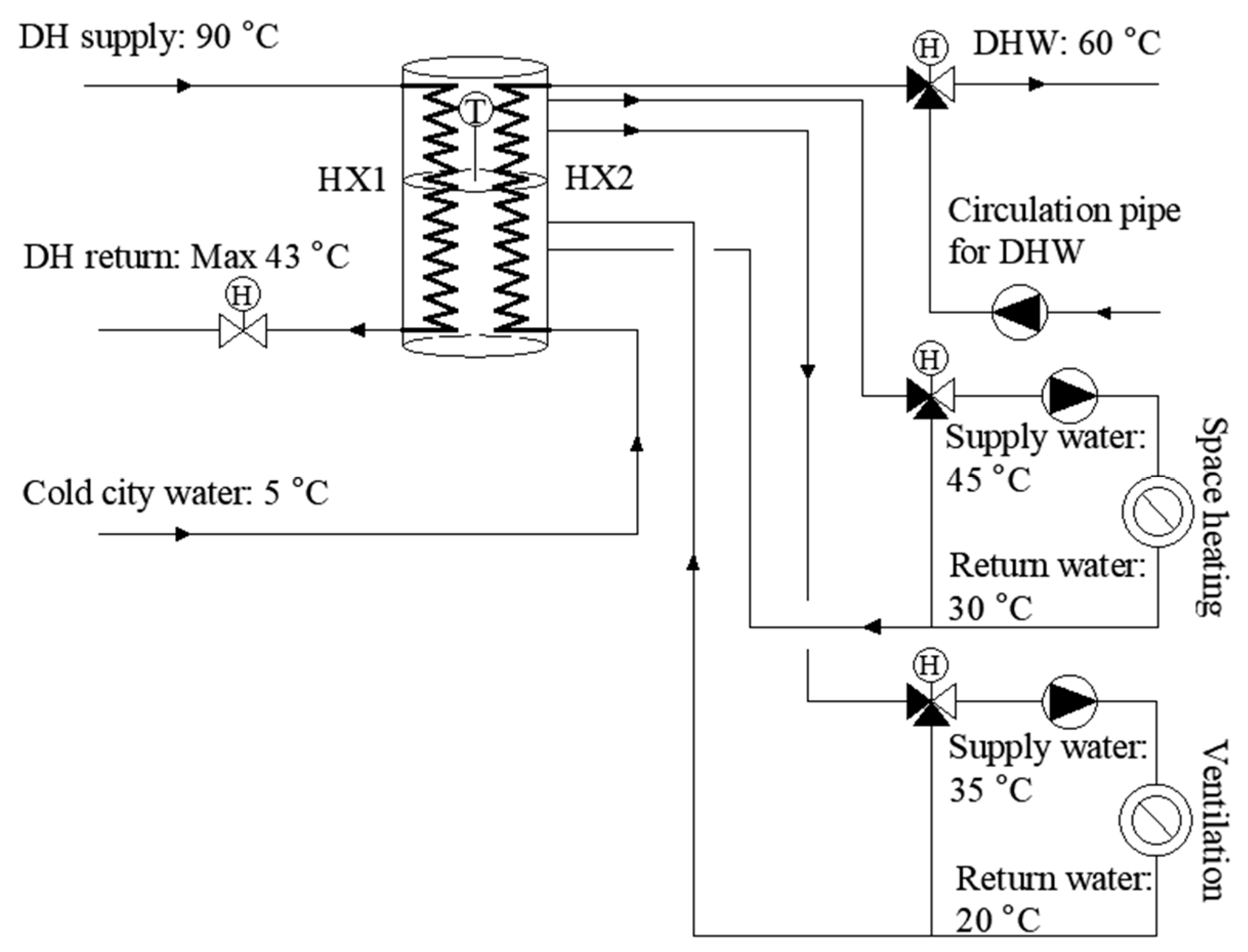
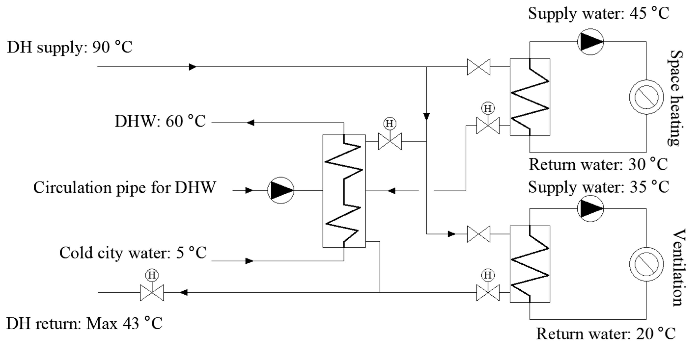
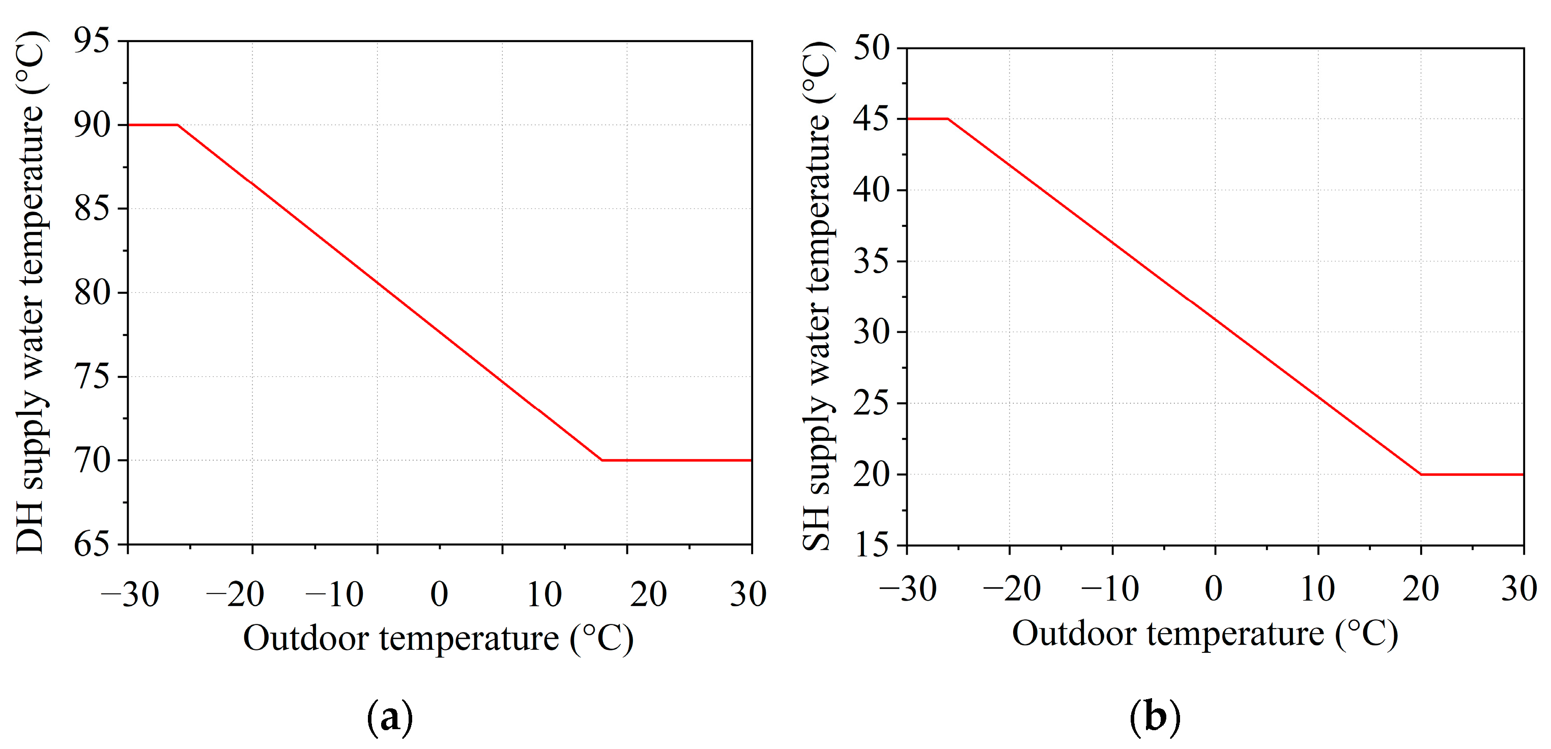
Figure 1 shows the original DH substation (Substation 1) without TES to supply heat to the office building. Design water temperatures (DH, space heating, ventilation, and DHW supply and return water) were set based on the Finnish guidelines [50] and they were also applied to the following substations (shown in Section 2.2.2 and Section 2.2.3). Therefore, the DH supply water temperature was designed at 90 °C for the coldest period. The minimum DH supply water temperature was 70 °C considering transmission and storage losses to guarantee that the DHW could be maintained at 60 °C during warmer periods of the building’s usage. For space heating, the maximum inlet water temperature was 45 °C and the design temperatures of radiators were set to 45/20 °C. The inlet water temperature of ventilation was constant, at 35 °C. The design ventilation return water temperature was 20 °C. The control curves of the DH and space heating supply water temperatures with different outdoor temperatures are shown in Figure 2. The control curves were the same with other substations shown in Section 2.2.2 and Section 2.2.3. The heating was stopped when the outdoor temperature reached 10 °C.
Therefore, the reference case has the actual peak heating power demand (125.2 kW) during the simulation period (see Section 2.3) including space heating, ventilation, and DHW power as shown in Table 1 with this substation layout. After that, TES was integrated into the substation for DH peak power dimensioning. The substation layouts with TES are presented in the following two sections. Therefore, this paper firstly studied how much DH peak power demand decreased after TES was installed in the substation. Secondly, this DH peak power was further reduced by limiting the mass flow of the primary district heat water flow.

2.2.2. DH Substation with TES and without Return Water Heat Exchangers

A 5 m3 hot water storage tank was selected for the purpose of peak shaving. The selection of the size took into account the installation conditions of the actual building. It was integrated into the substation, which is named as Substation 2, as shown in Figure 3. Two internal heat exchangers (HX1 and HX2) were installed in the water tank to avoid mixing primary DH water and DHW with storage tank water. The UA-values for the two internal heat exchangers HX1 and HX2 were set as 17.5 kW/K. There was a water temperature sensor equipped to measure the temperature where it was located.

2.2.3. DH Substation with TES and Return Water Heat Exchangers

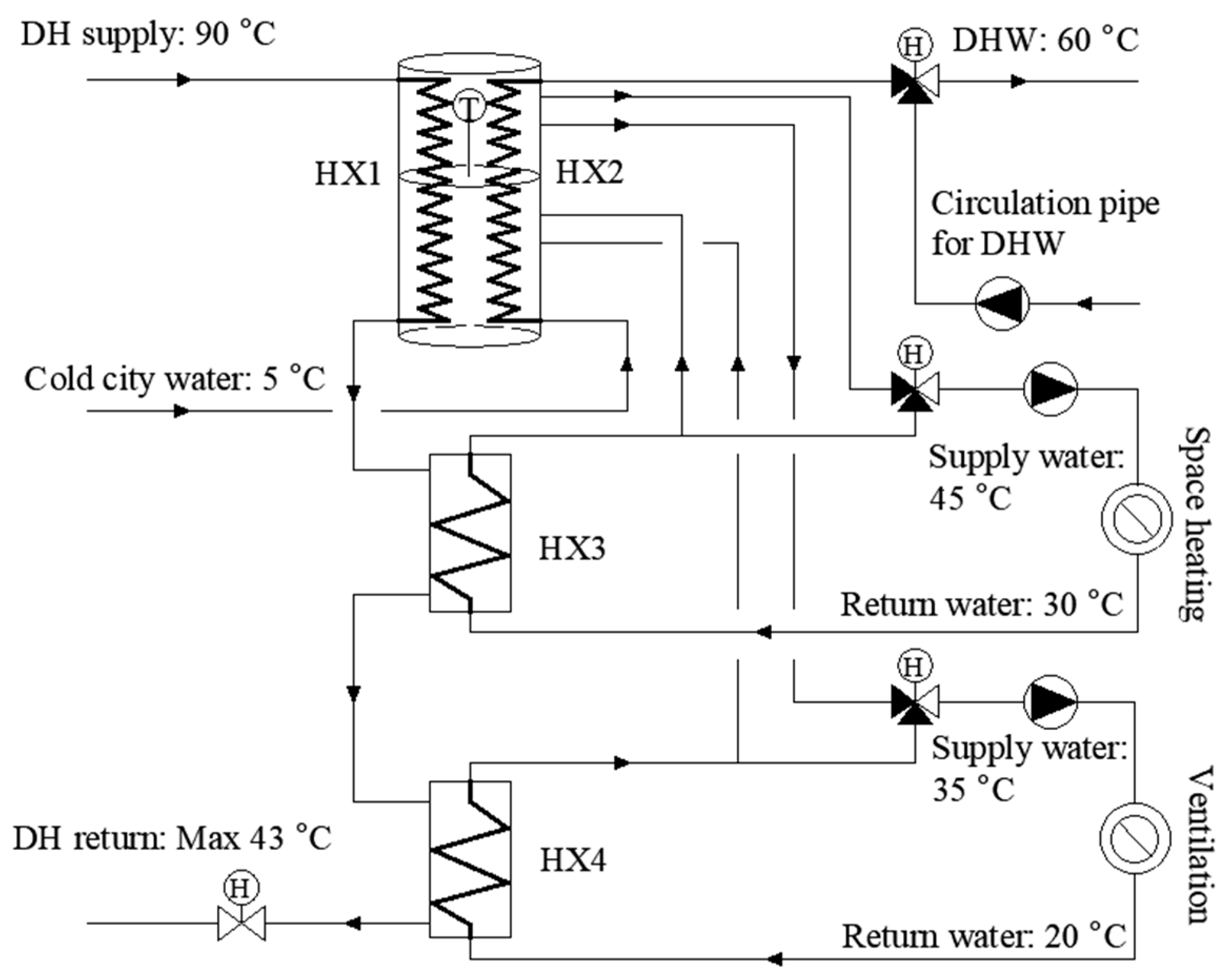
Figure 4 shows the layout of the Substation 3. Two return water heat exchangers (HX3 and HX4) were used to guarantee that the DH return temperature did not exceed 43 °C. It is the maximum allowed DH return water temperature level for a better DH system performance based on the Finnish guidelines [50]. The maximum DH supply water temperature, 90 °C, was also selected according to the guidelines [50], which is the same temperature as the other two substations mentioned before. The heat transfer at the rating of heat exchangers 3 and 4 (HX3 and 4) was 30 kW.

2.3. Simulation Tool and Weather Data

In this study, the building simulation tool IDA Indoor Climate and Energy (IDA ICE) was selected for simulating the office building [51]. It is a dynamic multi-zone simulation software providing a platform to model the characteristics of a building and its technical systems such as building geometry and structures, HVAC systems, and user profiles. It was validated against the EN 15255-2007 and EN 15265-2007 standards [52]. Moreover, several studies have validated that there is a strong justification for the simulation by IDA ICE in this paper [53,54,55].
In order to analyze different water temperature control strategies and peak power cutting effects on heating power variation, a stratified water tank model was established and simulated by IDA ICE. A one-dimensional storage tank model was used for simplification [56]. The stratified IDA ICE hot water storage tank can be configured for various configurations such as different heights and diameters, number of inlets and outlets with different positions, and with or without internal heat exchanger(s) [57]. The mixing factor (Fmixing), determined by IDA ICE, is the parameter of the storage tank to describe the heat exchange between adjacent layers. Therefore, the heat transfer between two adjacent layers (Qi) was defined in Equation (1).
Q i = A F m i x i n g Δ T i H i
where Qi is the heat transfer between two adjacent layers, W; i is the number of the layer; A is the cross-section area of the storage tank, m2; ∆Ti is the water temperature difference between two adjacent layers, °C; and Hi is the height of the layer, m. Thus, the total heat transfer between the bottom and top layers of the storage tank model was presented in Equation (2). The accuracy of the stratified IDA ICE hot water storage model has been proved by Alimohammadisagvand et al. [39].
Q = i = 1 n Q i
where Q is the total heat transfer between the bottom and top layers, W and n is the number of adjacent layers.
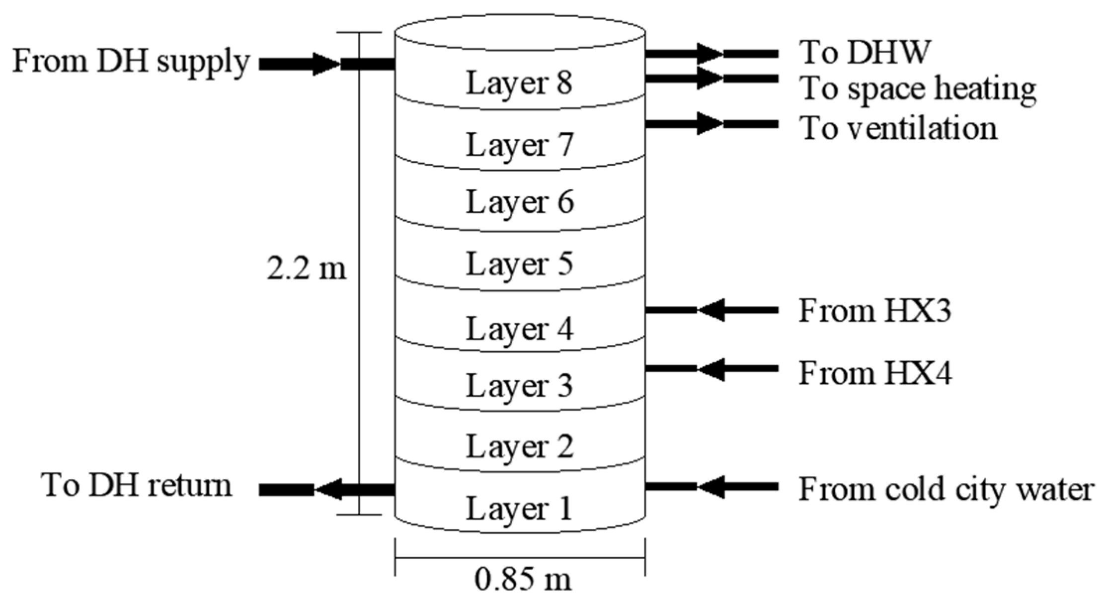
Considering the number of inlets and outlets and for the purpose of analyzing the water temperature sensor location change, the water tank was divided into eight layers with a total height of 2.2 m. The layout of the tank can be seen in Figure 5. Heat stored in layer 8 was supplied to both DHW and space heating, which indicates that DHW and space heating mainly gained heat from layer 8. Similarly, ventilation systems mainly gained heat from layer 7. The inlet positions of the building’s side were set according to their temperature levels. One temperature sensor was installed in the tank to measure the water temperature where it was located. When the storage tank supplied heat to the building, the measured temperature decreased. It was input to a PI controller. At every time step, the PI controller compared the measured temperature and the varied temperature setpoint, which has been defined in Section 2.4. If the measured water temperature was lower than the temperature setpoint, the PI controller would send a control signal to the DH motor valve to increase the primary DH supply water mass flow. Thus, more heat would be transferred to the tank water. When the measured water temperature was higher than the temperature setpoint, signals would be sent to decrease the mass flow. This study analyzed the impact of location changes of the temperature sensor on peak shaving. Therefore, the sensor was located on layers 7, 6, and 5 with 1.8 m, 1.5 m, and 1.2 m heights from the bottom of the tank depending on the case, separately.
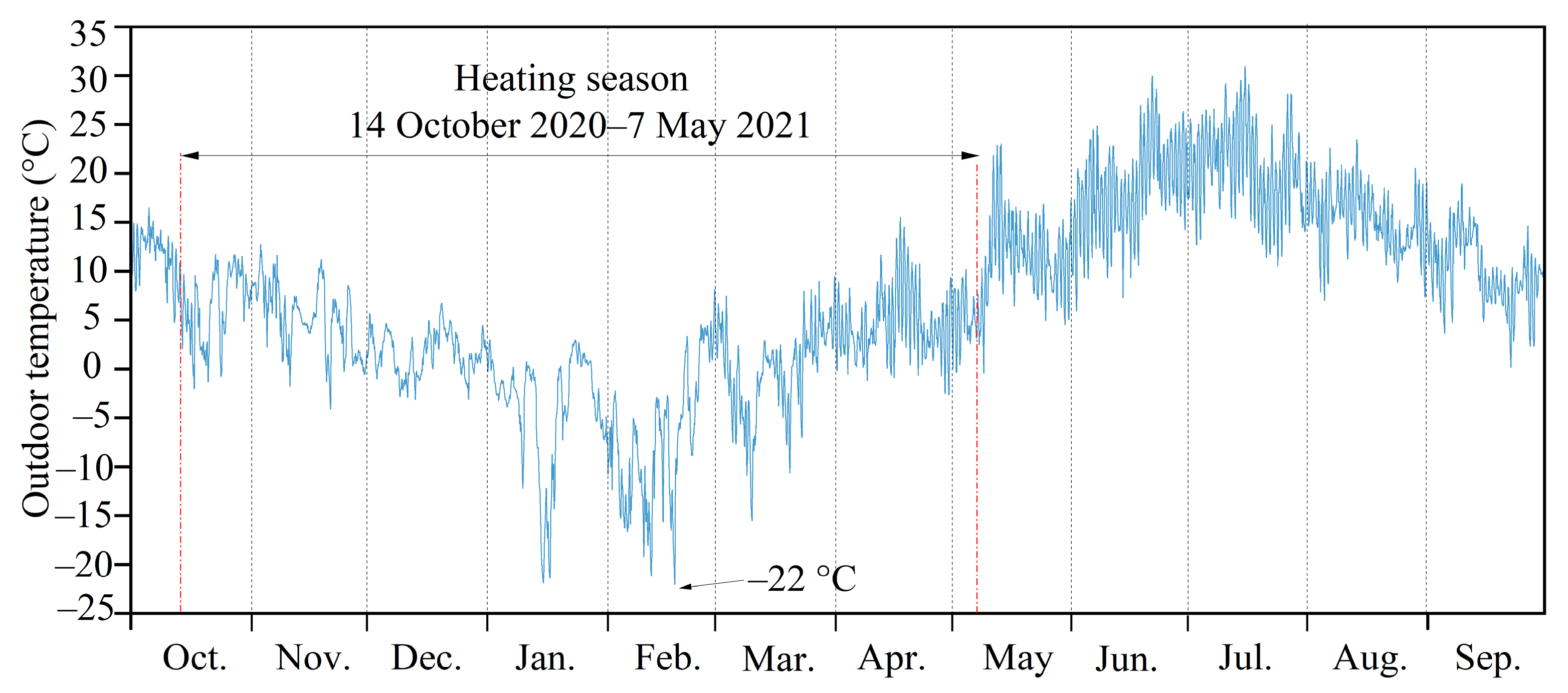
The simulation period is from October 2020 to September 2021 of Espoo in Finland. Hourly weather data measured at the weather stations of the Finnish Meteorological Institute in Tapiola and Kumpula [58] were used in the study, as shown in Figure 6. The weather data consist of outdoor temperature, relative humidity, wind speed and direction, and direct and diffuse solar radiation. January and February are the coldest two months. The minimum outdoor temperature is −22 °C. The heating season period was defined from 14 October 2020 to the 7 May 2021.

2.4. Peak Shaving Control for Short-Term Thermal Energy Storage Temperature

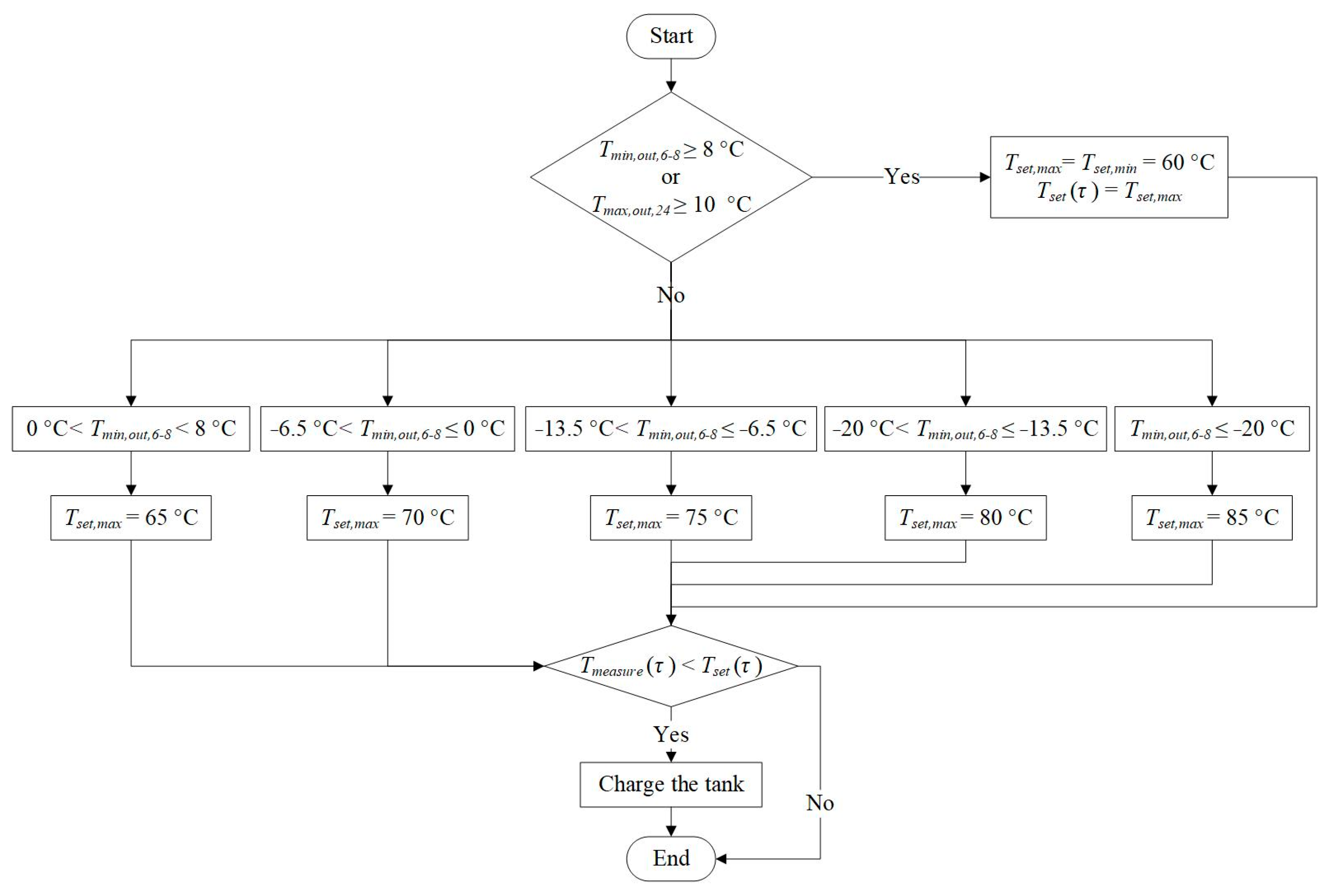
The control strategies were applied to change the water temperature setpoint of the tank in Substations 2 and 3 (Figure 3 and Figure 4). The purpose of the control algorithm was to decrease the peak heating power in the morning of workdays caused by the ventilation start. Figure 7 is the flow chart of the control algorithm to define the daily maximum temperature setpoint of the storage tank changed with different outdoor temperature ranges.
The daily maximum DH power varied with different outdoor temperatures. It was assumed that the future outdoor temperature of the following day was predicted without a prediction error. Therefore, in order to charge the tank properly to reduce the peak power demand without overcharging and exceeding the maximum return water temperature (43 °C), the maximum charging water temperature setpoint Tset,max was set according to the outdoor temperature variation, and it represented the maximum water temperature of the sensor located layer. The selected setpoints were considered based on pre-testing.
The Tset,max of the following day was determined based on the predicted outdoor temperature for that day. If the minimum outdoor temperature from 6 a.m. to 8 a.m. (Tmin,out,6–8) of the following workday was not below 8 °C or the maximum daily outdoor temperature of the following workday (Tmax,out,24) was not below 10 °C, the Tset,max of the following workday was set at 60 °C (Tset,min) which is the minimum temperature to guarantee DHW supply. The temperatures of the heating season defined as the period from 14 October 2020 to 7 May 2021 were divided into five ranges, as shown in Figure 7. Therefore, there were five different temperature setpoints of Tset,max (65 °C, 70 °C, 75 °C, 80 °C, and 85 °C). Since they were the maximum temperature setpoints, it also represented that the storage tank was charged to the maximum capacity under each outdoor temperature range when the measured temperature was equal to the maximum temperature setpoint. Tmeasure (τ) is the measured temperature per hour of the located layer. The sensor measured the water temperature. The tank was charged if the measured temperature Tmeasure (τ) was lower than the temperature setpoint Tset (τ).
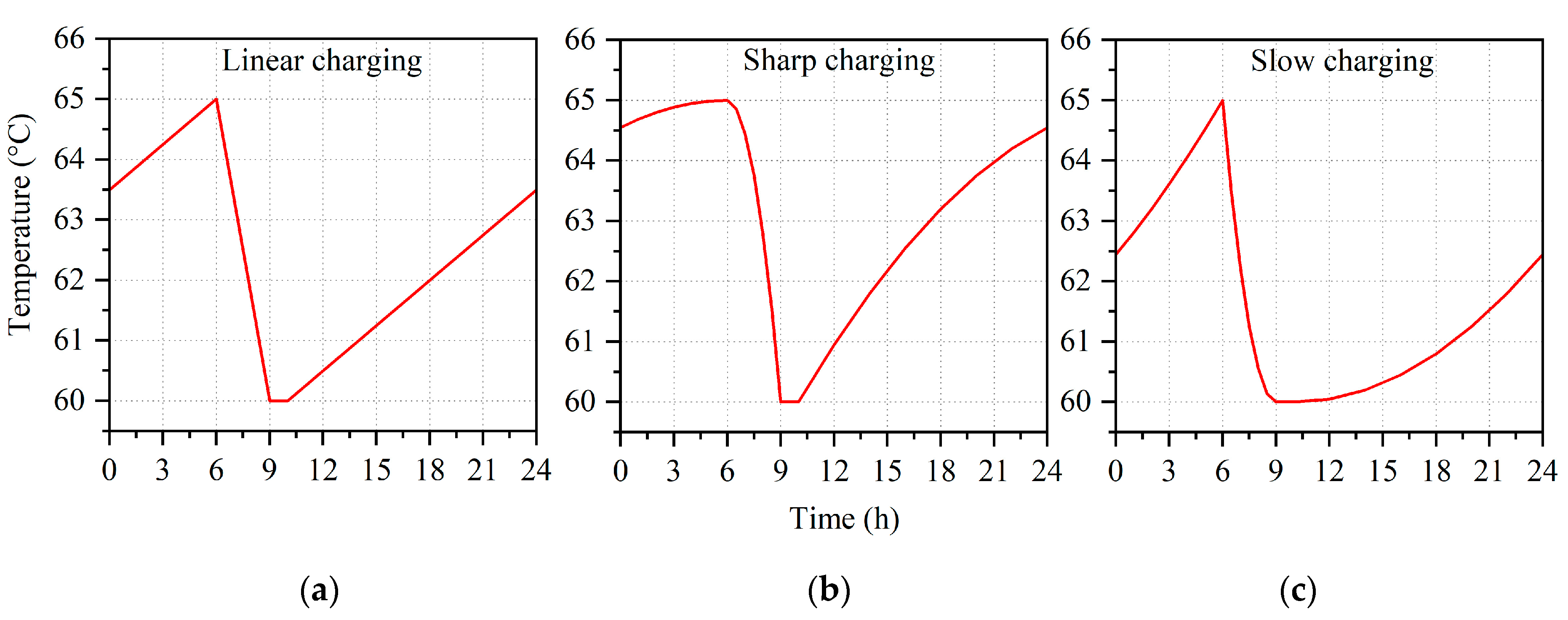
Figure 8 shows the peak shaving control curves of Tset (τ) as an example of the maximum temperature setpoint (Tset,max) at 65 °C. All the control curves follow the principle that the charging period was from 10 a.m. to 6 a.m. on the following day and the discharging period was from 6 a.m. to 9 a.m. for peak power reduction. The difference is that during the charging and discharging periods, the curves control different rates at which the water temperature of the storage increases and decreases. Therefore, the names of these curves such as linear charging mainly describe the characteristics during the charging period. Since the control curves were only applied on workdays, there were no charging or discharging actions during the holidays and weekends. The Tset (τ) during holidays and weekends was set as a constant and the value was determined based on the temperature setpoint at midnight on the last workday.
The control curves of linear charging were defined in Equation (3):
{ T s e t ( τ ) = k 1 τ + g 1 ,   0 τ < 6   T s e t ( τ ) = T s e t , m a x ,   τ = 6 T s e t ( τ ) = k 2 τ + g 2 ,   6 < τ < 9 T s e t ( τ ) = T s e t , m i n ,   9 τ < 10 T s e t ( τ ) = k 1 τ + g 3 ,   10 τ 24
where Tset (τ) is the temperature setpoint of each hour, °C; τ is the hour of a day, from 0 to 24; Tset,max is the maximum charging water temperature setpoint, °C; Tset,min is the minimum charging water temperature setpoint, which was set as 60 °C; k1, g1, k2, g2, and g3 are the factors changed with different Tset,max. There were five different Tset,max setpoints so that there were five related groups of k1, g1, k2, g2, and g3 values.
The following equations describe the control curves for sharp (Equation (4)) and slow (Equation (5)) charging:
{ T s e t ( τ ) = a 1 ( τ 6 ) 2 + T s e t , m a x ,   0 τ < 6   T s e t ( τ ) = T s e t , m a x ,   τ = 6 T s e t ( τ ) = a 2 ( τ 6 ) 2 + T s e t , m a x ,   6 < τ < 9 T s e t ( τ ) = T s e t , m i n ,   9 τ < 10   T s e t ( τ ) = a 1 ( τ 30 ) 2 + T s e t , m a x ,   10 τ 24
{ T s e t ( τ ) = a 1 ( τ + 14 ) 2 + T s e t , m i n ,   0 τ < 6   T s e t ( τ ) = T s e t , m a x ,   τ = 6 T s e t ( τ ) = a 2 ( τ 9 ) 2 + T s e t , m i n ,   6 < τ < 9 T s e t ( τ ) = T s e t , m i n ,   9 τ < 10   T s e t ( τ ) = a 1 ( τ 10 ) 2 + T s e t , m i n ,   10 τ 24
where a1, a2 are the factors above zero changed with the different Tset,max. Therefore, there were also five related groups of a1, a2 values. Actually, there were only 2% of the days in the heating season when the Tset,max was set to 85 °C. Nearly half of the days had a Tset,max of 65 °C and 26.4% of the days in the heating season had a Tset,max of 70 °C, which was the second highest proportion.

2.5. Definition of Flexibility Factors

Power and energy flexibility factors were defined in Equations (6)–(9) to describe the short-term TES charging and discharging potential [59]. Power flexibility factor P+ was introduced to describe the charged power during the tank charging period compared with the reference case with substation layout l without the storage tank (Figure 1). P represents the reduced hourly heating power by the storage tank discharging during peak hours. Therefore, FF+ is the percentage of the tank charging energy during off-peak periods within the whole heating season. FF is the total percentage of the heating energy reduction by the tank discharging during peak power periods.
P + = P c h a r g i n g P r e f
P = P d i s c h a r g i n g P r e f
F F + = 0 τ h s p + d t 0 τ h s p r e f d t
F F = 0 τ h s P d t 0 τ h s p r e f d t
where Pref is the power demand of the reference cases without short-term TES, kW; Pcharging is the heating power when the storage tank temperature setpoint increases for charging, kW; Pdiscarging is the heating power when the storage tank temperature setpoint decreases for discharging, kW; FF+ is the percentage of charged energy during the heating season compared with a reference case without TES (Figure 1); FF is the percentage of discharged energy; and τhs is the hours of the heating season, h.

2.6. Description of Simulated Cases

Table 3 describes the simulated cases. The results during the heating season were analyzed in this study. Firstly, the office building was simulated without a short-term thermal storage tank as the reference case (Substation 1, shown in Figure 1). Secondly, two cases of the linear charging control curve with (Substation 3, shown in Figure 4) and without (Substation 2, shown in Figure 3) DH return water heat exchangers were simulated to compare the effects on the return temperature. After that, cases with different control curves and sensor positions were evaluated in Section 3.2 and Section 3.3. Section 3.4 investigated the peak shaving potential and flexibility of the cases with water temperature control and peak power cutting, which was realized by cutting the mass flow of the primary DH supply water as show in Table 3. In this study, we analyzed hourly average results for all the cases.

3. Results

The DH return water temperature changes after the installation of the return water heat exchangers are proposed firstly in Section 3.1. After that, the effects of different charging and discharging strategies of short-term TES on heating power variation are analyzed and compared in Section 3.2. The way in which the heating power would vary with the location change of the water tank temperature sensor is investigated in Section 3.3. The results of the peak shaving potential and their flexibility are presented in Section 3.4 and Section 3.5. Finally, the impacts of peak shaving on indoor air conditions are discussed in Section 3.6.

3.1. DH Return Water Heat Exchangers

Table 4 lists the maximum, minimum, and average DH return water temperatures before (Substation 2, shown in Figure 3) and after (Substation 3, shown in Figure 4) installing the return water heat exchangers during the heating season. There is a significant decrease in the maximum return water temperature by 25.1 °C because of the return water heat exchangers installation. Moreover, the average return water temperature drops by 23 °C. It reflects that the installation of return water heat exchangers decreases the maximum and average return water temperatures, which guarantees that the return water temperature cannot exceed the maximum allowed temperature of 43 °C. Because of these results, the return water heat exchangers are used in the following cases.

3.2. Different Charging and Discharging Strategies of Short-Term Thermal Energy Storage

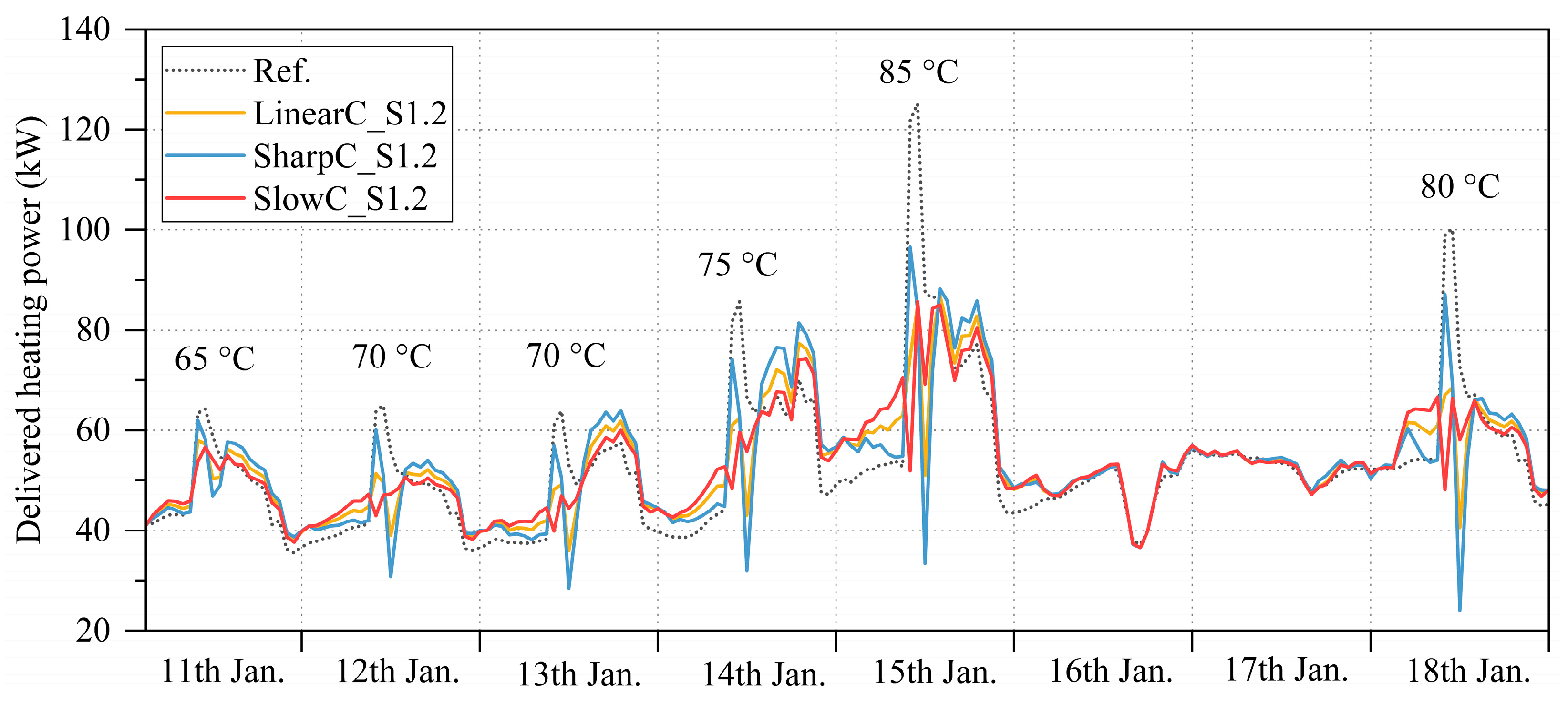
Figure 9 shows the delivered heating power with different control curves of a period in January with the peak heating power demand of the whole heating season. Another reason for choosing this period for analysis is that it has fluctuated outdoor temperatures, which means that it can reflect the DH power variation under different control curves with all five maximum temperature setpoints (Tset,max). The maximum delivered heating peak power is 125.2 kW of Substation 1 (Figure 1) including space heating, ventilation, DHW, and heat losses of the systems. The temperatures marked in the figure are the maximum charging water temperature setpoints (Tset,max) for each day. It indicates that all the control curves can significantly decrease the peak power, especially on colder days (14th, 15th, and 18th). The linear and slow curves behave slightly better, and the slow curve is the best. It shows that the peak powers of the case with sharp charging are all higher than other cases on colder days (14th, 15th, and 18th), and the peak powers are only slightly reduced on warmer days (11th–13th). In addition, the slow charging curve controls the tank to store more heat during the night. Therefore, for the purpose of flattening the heating power curve, the slow charging curve behaves better than the linear one and because of this, the slow charging curve is used in the following cases.

3.3. Location of Temperature Sensor

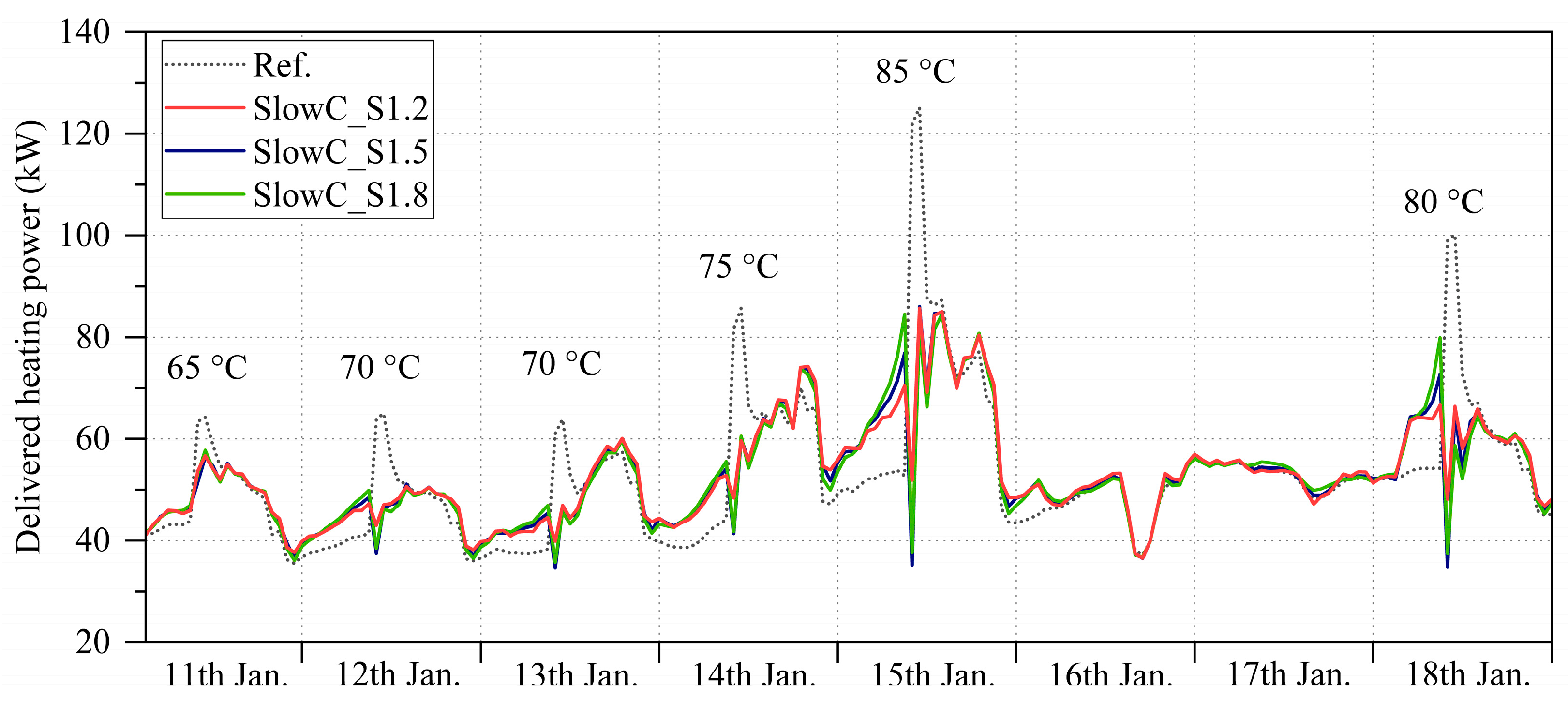
Figure 10 shows the delivered heating power with different sensor positions. The power curves vary more with the increase of the sensor position height from the bottom of the storage tank. A higher position of the sensor means less storage capacity so that less heat can be discharged in the morning. For the warmer days (11th–13th), there is almost no difference with a sensor position change. However, on the colder days (14th, 15th, and 18th), the decrease of the outdoor temperature exposes the problem of insufficient heat charging of 1.5 m and 1.8 m in height. Therefore, a 1.2 m sensor height is the most suitable to guarantee that enough heat is stored for discharging and this sensor position is chosen in the following cases.

3.4. Peak Shaving

The delivered heating power variations of mass flow cutting cases during a period in January with the peak heating power demand of the whole heating season can be seen in Figure 11. The mass flows of the primary DH supply water were cut by 20%, 30%, and 40% compared with the maximum mass flow of the slow charging case (SlowC_S1.2). The 20% mass flow cutting only has an obvious decrease of the peak power on the 15th of January when the peak power demand of the whole heating season is at the maximum, with the highest charging temperature setpoint at 85 °C. For the warmer days (11th–13th), the 30% mass flow cutting has no obvious effect on the heating power variation. The reason is that the actual mass flows during these days are around or lower than 70% of the maximum mass flow of the slow charging case (SlowC_S1.2). For the colder days (14th, 15th, and 18th), power is maintained at around 60 kW for over half of the time after 30% of mass flow cutting to guarantee enough heat supply. The power variation curve is the flattest by 40% of mass flow cutting because the system needs to operate with the maximum allowable mass flow most of the time for a sufficient heat supply.
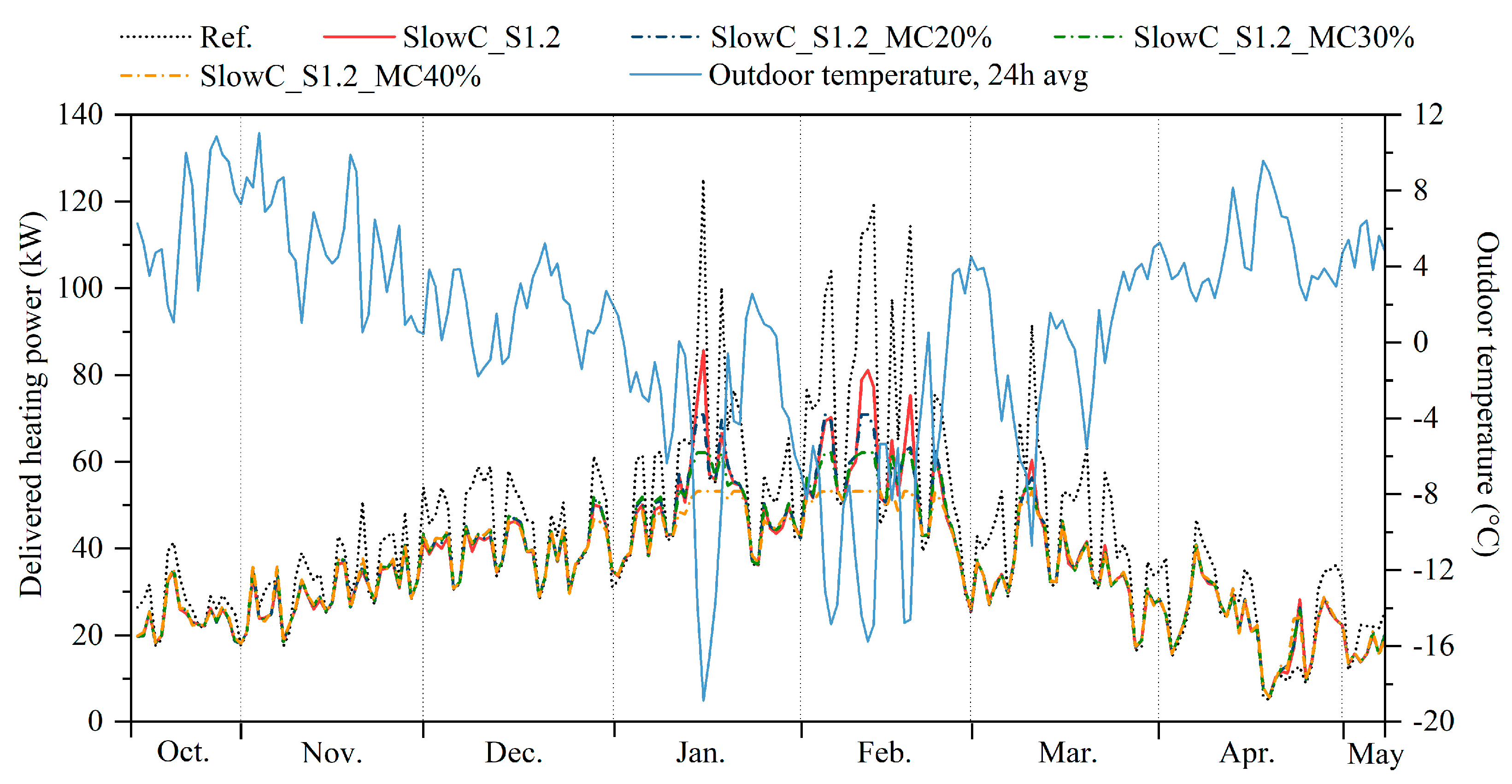
The daily maximum hourly peak power curves with and without TES or mass flow cutting during the heating season are depicted in Figure 12. The light blue line is the daily average outdoor temperature curve. It can be seen that the application of short-term thermal storage with slow charging control effectively decreases the daily maximum peak power during the heating season. The lower the outdoor temperature is, the greater the daily maximum peak power reduces. In the warmer months (October to December and March to May), the daily maximum peak power is almost unchanged by mass flow cutting. On the contrary, on the days with a daily average outdoor temperature around or lower than −16 °C, the daily maximum peak power reduces significantly as mass flow cuts more. With 40% of the primary DH supply water mass flow cutting, almost half of the period in January and the entire of February were limited to nearly 55 kW for maximum heating power supply.
The daily maximum peak powers are higher than these of the reference case in April from the 19th to 25th. The values of this week are the lowest of the reference case. The PI controller decided to charge the tank when the measured water temperature was lower than the temperature setpoint. Therefore, a lower daily maximum peak power meant that the setpoint was reached easily, which led to more frequent charging and discharging actions within shorter periods. The total heat consumption of this week with storage is similar to that of the reference case while the power is more fluctuated.
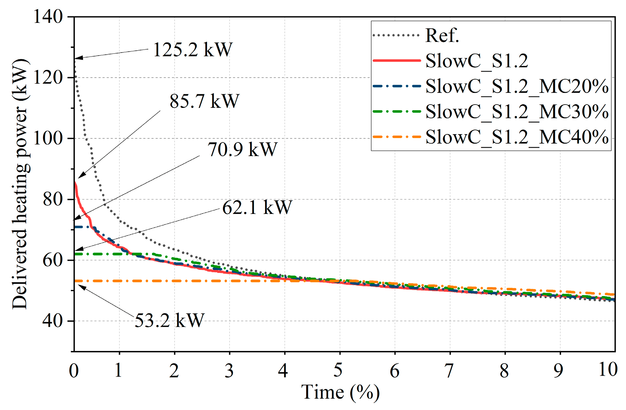
Figure 13 delineates the heating season duration for 10% of the delivered heating power. After the installation of TES in the substation (Figure 4), the maximum peak power of the case with slow charging decreases by 39.5 kW compared with the reference one, which is about 31.5%. In addition, the maximum peak power is further limited via cutting the mass flow of the primary DH supply water. Compared with the case SlowC_S1.2 with the maximum heating power of 85.7 kW, the maximum power was separately cut by 17%, 28%, and 38% by cutting 20%, 30%, and 40% of the SlowC_S1.2 case maximum mass flow. Compared with the reference case, the mass flow cutting approach reduces around 43%, 50%, and 58% of the maximum heating power, respectively.
Table 5 lists the duration proportions of different delivered heating power ranges of the reference case and peak shaving cases with and without mass flow cutting during the heating season. For the case SlowC_S1.2, it indicates that because of the storage, the duration proportion of the delivered heating power from 20 kW to 60 kW is 3.4 percentage units higher than that of the reference, while it drops by 2.5 percentage units when the heating power is below 20 kW. In addition, it significantly reduces the delivered heating power duration ratio when the power is higher than 70 kW. It illustrates that the power is shifted from high-peak to off-peak periods. After 30% mass flow cutting, in order to supply enough heat to the office building, the duration proportion of delivered heating power within 60 to 70 kW is 1 percentage unit higher compared with the reference, SlowC_S1.2 and SlowC_S1.2_MC20% cases. Similarly, in the range of 50 to 60 kW, compared with the reference, it increases 4.6 percentage units after 40% mass flow cutting. It is about 3.5 percentage units higher than the cases with storage (SlowC_S1.2) and 20% or 30% mass flow cutting (SlowC_S1.2_MC20%, SlowC_S1.2_MC30%).
Table 6 shows the return water temperatures of the peak shaving cases. It indicates that the maximum return water temperatures are all below the maximum allowed temperature of 43 °C. After mass flow cutting, the maximum return water temperatures decrease while there is almost no difference in minimum and average return water temperatures.

3.5. Power and Energy Flexibilities

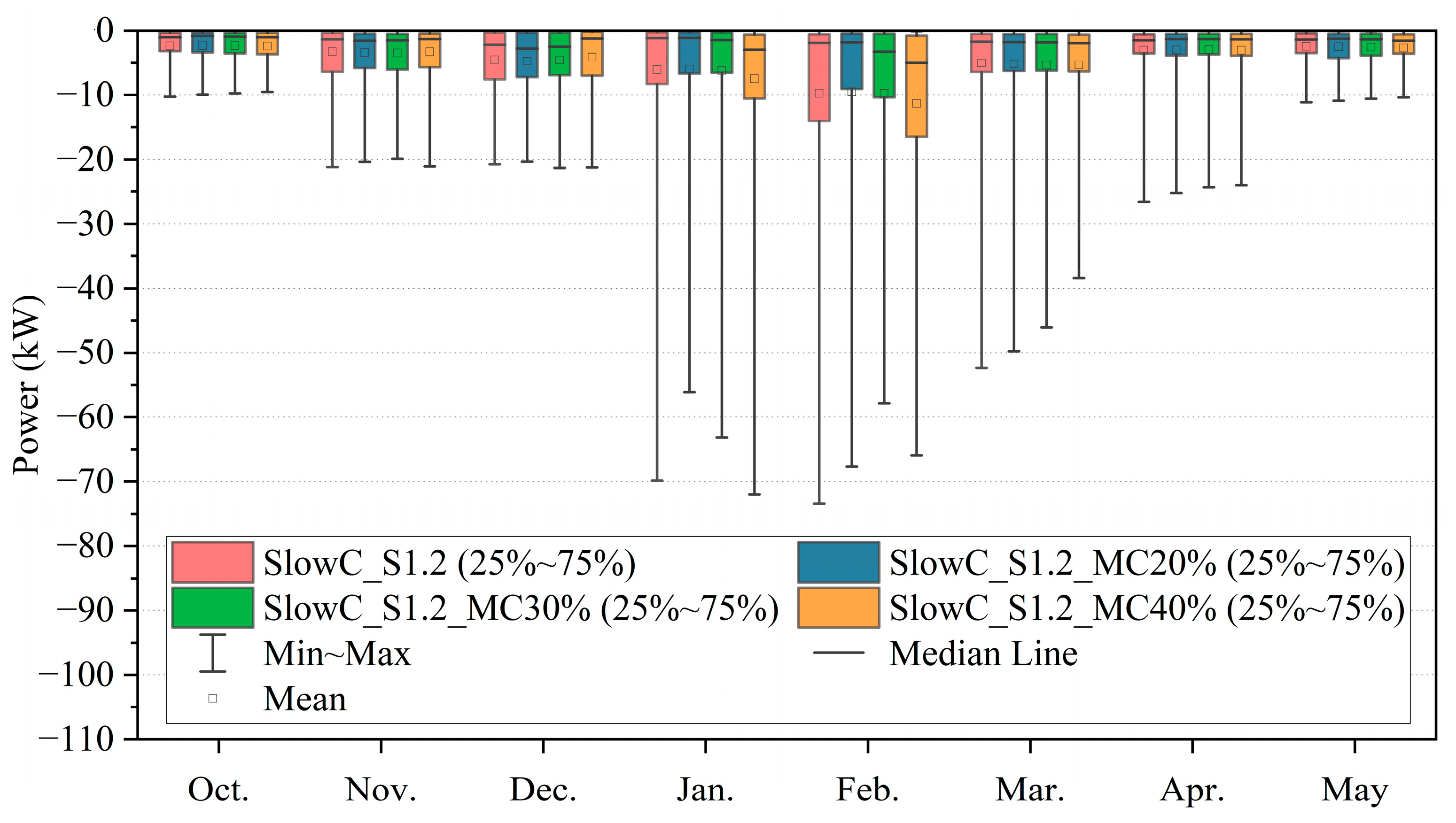
Figure 14 and Figure 15 are the box charts of flexibility factors P+ and P (see Equations (6) and (7)) for each month during the heating season. The range is from the minimum to the maximum. The box body contains 50% of the values with the range from the lower quartile (25%) to the upper quartile (75%). The maximum P+ values are quite similar of the case SlowC_S1.2 in October, November, December, and May. The maximum P+ is approximately 16 kW and the minimum P is −70 kW, which indicates that more power is shifted from high-peak periods. It also illustrates that the slow charging control curve can be effectively employed to prevent a substantial rise in the heating power during charging periods (10 a.m.–6 a.m. on the following day). In addition, minimum P values have a more sensitive change when the outdoor temperature drops. Moreover, there is no significant relationship between the degree of mass flow cutting and the variation of power flexibility values. However, it can be found in almost all the cases that in January, February, and March, when the maximum flexibility factor P+ increases, there is also a rise of the corresponding minimum flexibility factor P.
Table 7 lists the energy flexibility factors FF+ and FF of the peak shaving cases. The short-term thermal storage integration supplies about 5% of energy flexibility to shift energy to off-peak periods. In addition, 5.3% FF+ and −4.3% FF for the case with slow charging (SlowC_S1.2) reflect 1% of heat losses. The flexibility factor FF+ increases gradually with more mass flow cut. Similarly, the flexibility factor FF decreases when the mass flow is more limited, so the power curves of these cases are flatter. However, the application of mass flow cutting does not lead to additional heat losses.

3.6. Indoor Temperature Conditions

Figure 16 shows the heating season (14 October 2020–7 May 2021) duration of indoor air temperatures in the coldest and warmest rooms in the office building. The coldest room is a meeting room, and the warmest room is an office room. The coldest room is the room with the lowest minimum indoor air temperature in the office building. The warmest room is defined as the one with the highest minimum indoor air temperature during the heating season among other rooms.
The indoor air temperature ranges of the cases with storage (Slow C_S1.2) and with storage and mass flow cutting by 20% and 30% (Slow C_S1.2_MC20%, Slow C_S1.2_MC30%) fulfill the target indoor temperatures mentioned in Section 2.1. However, when 40% of the mass flow is cut, there is an obviously insufficient heating supply on the workdays in January and February so that the indoor air temperature drops below 20 °C. The minimum indoor air temperature of the coldest room drops to 18.8 °C. There are totally 28 h (0.6%) in the coldest room when the hourly indoor air temperature is below the minimum acceptable indoor air temperature (20 °C) during the heating season caused by 40% mass flow cutting. Moreover, it happens almost exclusively during occupied hours. Therefore, except the case with 40% mass flow cutting, cases with slow charging control and further mass flow cutting up to 30% can effectively decrease the heating peak power without sacrificing thermal comfort. There is a week in April (19th–25th) when the maximum daily outdoor temperature was above 10 °C during the daytime. Because of the coldest room orientation to gain more solar radiation, its indoor air temperatures are higher than those of the warmest room during these days (90–100% duration period).

4. Discussion

To decrease CO2 emissions and realize climate neutrality, flexible buildings in a DH network are essential for increasing the proportion of intermittent renewable energies. The results indicate that the application of short-term TES significantly decreases the office building daily peak power caused by the ventilation system’s morning start during the heating season. In addition, peak power cutting provides a further decrease of the DH peak power demand. It is beneficial for Finnish consumers because of the power fee [60]. The yearly power fee is charged based on the annual DH peak power level. Therefore, the higher the DH peak power demand of a building, the more the Finnish consumers pay for power fees. Therefore, it could decrease costs for consumers.
For DH producers, the large-scale application of the integration of short-term TES into substations for peak shaving decreases the need of the total generation capacity, which could become economically and ecologically profitable. On one hand, less delivered power would be transported from plants to substations during peak-power periods because the short-term TES is in there. As a result, pipe sizes for transportation could be reduced while heat distribution pipes in buildings from a substation to room units and air handling units could remain the same. On the other hand, since urbanization is accelerating, the number of heating consumers is gradually increasing. It will eventually cause the existing heating system to be unable to meet the rising heat demand. Since peak shaving by short-term TES reduces the peak power demand of DH systems, more consumers could be connected to the same generation network. DH producers may gain more profits from more customers while saving money on new or replacement generators.
What is more, it indicates that the large-scale application of short-term TES into substations could be an effective strategy to replace fossil fuels with renewable energy sources and improve the performance of DH units’ operation. DH producers would pay less expenses for CO2 emissions.
This paper mainly focuses on analyzing the impact of different water temperature control curve characteristics on heating power variation and peak shaving potential by TES and peak power cutting. Therefore, DH energy cost savings and investment costs of the facilities were not considered in this paper. A building owner who typically owns the substation pays for short-term TES installation. DH peak power demand has an impact on a power fee for building owners. In addition, DH producers save expenses for CO2 emissions, gain revenues from better system performance, and have more possible connected consumers because of the short-term TES application. Therefore, the DH energy cost savings both for building owners and DH producers, payback period, and life cycle cost (LCC) analysis should be carried out in further studies considering DH energy prices, DH power fees, investment, etc.
Through the establishment of the substation model, it indicated that considering the limitation of the DH return water temperature, the short-term hot water storage was not allowed to be fully charged. The most proper option was only to charge the amount of heat that could meet the peak shaving purpose unless the primary return water temperature could exceed the maximum allowed temperature. Charging more heat in the storage tank means that there is extra heat that is not supplied to the building so the return water temperature increases. Furthermore, it will cause a more serious rebound effect. In addition, the outdoor temperature variation should be taken into account. The outdoor temperature varied during the day. Usually, it reached the maximum temperature in the afternoon. The DH return water temperature could be higher than the limitation when charging the thermal storage during the daytime. Therefore, the charging time of the storage should be controlled with consideration of the outdoor temperature variation.
The maximum allowed primary return water temperature of 43 °C used in this study is based on the Finnish guideline [50]. However, according to different guidelines or DH systems in different countries, the maximum allowed temperature could be varied. For example, in Germany, the maximum allowed temperature could be lower than 40 °C when the primary supply water temperature is 70 °C [61]. For low-temperature DH in Germany, Denmark, Finland, Norway, and Great Britain, the maximum allowed return water temperatures could be 25 to 40 °C with 40 to 60 °C supply water temperature [61]. Thus, the control strategies for short-term TES charging need to be adjusted to different maximum allowed temperature levels.
Similarly, the minimum acceptable indoor air temperature (20 °C) of this study was set based on the Finnish building code [45] and it also fulfils the thermal environment category II of the EN 16798-1 standard [46]. According to this study, the minimum acceptable indoor temperature is violated when the peak power is cut by 40% and the DHW supply water temperature cannot be guaranteed during these periods. However, considering different national guidelines, the minimum acceptable indoor air temperatures could be different. For example, in France, the upper limits of the heating temperature are recommended to be, on average, 19 °C for office buildings during occupied hours [62]. Therefore, local guidelines and target values of the acceptable indoor air temperature range need to be taken into account to determine a proper peak power limiting degree.
There are many factors that could affect DH return water temperature which is mainly related to the return temperature from the short-term hot water storage. For example, the change of primary supply mass flow, heights of space heating, ventilation, and DHW inlets and outlets connected to storage, or dimensioning of heat exchangers will increase or decrease the return water temperature. The parameters chosen in this study are specific to the characteristics of the studied office building and the DH substation configuration. However, the water tank temperature control strategy of charging and discharging could be applied to other district heated buildings in other cold regions. It could decrease the peak power caused by space heating, ventilation, DHW, or a combination of them. The selection of the storage tank size mainly considered the installation conditions of the actual building. For further study, tank size optimization should be taken into account.

5. Conclusions

The aim of this paper is to shave the district heating peak power of a Finnish office building by short-term thermal energy storage without exceeding the maximum allowed district heating return water temperature. The district heating return water temperature changed after the installation of the return water heat exchangers were first analyzed. After that, the different water temperature control strategies, water tank temperature location change, and peak power cutting effects on the heating power variation and peak shaving potential were investigated and flexibility factors were employed to describe the short-term TES charging and discharging potential. Detailed conclusions are listed below:
The installation of return water heat exchangers can decrease the district heating return water temperature so that it guarantees that the return water temperature cannot exceed the Finnish maximum allowed limitation of 43 °C.
Linear and slow storage tank charging control curves can effectively help to decrease the district heating peak power demand, especially on colder days while the sharp charging curve does not respond on time for peak cutting on warmer days. The slow charging curve controls the water tank to store more heat at night. Therefore, for the purpose of flattening the heating power curve, the slow charging curve behaves better than the linear one. In addition, a lower sensor position is more suitable to increase the storage capacity and guarantee enough heat for discharging.
The application of short-term thermal storage with slow charging control effectively decreases the daily maximum peak power during the heating season. The maximum peak power of the case with slow charging decreases by 39.5 kW compared with the reference, which is about 31.5%. The lower the outdoor temperature is, the greater the daily maximum peak power reduces. In addition, peak power cutting by around 30% provides an additional peak power reduction without sacrificing thermal comfort.
In summary, installing TES to a substation is useful for decreasing the daily maximum peak power during the heating season. Through the analysis of flexibility factors, more power is shifted from high-peak periods without causing additional peaks. In addition, compared with the reference office building without TES, it reduces, at most, 50% of the DH peak power demand by peak power limiting without sacrificing thermal comfort.
Author Contributions

Conceptualization, Y.J., J.J. and R.K.; methodology, Y.J., J.J. and R.K.; software, Y.J., J.J. and R.K.; validation, Y.J., J.J. and R.K.; formal analysis, Y.J.; investigation, Y.J.; resources, J.J. and R.K.; data curation, J.J. and R.K.; writing—original draft preparation, Y.J.; writing—review and editing, J.J. and R.K.; visualization, Y.J.; supervision, R.K.; project administration, R.K.; funding acquisition, R.K. and J.J. All authors have read and agreed to the published version of the manuscript.

Funding

This study is part of FINEST Twins. The FINEST Twins project is funded by the European Union (Horizon 2020 Programme, Grant No. 856602) and the Estonian government.

Institutional Review Board Statement

Not applicable.

Informed Consent Statement

Not applicable.

Data Availability Statement

The data presented in this study are shown in the paper.

Conflicts of Interest

The authors declare no conflict of interest.

References

  1. European Commission. Energy Performance of Buildings Directive. Available online: https://ec.europa.eu/energy/topics/energy-efficiency/energy-efficient-buildings/energy-performance-buildings-directive_en#energy-performance-of-buildings-standards (accessed on 1 July 2021).
  2. European Commission. EU Climate Action—2030 Climate and Energy Framework. Available online: https://ec.europa.eu/clima/policies/strategies/2030_en (accessed on 1 July 2021).
  3. Finnish Government. Programme of Prime Minister Sanna Marin’s Government 10 December 2019. Inclusive and Competent Finland—A Socially, Economically and Ecologically Sustainable Society. Available online: http://urn.fi/URN:ISBN:978-952-287-811-3 (accessed on 1 July 2021).
  4. IEA (International Energy Agency). Energy Policies of IEA Countries: Finland 2018 Review. Available online: https://www.iea.org/reports/energy-policies-of-iea-countries-finland-2018-review (accessed on 1 July 2021).
  5. Finnish Energy. Energy Year 2020—District Heating. Available online: https://energia.fi/en/newsroom/publications/energy_year_2020_-_district_heating.html#material-view (accessed on 1 July 2021).
  6. Robert, F.C.; Sisodia, G.S.; Gopalan, S. A critical review on the utilization of storage and demand response for the imple-mentation of renewable energy microgrids. Sustain. Cities Soc. 2018, 40, 735–745. [Google Scholar] [CrossRef]
  7. Shan, K.; Wang, S.; Yan, C.; Xiao, F. Building demand response and control methods for smart grids: A review. Sci. Technol. Built Environ. 2016, 22, 692–704. [Google Scholar] [CrossRef]
  8. Johansen, K.; Johra, H. A niche technique overlooked in the Danish district heating sector? Exploring socio-technical per-spectives of short-term thermal energy storage for building energy flexibility. Energy 2022, 256, 124075. [Google Scholar] [CrossRef]
  9. Le Dréau, J.; Heiselberg, P. Energy flexibility of residential buildings using short term heat storage in the thermal mass. Energy 2016, 111, 991–1002. [Google Scholar] [CrossRef]
  10. Aoun, N.; Bavière, R.; Vallée, M.; Aurousseau, A.; Sandou, G. Modelling and flexible predictive control of buildings space-heating demand in district heating systems. Energy 2019, 188, 116042. [Google Scholar] [CrossRef]
  11. Arteconi, A.; Costola, D.; Hoes, P.; Hensen, J.L.M. Analysis of control strategies for thermally activated building systems under demand side management mechanisms. Energy Build. 2014, 80, 384–393. [Google Scholar] [CrossRef] [Green Version]
  12. Christensen, M.H.; Li, R.; Pinson, P. Demand side management of heat in smart homes: Living-lab experiments. Energy 2020, 195, 116993. [Google Scholar] [CrossRef]
  13. Yang, X.; Pan, L.; Guan, W.; Tian, Z.; Wang, J.; Zhang, C. Optimization of the configuration and flexible operation of the pipe-embedded floor heating with low-temperature district heating. Energy Build. 2022, 269, 112245. [Google Scholar] [CrossRef]
  14. Van Oevelen, T.; Vanhoudt, D.; Johansson, C.; Smulders, E. Testing and performance evaluation of the STORM controller in two demonstration sites. Energy 2020, 197, 117177. [Google Scholar] [CrossRef]
  15. Foteinaki, K.; Li, R.; Péan, T.; Rode, C.; Salom, J. Evaluation of energy flexibility of low-energy residential buildings con-nected to district heating. Energy Build. 2020, 213, 109804. [Google Scholar] [CrossRef]
  16. Dominković, D.F.; Gianniou, P.; Münster, M.; Heller, A.; Rode, C. Utilizing thermal building mass for storage in district heating systems: Combined building level simulations and system level optimization. Energy 2018, 153, 949–966. [Google Scholar] [CrossRef]
  17. Guelpa, E.; Verda, V. Thermal energy storage in district heating and cooling systems: A review. Appl. Energy 2019, 252, 113474. [Google Scholar] [CrossRef]
  18. Mazhar, A.R.; Liu, S.; Shukla, A. A state of art review on the district heating systems. Renew. Sustain. Energy Rev. 2018, 96, 420–439. [Google Scholar] [CrossRef]
  19. Buffa, S.; Fouladfar, M.H.; Franchini, G.; Lozano Gabarre, I.; Andrés Chicote, M. Advanced Control and Fault Detection Strategies for District Heating and Cooling Systems—A Review. Appl. Sci. 2021, 11, 455. [Google Scholar] [CrossRef]
  20. Dahash, A.; Ochs, F.; Janetti, M.B.; Streicher, W. Advances in seasonal thermal energy storage for solar district heating applications: A critical review on large-scale hot-water tank and pit thermal energy storage systems. Appl. Energy 2019, 239, 296–315. [Google Scholar] [CrossRef]
  21. Guelpa, E.; Barbero, G.; Sciacovelli, A.; Verda, V. Peak-shaving in district heating systems through optimal management of the thermal request of buildings. Energy 2017, 137, 706–714. [Google Scholar] [CrossRef] [Green Version]
  22. Li, H.; Hou, J.; Tian, Z.; Hong, T.; Nord, N.; Rohde, D. Optimize heat prosumers′ economic performance under current heating price models by using water tank thermal energy storage. Energy 2022, 239, 122103. [Google Scholar] [CrossRef]
  23. Jebamalai, J.M.; Marlein, K.; Laverge, J. Influence of centralized and distributed thermal energy storage on district heating network design. Energy 2020, 202, 117689. [Google Scholar] [CrossRef]
  24. Sameti, M.; Haghighat, F. Optimization approaches in district heating and cooling thermal network. Energy Build. 2017, 140, 121–130. [Google Scholar] [CrossRef]
  25. Golmohamadi, H.; Larsen, K.G.; Jensen, P.G.; Hasrat, I.R. Integration of flexibility potentials of district heating systems into electricity markets: A review. Renew. Sustain. Energy Rev. 2022, 159, 112200. [Google Scholar] [CrossRef]
  26. Benalcazar, P. Optimal sizing of thermal energy storage systems for CHP plants considering specific investment costs: A case study. Energy 2021, 234, 121323. [Google Scholar] [CrossRef]
  27. Tan, J.; Wu, Q.; Zhang, M. Strategic investment for district heating systems participating in energy and reserve markets using heat flexibility. Int. J. Electr. Power Energy Syst. 2022, 137, 107819. [Google Scholar] [CrossRef]
  28. Edtmayer, H.; Nageler, P.; Heimrath, R.; Mach, T.; Hochenauer, C. Investigation on sector coupling potentials of a 5th generation district heating and cooling network. Energy 2021, 230, 120836. [Google Scholar] [CrossRef]
  29. Han, M.E.; Alston, M.; Gillott, M. A multi-vector community energy system integrating a heating network, electricity grid and PV production to manage an electrified community. Energy Build. 2022, 266, 112105. [Google Scholar] [CrossRef]
  30. Dengiz, T.; Jochem, P.; Fichtner, W. Demand response with heuristic control strategies for modulating heat pumps. Appl. Energy 2019, 238, 1346–1360. [Google Scholar] [CrossRef]
  31. Savolainen, R.; Lahdelma, R. Optimization of renewable energy for buildings with energy storages and 15-minute power balance. Energy 2022, 243, 123046. [Google Scholar] [CrossRef]
  32. Zhang, Y.; Johansson, P.; Kalagasidis, A.S. Applicability of thermal energy storage in future low-temperature district heating systems–Case study using multi-scenario analysis. Energy Convers. Manag. 2021, 244, 114518. [Google Scholar] [CrossRef]
  33. Yang, X.; Svendsen, S. Improving the district heating operation by innovative layout and control strategy of the hot water storage tank. Energy Build. 2020, 224, 110273. [Google Scholar] [CrossRef]
  34. Leitner, B.; Widl, E.; Gawlik, W.; Hofmann, R. Control assessment in coupled local district heating and electrical distribution grids: Model predictive control of electric booster heaters. Energy 2020, 210, 118540. [Google Scholar] [CrossRef]
  35. Cai, H.; Thingvad, A.; You, S.; Marinelli, M. Experimental evaluation of an integrated demand response program using electric heat boosters to provide multi-system services. Energy 2020, 193, 116729. [Google Scholar] [CrossRef] [Green Version]
  36. Knudsen, M.D.; Petersen, S. Model predictive control for demand response of domestic hot water preparation in ultra-low temperature district heating systems. Energy Build. 2017, 146, 55–64. [Google Scholar] [CrossRef]
  37. Buffa, S.; Soppelsa, A.; Pipiciello, M.; Henze, G.; Fedrizzi, R. Fifth-Generation District Heating and Cooling Substations: Demand Response with Artificial Neural Network-Based Model Predictive Control. Energies 2020, 13, 4339. [Google Scholar] [CrossRef]
  38. Kachirayil, F.; Weinand, J.M.; Scheller, F.; McKenna, R. Reviewing local and integrated energy system models: Insights into flexibility and robustness challenges. Appl. Energy 2022, 324, 119666. [Google Scholar] [CrossRef]
  39. Alimohammadisagvand, B.; Jokisalo, J.; Kilpeläinen, S.; Ali, M.; Sirén, K. Cost-optimal thermal energy storage system for a residential building with heat pump heating and demand response control. Appl. Energy 2016, 174, 275–287. [Google Scholar] [CrossRef]
  40. Schütz, T.; Streblow, R.; Müller, D. A comparison of thermal energy storage models for building energy system optimiza-tion. Energy Build. 2015, 93, 23–31. [Google Scholar] [CrossRef]
  41. Saloux, E.; Candanedo, J.A. Modelling stratified thermal energy storage tanks using an advanced flowrate distribution of the received flow. Appl. Energy 2019, 241, 34–45. [Google Scholar] [CrossRef]
  42. Moncho-Esteve, I.J.; Gasque, M.; González-Altozano, P.; Palau-Salvador, G. Simple inlet devices and their influence on thermal stratification in a hot water storage tank. Energy Build. 2017, 150, 625–638. [Google Scholar] [CrossRef]
  43. Hermansen, R.; Smith, K.; Thorsen, J.E.; Wang, J.; Zong, Y. Model predictive control for a heat booster substation in ultra low temperature district heating systems. Energy 2022, 238, 121631. [Google Scholar] [CrossRef]
  44. Ministry of the Environment. D3 Finnish Code of Building Regulation. Rakennusten Energiatehokkuus (Energy Efficiency of Buildings). Regulations and Guidelines; Ministry of the Environment: Helsinki, Finland, 1985. (In Finnish) [Google Scholar]
  45. Ministry of Environment. Ympäristöministeriön asetus uuden rakennuksen energiatehokkuudesta [Decree 1010/2017 Ministry of En-vironment’s decree on new building’s energy efficiency]. Ministry of Environment. Helsinki. Finland. Available online: https://www.finlex.fi/fi/laki/alkup/2017/20171010#Pidp4469784.80 (accessed on 9 April 2021).
  46. EN 16798-1: 2019; Energy Performance of Buildings—Ventilation for Buildings—Part 1: Indoor Environmental Input Param-eters for Design and Assessment of Energy Performance of Buildings Addressing Indoor Air Quality, Lighting and Acoustics—Module M1–6. European Committee for Standardization: Brussels, Belgium, 2019.
  47. SFS-EN-ISO 7730; Ergonomics of the Thermal Environment. Analytical Determination and Interpretation of Thermal Comfort Using CalCulation of the PMV and PPD Indices and Local Thermal Comfort Criteria. Finnish Standards Association: Helsinki, Finland, 2006.
  48. FINVAC (The Finnish Association of HVAC Societies). Opas Ilmanvaihdon Mitoitukseen Muissa Kuin Asuinrakennuksissa (The Guidelines of Ventilation Dimensioning in Other Buildings than Apartment Building). FINVAC. Available online: https://finvac.org/wp-content/uploads/2020/06/Opas_ilmanvaihdon_mitoitukseen_muissa_kuin_asuinrakennuksissa_2017.pdf (accessed on 20 March 2020). (In Finnish).
  49. EN 13779: 2007; Ventilation for Non-Residential Buildings–Performance Requirements for Ventilation and Room-Conditioning Systems. The European Committee for Standardization (CEN): Brussels, Belgium, 2007.
  50. Publication K1/2021. Rakennusten kaukolämmitys-Määräykset ja Ohjeet-Julkaisu K1/2021(District Heating of Buildings-Regulations and Guidelines-Publication K1/2021). Energiateollisuus. Available online: https://lnkd.in/gsyNvwk2 (accessed on 12 August 2022). (In Finnish).
  51. Sahlin, P. Modelling and Simulation Methods for Modular Continuous Systems in Buildings. Ph.D. Thesis, Royal Institute of Technology, Stockholm, Sweden, 1996. Available online: https://www.equa.se/dncenter/thesis.pdf (accessed on 2 March 2020).
  52. Equa Simulation, A.B. Validation of IDA Indoor Climate and Energy 4.0 with Respect to CEN Standards EN 15255-2007 and EN 15265-2007; EQUA Simulation Technology Group: Stockholm, Sweden, 2010; Available online: http://www.equaonline.com/iceuser/CEN_VALIDATION_EN_15255_AND_15265.pdf (accessed on 1 February 2023).
  53. Bring, A.; Sahlin, P.; Vuolle, M. Models for Building Indoor Climate and Energy Simulation—A Report of IEA SHC Task 22: Building Energy Analysis Tools; IEA: Stockholm, Sweden, 1999. [Google Scholar]
  54. Equa Simulation, A.B. Validation of IDA Indoor Climate and Energy 4.0 Build 4 with Respect to ANSI/ASHRAE Standard 140-2004; EQAU Simulation Technology Group: Stockholm, Sweden, 2010; Available online: http://www.equaonline.com/iceuser/validation/ASHRAE140-2004.pdf (accessed on 1 February 2023).
  55. Moosberger, S. IDA ICE CIBSE-Validation: Test of IDA Indoor Climate and Energy version 4.0 according to CIBSE TM33, issue 3. HTA LUZRN/ZIG: 2007. Available online: http://www.equaonline.com/iceuser/validation/ICE-Validation-CIBSE_TM33.pdf (accessed on 1 February 2023).
  56. Verda, V.; Colella, F. Primary energy savings through thermal storage in district heating networks. Energy 2011, 36, 4278–4286. [Google Scholar] [CrossRef]
  57. Pinel, P.; Cruickshank, C.A.; Beausoleil-Morrison, I.; Wills, A. A review of available methods for seasonal storage of solar thermal energy in residential applications. Renew. Sustain. Energy Rev. 2011, 15, 3341–3359. [Google Scholar] [CrossRef]
  58. Finnish Meteorological Institute. Weather and Sea—Download Observations. Available online: https://en.ilmatieteenlaitos.fi/download-observations (accessed on 28 January 2023).
  59. Ju, Y.; Jokisalo, J.; Kosonen, R.; Kauppi, V.; Janßen, P. Analyzing power and energy flexibilities by demand response in district heated buildings in Finland and Germany. Sci. Technol. Built Environ. 2021, 27, 1440–1460. [Google Scholar] [CrossRef]
  60. Fortum. Kauko lämmön Hinnat Taloyh Tiöille ja Yrityk Sille (District Heating Prices for Building Societies and Companies). Available online: https://www.fortum.fi/yrityksille-ja-yhteisoille/lammitys-ja-jaahdytys/kaukolampo/kaukolammon-hinnat-taloyhtioille-ja-yrityksille (accessed on 10 August 2022). (In Finnish).
  61. Li, H.; Svendsen, S.; Gudmundsson, O.; Kuosa, M.; Rämä, M.; Sipilä, K. Annex TS1 Low Temperature District Heating for Future Energy Systems—Final Report—Future Low Temperature District Heating Design Guidebook; International Energy Agency: Paris, France, 2017; Available online: https://core.ac.uk/download/pdf/154332407.pdf (accessed on 1 February 2023).
  62. Lénergie. Code de l′énergie (Energy code) Article R24-26. Available online: https://www.legifrance.gouv.fr/codes/article_lc/LEGIARTI000031748167/ (accessed on 11 October 2021). (In French).
Figure 1. Original system connection and temperatures in design conditions (Substation 1).
Buildings 13 00573 g001
Figure 2. (a) Inlet water temperature control curve for DH as a function of outdoor temperature; (b) inlet water temperature control curve for space heating (SH) as a function of outdoor temperature.
Buildings 13 00573 g002
Figure 3. System connection and temperatures with short-term thermal energy storage in design conditions (Substation 2).
Buildings 13 00573 g003
Figure 4. System connection and temperatures with short-term thermal energy storage and two return water heat exchangers in design conditions (Substation 3).
Buildings 13 00573 g004
Figure 5. System layout of the storage tank.
Buildings 13 00573 g005
Figure 6. Outdoor temperature from October 2020–September 2021 in Espoo.
Buildings 13 00573 g006
Figure 7. The flowchart of control algorithm for workdays.
Buildings 13 00573 g007
Figure 8. (a) Linear charging control curves of Tset (τ) as an example of Tset,max at 65 °C; (b) sharp charging control curves of Tset (τ) as an example of Tset,max at 65 °C; (c) slow charging control curves of Tset (τ) as an example of Tset,max at 65 °C.
Buildings 13 00573 g008
Figure 9. Delivered heating power with different control curves and maximum charging water temperature setpoints (Tset,max) of a period in January.
Buildings 13 00573 g009
Figure 10. Delivered heating power with different sensor positions and maximum charging water temperature setpoints (Tset,max) of a period in January.
Buildings 13 00573 g010
Figure 11. Delivered heating power with mass flow cutting and different maximum charging water temperature setpoints (Tset,max) of a period in January.
Buildings 13 00573 g011
Figure 12. Heating season (14 October–7 May) daily maximum hourly peak power.
Buildings 13 00573 g012
Figure 13. Heating season (14 October–7 May) duration of delivered heating power.
Buildings 13 00573 g013
Figure 14. Values of P+ flexibility factor for each month during the heating season (14 October–7 May).
Buildings 13 00573 g014
Figure 15. Values of P flexibility factor for each month in the heating season (14 October–7 May).
Buildings 13 00573 g015
Figure 16. Heating season (14 October–7 May) duration of indoor air temperatures in the coldest and warmest rooms.
Buildings 13 00573 g016
Table 1. Properties of the office building.
ParametersOffice Building
Heated net floor area (m2)2383
Floor number4
Envelope area (m2)3855
Window/envelope area9.5%
U-Value of external walls (W/m2·K)0.28
U-Value of roof (W/m2·K)0.22
U-Value of ground slab (W/m2·K)0.36
U-Value of windows (W/m2·K)1.00
Air leakage rate, n50 (1/h)1.60
Usage time8 a.m.–4 p.m. (workdays)
Annual internal heat gains of equipment (kWh/m2·a)3.7
Annual internal heat gains of lighting (kWh/m2·a)18.3
Dimensioning heating power at design conditions (kW)162.5
Actual peak heating power demand (kW)125.2
Table 2. Ventilation system description.
Ventilation SystemAirflow Rates Operation Time
Mechanical supply and exhaust ventilation (VAV with CO2 control) with heat recovery (65%) for meeting rooms0.35–3 L/s, m26 a.m.–6 p.m. for workdays
Mechanical supply and exhaust ventilation (CAV) with heat recovery (65%) for office rooms and hallway0.35–1.5 L/s, m2
Table 3. Simulated cases.
CaseSubstation LayoutThermal StorageControl CurveSensor Position, mTwo Return Water Heat ExchangersMass Flow Cutting
Ref.1----------
LinearC_S1.2 without 2HX2Linear charging1.2----
LinearC_S1.23Linear charging1.2--
SharpC_S1.23Sharp charging1.2--
SlowC_S1.23Slow charging1.2--
SlowC_S1.53Slow charging1.5--
SlowC_S1.83Slow charging1.8--
SlowC_S1.2_MC20%3Slow charging1.220%
SlowC_S1.2_MC30%3Slow charging1.230%
SlowC_S1.2_MC40%3Slow charging1.240%
Table 4. Return water temperatures with and without two return water heat exchangers.
CaseTwo Return Water Heat ExchangersMaximum (°C)Minimum (°C)Average (°C)
LinearC_S1.2 without 2HX--65.927.050.5
LinearC_S1.240.820.027.5
Table 5. The duration proportions of delivered heating power ranges of the reference case and peak shaving cases with and without mass flow cutting during the heating season (14 October–7 May).
Power Range (kW)Ref.SlowC_S1.2SlowC_S1.2_MC20%SlowC_S1.2_MC30%SlowC_S1.2_MC40%
≥800.6%0.1%0.0%0.0%0.0%
70~800.7%0.3%0.4%0.0%0.0%
60~701.4%1.3%1.3%2.2%0.0%
50~605.0%6.0%6.0%6.1%9.6%
20~5062.9%65.4%65.5%64.8%63.7%
0~2029.4%26.9%26.7%26.9%26.7%
Table 6. Return water temperatures of peak shaving cases.
CaseTwo Return Water Heat ExchangersReturn Water Temperature (°C)
MaximumMinimumAverage
SlowC_S1.241.520.027.2
SlowC_S1.2_MC20%40.720.027.2
SlowC_S1.2_MC30%38.920.027.1
SlowC_S1.2_MC40%39.120.026.6
Table 7. Energy flexibility factors FF+ and FF of peak shaving cases.
Energy Flexibility FactorSlowC_S1.2SlowC_S1.2_MC20%SlowC_S1.2_MC30%SlowC_S1.2_MC40%
FF+5.3%5.4%5.6%6.0%
FF−4.3%−4.4%−4.6%−5.2%
Disclaimer/Publisher’s Note: The statements, opinions and data contained in all publications are solely those of the individual author(s) and contributor(s) and not of MDPI and/or the editor(s). MDPI and/or the editor(s) disclaim responsibility for any injury to people or property resulting from any ideas, methods, instructions or products referred to in the content.