1. Introduction
For timber structures, it is necessary to comply with strict regulations and requirements in terms of fire safety and FR. The requirements for wooden buildings are given by national regulations for individual countries [
1]. The Czech Republic has relatively high requirements for buildings with combustible structural systems compared to other European countries. The FR of timber structures must be proven before their use in buildings. The FR properties of typical wooden elements are usually proven by tabular values. The next possibility includes calculation methods according to the standards [
2]. These calculations are based on the measured values and results of multiple practical tests and experiments. They provide conservative results for predicting the failure time for the fire integrity (E) and insulation (I) criteria [
3]. The behaviour of structures during a fire can also be simulated using numerical modelling by the finite element method based on the thermal technical properties of individual materials in the structure [
4].
Fire resistance certification of new structures is given on the basis of fire resistance tests. The required conditions during FR tests are given by standards. These standards determine the temperature course in the test equipment and the dimensions of the samples (3 m × 3 m for vertical elements—walls and 3 m × 4 m for horizontal structural members—slabs). Test devices with customized dimensions are also used for experimental purposes. These furnaces are assembled according to the requirements for specific non-standard fire tests [
5].
The timber materials have bad thermal conductive properties, and a longer exposure time to a high temperature is required to ignite the wood. The structures made of timber ignite, degrade, and increase the intensity of fires because of the combustibility of this material. Wood exposed to high temperatures is dehydrated and decomposed to provide an insulating layer of char. Flame retardant properties can be enhanced by a delignification-assisted densification strategy. This strategy improves the mechanical robustness and flame-retardant properties of natural wood with oriented cellulose nanofibrils. The dense laminated structure also leads to the formation of an insulating char layer on the wood surface [
6]. The creation of a carbon layer depends on the physical properties of wood. This carbon layer reduces the penetration of oxygen and heat into the core of a wood mass and into the area of non-charred wood. Char depth is the distance from the outer edge of the timber element before the fire to the inner edge of unburnt timber after the fire load. An increase in temperature leads to decreases in the material and geometric characteristics, which decreases the load-bearing capacity of the timber element [
7]. The magnitude of these effects depends on the moisture content, the method of temperature rise, the exposure time, the type of wood, and the size of the timber sample [
8]. The nominal charring rate of spruce timber is 0.65 mm∙min
−1.
The ignition temperature of natural wood is approximately 250–300 °C. The temperature of the char layer without load-bearing capacity is assumed to be higher than 300 °C [
9,
10]. The char layer creates an insulating barrier, so the temperature under this carbon layer is much lower (about 180 °C), and the uncharred wood mass can fulfil the load-bearing function [
11,
12]. Temperatures around 200–250 °C have no significant effect on the compressive strength of wood, even with a longer exposure time [
13].
Delaying the wood charring process can be achieved by encapsulation. This principle is based on protection with protective material to prevent any ignition or charring during the fire design time. This ensures that the timber elements will fulfil their function in the design fire, and there will be no significant addition to the available fuel load. This principle of protection can be divided into full encapsulation and partial encapsulation [
14,
15]. The encapsulation of combustible elements within non-combustible materials presents an important part in increasing the FR of timber structures [
16]. This principle is mainly used in the construction of light timber frame buildings. The second principle is based on the inherent size of large timber elements. This presents a group of heavy timber structures.
This paper focuses on FR testing on an encapsulated timber structure with composite cement fibre materials. The composite cement fibre boards can be considered as a kind of passive fire protection [
7]. The boards can fulfil the function of fire retardant and withstand high temperatures during a fire [
17]. The FR properties of this material are comparable with other typical materials used for systems of dry constructions (gypsum fibre boards, gypsum plasterboards, innovative gypsum–particle composite, etc.). All these materials can extend the fire resistance of light timber frame structures [
18]. Their combination, higher number of cladding layers, and positions in the whole composition can significantly affect the final fire resistance of timber frame structures [
19].
The cement fibre boards can resist high temperatures until the limitations are exceeded. The critical temperature for this material is around 300 °C when the fibres and the cement matrix are destructed after a long time of exposure [
20]. The process of destruction is much faster with other increasing temperatures (400–500 °C) (around 1–2 min) [
21].
2. Materials
The structure with cement fibre board cladding was chosen for the experimental test. The boards were made from a mixture of cement (≈85%), pulp, perlite, and organic cellulose fibres (≈8%). The density of the selected boards was 1650 kg∙m
−3. This material presents a fire-retardant layer with fire reaction class A1 as a completely non-combustible material. The dimensions of the non-combustible boards were 650 mm × 1150 mm, with a thickness of 10 mm. The gaps between the boards must be filled or protected. Even small gaps between the boards significantly raise the char-through rate [
22]. The board edge joints were filled and glued with a polyurethane adhesive for cement boards.
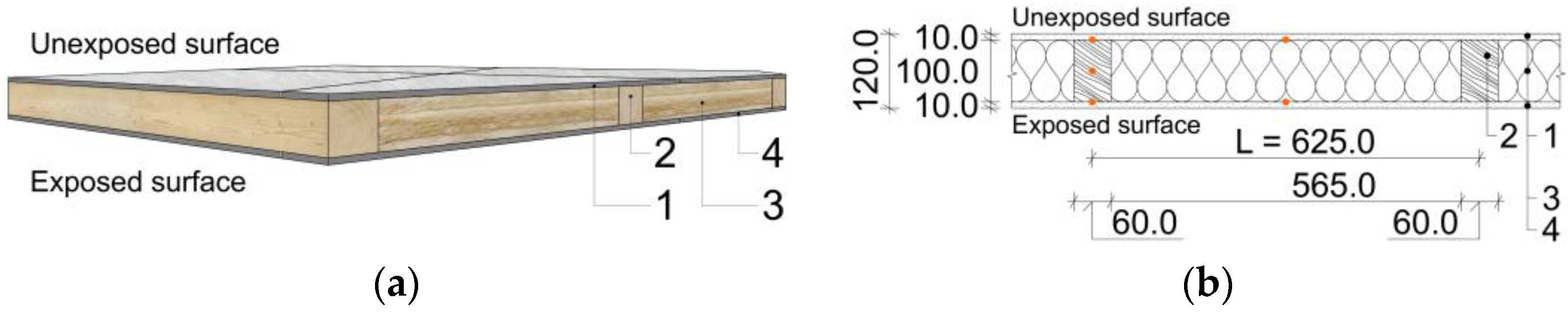
The specimen presents a typical structure of the inner wall of timber buildings. The schematic 3D section (a) and cross-section (b) with the dimensions of the materials and elements of the tested structure can be seen in
Figure 1.
The dimensions of the structure were adapted to the dimensions of the experimental testing equipment. The height and width of the wall were reduced from the original dimensions of 3 m × 3 m to the reduced dimensions of 1.3 m × 2.3 m. The sample height ratio was 1:0.76, and the sample width ratio was 1:0.43, compared to the procedure according to the standards. The cross-sectional dimensions of the wooden elements were maintained at the original values, as well as the sample thickness of 0.12 m.
The frame was built from spruce timber (average density 450 kg∙m
−3) studs with cross-sectional dimensions of 60 mm × 100 mm (layer no. 2). The fire reaction class of the timber studs is classified as D-s2, d0 [
23]. The insulation was from glass-based mineral wool (A1) between the wooden frame with the same thickness as the studs (layer no. 3). The structure was covered by the cement fibre board cladding (layers no. 1 and 4). The total dimensions of the tested specimen were 1.3 m × 2.3 m × 0.12 m (width × length × thickness). The structure can be classified as the DP2 structural part, according to Czech standards [
24]. This classification is analogous to the European system with K classes for the fire protection ability of coverings. The K classes are divided into two types, according to the properties of the substrate behind the protective material. A K
2 class is usually assessed for the protection of wood. The K classes allow the classification of claddings from combustible materials, which can also protect the structure from the effects of fire [
25]. The DP2 classification can also be compared to the principle of fully encapsulated structures. The structure can be classified as a DP3 structural part after the failure of the lower exposed layer of the cement fibre boards. This complies with the principle of partial encapsulation, where the wood surfaces are protected from rapid flame spread, but it will not prevent the charring or ignition of the underlying timber in the later fire stage [
14].
The specimen was conditioned at ambient test hall conditions, with a relative air humidity (RH) of (50 ± 5)% and temperature of (23 ± 5) °C.
3. Methods
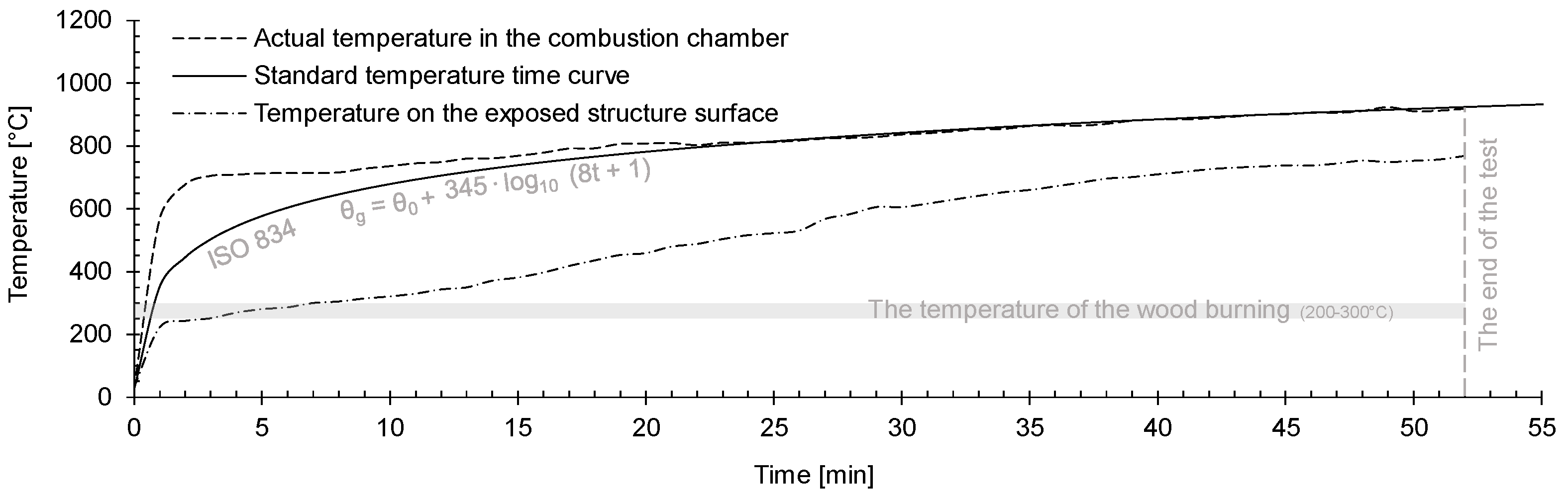
Exposure to high temperatures was applied by means of fire in the testing furnace. The fire source was a pair of burners that used gas as fuel, mixed with oxygen, which is necessary for combustion. The burners were automatically controlled so that the rate of gas release corresponded to the fire development in accordance with the logarithmic standard time–temperature curve [
26], which is typical for indoor fires. The course of this curve is given by the following Equation (1):
where
θg is the average temperature in the combustion chamber [°C],
θ0 is the initial furnace temperature [°C], and
t is the time of the test [min].
The temperature was a bit higher in the first few minutes of the test because of the higher burner performance. Previous research points to the fact that a thermal exposure slightly higher than the standard time–temperature curve has less effect on the fire resistance than a lower thermal exposure [
27]. The lower thermal exposure than the standard curve provides better fire resistance values, which can significantly affect the final evaluation of the medium-scale test. Based on these facts, the temperature loading took place according to the standard time–temperature curve during the experimental medium-scale FR test. The sample with the original thickness (1:1) was, therefore, tested under the standard thermal loading.
The temperature courses in the combustion chamber are shown in the chart in
Figure 2.
The temperature was also measured on the exposed surface of the specimen. The temperature course from the thermocouple shows that the measured values were lower than the actual temperature in the furnace. The temperatures on the heated surface can be affected by uneven temperature distribution in the combustion chamber. The temperature gradient under the ambient test hall conditions and the higher thermal conductivity of the cement fibre boards (0.35 W∙m−1∙K−1), compared to the other lining materials, such as gypsum plasterboards, can also affect the exposed surface temperature.
The standard FR tests are performed on specimens with dimensions 3 m × 3 m, according to the test procedure for non-load-bearing walls. The structure was tested with reduced dimensions as a medium-scale FR test. The internal dimensions of the testing equipment (combustion chamber) were 2 m × 1 m × 1 m. The furnace allows temperature loading up to a maximum value of 1100 °C. The required conditions were monitored and met during the experimental test. The specimen was placed on the upper part of the testing equipment in a horizontal position, with an overlap of 150 mm on each side. The sample was exposed to fire from the bottom, so the area exposed to fire was 2 m × 1 m. The testing method is based on the results of previous research [
28,
29]. The temperature distribution is slightly higher in the middle-scale combustion chambers than in the standard testing equipment [
30]. The results from the other previous study [
30] showed that the heat exposure to a test specimen in a furnace oriented horizontally was slightly severer (4%) than in a furnace oriented vertically, and the heat exposure in the intermediate-scale furnace was approximately 15% higher than in the full-scale equipment. The effect of the orientation of the tested specimen (vertical vs. horizontal) was also investigated in the previous research [
28,
29]. The results were consistent with the data and conclusions presented in similar researches [
30].
The specimen was loaded by thermal stress during the test. The heat received by the test specimen was mainly by radiation and convection. The convective part is not as significant as the radiative part. The convective heat occurs by natural convection in full-scale combustion chambers and by forced convection in smaller-size furnaces. The pressure and the thermal distribution in the furnace were controlled by a ventilation system of the equipment. Heat transfer by forced convection is greater than by natural convection [
30,
31].
The temperature courses were measured in the composition of the structure between the layers and on the unexposed surface structure. The unexposed surface temperatures were measured using attached thermometers at positions S1, S2, and S3. The measured points can be seen in
Figure 3. The final evaluation of the structure was based on the measured temperatures during the test. The temperatures allow the assessment of the limited state (LS) of thermal insulation ability (I). The criteria of this LS (I) were assessed based on the temperature increases. The average temperature increase on the unexposed face is limited to 140 °C above the initial mean temperature, and the maximum temperature increase at any point is limited to 180 °C above the initial mean temperature [
32].
The temperature courses inside the structure were measured by thermocouples at the positions of the studs and between them. The thermocouples were connected to a pair of measurement modules, and the data were continuously recorded. The positions of the thermocouples inside the specimen are shown in
Figure 3. The temperature profiles are described in
Table 1. The thermocouples were built into the structure during sample preparation.
The start of the charring of the timber elements in the structure was determined from the temperature records. The critical temperature of 300 °C was measured on the exposed surface at the position of the studs [
9]. The temperature course was also measured in the centre of the timber stud at half the height (TP 9). This thermocouple controlled the stud’s wood core condition during the thermal loading.
The LS of integrity (E) was evaluated according to the condition of the unexposed surface structure during the test. The assessment of integrity was made based on visual inspection. The visible cracks were assessed according to their thickness using gap gauges (6 mm and 25 mm) [
32]. These measurements and evaluations are described in the results.
The specimen before the start of the test and the test equipment can be seen in
Figure 4.
4. Results
The thermal loading of the tested structure was performed for the test duration of 52 min. The temperatures measured on both surfaces inside of the structure can be seen in the figures below (
Figure 5 and
Figure 6). The temperatures between the exposed cement fibre board and the thermal insulation (glass-based mineral wool) are shown by the courses TP1 and TP2 in the chart in
Figure 5. These temperature profiles show gradual increases in temperature throughout the test. The limit of 300 °C was exceeded after the 15th minute (TP1) and 22nd minute (TP2). The smooth rising course of the temperature curves may indicate the integrity of the boards.
Data from the thermocouples placed at the positions under the timber elements are shown by the temperature profiles TP3, TP4, TP10, and TP11. TP10 and TP11 show higher temperatures at the position of the glued board joints. The chart shows an obvious failure of the cement fibre boards between the 25th–30th minute (rapid rise in temperatures). The evaluation of the structure type can be based on these values.
The specimen’s temperature profiles in the upper part (unexposed surface) can be seen in
Figure 6. The low values indicate the thermal insulating properties of the structure.
The temperature rises of TP5 and TP6 show a failure of the thermal insulation layers between the timber elements of the frame. TP7, TP8, and TP12 point to the thermal insulation properties of wood. These temperature profiles were measured on the unexposed surfaces of the timber elements. The measured values reached temperatures around 130 °C at the end of the test. This shows that the wood mass on this side of the structure was not damaged by the fire. The last thermocouple was placed in the centre of the timber stud at half the height. The TP9 from this thermocouple shows an approximate temperature distribution along the height of the timber element.
The unexposed boards (upper surface) were broken by cracks. The progress of the defect of the upper cement fibre boards can be seen in
Figure 7. The first crack formed at the position between the timber studs around the 42nd minute of the test—
Figure 7a. The size of this crack was about 2 mm in the 47th minute after the start—
Figure 7b. The other measuring of the crack was according to the gap gauges based on the EN standards. The 6 mm diameter gap gauge can penetrate a through gap, such that the end of the gauge projects into the furnace—
Figure 7c. The gauge cannot be moved in the gap for a distance of at least 150 mm, so this requirement for the LS (E) violation was not exceeded. This LS (E) was exceeded in the 52nd minute because of the penetration of a 25 mm gauge through the specimen—
Figure 7d. This over-limit crack formed at the position of the thermocouple with TP5.
The insulating properties in terms of the FR can be assessed based on the surface temperatures. The temperatures were measured at three points (S1, S2, and S3) of the unheated surface in five-minute intervals. The temperatures and their average values are shown in
Table 2.
The temperature courses from the data in
Table 2 are shown in
Figure 8. The highest values were measured at the position of surface point S1 (see
Figure 3). The limit value (average increase of Δt = 140 °C) was exceeded after the 47th minute. The limit value of the maximum increase of Δt = 180 °C was exceeded in point S1 also around the 48th minute. Exceeding the limit values can be seen in the figure below.
The maximum temperature was 141.3 °C at point S1 at the 45th minute. The maximum increase of the temperature was Δt = 116.5 °C, according to the value of the initial surface temperature. The average temperature was 118.6 °C at the 45th minute, so the average increase of the temperature was Δt = 93.8 °C.
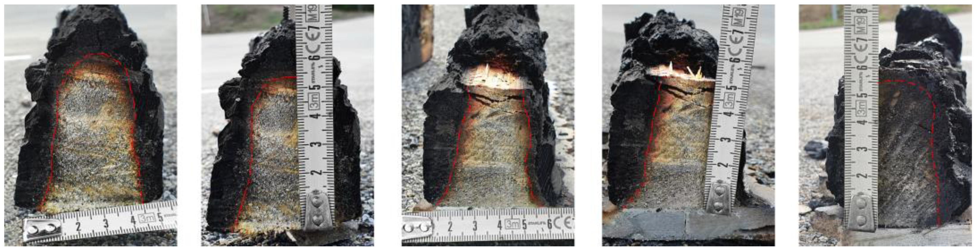
The load-bearing capacity of structures must be tested under the loading on the samples. The loading must comply with the standard requirements throughout the test. The experimental test equipment does not allow the loading during the test due to the properties of the equipment. The load-bearing capacity requirements were, therefore, not monitored. The condition of the timber elements was analysed after the end of the test. The studs were cut in the most damaged positions, and all samples were measured and registered. The data were then processed in the CAD software for further analysis. The timber studs were exposed to fire from one side in the first half of the experiment. This is given by the encapsulation in the non-combustible cement fibre boards. Charring of the timber occurred only on the edges in contact with the fire-exposed boards, so there was a less rapid reduction in the wooden mass and strength [
33,
34]. After the exposed boards were completely damaged, the insulation between the timber studs loosened and fell off. The timber elements were exposed from three sides from this time, and the reduction in the stud’s dimensions was faster. The cross-sectional area after the 52 min test can be seen in
Figure 9b and
Figure 10.
Figure 9a presents the average temperatures from the thermocouples placed at the positions of the exposed and unexposed timber surface. TP9 shows the temperature course in the centre of the timber stud at half the height. It can be assumed that the wood mass in the middle of the element was only minimally affected by the temperature. The maximum temperature rise was Δt = 185 °C at this position at the end of the test (52nd minute) and Δt = 159 °C in the 45th minute, so the wood burning limit was not exceeded.
The carbon charred layer can be seen in the cross-sections of the timber studs at the end of the test—
Figure 10.
The conditions of the specimen after the test can be seen in
Figure 11 and
Figure 12.
Figure 11 shows the structural damage and the first oversized cracks of the unexposed cement fibre board surface.
5. Discussion
The results of the experimental FR test allow the final evaluation of the structure. The fire resistance limit states (LSs) can be evaluated based on the limitations in the standards.
The lower layers of the non-flammable cladding were broken around the 20th–25th minute. This was based on the sharp temperature rise at this time, as can be seen in
Figure 5. The specimen can be evaluated as a DP2 structural part (the combustible timber elements covered by the non-combustible cement fibre board layer) for 15 min [
24], and after this time, as a DP3 (unprotected combustible material) because of the crack failure of the lower boards.
The LS of insulation ability (I) can be assessed according to the unexposed surface temperatures. The structure complied with the requirements for the LS (I) for 45 min [
24]. The maximum temperature increase was 116.5 °C (see
Figure 8), so the final assessment is Δt = 116.5 °C ≤ 180 °C. The average temperature increase was 93.8 °C (see
Figure 8), so the final assessment is Δt = 93.8 °C ≤ 140 °C. Both requirements were met in a classification time of 45 min.
The LS of integrity (E) can be assessed according to the condition of the unexposed surface. This LS was exceeded in the 52nd minute because of the excessive crack damage. This LS can be also classified for 45 min [
24].
The LS of radiation–heat flux density (W) was not measured. The maximum measured value of the radiation must be lower than 15 kW∙m−2. Even so, an element that satisfies the thermal insulation criterion is also deemed to satisfy the W requirement for the same period.
The specimen was not loaded by forces during the test due to the limits of the testing equipment. The residual undamaged area of the wood mass was about 32% of the original value of the cross-sectional area.
The final fire resistance of the specimen can be classified as EI 15 DP2 and EI 45 DP3 [
24].
6. Conclusions
This study was focused on the experimental fire resistance testing of the non-load-bearing timber structure covered by cement fibre boards. The test was performed using equipment enabling thermal loading and simulating the conditions during the fire. The specimen was exposed to high temperatures, according to the standard logarithmic time–temperature curve. The structure was tested with reduced dimensions as a medium-scale FR test.
The experimental test showed that the failure of the structure was based on the insulation failure criterion, which was exceeded first. The limit state of the integrity was exceeded in the 52nd minute, but the first insignificant cracks were observed around the 42nd minute, with a surface temperature of 110 °C. Although the structure’s load-bearing capacity was not monitored, the measured temperature profiles (TPs) on the surfaces and inside of the timber studs and the residual cross-sectional area of the timber studs indicate the load-bearing ability of the specimen during and after the test.
It is obvious that cement fibre boards contribute to the higher fire resistance of structures with combustible load-bearing elements and do not increase the intensity of the fire. The structure complied with the requirements for the DP2 structure part. The final fire resistance of the sample was in the expected values, compared to the previous test [
35]. The evaluations EI 15 DP2 and EI 45 DP3 correspond to the similar timber structures tested with claddings made of gypsum fibre boards. Based on previous studies [
27,
28,
29,
35], it can be assumed that the final fire resistance of the structure is slightly higher compared to the standard course of the test. This fact is given by the influence of the tested sample position, the uneven temperature distribution in the experimental combustion chamber, and the change in sample scale. To obtain a valid fire classification certificate for the structural fire resistance, it is always necessary to comply with the conditions specified in the test standards. Even so, this experimental method of medium-scale testing provides acceptable data for a preliminary fire resistance evaluation of new structures with much lower financial expenses.
This study has shown that cement fibre boards provide sufficient fire protection for timber elements. The fire resistance properties of these boards are comparable with other materials used in systems of dry building constructions.
Author Contributions
Conceptualization, K.Š. and T.Ž.; methodology, K.Š. and T.Ž.; formal analysis, T.Ž.; data curation, T.Ž.; writing—original draft preparation, T.Ž. and D.P.; supervision, K.Š.; project administration, T.Ž.; funding acquisition, K.Š. All authors have read and agreed to the published version of the manuscript.
Funding
This research was funded by the research project FAST-S-22-8000 of the Faculty of Civil Engineering at Brno University of Technology, Brno, Czech Republic.
Data Availability Statement
The raw data supporting the conclusions of this article are available from the authors on reasonable request.
Acknowledgments
This research was supported by the Faculty of Civil Engineering at Brno University of Technology in Brno, Czech Republic, using the equipment of the AdMaS Science and Research Center (Advanced Materials, Structures and Technologies).
Conflicts of Interest
The authors declare no conflict of interest. The funders had no role in the design of the study; in the collection, analyses, or interpretation of data; in the writing of the manuscript; or in the decision to publish the results.
References
- Östman, B. National fire regulations for the use of wood in buildings—Worldwide review 2020. Wood Mater. Sci. Eng. 2021, 17, 4. [Google Scholar] [CrossRef]
- EN 1995-1-2:2004; Eurocode 5: Design of Timber Structures—Part 1-1: General—Structural Fire Design. Eur. Comm. Stand. (CEN): Brussels, Belgium, 2004.
- Dârmon, R. Separating function of timber floor and wall assemblies. IOP Conf. Ser. Mater. Sci. Eng. 2022, 1242, 012012. [Google Scholar] [CrossRef]
- Piloto, P.A.G.; Rodríguez-del-Río, S.; Vergara, D. Fire analysis of timber-framed walls lined with gypsum. Materials 2022, 15, 741. [Google Scholar] [CrossRef]
- Chaturvedi, S.; Vedrtnam, A.; Youssef, M.A.; Palou, M.T.; Barluenga, G.; Kalauni, K. Fire-resistance testing procedures for construction elements—A Review. Fire 2022, 6, 5. [Google Scholar] [CrossRef]
- Gan, W.; Chen, C.; Wang, Z.; Song, J.; Kuang, Y.; He, S.; Mi, R.; Sunderland, P.B.; Hu, L. Dense, self-formed char layer enables a fire-retardant wood structural material. Adv. Funct. Mater. 2019, 29, 9. [Google Scholar] [CrossRef]
- Perković, N.; Rajčić, V. Mechanical and fire performance of Innovative hollow glue-laminated timber beams. Polymers 2022, 14, 3381. [Google Scholar] [CrossRef]
- Green, D.W.; Evans, J.W.; Logan, J.D.; Nelson, W.J. Adjusting modulus of elasticity of lumber for changes in temperature. For. Prod. J. 1999, 49, 82–94. Available online: https://www.proquest.com/scholarly-journals/adjusting-modulus-elasticity-lumber-changes/docview/214623289/se-2 (accessed on 9 September 2022).
- Lineham, S.A.; Thomson, D.; Bartlett, A.I.; Bisby, L.; Hadden, R.M. Structural response of fire-exposed cross-laminated timber beams under sustained loads. Fire Saf. J. 2016, 85, 23–34. [Google Scholar] [CrossRef]
- Tiso, M.; Just, A. Design criteria for insulation materials applied in timber frame assemblies. J. Struct. Fire Eng. 2017, 9, 252–263. [Google Scholar] [CrossRef]
- White, R.H.; Dietenberger, M. Wood Products: Thermal Degradation and Fire. Encycl. Mater. Sci. Technol. 2001, 9712–9716. [Google Scholar] [CrossRef]
- Richter, F.; Kotsovinos, P.; Rackauskaite, E.; Rein, G. Thermal response of timber slabs exposed to travelling fires and traditional design fires. Fire Technol. 2021, 57, 393–414. [Google Scholar] [CrossRef]
- Osvald, A.; Štefko, J. Modelový Požiar Dvojpodlažnej Drevostavby; Šmíra-Print: Ostrava, Czech Republic, 2013; ISBN 978-80-87427-85-9. [Google Scholar]
- Buchanan, A.; Östman, B. (Eds.) Fire Safe Use of Wood in Buildings: Global Design Guide, 1st ed.; CRC Press: Boca Raton, FL, USA, 2022; pp. 196–200. ISBN 9781003190318. [Google Scholar] [CrossRef]
- Buchanan, A. Fire resistance of multistorey timber buildings. Fire Sci. Technol. 2017, 9–16. [Google Scholar] [CrossRef]
- Xu, H.; Pope, I.; Gupta, V.; Cadena, J.; Carrascal, J.; Lange, D.; McLaggan, M.S.; Mendez, J.; Osorio, A.; Solarte, A.; et al. Large-scale compartment fires to develop a self-extinction design framework for mass timber—Part 1: Literature review and methodology. Fire Saf. J. 2022, 128, 103523. [Google Scholar] [CrossRef]
- Gnanachelvam, S.; Ariyanayagam, A.; Mahendran, M. Fire resistance of LSF wall systems lined with different wallboards including bio-PCM mat. J. Build. Eng. 2020, 32, 101628. [Google Scholar] [CrossRef]
- Yue, K.; Liang, B.; Liu, J.; Li, M.; Pu, Y.; Lu, W.; Han, Z.; Li, Z. Fire resistance of light wood frame walls sheathed with innovative gypsum-particle composite: Experimental investigations. J. Build. Eng. 2022, 45, 103576. [Google Scholar] [CrossRef]
- Magarabooshanam, H.; Ariyanayagam, A.; Mahendran, M. Fire resistance of non-load bearing LSF walls with varying cavity depth. Thin-Walled Struct. 2020, 150, 106675. [Google Scholar] [CrossRef]
- Schabowicz, K.; Sulik, P.; Gorzelańczyk, T.; Zawiślak, Ł. Assessment of the destruction of a fibre cement board subjected to fire in a large-scale study. Materials 2022, 15, 2929. [Google Scholar] [CrossRef]
- Schabowicz, K.; Gorzelańczyk, T.; Szymków, M. Identification of the degree of degradation of fibre-cement boards exposed to fire by means of the acoustic emission method and artificial neural networks. Materials 2019, 12, 17. [Google Scholar] [CrossRef]
- Babrauskas, V. Charring rate of wood as a tool for fire investigations. Fire Saf. J. 2005, 40, 528–554. [Google Scholar] [CrossRef]
- Östman, B.; Mikkola, E. European classes for the reaction to fire performance of wood products. Holz Als Roh Und Werkst. 2006, 64, 327–337. [Google Scholar] [CrossRef]
- ČSN 73 0810; Požární Bezpečnost Staveb—Společná Ustanovení. ÚNMZ: Praha, Czech Republic, 2016.
- Östman, B.; Boström, L. Fire protection ability of wood coverings. Fire Technol. 2015, 51, 1475–1493. [Google Scholar] [CrossRef]
- ISO 834; Fire Resistance Tests-Elements of Building Constructions. International Standard Organisation (ISO): London, UK, 1975.
- Norén, J.; Östman, B. Contribution to fire resistance from building panels. Fire Saf. Sci. Proc. First Int. Symp. Hemisph. 2011, 1, 325–335. [Google Scholar] [CrossRef]
- Žajdlík, T.; Šuhajda, K. Experimental fire resistance test of timber structure. Juniorstav 2022, 2021, 55–59. [Google Scholar] [CrossRef]
- Žajdlík, T.; Šuhajda, K. Comparison of fire resistance testing methods for structures with timber elements. Adv. Sci. Technol. 2021, 109, 73–85. [Google Scholar] [CrossRef]
- Sultan, M.A.; Benichou, N.; Min, B.Y. Heat exposure in fire resistance furnaces: Full-scale vs intermediate-scale. In Proceedings of the 2003 Fire and Materials International Conference, San Francisco, CA, USA, 27–29 January 2003; pp. 45–53. [Google Scholar]
- Sultan, M.A.; Harmathy, T.Z.; Mehaffey, J.R. Heat transmission in fire test furnaces. Fire Mater. 1986, 10, 47–55. [Google Scholar] [CrossRef]
- EN 1363-1:2020; Fire Resistance Tests. European Committee for Standardization: Brussels, Belgium, 2020.
- Buchanan, A.H. Fire performance of timber construction. Prog. Struct. Eng. Mater. 2000, 2, 278–289. [Google Scholar] [CrossRef]
- König, J.; Norén, J.; Olesen, F.; Hansen, F. Timber Frame Assemblies Exposed to Standard and Parametric Fires: Part 1, Fire Tests; Traetek: Stockholm, Sweden, 1997; ISSN 1102-1071. [Google Scholar]
- Žajdlík, T.; Šuhajda, K. Experimental testing results of a timber structure’s fire resistance in a combustion chamber. Key Eng. Mater. 2022, 932, 225–230. [Google Scholar] [CrossRef]
| Disclaimer/Publisher’s Note: The statements, opinions and data contained in all publications are solely those of the individual author(s) and contributor(s) and not of MDPI and/or the editor(s). MDPI and/or the editor(s) disclaim responsibility for any injury to people or property resulting from any ideas, methods, instructions or products referred to in the content. |
© 2023 by the authors. Licensee MDPI, Basel, Switzerland. This article is an open access article distributed under the terms and conditions of the Creative Commons Attribution (CC BY) license (https://creativecommons.org/licenses/by/4.0/).


