Article

Flexural Performance of a Novel Steel Cold-Formed Beam–PSSDB Slab Composite System Filled with Concrete Material

by
Mohammed Chyad Liejy
1,2,
Ahmed W. Al Zand
1,*,
Azrul A. Mutalib
1,
Mustafa Farooq Alghaaeb
1,3,
Ali A. Abdulhameed
4,
Alyaa A. Al-Attar
5,
Wadhah M. Tawfeeq
6 and
Salam J. Hilo
7
1
Department of Civil Engineering, Universiti Kebangsaan Malaysia (UKM), Bangi 43600, Malaysia
2
Al-Hawija Technical Institute, Northern Technical University, Kirkuk 36001, Iraq
3
Engineering Affairs, Ministry of Culture, Baghdad 13032, Iraq
4
Department of Reconstruction and Projects, University of Baghdad, Baghdad 10071, Iraq
5
Northern Technical University, Mosul 41002, Iraq
6
Faculty of Engineering, Sohar University, Sohar 311, Oman
7
Civil Engineering Department, University of Technology, Baghdad 10066, Iraq
*
Author to whom correspondence should be addressed.
Buildings 2023, 13(2), 432; https://doi.org/10.3390/buildings13020432
Submission received: 6 January 2023 / Revised: 27 January 2023 / Accepted: 31 January 2023 / Published: 3 February 2023
(This article belongs to the Special Issue Non-linear Behavior and Design of Steel Structures)

Abstract

:
In this study, the flexural performance of a new composite beam–slab system filled with concrete material was investigated, where this system was mainly prepared from lightweight cold-formed steel sections of a beam and a deck slab for carrying heavy floor loads as another concept of a conventional composite system with a lower cost impact. For this purpose, seven samples of a profile steel sheet–dry board deck slab (PSSDB/PDS) carried by a steel cold-formed C-purlins beam (CB) were prepared and named “composite CBPDS specimen”, which were tested under a static bending load. Specifically, the effects of the profile steel sheet (PSS) direction (parallel or perpendicular to the span of the specimen) using different C-purlins configurations (double sections connected face-to-face, double separate sections, and a single section) were investigated. The research discussed the specimens’ failure modes, flexural behavior, bending capacity, bending strain relationships, and energy absorption index of specimens. Generally, the CBPDS specimens with the PSS slab placed in a parallel direction achieved approximately a 13–40% higher bending capacity compared with the corresponding specimens with a perpendicular PSS direction (depending on the configuration of the beam). Fabricating the beam of the CBPDS specimen with double C-purlins (face-to-face) led to more effective concrete confinement behavior compared with the double separate C-purlins beam. The related specimen recorded a 10% higher bending capacity. Finally, the suggested composite CBPDS system exhibited a sufficient energy absorption capability of the static bending load because it demonstrated high strength and high ductility.

1. Introduction

The construction industry continuously attempts to enhance and develop modern composite structural elements that are more economical, strong, environmentally friendly, and easily fabricated than conventional elements. Over the last three decades, several studies have specifically investigated the performance of cold-formed profile steel sheets (PSS) covered with dry board (DB) sheets in a lightweight composite slab system [1,2,3,4], which is usually known as a PSSDB or PDS slab system. An excellent bond interaction between parts of the PSS and the DB has been achieved using self-tapping screws, which have been sufficiently investigated based on several direct push-out tests [5,6,7].
Recently, several studies have investigated the structural performance of the PSS slab system [8,9,10,11] and wall system [12,13,14] when filled with concrete materials. Filling these structural elements with concrete material leads to preventing and/or delaying the local buckling that occurs for the PSS part under high compression stress, which in return leads to improved strength in the composite system. For example, the flexural strength, ductility, and stiffness of the two-way PSSDB slab system were significantly improved when filled with lightweight concrete material [8]. In the case of a one-way slab system, Jaffer et al. (2015 and 2016) investigated the effects of filling the PSSDB with geopolymer and normal concrete materials [9,11]. However, even after filling with concrete materials, the PSSDB cross-section is considered to be a slender section (small depth), which is applicable for limited spanning length due to the high deflection failure scenario. Thus, to carry high flooring loads and place for relatively longer spans, this concrete-filled PSSDB deck slab system needs to be connected/combined with steel beam [15], much similar to the conventional composite steel beam–concrete deck slab system [16,17], as illustrated in Figure 1. However, the challenge emerges when it is required to provide the shear studs for connecting the top flange of steel I-beam with this concrete-filled PSSDB deck slab since it has a slender cross-section. Thus, it could be necessary to use an alternative method of connection and/or use another type of beam to carry this type of slab (concrete-filled PSSDB).
Over the past two decades, researchers are continuously investigating the flexural performance of a new composite steel–concrete beam system which is usually known as a concrete-filled steel tube (CFST) beam. This system was suggested as another type of composite steel beam–concrete system that can achieve several advantages related to strength, ductility, and cost impact [18,19,20]. These studies used different analysis methods (experimental and numerical methods) and under varied loading scenarios (static, impact, and cyclic) [21,22,23,24,25,26,27,28], as well as the behavior of a combination of multi-cells of CFST beams [29,30]. In addition, adopting the cold-formed steel tube sections in the CFST beams system was suggested since it can be easily fabricated with any shape and thickness that is required for the design requirements [31,32,33,34,35]. Recently, the galvanized C-purlin steel sections have been adopted in the CFST beam system due to the advantages of the lightweight and availability in the local market. For example, Al Zand et al. (2022) experimentally and numerically investigated the flexural performance of using a single C-purlin section filled with normal and recycled concrete materials [36]. Using double sections of C-purlins (face-to-face connection) to fabricate the steel tube in the CFST beam system led to an improvement in the concrete confinement behavior [37,38]. Additionally, some studies adopted the CFST beam in the composite truss–concrete deck slab system [20,39,40,41] and beam–concrete deck slab system [42,43].
The flexural performance of PSSDB slabs and cold-formed CFST beam systems has been independently investigated, whereas the combination of these two composite members to provide a new composite beam–slab system has not yet been investigated. This is the main research gap in the literature. A novel composite beam–slab system has been suggested as an alternative solution to conventional steel beam–concrete deck slab systems, which could be attributed to various reasons and different purposes (such as the cost impact, availability of raw materials, ductility, lighter weight of steel parts, and easy/fast fabrication). Therefore, the main objective of this research was to experimentally investigate the influence of using a cold-formed steel C-Purlin beam (CB) that was fully connected to a PSSDB deck slab where both parts were filled with concrete material to develop a novel composite CFST beam–PSSDB slab system, named the composite CBPDS specimen. We particularly investigated the effects of using single/double C-sections as the main girder as well as the parallel/perpendicular direction of the PSS deck slab on the flexural performance of the suggested CBPDS system. The failure modes, flexural behavior, bending/carrying capacity, bending strain relationships, and energy absorption index established from the tests were extensively discussed.

2. Experimental Approach

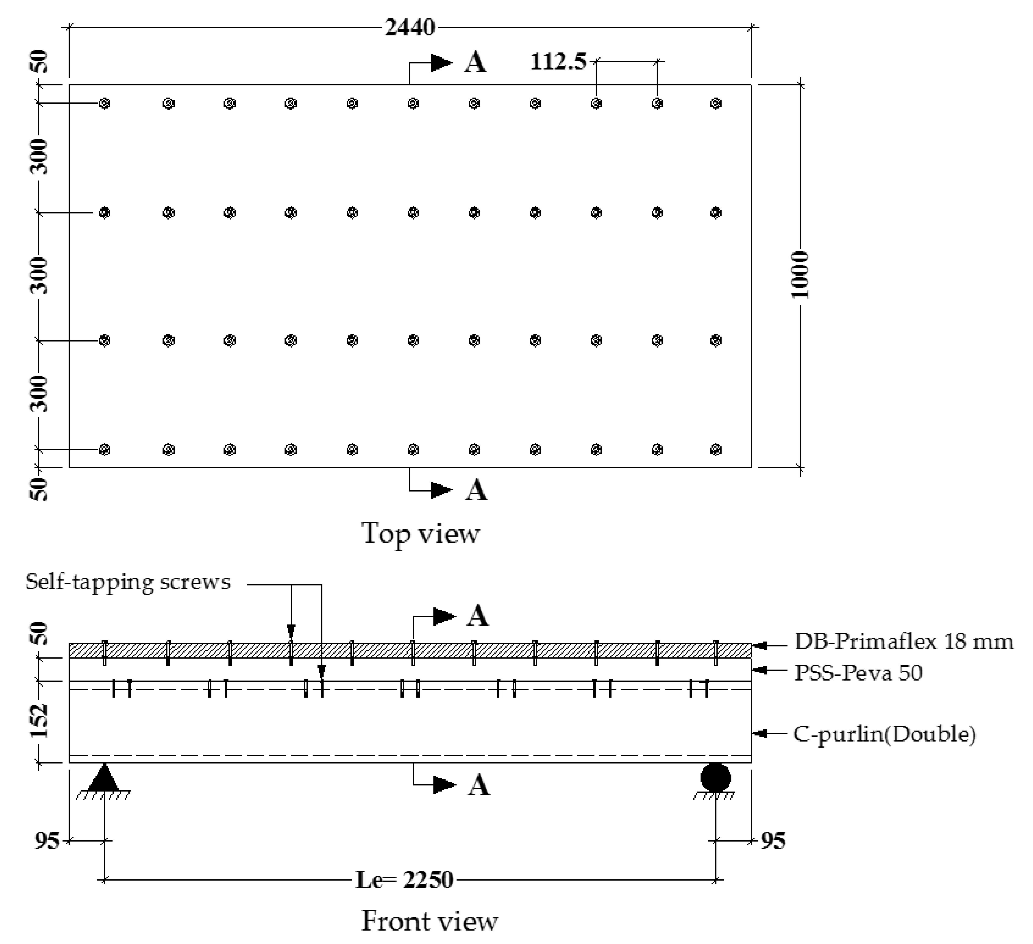
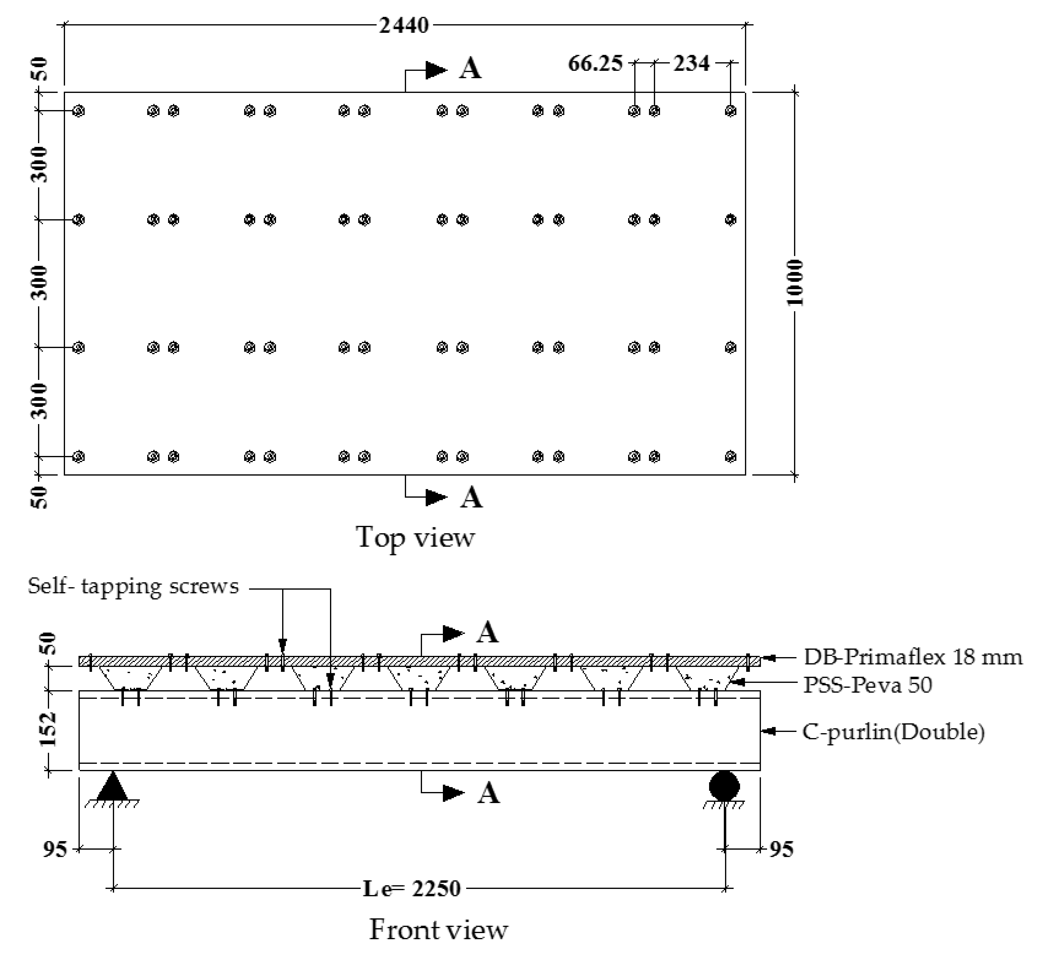
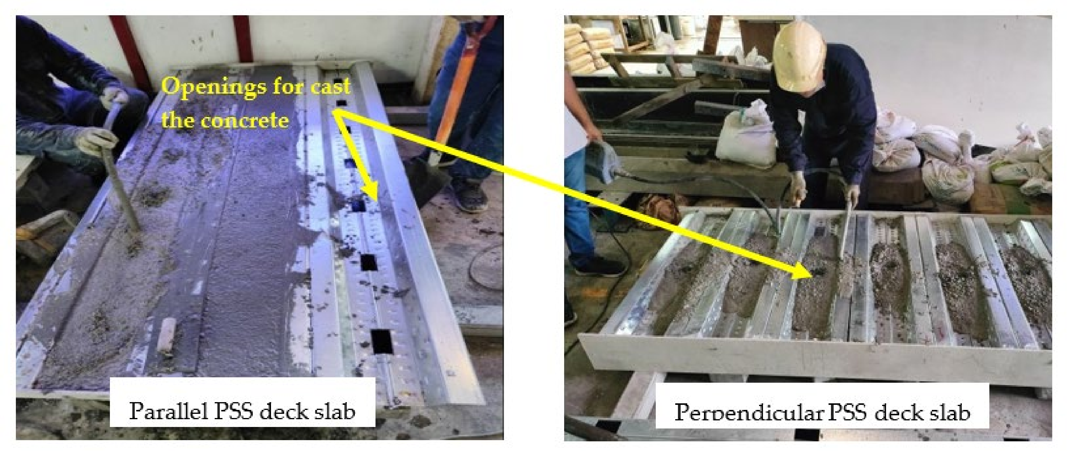
2.1. Specimens Preparation

Seven (7) composite CBPDS specimens are prepared in this research that are mainly fabricated from cold-formed C-purlins beam (CB) and profile steel sheet-dry board (PSSB/PDS) deck slab, in which both parts of beam and slab are filled with concrete material. Figure 2 depicts the specimens’ designation ID, which describes the adopted cold-formed beam’s configuration (double face-to-face connection, double separate, or single C-purlin section) and the direction of PSS’s ribs (parallel/perpendicular). For all specimens, each C-purlin section is fabricated with 152 mm depth, 64 mm flange width, 16 mm lips length, and 2 mm thickness. The PSS section is fabricated with 1000 mm width, 50 mm depth, and 1 mm thickness, which are named Peva 50 (in the local market), which is covered by a dry board (DB) cement sheet (type Primaflex) with 1000 mm width and 18 mm thickness. For easy and fast preparation of the suggested composite CBPDS system, all parts (DB with PSS and PSS with CB) are connected by self-tapping steel screws. The overall length of these specimens is equal to 2440 mm, and the effective length are equal is to 2250 mm. Figure 3 and Figure 4 present the details of CBPDS specimens prepared with a PSS deck slab placed parallel to their beam’s direction, while Figure 5 and Figure 6 present the CBPDS specimens with PSS deck slab in a perpendicular direction. The details of specimens are listed in Table 1, including the additional two control specimens of beam CB specimen and slab PDS.
Generally, most of the existing research has placed hollow steel tube members vertically to pour the concrete inside; these were then placed horizontally after the concrete had set [38,44,45]. This concrete pouring scenario is considered to be a challenge at a construction site when CFST beams must be prepared. Therefore, in this research, a new technique was used to cast the concrete inside the C-purlins beam and the PSS slab together and at the same time, specifically when the CBPDS specimen was placed horizontally (similar to an actual site condition), as shown in Figure 7. To achieve this, several openings (40 mm × 80 mm × 340 mm c/c) were provided, specifically at the interaction surface between the top flange of the C-purlins and the bottom flange of the PSS parts. These openings are easy to cut on-site using an ordinary electrical cutter device due to the small thickness of these two parts (C-purlins and PSS sections). After the concrete set, the concrete portions located at these openings were expected to behave as shear connectors to sufficiently connect the slab part with the beam part in the suggested CBPDS composite system. The PSS slab was also connected to the C-purlins beam using self-tapping screws of 30 mm length; these were provided at several locations, where the extra length of these screws was used as an embedded connector to nail the concrete core inside the C-purlins section (see Figure 4 as an example), similar to the scenario previously confirmed in [36]. The opened sides of the C-purlins and PSS slab were temporarily closed by pieces of wood/dry board during the casting time of the concrete; these were removed after 24 h. An electrical vibrator was used during the concrete casting time to ensure that there were no air voids inside the casting concrete. After the concrete was initially set, the DB sheets were mechanically fixed to the PSS slab using the self-tapping screws.

2.2. Material Properties

A galvanized cold-formed steel section (C-purlins) was used to fabricate the composite beam in this study. A profile steel sheet (PSS) (Peva 50) was chosen for the composite slab since it has a large rib width and feature, which makes this section sufficient for filling the section with concrete material [9,11]. The physical properties of these steel sections (C-purlin and PSS) are obtained from direct tensile tests of three coupons prepared as per the ASTM-E8/E8M-2009 standard. A cement dry board (DB) (Primaflex) was used in this composite system. Table 2 resent the properties of these materials.
Self-tapping screws were used to connect the parts of the suggested composite CBPDS system. Two types of screws were used; the DS-FH 432 screw, which was used to connect the PSS slab to the C-purlin beam, and the DS-HW 640 screw, which was used to connect the DB sheets to the PSS slab [8,9,10]. The properties are shown in Table 2.
Normal concrete was used as the infill material for all CBPDS specimens. The concrete mixture was prepared from 395 kg/m3 Portland cement (the local type in Malaysia), 700 kg/m3 washed sand (fine aggregate with a density of 1570 kg/m3), and 1115 kg/m3 crushed limestone coarse aggregates (density of 1498 kg/m3) with a maximum particle size of 10 mm. These were mixed with a 0.48 water/cement ratio. A superplasticizer (RF 611 B/N 211705; 1.42 L/m3) was used as an additive material to improve the workability of the concrete mixture. The concrete samples were cast and cured to evaluate the compressive strength of the concrete as per the requirements of BS1881-Part116 1983.

2.3. Test Setup

Figure 8 shows the test setup of the investigated CBPDS specimens under two-point static loads. Three devices of the linear variable differential transformer (LVDT) were placed underneath the specimens to measure the deflection at different locations (center and quarter-span of the specimen). Strain gauges (SG) were horizontally distributed at the mid-span of the specimens to record the longitudinal strains at the surfaces of the C-purlins, PSS, and DB during the test. These SGs were numbered SG1 at the top surface of the DB (maximum compression zone), SG2 at the top flange of the PSS, SG3 at the top flange of the C-purlin (connection level with the PSS deck slab), SG4 at the mid-depth of the C-purlins section, and SG5 at the bottom flange of the C-purlin (maximum tension zone). A monotonic static load was gradually applied with an increment rate of approximately 5–8 kN/min, where a load cell was placed between the actuator and the rigid beam to measure the applied load at each loading rate. A data logger device was used to collect the measurements from the load cell, LVDTs, and strain gauges; these were then transferred to a PC to record them.

3. Results and Discussion
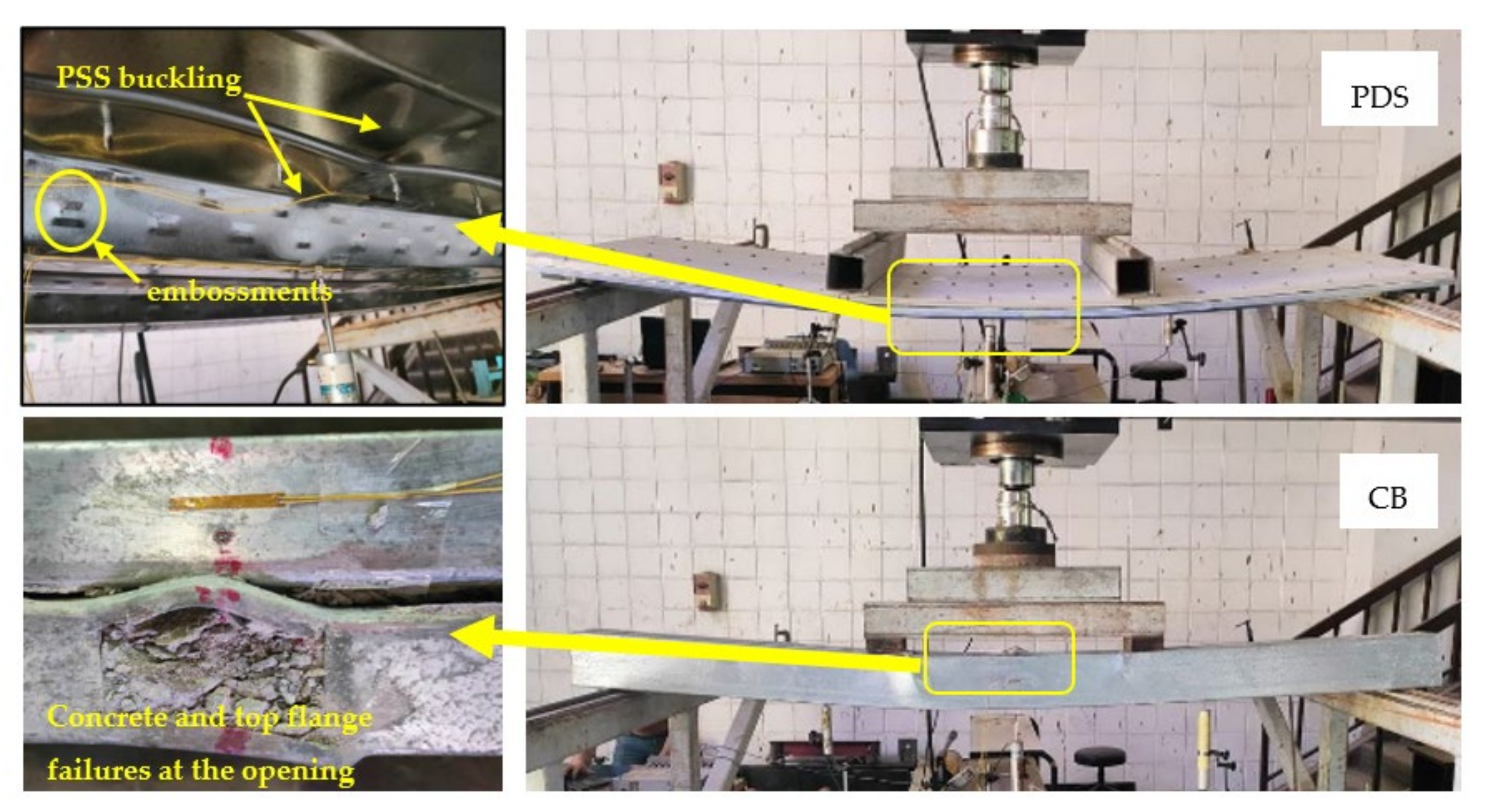
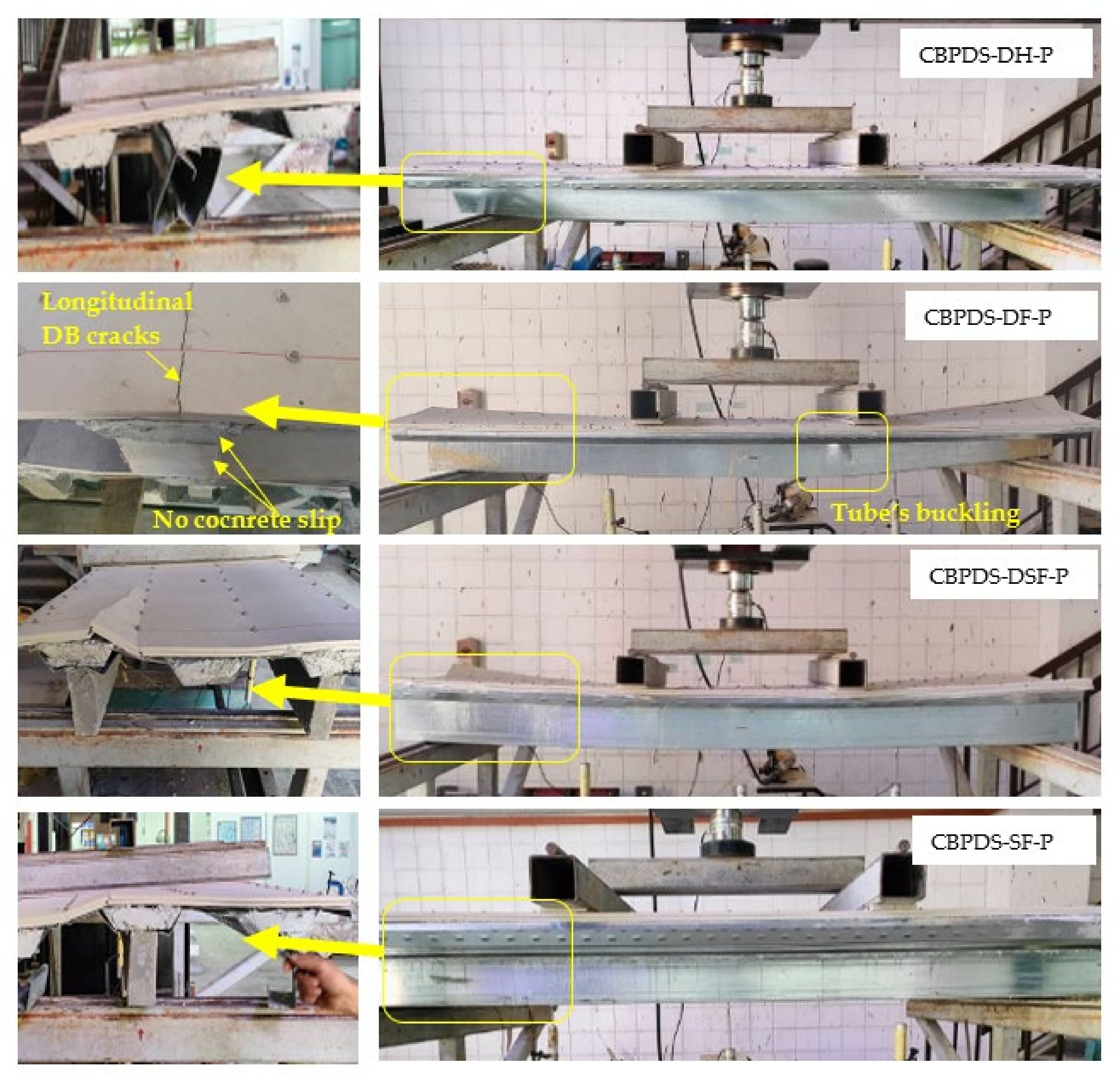
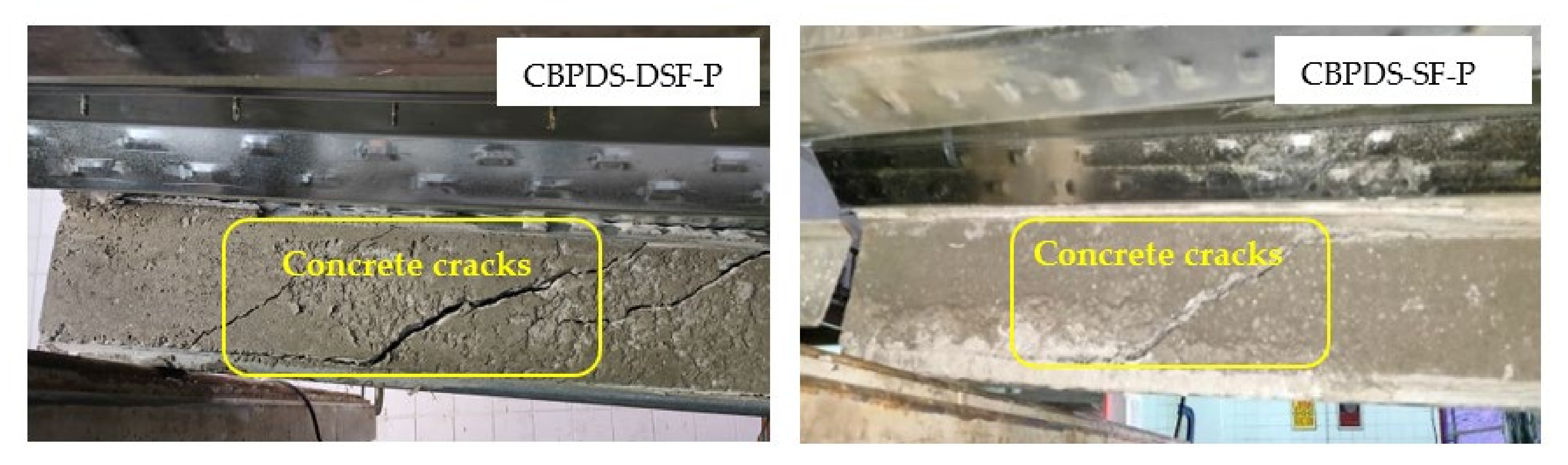
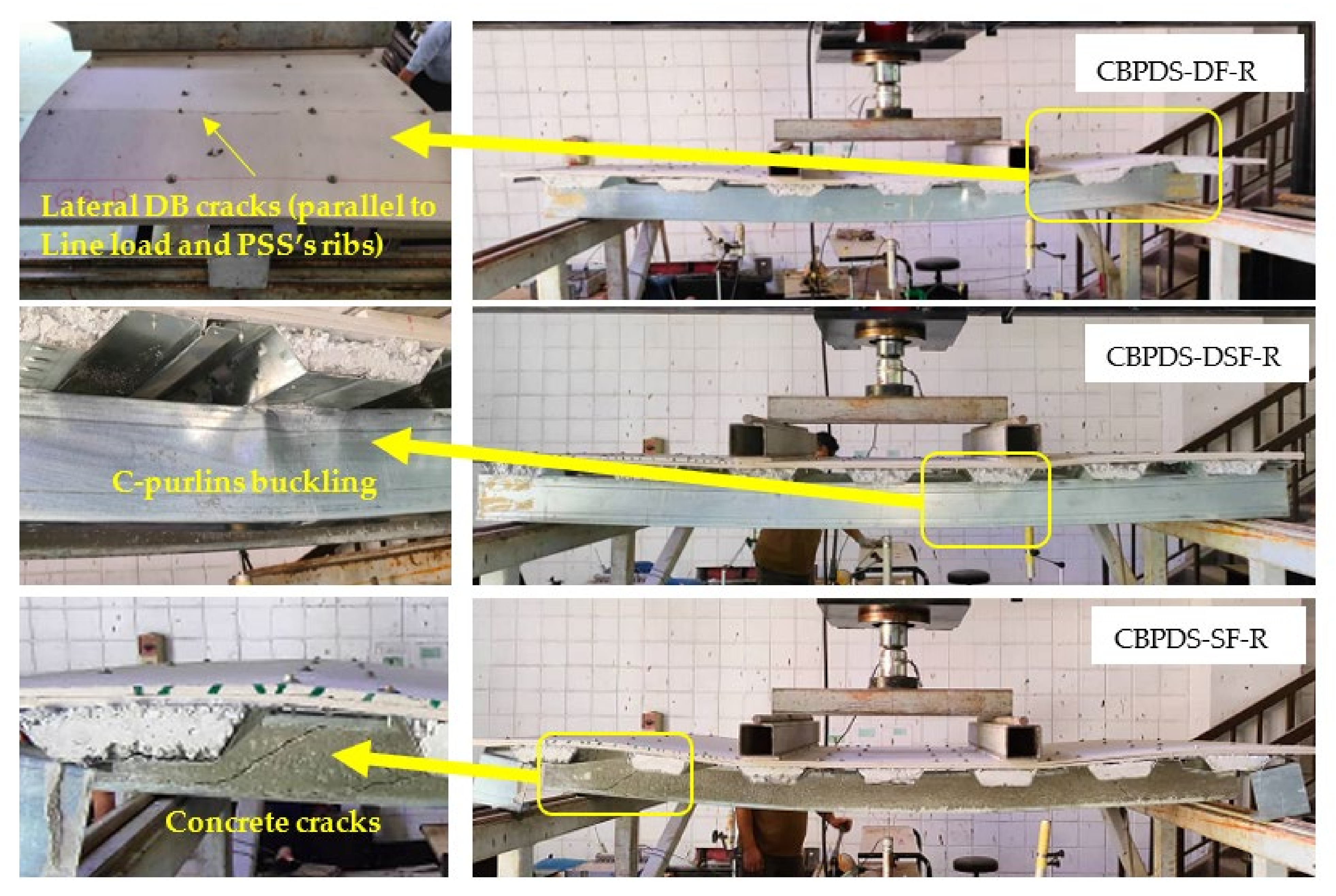
3.1. Failure Modes

All tested composite beam–slab specimens in this research are simply supported members. Thus, at a distance between the two-point loads, these specimens showed typical bending behavior with compression stress at the top surface of their slabs and tension stress at the bottom flange of their beams [38]. The specimens’ tests continued beyond their bending capacities, including the control slab (specimen PDS) and control beam (specimen CB), as shown in Figure 9. Due to that, local buckling failure was observed at the top flanges and webs of PSS elements since they are subjected to high compression stress. Even though there were no obvious failures, such as cutting/slipping for the screw connectors between the DB and PSS parts until the end of the test, it confirmed the perfect bond interaction between these two parts had been achieved. Additionally, it is worth mentioning that the existence of embossments at the webs and bottom flanges of the Peva 50 sheet (PSS) has succeeded in generating a partial connection with the infill concrete, and yet, a limited slip failure between the layers occurred at extreme loading stage, which is unavoidable [9]. The same steel buckling failure scenario was observed at the top flange of the control beam (specimen CB), which started to occur when the load reached about 85–90% of the beam’s bending capacity. Thereafter, the concrete core starts to crush due to the high compression stress, as clearly seen from the openings located at the top flange (see Figure 9).
Accordingly, for both of the control specimens, PDS and CB, the infill concrete sufficiently prevented the inward local buckling of their steel parts (PSS and C-purlins, respectively), which led to improving their flexural behavior (strength, stiffness, and ductility), much similar to the conventional CFST beams and PSSDB slabs those tested by others [33,35]. Remarkably, there are two interesting outcomes were recorded for the tested control beam in this study. First, the double C-purlins that are placed face-to-face on preparing the tube of specimen CB are connected by using the concrete core alone (without using additional screws/welding connectors), which was achieved due to the perfect bonding interaction between the concrete core and lips of these C-purlins [37]. This performance was continued until the applied load reached about 90% of the specimen’s loading capacity; after that, the bond between these two pieces started to slowly open, specifically under the point load and mid-span distance due to the high compression stress. Second, the permanent openings provided at the top flange of specimen CB did not cause major weakness in the beam’s bending behavior. However, the edges around these openings started to buckle and twist when the load reached about 90% of the specimen’s loading capacity, as shown in Figure 9.
The CBPDS specimen with double hollow C-purlins (CBPDS-DH-P) exhibited twisting failure for the beam’s cross-section at supports, which started at the early loading stage, as shown in Figure 10. This occurs because the tube is too slender to resist the compression force that is transferred directly from the support’s reaction [37]. Therefore, the major enhancement in the flexural performance (bending behavior, loading capacity, stiffness, and ductility) was achieved by the same tube’s cross-section when filled with concrete material (specimen CBPDS-DF-P) since the twisting/inward buckling failures of this tube were sufficiently prevented. In general, the concrete-filled CBPDS specimens with PSS deck slab placed parallel to their span’s direction (CBPDS-DF-P, CBPDS-DSF-P, and CBPDS-SF-P) showed typical flexural performance, although they were prepared with different C-purlin beams configurations, as presented in Figure 10. These specimens exhibited outward buckling failure at the top flanges of their beams near the point loads, which started when the loading test reached about 85–90% of their loading capacity. At the same loading stage, longitudinal cracks (parallel to specimen direction) at the top surface of DB sheets started near to supports; also, no crush failure was seen for the DB sheet at the mid-span distance, which is usually subjected to high compression stress (see Figure 10). Furthermore, due to the high shear stress located at the shear span distance (point load to support distance), concrete cracks were started when the loading test reached about 70–75% of the specimens’ loading capacities, which was seen for specimens with single and double separate C-purlins beams (CBPDS-DSF-P and CBPDS-SF-P), as highlighted in Figure 11. Even though these cracks were increased gradually with the increases of the testing load, there was no slip failure seen/recorded between the concrete core and the cold-formed sections, neither that provided inside the PSS deck slab nor the C-purlins beam.
Generally, the same flexural behavior was exhibited for the concrete-filled CBPDS specimens with perpendicular PSS direction (CBPDS-DF-R, CBPDS-DSF-R, and CBPDS-SF-R), as shown in Figure 12. Specifically, the same failure modes of C-purlin’s buckling, concrete cracks inside the C-purlins, and no slipping failure for the concrete core inside the C-purlins beams and PSS slab. However, their DB sheets start to crack in the lateral direction (perpendicular to specimen direction) when the loading stage reaches about 70–75% of their specimens’ loading capacities, as shown in Figure 12 for specimen CBPDS-DF-R, as an example. Probably, this DB’s cracks scenario occurred due to the fact that the PSS’s ribs of these specimens were placed in a perpendicular direction (parallel to the applied load direction) and, thus, well led to cause some weakness to the PDS slap part. However, no failures were recorded for the self-tapping screws and concrete connectors of these specimens with perpendicular PSS direction, which also confirmed the perfect bonding interaction between their components (CB, PSS, and DB). Lastly, due to the influence of infill concrete materials, all CBPDS specimens with parallel and perpendicular PSS directions are deflected almost similar to the half-sine curves, as compared at different loading stages in Figure 13 and Figure 14, respectively.

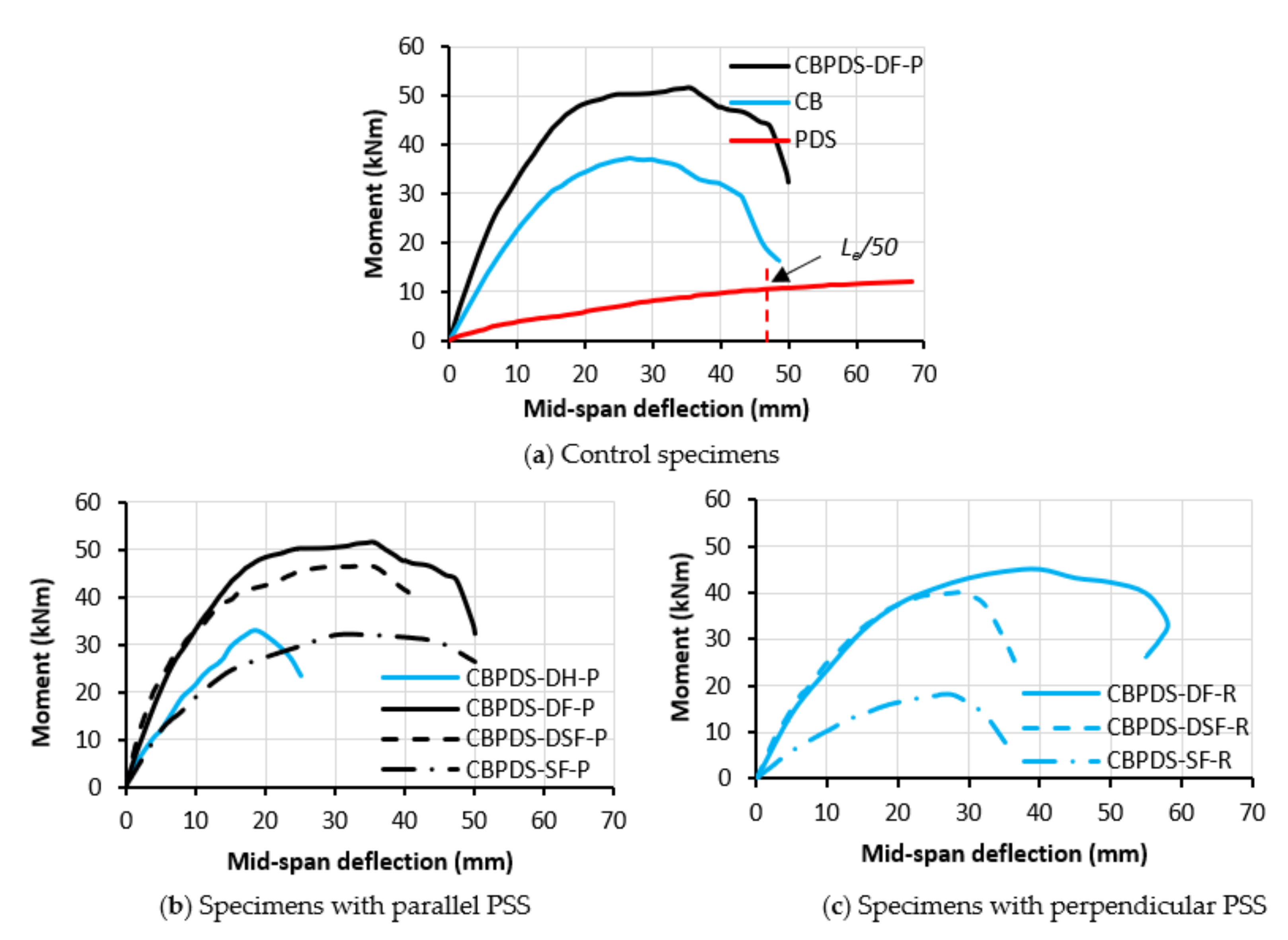
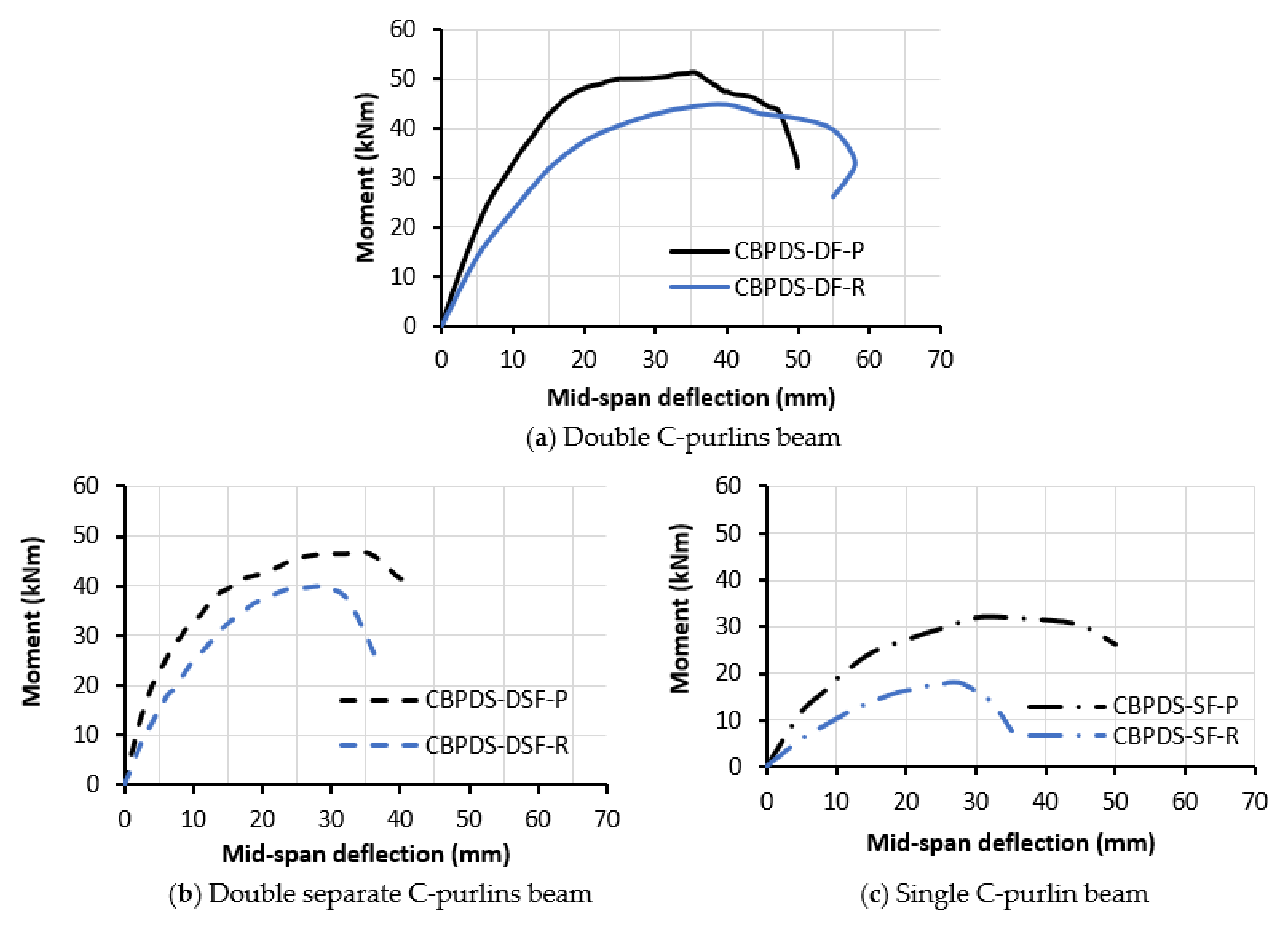
3.2. Moment vs. Deflection Relationship

The comparisons between moment–deflection relationships of the control beam (specimen CB), control slab (specimen PDS), and combined beam–slab specimen CBPDS-DF-P are presented in Figure 15a. The control slab showed limited elastic behavior at the earlier loading stage, followed by continuous elastic–plastic behavior until the end of the test, which behaved very ductile even after passing its ultimate bending capacity that measured at a deflection limit equal to Le/50 [38,46]. This is due to the influence of infill concrete material that prevented/delayed the PSS’ buckling failure and also because of the sufficient interactions between the concrete core, PSS, and DB parts, while the control beam showed stiffer flexural behavior than the slab at the elastic loading stage until it reached about 60% of its bending capacity and then showed elastic–plastic behavior with a continuously decreasing in the curve’s slope since the tube started to buckle at the point loads. After that, the beam’s moment–deflection curve behaved fully plastic until it achieved the ultimate bending capacity (peak value at the curve), and then, the curve’s slope rapidly dropped due to the extreme tube’s buckling failure and concrete crushing at the top flange. Generally, the combined beam–slab specimen CBPDS-DF-P showed stiffer flexural performance than both of the control specimens (CB and PDS). This improvement was achieved due to the sufficient interactions between the concrete core and the cold-formed steel sections (no slip failure) and the perfect connections between the specimen’s components (double C-purlins, PSS, and DB).
The moment–deflection relationships of the CBPDS specimens with different C-purlins configurations (double, double separate, and single) and parallel PSS deck slab direction are presented in Figure 15b. Generally, the flexural performance (stiffness, strength, and ductility) of the CBPDS specimen with double C-purlins beam was majorly improved due to the effects of infill concrete material, as compared to the curves of specimens CBPDS-DH-P and CBPDS-DF-P. Using a double C-purlins beam with face-to-face connection for the suggested composite system (specimen CBPDS-DF-P) showed slightly better flexural performance than that with double separate C-purlins (CBPDS-DSF-P); this is due to the sufficient concrete confinement behavior that achieved by the double C-purlins when fabricated as a closed tube cross-section [37]. On the other hand, using single C-purlin beam filled with concrete (specimen CBPDS-SF-P) achieved almost the same bending strength as that fabricated with hollow double C-purlins (CBPDS-DH-P) but with much better ductility behavior since it failed at a higher deflection limit (see Figure 15b). In general, the same flexural performance was recorded for the CBPDS specimens with perpendicular PSS direction, as the related moment–deflection relationships presented in Figure 15c. However, regardless of the C-purlins beam’s configuration, the CBPDS specimen with parallel PSS deck slab direction showed stiffer flexural performance and achieved higher bending capacity than the corresponding specimen with perpendicular PSS direction, as compared in Figure 16. This is due to the influence of PSS’s ribs’ direction when placed parallel to the specimen’s span, which can sufficiently share the bending strength together with the beam part. Additionally, when the PSS is in a parallel direction, the concrete core can, together with the DB and PSS parts, resist the high compression stress that is generated at the top cross-section (mid-span) of these CBPDS specimens due to the bending load.

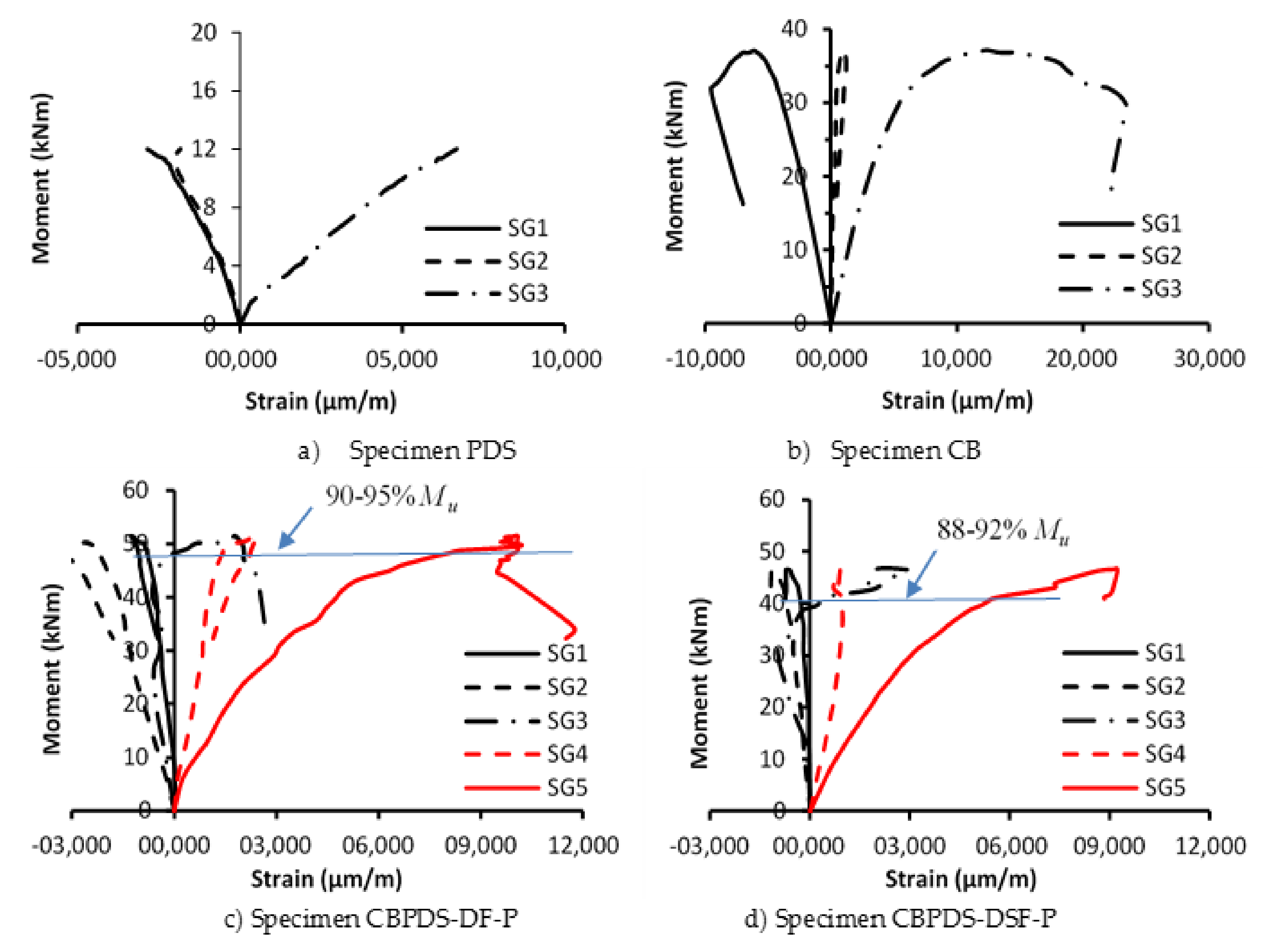
3.3. Moment vs. Strain Relationship

The relationships between bending moment versus strain values of the tested specimens are presented in Figure 17, where the strain gauge locations are shown in the earlier Figure 8. For the control slab (specimen PDS), the strain gauges SG1 and SG2 recorded compression (−ve) values which gradually increased with the increases of bending moment since they are fixed at the top surface of DB and top-flange of PSS, respectively, and at the mid-span of specimen PDS, while the strain gauge SG3 located at the bottom flange of specimen PDS gradually increased tension (+ve) strain values with the increases in bending moment, as shown in Figure 17a. Generally, the same performance was recorded for the control beam (specimen CB), specifically for the strain gauges SG1 and SG3, which are located at the top and bottom flanges, respectively, whereas the strain gauge SG2 located at the mid-depth of specimen CB showed a limited continuous increase in the tensile strain (+ve) value with the increases of bending moment, confirming the upward movement of the neutral axis (N.A) at the cross-section of this specimen [37], as shown in Figure 17b.
Furthermore, Figure 17c presents the moment–strain relationships of the CBPDS specimen with a double-filled C-purlins beam (CBPDS-DF-P). During the test, the strain gauges SG1 and SG2 of this specimen showed a continuous increase in compression (−ve) strain values since they are located at the mid-span top flange of the specimen’s slab part. While the strain gauges, SG4 and SG5 showed an increase in their tensile (+ve) strain values since they are located at the bottom flange of the specimen’s beam part. In addition, it is interesting to realize that the strain gauge SG3 which is located at the interaction level between the beam (CB) and slab (PDS) parts of specimen CBPDS-DF-P recorded slight compression (−ve) strain values during the loading test, which means the N.A of the specimen’s cross-section is still located under the beam’s top flange. Then, after the loading test reached about 90–95% of the specimen’s moment capacity, the SG3 started to record tensile (+ve) strain values, confirming that the N.A starts to move above the beam’s top flange (slightly above the beam–slab interaction level). In general, the same moment–strain relationships have been recorded for the specimen with double separate C-purlins beam (specimen CBPDS-DSF-P), as shown in Figure 17d. However, the N.A of this specimen starts to move above the beam–slab interaction level at a slightly lower loading stage (80–85% of specimen’s capacity); this is attributed to the earlier concrete cracking that occurs at the double separate C-purlins beam of the CBPDS specimen (low concrete confinement), which leads in return to lower flexural performance compared to that occurred when used double face-to-face connection C-purlins beam.

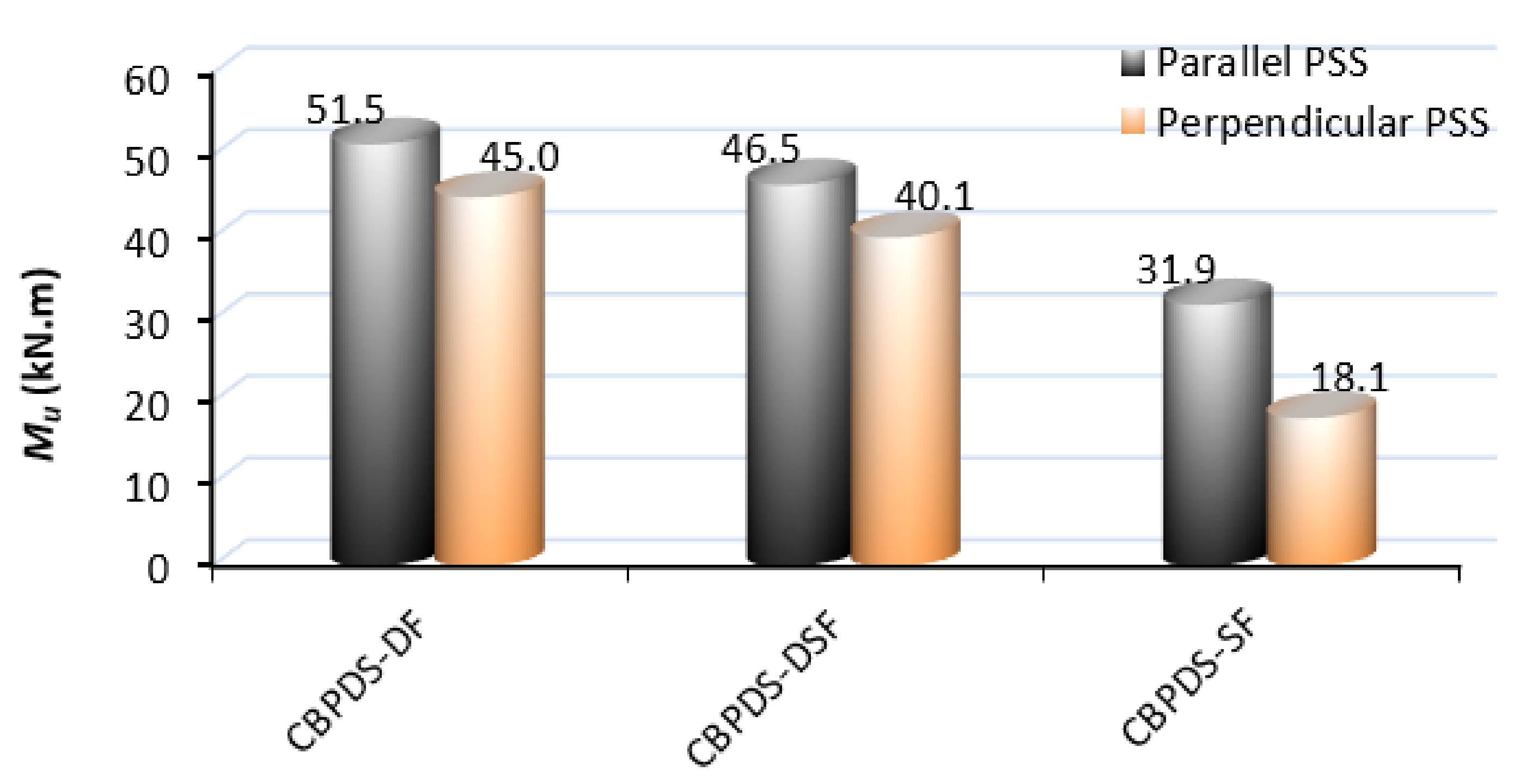
3.4. Carrying Moment Capacity

The ultimate moment capacity (Mu) of the investigated CBPDS specimens was estimated from the peak value recorded at the related moment–deflection curves or from the moment value relevant to the deflection limit equal to Le/50 [38,46], whichever one was achieved earlier. The Mu values and the corresponding ultimate applied load (Pu) of the tested specimens are presented in Table 1 and Figure 8. Table 1 also presents the load reduction percentages between the achieved load values of specimens with different C-purlins configurations (double separate single; double hollow) and the value of their control specimen (double face-to-face C-purlins connection) in each group of specimens with parallel and perpendicular PSS directions. For the CBPDS specimens with parallel PSS direction, the specimen with double filled C-purlins beam (face-to-face connection) is considered a reference sample (CBPDS-DF-P). The moment capacity of this specimen is equal to 51.5 kN·m, which was reduced to 32.8 kN·m (−36%) when the same specimen used a double hollow C-purlins beam, and this is due to the absence of influence of the infill concrete material. On the other hand, the same Mu value of specimen CBPDS-DF-P was reduced to 46.5 kN·m, which is about −10% when using double separate C-purlins beam (specimen CBPDS-DSF-P), since these C-sections could not sufficiently confine the concrete core when they are separate, unlike when they are closed as a tube [37]. Lastly, using a concrete-filled single C-purlin beam (CBPDS-SF-P) led to reducing the specimen’s bending capacity by about 38%, compared to the value of specimen CBPDS-DF-P.
In general, the same above scenario was recorded for the CBPDS specimens with perpendicular PSS directions, as compared in Figure 18. However, the reduction percentages are different when compared to the related reference specimen CBPDS-DF-R, and this is due to the fewer effects was achieved when the PSS’s ribs placed in a perpendicular direction, which could not well resist the bending stresses compared when placed in parallel direction.

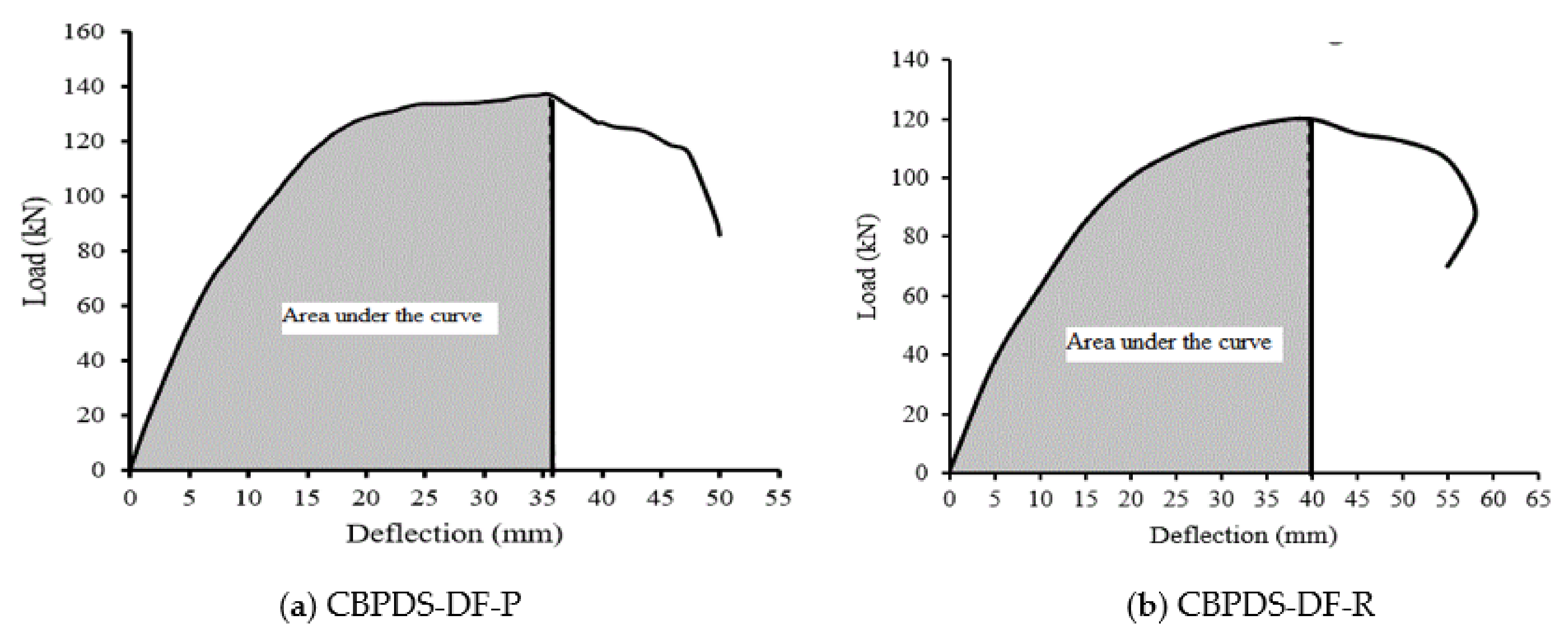
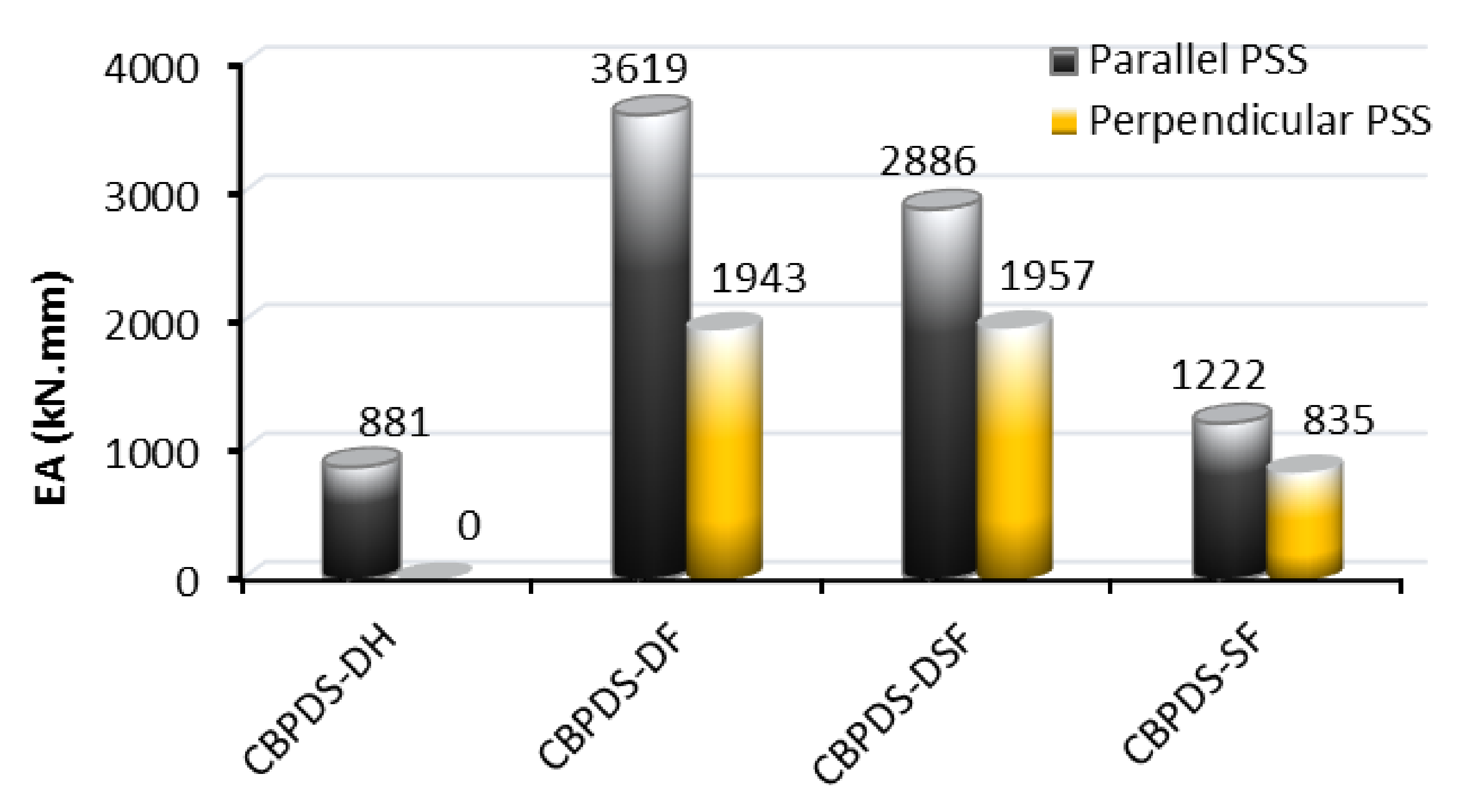
3.5. Energy Absorption (EA) Index

This section discusses the capability of the suggested CBPDS specimens to absorb the energy under static bending loads. In this research, the energy absorption (EA) index of these specimens is estimated from the cumulative area under their load–deflection curves up to the limit of their ultimate loading capacity [37,38], as illustrated in Figure 19. The EA indices of the tested CBPDS specimens are presented in Table 1 and Figure 20. For the specimens with parallel PSS direction, it is noticed that the specimen with double hollow C-purlins (CBPDS-DH-P) achieved an EA value equal to 881 kN·mm, where this value was majorly increased to 3619 kN·mm (4.1 times) when the same double C-purlins beam was filled with concrete material (CBPDS-DF-P) since both of the bending strength and ductility behavior of the specimen was improved accordingly. However, the EA value of the reference specimen CBPDS-DF-P was reduced to 2886 kN·mm (−20%) when only separating the double C-purlins beam (specimen CBPDS-DSF-P). Furthermore, using a single C-purlin beam filled with concrete instead of double sections for the CBPDS composite specimen (CBPDS-SF-P) led to reducing the EA value to 1222 kN·mm, which is about 66% less than that achieved when using double-filled C-purlins (CBPDS-DF-P). However, this value of specimen CBPDS-SF-P is around 1.4 times higher than that of the specimen with double hollow C-purlins (CBPDS-DH-P) since the infill concrete improved the specimen’s ductility. Generally, the same energy absorption performance was recorded for the CBPDS specimen with PSS directions but with different values and percentages of reduction, as compared in Figure 20.

4. Conclusions

This research investigated the flexural performance of a newly suggested composite CBPDS specimen under a static bending load, and the conclusions are as follows:
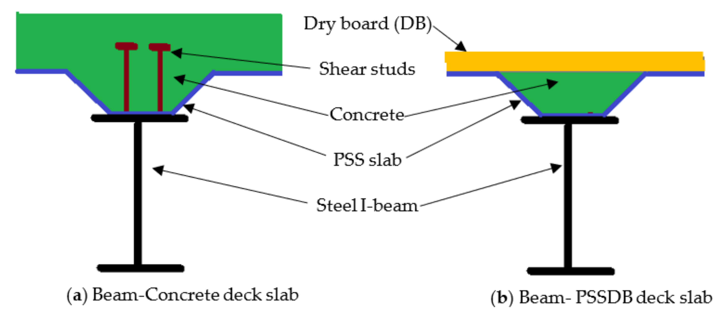
  • A perfect bond interaction was achieved between the cold-formed beams (CB) and the PSSDB deck slabs (PDS) by using steel self-tapping screws and concrete shear connectors. Thus, a sufficient flexural performance was achieved by the suggested composite beam–slab system (CBPDS specimen).
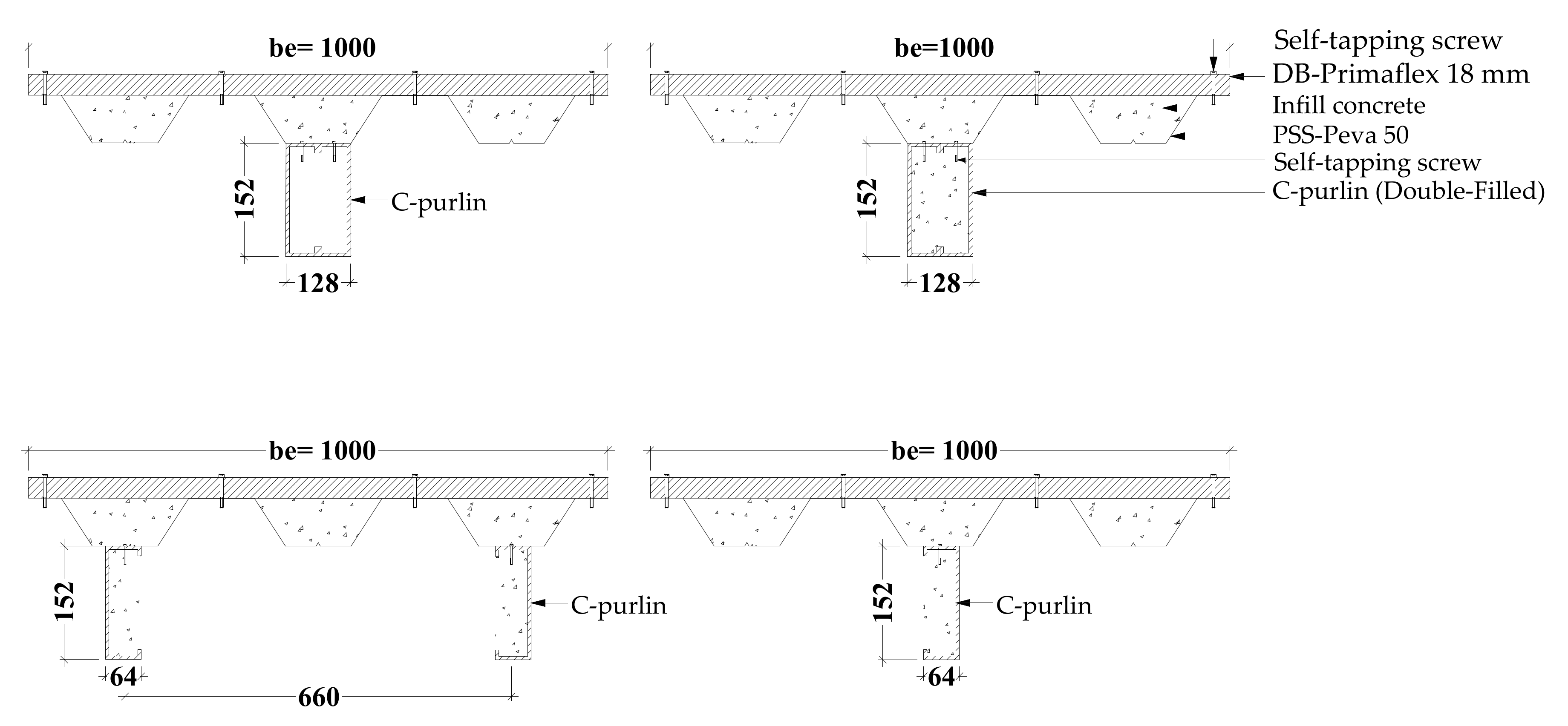
  • Filling the double C-purlins steel beam with concrete material significantly improved the flexural performance of the composite CBPDS specimen. For example, the bending capacity of the CBPDS specimen with the double hollow C-purlins beam was increased by approximately 57% when filled with the concrete materials because inward and twisting failures of the cold-formed steel tube were prevented.
  • Using concrete-filled double C-purlins with a face-to-face connection in the composite CBPDS specimen showed an almost similar bending behavior to that seen when using double separate C-purlins but with slightly higher bending capacity (+10%) due to the better concrete confinement that was achieved when the C-purlins fabricated as closed tube’s shape. Additionally, the CBPDS specimen with a single C-purlins beam achieved a lower bending capacity (−32%) than that with double C-purlins.
  • Generally, the composite CBPDS specimens fabricated with a PSS deck slab placed in a perpendicular direction showed a similar flexural performance to the corresponding specimens with parallel PSS direction but with lower bending moment capacities of about 13–40% (depending on the C-purlins beams configurations). This is due to the weakness in the PSS deck slab part when its ribs are placed in a perpendicular direction, which could not resist the bending stresses when subjected to bending load.
  • Regardless of the C-purlins beam’s configuration, the composite CBPDS specimens filled with concrete materials have sufficiently absorbed the energy generated from the static bending load. The energy absorption values achieved by the specimens with parallel PSS direction were approximately 30–35% higher than those of corresponding specimens with perpendicular direction.
The above conclusions are limited to the newly suggested composite CBPDS system that was tested in this research. Further experimental and numerical investigations are required to study the influence of other parameters that have not yet been investigated to establish a new analytical method that can theoretically estimate the flexural strength and stiffness of this new composite member.

Author Contributions

Conceptualization, M.C.L., A.W.A.Z. and A.A.M.; Data curation, M.C.L., A.W.A.Z. and M.F.A.; Formal analysis, M.C.L., A.W.A.Z. and M.F.A.; Funding acquisition, A.W.A.Z. and A.A.M.; Investigation, M.C.L. and M.F.A.; Methodology, A.W.A.Z., A.A.A. and S.J.H.; Project administration, A.W.A.Z., A.A.M. and A.A.A.-A.; Validation, S.J.H. and W.M.T.; Resources, A.W.A.Z., A.A.A. and A.A.M.; Software, A.W.A.Z.; Supervision, A.W.A.Z. and A.A.A.-A.; Visualization, W.M.T.; Writing—original draft, A.W.A.Z. and M.C.L.; Writing—review and editing, A.A.A., A.A.A.-A. and W.M.T. All authors have read and agreed to the published version of the manuscript.

Funding

This research was funded by Investigation & Instrumentation Management Center (CRIM), Universiti Kebangsaan Malaysia (UKM), funding number “GGPM-2020-001”.

Institutional Review Board Statement

Not applicable.

Informed Consent Statement

Not applicable.

Data Availability Statement

Data are presented in the article.

Acknowledgments

The authors highly acknowledge their Institutes and Universities for their support in preparing and completing this research.

Conflicts of Interest

The authors declare no conflict of interest.

Abbreviations

Cold-formed beam (CB), Profile steel sheet (PSS), dry board (DB), PSS slab covered with DB (PSSDB/PDS), Energy absorption (EA), modulus of elasticity for concrete (Ec), modulus of elasticity for steel (Es), concrete cube compressive strength at 28 days (fcu), ultimate tensile strength of steel (fu), yield tensile strength of steel (fy), ultimate bending moment capacity (flexural strength capacity; Mu), effective length (Le), steel C-section thickness (t), strain gauge (SG).

References

  1. Wright, H.D.; Evans, H.R. A folded plate method of analysis for profiled steel sheeting in composite floor construction. Thin Walled Struct. 1987, 5, 21–37. [Google Scholar] [CrossRef]
  2. Wright, H.D.; Evans, H.R.; Burt, C.A. Profiled steel sheet/dry boarding composite floors. Struct. Eng. Part A J. Inst. Struct. Eng. 1989, 67, 114–120. [Google Scholar]
  3. Ahmed, E. Behavior of Profiled Steel Sheet Dry Board Folded Plate Structures. Ph. D. Thesis, Universiti Kebangsaan Malaysia, Selangor, Malaysia, 1999. [Google Scholar]
  4. Wan Badaruzzaman, W.H.; Evans, H.R. Profiled steel sheeting dry board system as an alternative to traditional forms of construction. In An International Conference on Advanced Stratey Technology UKM; Faculty of Engineering, Universiti Kebangsaan Malaysia: Kuala Lumpur, Malaysia, 1995. [Google Scholar]
  5. Wan Badaruzzaman, W.H.; Ahmed, E.; Rashid, K. Out-of Plane Bending Stiffness along the Major Axis of Proflled Steel Sheet Dryboard Composite Floor Panels. J. Kejuruter. 1996, 8, 79–95. [Google Scholar]
  6. Seraji, M.; Badaruzzaman, W.W.; Osman, S. Membrane action in profiled steel sheeting dry board (PSSDB) floor slab system. J. Eng. Sci. Technol. 2013, 8, 57–68. [Google Scholar]
  7. Roslan, A.; Majid, M.; Jaini, Z.; Sutiman, N. Characterization of Bond-Slip Behaviour of the Profiled Steel Sheet Dry Board (PSSDB) Composite System Aina. Int. J. Integr. Eng. 2021, 13, 329–336. [Google Scholar] [CrossRef]
  8. Al-Shaikhli, M.; Badaruzzaman, W.; Al Zand, A. Experimental and numerical study on the PSSDB system as two-way floor units. Steel Compos. Struct. 2022, 42, 33–48. [Google Scholar] [CrossRef]
  9. Jaffar, M.; Badaruzzaman, W.; Baharom, S. Experimental tests on bending behavior of profiled steel sheeting dry board composite floor with geopolymer concrete infill. Lat. Am. J. Solids Struct. 2016, 13, 272–295. [Google Scholar] [CrossRef]
  10. Al-Shaikhli, M.; Badaruzzaman, W.W.; Baharom, S.; Al Zand, A. The two-way flexural performance of the PSSDB floor system with infill material. J. Constr. Steel Res. 2017, 138, 79–92. [Google Scholar] [CrossRef]
  11. Jaffar, M.I.; Wan Badaruzzaman, W.H.; Al Bakri Abdullah, M.M.; Abd Razak, R. Comparative study floor flexural behavior of profiled steel sheeting dry board between normal concrete and geopolymer concrete in-filled. In Applied Mechanics and Materials; Trans Tech Publications: Zurich, Switzerland, 2015; pp. 364–368. [Google Scholar]
  12. Fernando, P.; Jayasinghe, M.; Jayasinghe, C. Structural feasibility of Expanded Polystyrene (EPS) based lightweight concrete sandwich wall panels. Constr. Build. Mater. 2017, 139, 45–51. [Google Scholar] [CrossRef]
  13. Hilo, S.J.; Badaruzzaman, W.W.; Osman, S.; Al Zand, A. Axial Load Behavior of Acomposite Wall Strengthened with an Embedded Octagon Cold-Formed Steel. Appl. Mech. Mater. 2015, 754–755, 437–441. [Google Scholar] [CrossRef]
  14. Hilo, S.; Badaruzzaman, W.W.; Osman, S.; Al Zand, A.; Samir, M.; Hasan, Q. A state-of-the-art review on double-skinned composite wall systems. Thin Walled Struct. 2015, 97, 74–100. [Google Scholar] [CrossRef]
  15. Claasen, J.; Walls, R.; Cicione, A.; Streicher, D. Large-scale experimental testing and numerical modelling of a modular cellular beam system. J. Constr. Steel Res. 2022; under review. [Google Scholar] [CrossRef]
  16. Kim, H.-Y.; Jeong, Y.-J. Steel–concrete composite bridge deck slab with profiled sheeting. J. Constr. Steel Res. 2009, 65, 1751–1762. [Google Scholar] [CrossRef]
  17. Gase, P.M.; Kaczinski, M.R. The history and benefits of prefabricated grid reinforced concrete decks. In Safety and Reliability of Bridge Structures; CRC Press: Boca Raton, FL, USA, 2009; pp. 423–428. [Google Scholar]
  18. Nakamura, S.; Momiyama, Y.; Hosaka, T.; Homma, K. New technologies of steel/concrete composite bridges. J. Constr. Steel Res. 2002, 58, 99–130. [Google Scholar] [CrossRef]
  19. Han, L.; Li, W.; Bjorhovde, R. Developments and advanced applications of concrete-filled steel tubular (CFST) structures: Members. J. Constr. Steel Res. 2014, 100, 211–228. [Google Scholar] [CrossRef]
  20. Shao, C.; Ju, J.; Han, G.; Qian, Y. Seismic applicability of a long-span railway concrete upper-deck arch bridge with CFST rigid skeleton rib. Struct. Eng. Mech. 2017, 61, 645–655. [Google Scholar] [CrossRef]
  21. Han, L.H. Flexural behaviour of concrete-filled steel tubes. J. Constr. Steel Res. 2004, 60, 313–337. [Google Scholar] [CrossRef]
  22. Han, L.; Yang, Y.; Tao, Z. Concrete-filled thin-walled steel SHS and RHS beam-columns subjected to cyclic loading. Thin Walled Struct. 2003, 41, 801–833. [Google Scholar] [CrossRef]
  23. Wang, W.-H.; Han, L.-H.; Li, W.; Jia, Y.-H. Behavior of concrete-filled steel tubular stub columns and beams using dune sand as part of fine aggregate. Constr. Build. Mater. 2014, 51, 352–363. [Google Scholar] [CrossRef]
  24. Moon, J.; Roeder, C.; Lehman, D.; Lee, H.-E. Analytical modeling of bending of circular concrete-filled steel tubes. Eng. Struct. 2012, 42, 349–361. [Google Scholar] [CrossRef]
  25. Zhan, Y.; Zhao, R.; Ma, Z.; Xu, T.; Song, R. Behavior of prestressed concrete-filled steel tube (CFST) beam. Eng. Struct. 2016, 122, 144–155. [Google Scholar] [CrossRef]
  26. Ren, Q.-X.; Han, L.-H.; Lam, D.; Li, W. Tests on elliptical concrete filled steel tubular (CFST) beams and columns. J. Constr. Steel Res. 2014, 99, 149–160. [Google Scholar] [CrossRef]
  27. Al Zand, A.; Badaruzzaman, W.W.; Tawfeeq, W. New empirical methods for predicting flexural capacity and stiffness of CFST beam. J. Constr. Steel Res. 2020, 164, 105778. [Google Scholar] [CrossRef]
  28. Wang, R.; Han, L.; Nie, J.; Zhao, X. Flexural performance of rectangular CFST members. Thin Walled Struct. 2014, 79, 154–165. [Google Scholar] [CrossRef]
  29. Shen, Y.; Tu, Y.; Huang, W. Flexural Strength Evaluation of Multi-Cell Composite L-Shaped Concrete-Filled Steel Tubular Beams. Buildings 2022, 12, 39. [Google Scholar] [CrossRef]
  30. Shen, Y.; Tu, Y. Flexural strength evaluation of multi-cell composite T-shaped concrete-filled steel tubular beams. Materials 2021, 14, 2838. [Google Scholar] [CrossRef] [PubMed]
  31. Elchalakani, M.; Zhao, X. Concrete-filled cold-formed circular steel tubes subjected to variable amplitude cyclic pure bending. Eng. Struct. 2008, 30, 287–299. [Google Scholar] [CrossRef]
  32. Fang, C.; Zhou, F.; Luo, C. Cold-formed stainless steel RHSs/SHSs under combined compression and cyclic bending. J. Constr. Steel Res. 2018, 141, 9–22. [Google Scholar] [CrossRef]
  33. Al Zand, A.; Badaruzzaman, W.W.; Ali, M.; Hasan, Q.; Al-Shaikhli, M. Flexural performance of cold-formed square CFST beams strengthened with internal stiffeners. Steel Compos. Struct. 2020, 34, 123–139. [Google Scholar] [CrossRef]
  34. Sifan, M.; Gatheeshgar, P.; Navaratnam, S.; Nagaratnam, B.; Poologanathan, K.; Thamboo, J.; Suntharalingam, T. Flexural behaviour and design of hollow flange cold-formed steel beam filled with lightweight normal and lightweight high strength concrete. J. Build. Eng. 2021, 48, 103878. [Google Scholar] [CrossRef]
  35. Al Zand, A.; Badaruzzaman, W.W.; Al-Shaikhli, M.; Ali, M. Flexural performance of square concrete-filled steel tube beams stiffened with V-shaped grooves. J. Constr. Steel Res. 2020, 166, 105930. [Google Scholar] [CrossRef]
  36. Al Zand, A.; Alghaaeb, M.; Liejy, M.; Mutalib, A.; Al-Ameri, R. Stiffening Performance of Cold-Formed C-Section Beam Filled with Lightweight-Recycled Concrete Mixture. Materials 2022, 15, 2982. [Google Scholar] [CrossRef] [PubMed]
  37. Al Zand, A.; Ali, M.; Al-Ameri, R.; Badaruzzaman, W.; Tawfeeq, W.; Hosseinpour, E.; Yaseen, Z. Flexural Strength of Internally Stiffened Tubular Steel Beam Filled with Recycled Concrete Materials. Materials 2021, 14, 6334. [Google Scholar] [CrossRef] [PubMed]
  38. Al Zand, A.; Hosseinpour, E.; Badaruzzaman, W.; Ali, M.; Yaseen, Z.; Hanoon, A. Performance of the novel C-purlin tubular beams filled with recycled-lightweight concrete strengthened with CFRP sheet. J. Build. Eng. 2021, 43, 102532. [Google Scholar] [CrossRef]
  39. Huang, H.; Chen, K.; Wu, Q.; Nakamura, S. Fatigue Performance Test and Numerical Analysis of Composite Girders with CSW-CFST Truss Chords. Appl. Sci. 2022, 12, 5459. [Google Scholar] [CrossRef]
  40. Han, L.-H.; Xu, W.; He, S.-H.; Tao, Z. Flexural behaviour of concrete filled steel tubular (CFST) chord to hollow tubular brace truss: Experiments. J. Constr. Steel Res. 2015, 109, 137–151. [Google Scholar] [CrossRef]
  41. Xu, W.; Han, L.; Tao, Z. Flexural behaviour of curved concrete filled steel tubular trusses. J. Constr. Steel Res. 2014, 93, 119–134. [Google Scholar] [CrossRef]
  42. Kang, J.-Y.; Choi, E.-S.; Chin, W.-J.; Lee, J.-W. Flexural behavior of concrete-filled steel tube members and its application. Steel Struct. 2007, 7, 319–324. [Google Scholar]
  43. Farhan, K.; Shallal, M. Experimental behaviour of concrete-filled steel tube composite beams. Arch. Civ. Eng. 2020, 66, 235–251. [Google Scholar] [CrossRef]
  44. Dabbagh, N.; Badaruzzaman, W.W.; Al Zand, A.; Azad, S.K.; Uy, B.; Azmi, M.; Alatshan, F. A systematic review on CFST members under impulsive loading. Thin Walled Struct. 2022, 179, 109503. [Google Scholar] [CrossRef]
  45. Liao, F.-Y.; Han, L.-H.; He, S.-H. Behavior of CFST short column and beam with initial concrete imperfection: Experiments. J. Constr. Steel Res. 2011, 67, 1922–1935. [Google Scholar] [CrossRef]
  46. Javed, M.; Sulong, N.R.; Memon, S.; Rehman, S.-U.; Khan, N. Flexural behaviour of steel hollow sections filled with concrete that contains OPBC as coarse aggregate. J. Constr. Steel Res. 2018, 148, 287–294. [Google Scholar] [CrossRef]
Figure 1. Composite steel beam–slab system.
Buildings 13 00432 g001
Figure 2. Specimens designation ID.
Buildings 13 00432 g002
Figure 3. CBPDS specimen with parallel PSS direction (all dimensions in mm).
Buildings 13 00432 g003
Figure 4. CBPDS cross-section with parallel PSS direction (all dimensions in mm).
Buildings 13 00432 g004
Figure 5. CBPDS specimen with perpendicular PSS direction (all dimensions in mm).
Buildings 13 00432 g005
Figure 6. CBPDS cross-section with perpendicular PSS direction (all dimensions in mm).
Buildings 13 00432 g006
Figure 7. Preparing the CBPDS specimens.
Buildings 13 00432 g007
Figure 8. Schematic test setup of CBPDS specimens (all dimensions in mm).
Buildings 13 00432 g008
Figure 9. Typical bending behavior of control specimens PDS and CB.
Buildings 13 00432 g009
Figure 10. Bending behavior of the CBPDS specimens with parallel PSS slab.
Buildings 13 00432 g010
Figure 11. Typical concrete cracks failure inside the C-purlins beam.
Buildings 13 00432 g011
Figure 12. Bending behavior of the CBPDS specimens with perpendicular PSS slab.
Buildings 13 00432 g012
Figure 13. Deflection curves of CBPDS specimens with parallel PSS direction.
Buildings 13 00432 g013
Figure 14. Deflection curves of CBPDS specimens with perpendicular PSS direction.
Buildings 13 00432 g014
Figure 15. Moment–deflection relationships of CBPDS specimens.
Buildings 13 00432 g015
Figure 16. Effects of PSS direction (parallel and perpendicular).
Buildings 13 00432 g016
Figure 17. Moment versus strain relationships.
Buildings 13 00432 g017
Figure 18. Ultimate moment capacity of CBPDS specimens.
Buildings 13 00432 g018
Figure 19. Typical load vs. mid-span deflection curves for estimating the EA index.
Buildings 13 00432 g019
Figure 20. EA values of CBPDS specimens.
Buildings 13 00432 g020
Table 1. Designations and results of the tested specimens.
Specimens
Designation
C-Purlin
Beam
PSS
Direction
Filling
Concrete
Pu
(kN)
Mu
(kN·m)
Load
Reduction (%)
EA
(kN·mm)
CBDouble face-to-face-Fill9937.1--
PDS-ParallelFill27.310.2--
CBPDS-DF-PDouble face-to-faceParallelFill13751.5-3619
CBPDS-DH-PDouble face-to-faceParallelHollow87.532.8−36881
CBPDS-DSF-PDouble separateParallelFill12446.5−102886
CBPDS-SF-PSingleParallelFill8531.9−381222
CBPDS-DF-RDouble face-to-facePerpendicularFill12045-2300
CBPDS-DSF-RDouble separatePerpendicularFill10740.1−101957
CBPDS-SF-RSinglePerpendicularFill48.318.1−60835
Table 2. Physical properties of materials.
MaterialsDimensions
(mm)
Modulus of Elasticity
(GPa)
Yield Strength
(MPa)
Ultimate Strength
(MPa)
C-purlin152 × 64 × 2210492536
Profiled Steel Sheeting (Peva 50)1000 × 1213434464
Dry board (Primaflex)1000 × 188.03-22
Self-tapping screw (DS-FH 432)4.2 × 30---
Self-tapping screw (DS-HW 640)6.3 × 36---
Infill concrete-21-20.1
Disclaimer/Publisher’s Note: The statements, opinions and data contained in all publications are solely those of the individual author(s) and contributor(s) and not of MDPI and/or the editor(s). MDPI and/or the editor(s) disclaim responsibility for any injury to people or property resulting from any ideas, methods, instructions or products referred to in the content.

