1. Introduction
Most research about buildings and explosives is on blast-resistant structures and how to keep buildings safe from bombings [
1,
2,
3,
4]. Less research focuses on how to demolish buildings in a safe and controlled way. Explosive demolition is a complex process that requires careful planning and execution to bring down a building by removing key structural elements to create a safe and efficient collapse. Explosives placed in strategic locations on the structure ensure it falls in the correct direction and with the proper timing [
5]. The explosives can be used to sever columns and move building elements. One way to ensure structures collapse as designed is to implement kicker charges. Kicker charges are explosives that perform necessary work to move, or kick, a structural member out of alignment, causing the entire structure to lean and collapse. Kicker charge location will determine how the structure collapses and is a vital to the demolition design. Before the kicker charge is placed on a column, explosive demolitions use a shaped charge to cut supporting structures [
6]. After a small timing delay, kicker charges force the severed column out of alignment, causing the entire structure to fail [
5,
6,
7]. Kicker charges and cutting charges are timed and connected with detonating cord throughout the demolition setup [
8]. A kicker charge can be tamped, or concentrated, with a sandbag to increase explosive force on the structure. Tamped or not, kicker charges can present a hazard in the demolition industry [
5,
9,
10]. As the kicker charge is placed in direct contact with the supporting member, commonly a steel or concrete column, fragmentation of the member is possible and likely. Metal fragments resulting from explosive kicker charges have been found over 304 m (m) away from the point of initiation [
8,
11]. This fragmentation can pose a hazard to personnel nearby and create extra clean-up for the demolition team. Detonating cord can easily be severed by flyrock and metal [
12]. This means fragmentation can also cause cut-off of detonating cord, stopping the member cutting process, resulting in an incomplete or undesirable demolition [
9]. Reducing the fragmentation of columns in demolition can help ensure that there will be no cut-offs or undetonated charges.
Water has been extensively used in conjunction with explosives for various purposes such as reducing fragmentation and blast impact [
10,
13,
14,
15,
16,
17,
18]. Breaching charges frequently use water as a tamping material to direct energy and impart more force onto the door or wall being breached [
19,
20,
21,
22]. Tamping surrounds an explosive with material(s) of different density and impedance to direct pressure in a desired direction. Water placed behind the explosive, such as in breaching, will assist in motion, but also decrease pressure behind the explosive by reflecting forces and shock waves into the wall, resulting in increased kinetic energy to the wall or column [
22,
23,
24]. Placing an explosive inside a water-filled container can produce the benefits of increased velocity and decreased pressure. In theory, water behind the explosive will increase motion of a column and produce more force by acting as a tamping material. Water between the column and the explosive will disperse the explosive energy over a larger area resulting in a lower overall pressure on the column and less chance for fragmentation. As the explosion occurs, detonation products are deflected away from the target by the water-filled container, creating a low-pressure area on the surface of the target.
Based on the benefits of water in conjunction with energetic materials, this study consisted of four different experimental tests aiming to investigate the use of water-cased kicker charges in explosive demolition. These tests consisted of a traditional dynamite charge, a water-cased charge with dynamite, a water-cased charge with half the amount of dynamite, and a water-cased charge with a quarter amount of dynamite. Tests were designed based on a modification the ballistic mortar test, which measures the strength of an explosive through the recoil of a pendulum [
25,
26]. Each test was recorded using highspeed video to compare the pendulum velocity of a column propelled by each charge. Tests performed for this study used a column as the pendulum with the explosive charge on the lower portion and measured the swing angle to calculate relative strength of the explosive. The experimental test results were validated with simulations showing the effect of water casing on kicker charges and the mechanism water has in the movement of the column.
2. Materials and Methods
Water-cased kicker charges were tested, and kinematic output compared to a traditional dynamite kicker charge. The basis of the experimental design was to determine the mechanism of water-cased kicker charges and their effectiveness for use in demolition projects. This research also studied the possibility of using less dynamite in water-cased kicker charges to reduce the total amount of dynamite necessary on site. A W 10 × 22 beam, sourced from Jaren Industries, Inc, in Springfield, Illinois, USA, was used for the testing [
27,
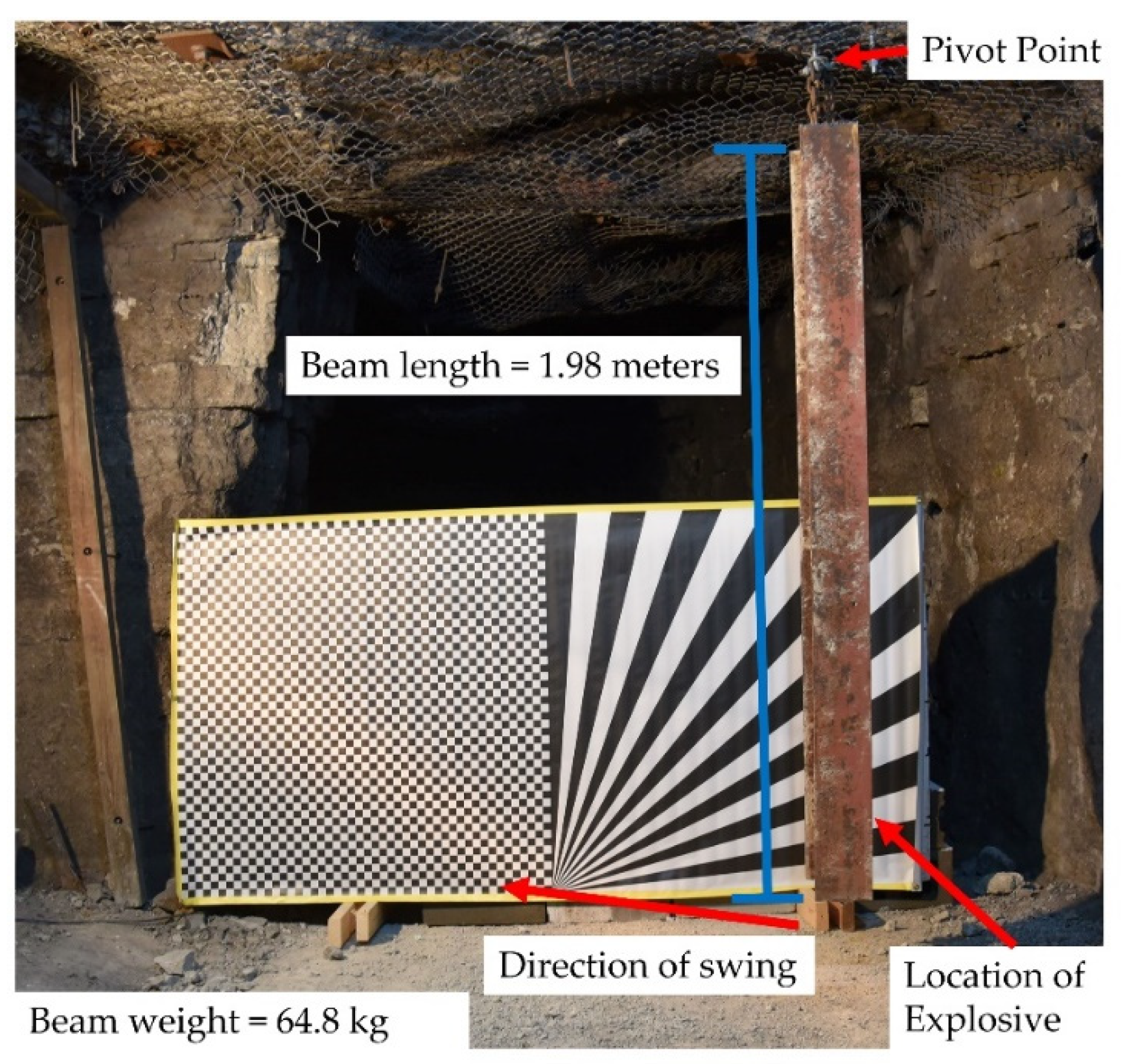
28] and designed to act as a severed column. Demolition projects involve cutting a column above and below the explosive charge to create a column that can be “kicked” out by the kicker charge. The test set-up mimics a column that has been severed and is ready to be kicked out of alignment. This material was chosen for its common use in construction and configuration in the test arena. This column was 1.98 m long and weighed 64.8 kg (kg). A chain was strung through a hole in the column and attached to a roof bolt in an underground limestone test arena. The column was aligned to swing in one direction and to reduce twisting of the column to just study motion from the explosive. The test set-up can be seen in
Figure 1.
For the first test, a 20.32 cm (cm) length and 3.17 cm diameter stick of Dyno Nobel Unimax dynamite [
29] was secured to the bottom of the column using a zip tie and tape. The charge was 227 g, and the bottom was placed 20.32 cm above the bottom of the column. The dynamite has a velocity of detonation of 5300 m per second (m/s) [
30]. This test set-up is designed to follow the design of a traditional kicker charge most closely.
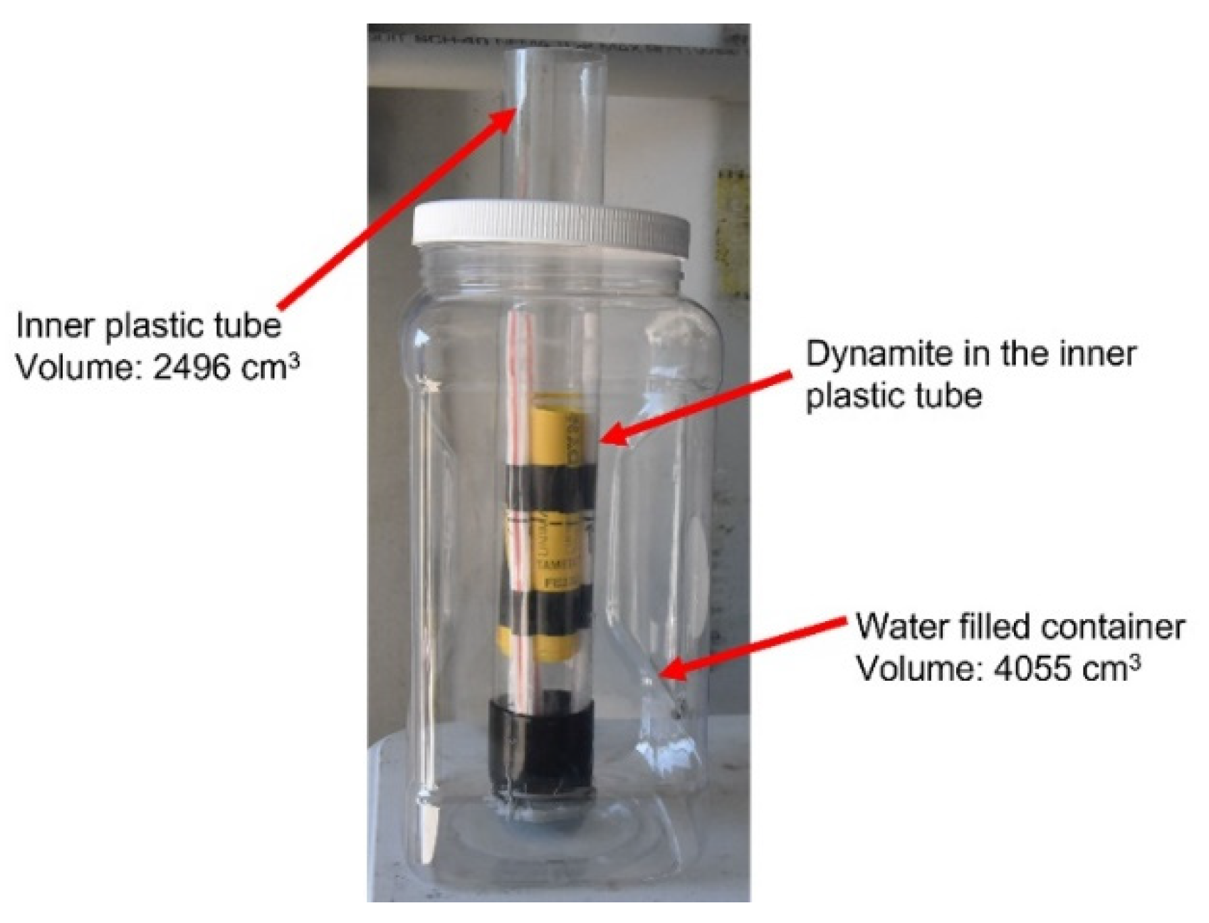
The second test used a water-cased kicker charge consisting of a 3.78 L plastic container, dynamite, and an inner plastic tube for the explosive that contains no water. This setup can be seen in
Figure 2. The container had a volume of 4055 cubic centimeters (cm
3) and the inner tube had a volume of 2496 cm
3. This creates a total of 1559 cm
3 of water. Container dimensions are 2.24 cm by 2.02 cm by 3.99 cm. The inner plastic tube was 4.33 cm tall with a diameter of 4.1 cm. The container was chosen for its optimal size to fit on most columns and purchase accessibility.
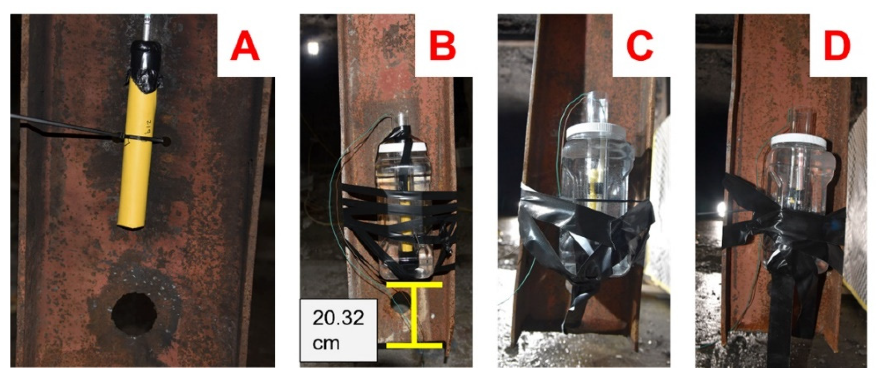
The inner plastic tube held a 20.32 cm length, 3.17 cm diameter, and 227 g stick of Dyno Nobel Unimax dynamite, the same charge from the first test for a direct energy comparison. The 3.78 L plastic container was filled with water, and then the inner plastic tube was placed in the center. Tape was used to hold the inner plastic tube in the center, and then the 3.78 L container was zip tied and taped to the web of the column in
Figure 3B. The bottom of the charge was placed 20.32 cm from the bottom of the column.
The third test consisted of a 10.16 cm length, 3.17 cm diameter, and 113.5 g stick of Dyno Nobel Unimax dynamite in the center (height wise) of the water-cased charge. This test used half the amount of dynamite from the first 2 tests. The dynamite was placed in the center of the inner plastic tube and the 3.78 L plastic container was attached to the column using zip ties and tape seen in
Figure 3C.
The final test consisted of a 5.08 cm length, 3.17 cm diameter, and 56.75 g stick of Dyno Nobel Unimax dynamite placed in the center (height wise) of the water-cased charge. This final water-charge used a quarter of the amount of dynamite from the first 2 tests and was assembled and attached to the column in the same way as the other water-cased charges. Just as in the other tests, the bottom of the charge was placed 20.32 cm above the bottom of the column (
Figure 3D). All tests were initiated using Austin Powder Rockstar electric blasting caps [
31].
Velocity, recorded with GoPros, was analyzed using phantom camera control (PCC) software [
32,
33] at 240 frames per second. One Go Pro was placed with a head-on view of the column with another at a side-on view of the column. The side view showed the flange of the column and the swing angle. A head on view showed the web of the column.
A common occurrence in Go Pro videos is the presence of fisheye distortion [
34,
35]. This allows for a wide view but can cause the edge of the lens to distort light that enters. As the beam was hung in the center of the Go Pro field of view, the object itself was not distorted and measurements were not taken from any area that could have been distorted. Although measurements were not taken from areas of the video with distortion, Adobe Premier Pro [
36] was used to remove the distortion from the videos and all measurements were taken using videos without fisheye.
The TNT equivalency for each charge was calculated using Equation (1) as recommended by the unified facilities criteria manuals [
17].
In the equation,
Qexp is the heat of detonation of the explosive in question,
QTNT is the heat of detonation of TNT, and
d is 0.76862 a constant used to represent the “Y-intercept of the straight curve of the heat of detonation TNT equivalent graph” [
37]. Resulting charge equivalencies can be found in
Table 1.
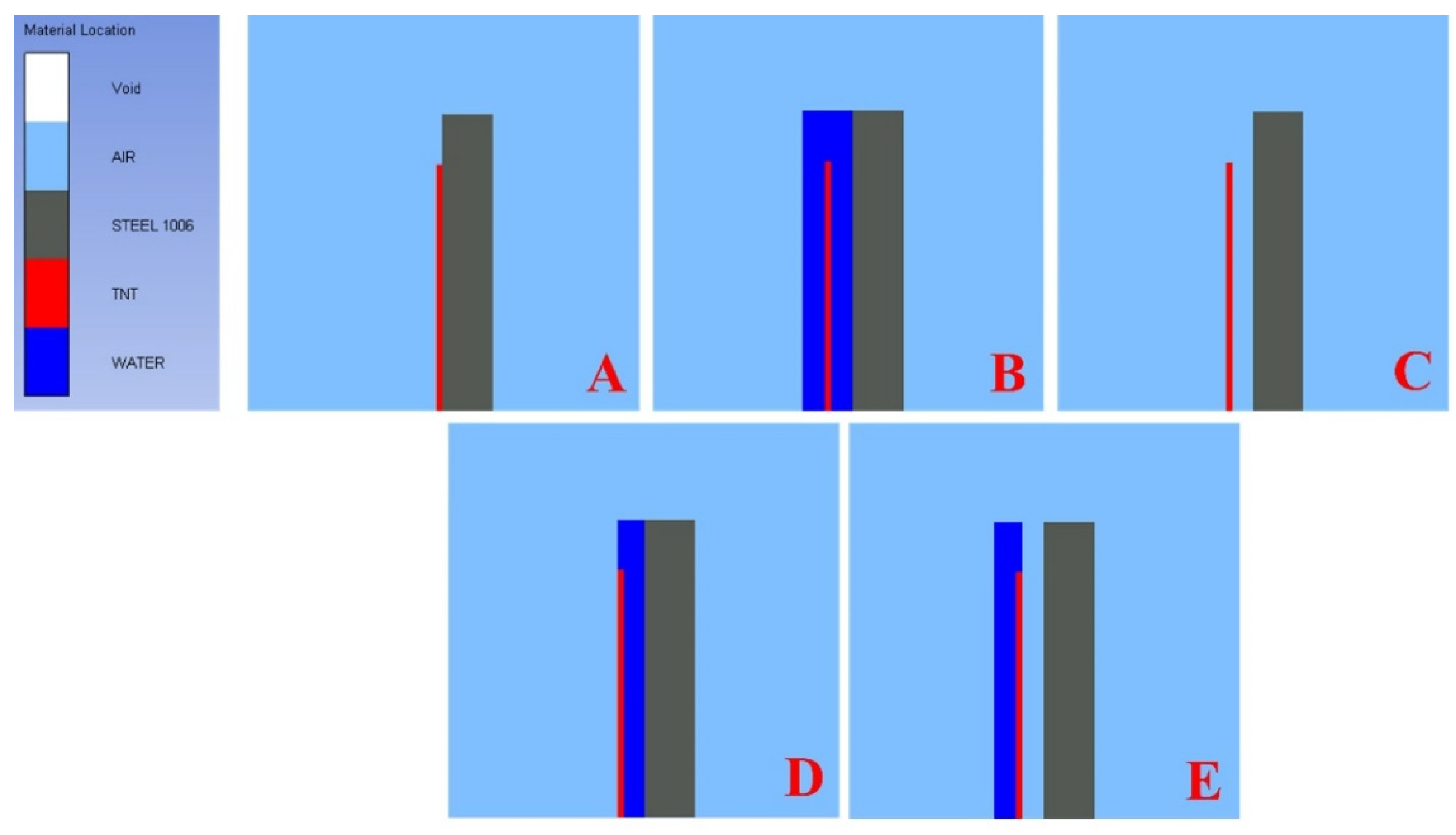
To fully understand the mechanisms inside the water-cased charge, a two dimensional axially symmetric coupled Eulerian–Lagrangian simulation was used to model the movement of a plate when explosive energy is applied with and without water in Ansys Autodyn 2021 R1 and is shown in
Figure 4. The simulations were, a charge in contact with the plate (
Figure 4A), a water-cased charge (
Figure 4B), an air-cased charge (
Figure 4C), a charge with water behind and air in front (
Figure 4D), then a charge with water between the plate and the explosive (
Figure 4E). These simulations will help investigate of the tamping effects of water compared to air.
A 30.48 cm tall and 2.54 cm thick plate was modeled with a 13 × 76 Lagrangian grid along the axis of symmetry using a linear hardening Equation of State and a Johnson–Cook strength model for Steel 1006 [
38]. The Lagrangian plate was coupled to a Eulerian atmospheric air domain of 38 cm long by 38 cm tall with a 401 × 401 element grid. The grid did not include universal flow out boundaries as they were not necessary to find maximum velocity and pressure of the plate. A 25.4 cm by 0.3175 cm mass of 263 g TNT was placed in the air domain either in contact with the plate or 5.08 cm away from the plate depending on the simulation setup. TNT initiation was modeled using a Jones–Wilkins–Lee equation of state in the air domain. A linear initiation was used to best simulate the effect of a standard explosive used for kicker charges. Water was modeled using the input data from Autodyn as a polynomial equation of state. Different amounts of water were used for different simulations using geometrical fill options.
The simulation was used to numerically identify the how much the water behind or in front of the water-cased charge was contributing to velocity differences seen through experimental tests.
3. Results
Four separate experimental tests were conducted to determine the effect water-cased charges have on kinematic properties of a hanging column. The test area was an underground limestone mine where steel columns were hung from the roof and allowed to swing freely. Using the swing of each column, velocity as well as impulse was calculated using point tracking and PCC software. All equations assume a linear velocity for the column and use the total mass of the column for calculations. Another assumption is the entire column is in motion even though it is hung from the roof. These calculations show the relative strength comparison for the explosive and are not meant to be exact values from the explosive. The hanging column is used for a comparison to demolition projects where columns are severed, and the kicker charges move one end of the column out of alignment.
The experimental tests conducted included a traditional dynamite kicker charge that was in contact with the column, a water-cased kicker charge with the same amount of dynamite, a water-cased charge with half the amount of dynamite and a water-cased charge with a quarter the amount of dynamite by mass. All four charges swung up into the roof of the limestone test arena, thus the full swing of the columns was not measured. Each column was tracked to a swing of 40 degrees to keep calculations consistent and easily compare calculated values. All columns reached maximum velocity prior to the 40-degree angle and were accurately tracked using the bottom corner of the column.
In Equation (2), J is impulse, F is force on the column in Newtons, and t is time in seconds.
Examination of the beams showed that water charges did not fragment or fracture the column while tamping the explosive and creating faster moving columns. The traditional charge with the dynamite in direct contact with the column produced a fracture down the center of the column (
Figure 5A). Water-cased charges produced deformation and warping of the column, but no fragmentation.
Figure 5B shows the result of the water-cased charge with the same amount of dynamite as the traditional charge, flanges of the beam are stretched and warped but did not fragment.
Figure 5C,D shows the half and quarter water-cased charges with no fragmentation of the column.
Table 2 shows the calculated results for each of the experimental tests. The water-cased charge contains the same amount of dynamite as the traditional in contact charge but moves the column 53% faster.
The larger surface area of the water charges allows the force from the explosive to be spread out instead of being applied on a small point. This decreases the peak pressure on the beam, but increases the impulse as the force is applied over a longer time. In addition, the water increases the coupling of the shock wave to the column. Water improves contact and coupling with the increased surface area.
Table 2 shows that the water-cased charge has a higher impulse than the dynamite in contact. Water behind the charge tamps and directs the energy into the column assisting in motion. Reflected shock waves travel into the column where the water has provided good coupling and the reflected waves add to the increased velocity and impulse.
Water slows the initial transfer of energy but disperses the energy more by tamping and directing the energy into the column, allowing for an overall greater energy transfer. This energy transfer can be seen in
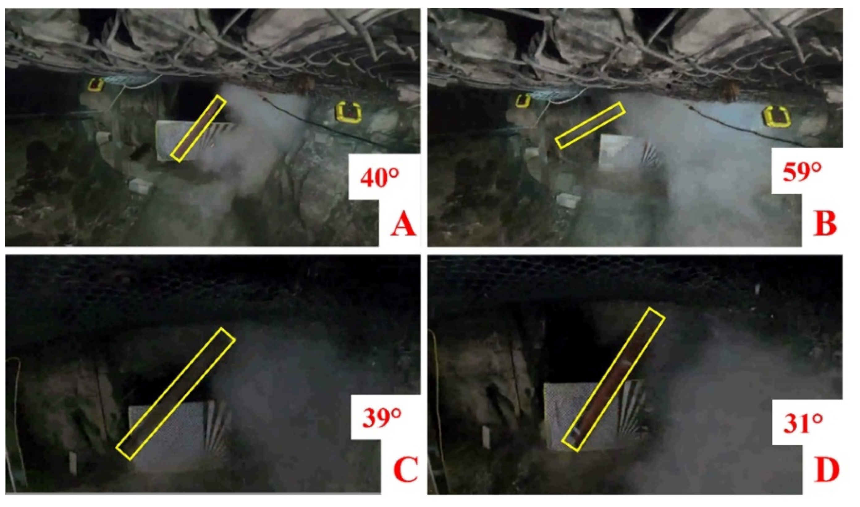
Figure 6 which shows all the charges 4 milliseconds (ms) after initiation. The water charges apply force for a longer amount of time on the column allowing the column to move faster than the traditional charge.
Figure 6A shows the traditional dynamite charge and
Figure 6B shows the dynamite water-cased charge with the same amount of dynamite as the traditional charge. This charge swings to a higher angle than the traditional dynamite charge in
Figure 6A over the same time duration. The water-cased charge has moved more than the traditional charge in the same time frame.
Figure 6C shows the half dynamite water-cased charge and
Figure 6D, the quarter dynamite water-cased charge. The half water-cased charge has moved to almost the same angle as the traditional charge in the same time frame. The water containers apply force to the column for a longer time over a larger area, creating a longer duration of force and resulting greater velocity and energy. Water behind the explosive assists in motion by tamping the charge and directing energy into the column contributing to the increased velocity. This phenomenon of directing energy has been utilized in breaching charges, but the amount of additional energy from the tamping material is unknown. Simulations were used to investigate this further to understand the mechanism of the water tamping.
Simulation
Experimental testing showed that water-cased charges could not only move columns faster and with more energy due to tamping, but also decrease the risk of fracture and fragmentation by decreasing pressure on the columns. A simulation study was conducted to fully understand the mechanism of energy and force production of water-cased charges. Ansys Autodyn was used to generate simulations of flyer plates with and without water. A total of 5 simulations were performed: a traditional in contact charge, water and air cased charges, a charge with water behind and air in front, and a charge with water in front (between the explosive and the plate). The simulations were used to show that the water charge assists in motion and causes the flyer plate to travel at a higher velocity when compared to air or in contact situations. The set-up and material location for each simulation can be seen in
Figure 4.
The flyer plate was allowed to move freely, and gauges were placed to measure the velocity of the plate. The maximum velocity of the plates was taken from gauge 2, the bottom of the flyer plate, shown in
Figure 7. Gauges were placed in the same location for each simulation regardless of material location. The water-cased charge caused the plate to travel faster than the traditional charge that was in contact with the plate by tamping the explosive and directing the energy into the plate. Water also decreased the pressure on the plate by distributing the pressure from the explosive over the plate decreasing the peak pressure.
Table 3 and
Table 4 show the plate velocity and pressure from the simulations at gauge 2. As the simulation and experimental test were not set up to be exact replicas, rather informative models, direct comparisons of velocity values are impractical. Percentage difference shows that the water-cased charges provide significantly more force and energy than traditional in contact charges. Experimental testing showed a 53% increase in velocity between the traditional charge and the water-cased charge while simulation showed a 43% increase in velocity between the same charges. The water-cased charge also decreases the pressure on the plate when compared the charge in contact. Water-cased charges provides the best outcome for both velocity and pressure of the plate.
The water charge assists in motion by increasing velocity while decreasing pressure. Much of the energy from the explosive in contact with the column is used to fracture or fragment the column as opposed to imparting force to drive the motion of the column. Water-cased charges provide ease of attachment to the column as well as a standoff from the column. The charge with an air casing provided sufficient velocity to move the plate as well as the lowest pressure but creating an air-cased charge experimentally is not worth the effort when simpler methods such as water-cased charges provide more velocity.
Having just water between the explosive and the plate moved the plate faster than the traditional charge, showing that increasing the surface area allowed the force to be spread over a greater area and increase the velocity. The water couples the shock wave to the beam with the larger surface area that the shock is distributed across. This decreases the peak pressure on the beam while increasing impulse as pressure is distributed over a greater amount of time. Water behind the charge with air between the plate and the charge resulted in a much faster plate velocity, but higher pressure felt on the plate. The water behind the explosive tamps the charge and redirects the energy towards the plate, increasing velocity and peak pressure. High density and incompressibility of the water result in a reflected shock wave. The wave is reflected due to the impedance mismatch of the air and water. High density water results in a strong reflected wave. Air between the charge and the plate does not couple the shock to the beam and results in higher peak pressure. The water-cased charge combines the tamping and reflection of forces behind the charge with the water in front that disperses the force over a larger area. Water allows the force to be distributed over a larger area while being coupled to the plate while increasing velocity from the water tamping.
The W 10 × 22 column has a flange length of 14.6 cm. This is the minimum distance the column would need to travel to kick the structural member out of alignment. Using this measurement and the cosine function, the minimum angle the column needs to travel is 4.22°. All four columns travel well over the minimum distance required to knock the structure out of alignment.
4. Discussion
Water-cased charges for use in explosive demolition were evaluated using experimental testing and computer simulations. Experimental testing showed that the water-cased charge produced a column that swung 53% faster than a traditional charge placed in contact with a column. Half the amount of dynamite for traditional kicker charges could be placed into water-cased charges, allowing demolition sites to reduce the amount of dynamite necessary. This is clearly shown as the half water-cased charge traveled to 39° and the charge in contact containing double the explosive mass traveled to 40° over the same time frame while having an increased velocity and impulse. Increased velocity of the column means that overall, less explosive can be used to produce the same effect as traditional charges. The experimental results were complemented through simulations in which water-cased charges moved a plate 43% faster than traditional uncased charges in contact with the plate. Water-cased charges also decreased pressure on the plate by 700,000 kPa. The simulated water-cased charge moved the plate at 103 m/s while the charge in contact moved the plate at 72 m/s. This 30 m/s increase in velocity was due to the effects of the water directing energy and force.
Water, as an incompressible fluid, reflects explosive forces into the column creating a faster moving column. Breaching charges use the same tamping phenomena to direct energy from water to result in successful entry to a building. The high density and incompressibility of the water, coupled with the impedance mismatch between water and air results in the reflection and direction of energy into the column. Water behind the charge drives the increase in velocity due to tamping and reflecting forces, but simulation shows that having the additional water between the charge and column is important as well. Water between the charge and the column applies the forces over a larger area decreasing pressure and risk of fragmentation or fracture. Water between the charge and the plate will decrease the velocity (77 m/s) when compared to just having water behind the charge (95 m/s). When combined in a water-cased charge the reflected forces still increase overall velocity compared to traditional charges while reducing pressure on the plate. Both the water behind and in front of the charge add to the increased velocity. The water behind provides a 32% increase in velocity while the water in front provides a 7% increase in velocity. Water in front of the charge also provides a 38% reduction in pressure on the plate.
Overall, the experimental testing and computer simulations showed that water-cased charges can be used successfully in explosive demolition. Water-cased charges produce a faster swinging column than traditional charges and require less explosive for the same effect. This leads to a safer demolition site with less risk of fragmentation or fracture. Water-cased charges offer a more efficient and effective solution to explosive demolition while also reducing the amount of explosives needed.
