
Development of an Adaptive Slicing Algorithm of Laminated Object Manufacturing Based 3D Printing for Freeform Formwork


Abstract
:1. Introduction
2. Methodology
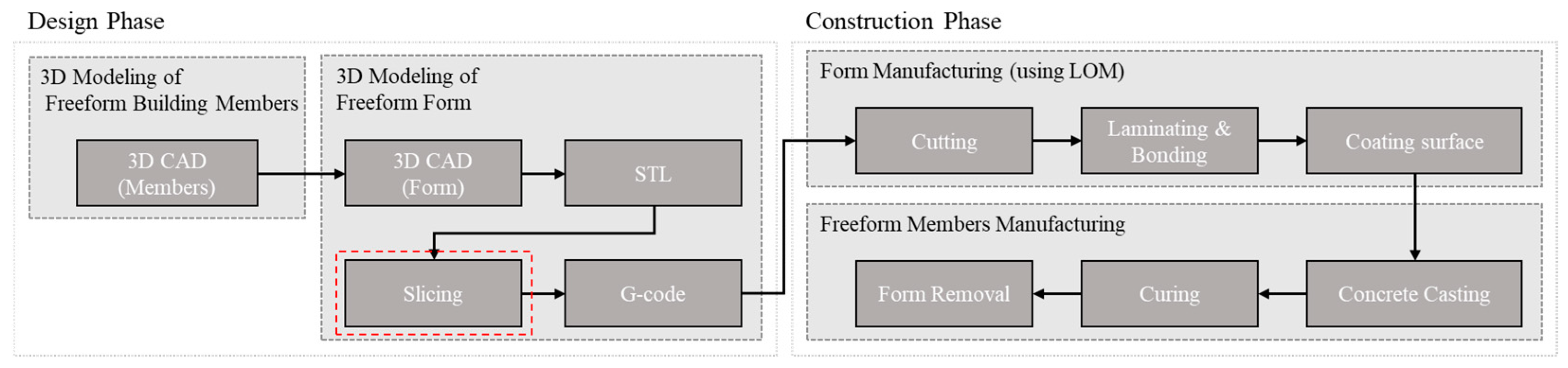
2.1. Overview of the Fabrication of LOM Formwork and the Fabrication of Freeform Buildings
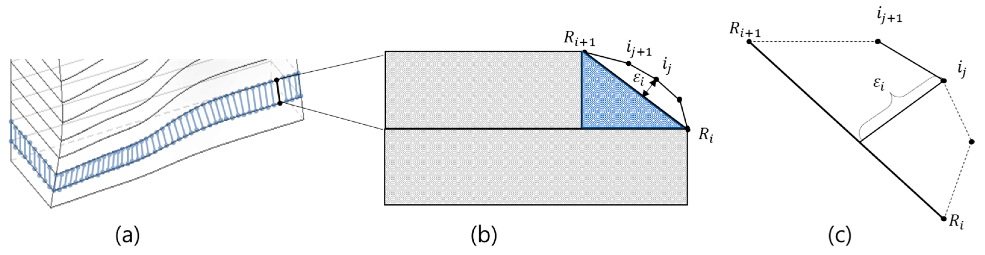
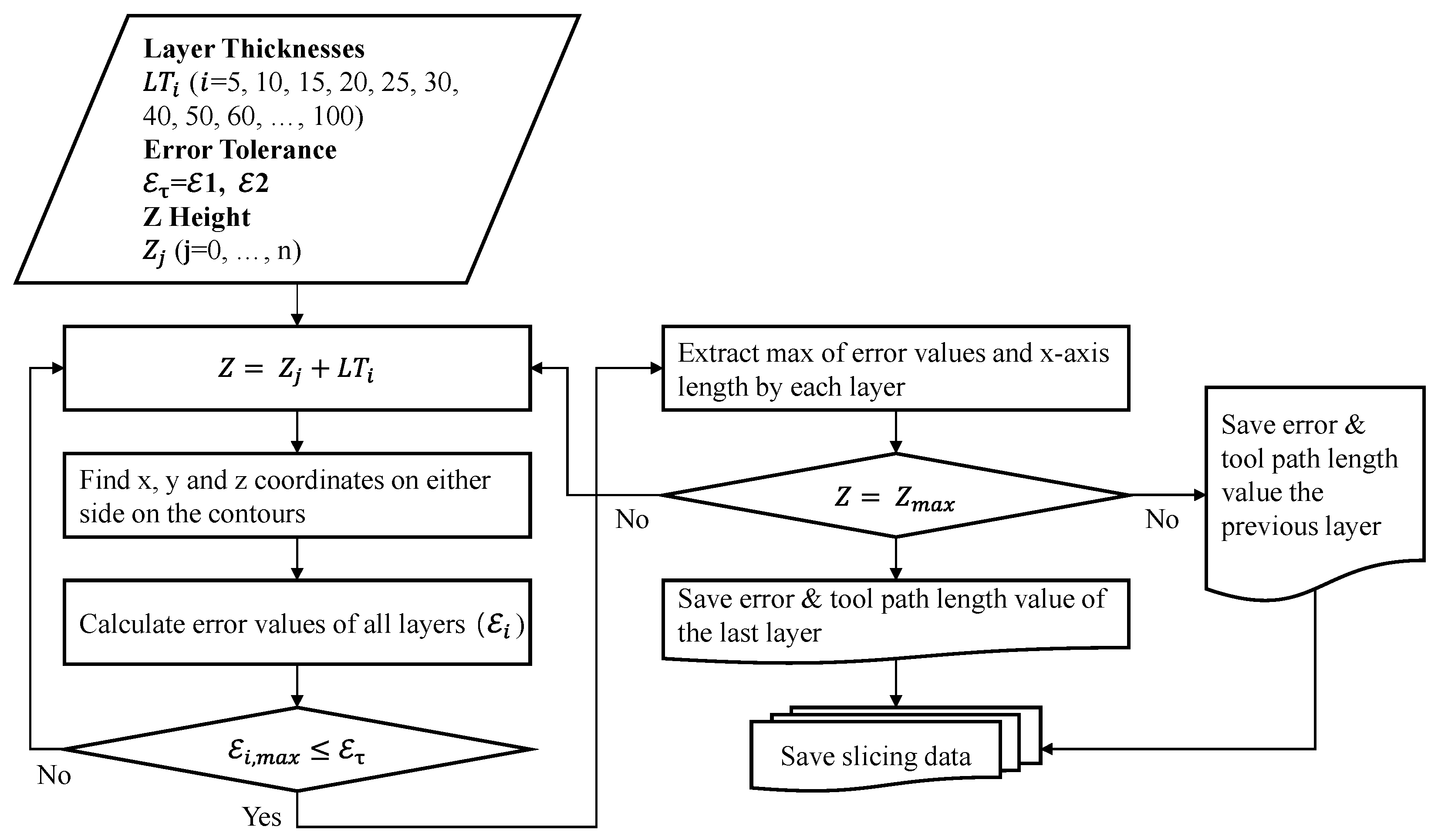
2.2. Slicing
- (1)
- Shape error
- (2)
- Thickness determination by the shape error
- (3)
- Calculation of production time
3. Experimental Setups
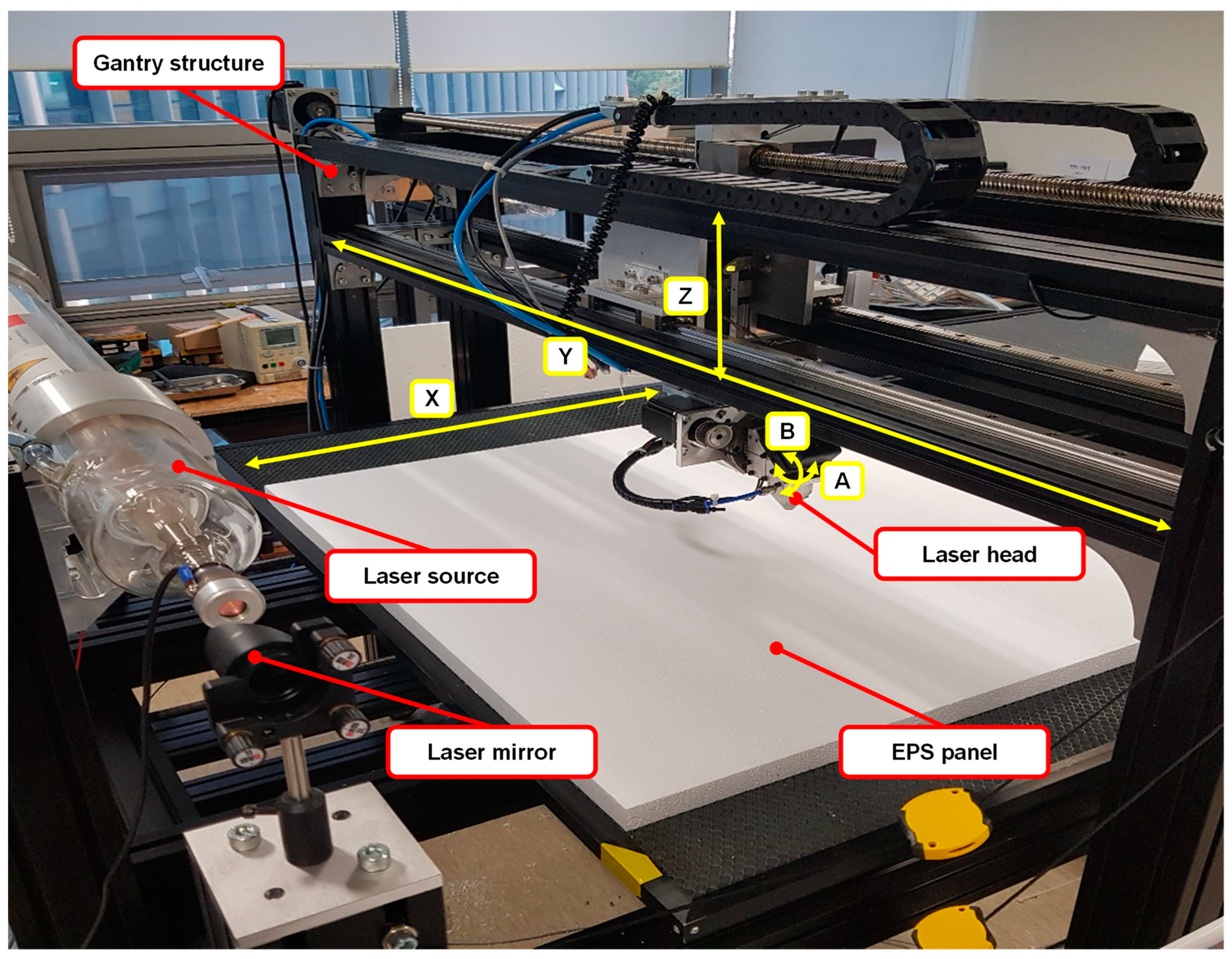
3.1. Equipment for Cutting EPS Form Panel
3.2. Target, Simulations, and Actual Fabrication
4. Results and Discussion
4.1. Simulation Results
4.2. Experimental Results from Production
4.3. Discussion
5. Conclusions
- This algorithm calculates the error of the ruled surface that is cut by the shape and the printer that is intended to be produced. It also suggests the range of tolerance according to the type of freeform building components, estimating the optimal alternative for freeform concrete form manufacturing.
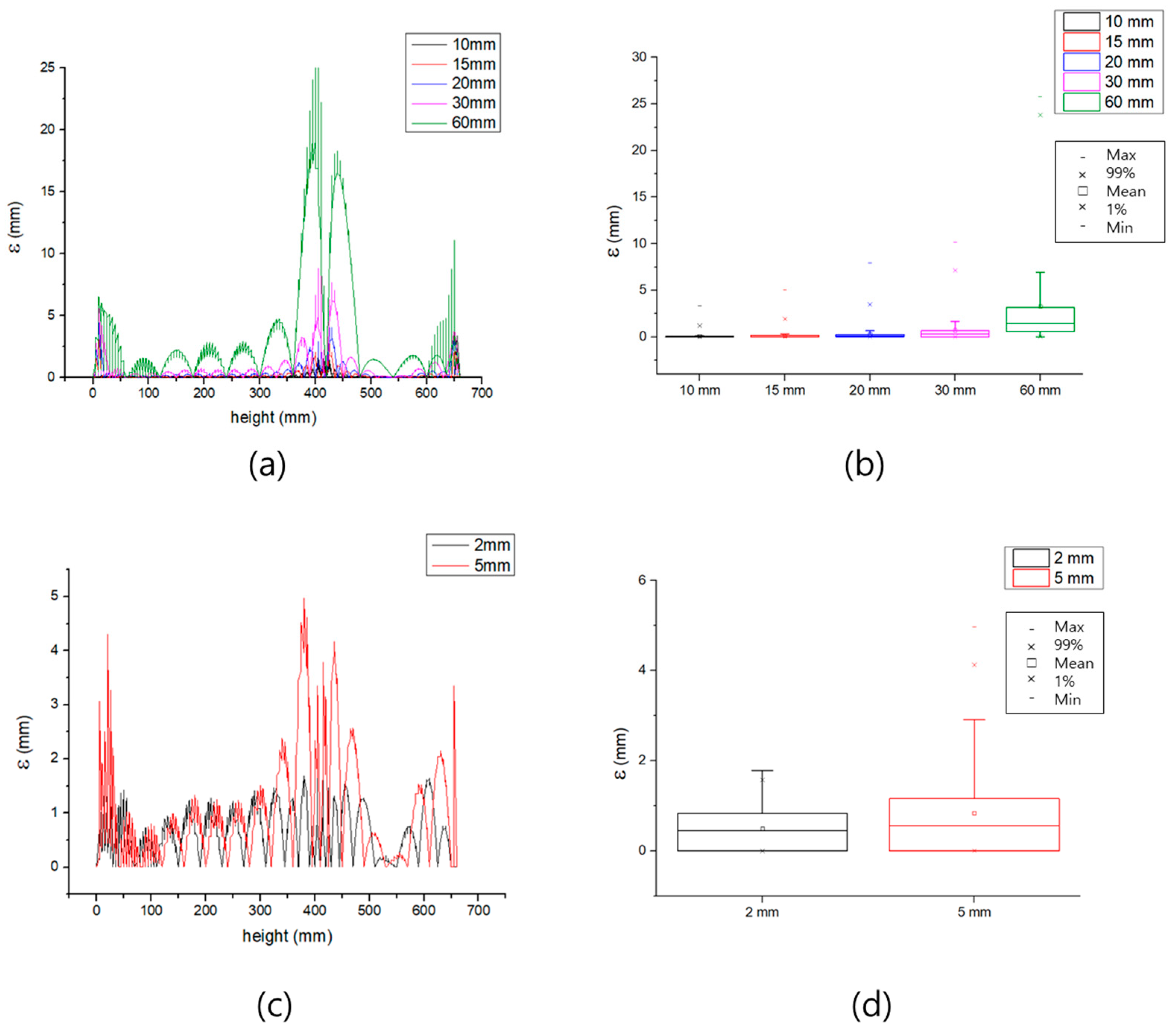
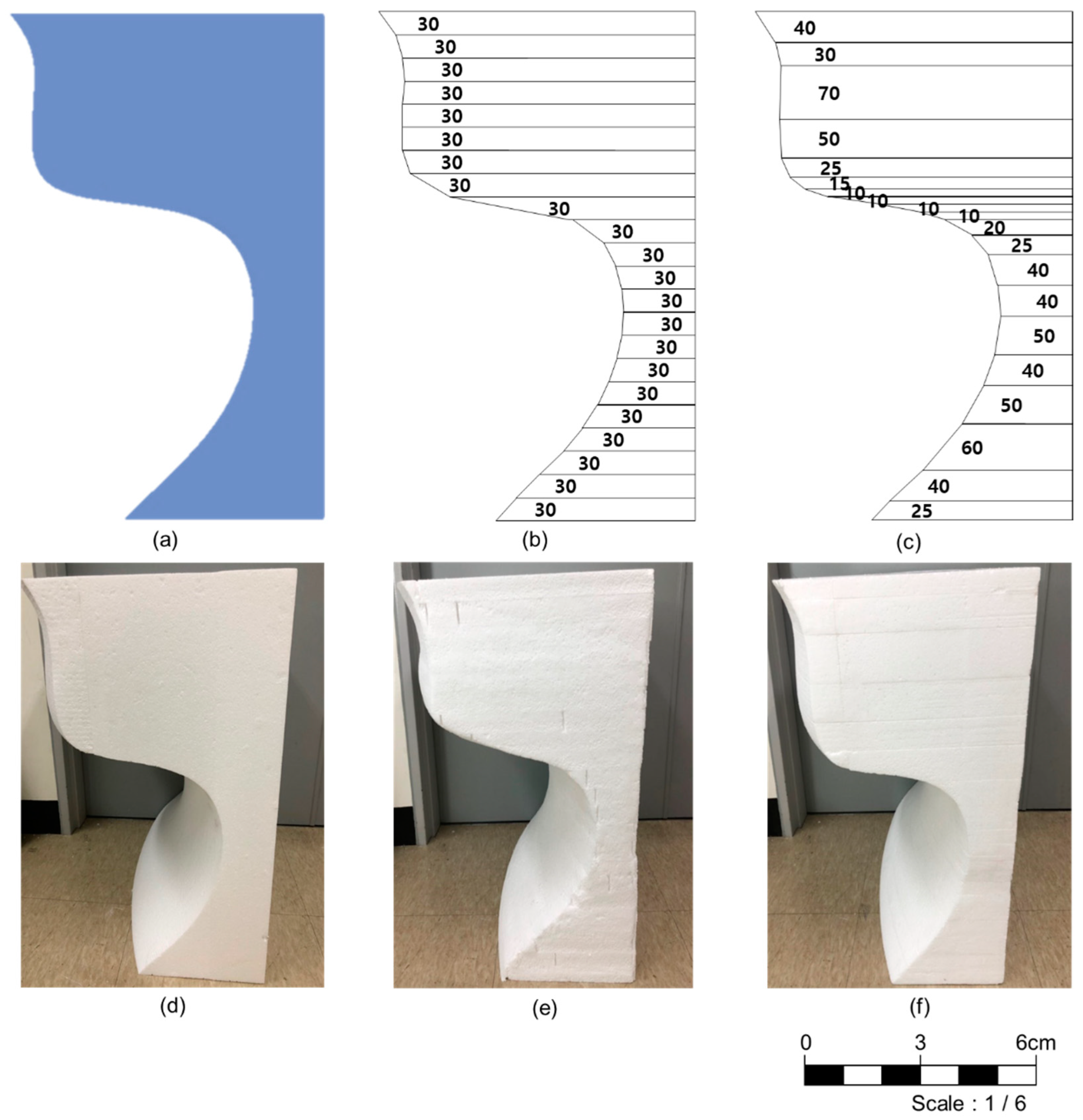
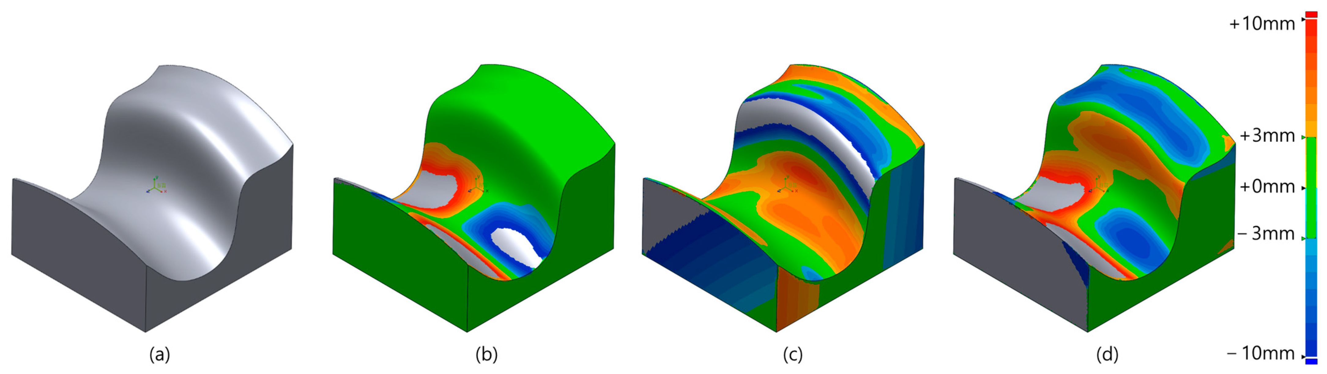
- According to the simulation results, in the case of a method of uniform slicing or constant thickness, there was no method to control or prepare the shape error. In the case of uniform slicing, a shape error of up to 25 mm occurs in a sharply curved part around 400 mm in height with respect to the test case, which is not suitable in terms of the esthetic nature of a freeform structure, and it is expected to cause undesirable effects on stronger curved shapes.
- For comparison, the target shape was also created by CNC milling. CNC milling was very good in terms of precision, but the average error of 0.2886 mm is too high of precision for construction sites, and it takes an overwhelming amount of time to remove this error.
- In the case of actual fabrication with respect to 30 mm uniform slicing, there was a severe error on the curved surface. When it comes to adaptive slicing with 2.0 mm criteria, the surface error is expected due to the processing error but is allowable in terms of the construction site.
- The time required was almost the same due to the similar number of layers in the adaptive process, but the time required was 151 min, even though the shape error was limited and lessened. There was this much difference in the test geometry conditions—only 600 mm by 600 mm with a height of 660 mm—but the difference would be very large when expanded to the entire wall and building.
Author Contributions
Funding
Institutional Review Board Statement
Informed Consent Statement
Data Availability Statement
Conflicts of Interest
References
- Buswell, R.A.; Soar, R.; Gibb, A.G.; Thorpe, A. Freeform Construction: Mega-Scale Rapid Manufacturing for Construction. Autom. Constr. 2007, 16, 224–231. [Google Scholar] [CrossRef]
- Bae, K.J.; Lee, S.H.; Jun, H.J. A Study on Digital Design Process of the Materialization of Free Form Design Architecture. Archit. Inst. Korea 2009, 29, 221–224. [Google Scholar]
- Hickert, S.; Knaack, U. Evaluation of free-form concrete architecture, moulding systems and their technical potentials. J. Facade Des. Eng. 2015, 3, 273–288. [Google Scholar] [CrossRef]
- Khoshnevis, B. Automated construction by contour crafting—related robotics and information technologies. Autom. Constr. 2004, 13, 5–19. [Google Scholar] [CrossRef]
- Khoshnevis, B.; Hwang, D.; Yao, K.-T.; Yeh, Z. Mega-scale fabrication by contour crafting. Int. J. Ind. Syst. Eng. 2006, 1, 301–320. [Google Scholar] [CrossRef]
- Leach, N.; Carlson, A.; Khoshnevis, B.; Thangavelu, M. Robotic construction by contour crafting: The case of lunar construction. Int. J. Archit. Comput. 2012, 10, 423–438. [Google Scholar] [CrossRef]
- Wu, P.; Wang, J.; Wang, X. A Critical Review of the Use of 3-D Printing in the Construction Industry. Autom. Constr. 2016, 60, 21–31. [Google Scholar]
- Kolarevic, B. Digital fabrication: Manufacturing architecture in the information age. In Reinventing the Discourse—How Digital Tools Help Bridge and Transform Research, Education and Practice in Architecture [Proceedings of the Twenty First Annual Conference of the Association for Computer-Aided Design in Architecture]; Buffalo: New York, NY, USA, 2001. [Google Scholar]
- Martins, P.F.; Campos, P.F.; Nunes, S.; Sousa, J.P. Expanding the material possibilities of lightweight prefabrication in concrete through robotic hot-wire cutting-form, texture and composition. In Proceedings of the 33rd eCAADe Conference, Vienna, Austria, 16–18 September 2015; Volume 2, pp. 341–351. [Google Scholar]
- Li, W.; Lin, X.; Bao, D.W.; Xie, Y.M. A review of formwork systems for modern concrete construction. Structures 2022, 38, 52–63. [Google Scholar]
- Bak, D. Rapid prototyping or rapid production? 3D printing processes move industry towards the latter. Assem. Autom. 2003, 23, 340–345. [Google Scholar] [CrossRef]
- Brooks, H.; Aitchison, D. A review of state-of-the-art large-sized foam cutting rapid prototyping and manufacturing technologies. Rapid Prototyp. J. 2010. [Google Scholar] [CrossRef]
- Mekonnen, B.G.; Bright, G.; Walker, A. A study on state of the art technology of laminated object manufacturing (LOM). In CAD/CAM, Robotics and Factories of the Future; Springer: Berlin/Heidelberg, Germany, 2016; pp. 207–216. [Google Scholar]
- Ahn, D.-G.; Lee, S.-H.; Yang, D.-Y. Development of transfer type variable lamination manufacturing (VLM-st) process. Int. J. Mach. Tools Manuf. 2002, 42, 1577–1587. [Google Scholar] [CrossRef]
- Lee, S.; Ahn, D.; Yang, D.-Y. Cutting path generation of linear hotwire cutter for VLM-ST. Int. J. Adv. Manuf. Technol. 2006, 30, 401–415. [Google Scholar] [CrossRef]
- Suh, Y.S.; Wozny, M.J. Adaptive slicing of solid freeform fabrication processes. In Proceedings of the 1994 International Solid Freeform Fabrication Symposium, Austin, TX, USA, 8–10 August 1994. [Google Scholar]
- Kulkarni, P.; Dutta, D. An accurate slicing procedure for layered manufacturing. Comput.-Aided Des. 1996, 28, 683–697. [Google Scholar] [CrossRef]
- Hope, R.; Roth, R.; Jacobs, P. Adaptive slicing with sloping layer surfaces. Rapid Prototyp. J. 1997, 3, 683–697. [Google Scholar] [CrossRef]
- Huang, B.; Singamneni, S. Alternate slicing and deposition strategies for fused deposition modelling of light curved parts. J. Achiev. Mater. Manuf. Eng. 2012, 55, 511–517. [Google Scholar]
- Koc, B.; Lee, Y.-S. Adaptive ruled layers approximation of STL models and multiaxis machining applications for rapid prototyping. J. Manuf. Syst. 2002, 21, 153–166. [Google Scholar]
- Koc, B. Adaptive layer approximation of free-form models using marching point surface error calculation for rapid prototyping. Rapid Prototyp. J. 2004. [Google Scholar] [CrossRef]
- Ma, W.; But, W.-C.; He, P. NURBS-based adaptive slicing for efficient rapid prototyping. Comput.-Aided Des. 2004, 36, 1309–1325. [Google Scholar] [CrossRef]
- Mao, H.; Kwok, T.-H.; Chen, Y.; Wang, C.C.L. Adaptive slicing based on efficient profile analysis. Comput.-Aided Des. 2019, 107, 89–101. [Google Scholar]
- Qian, X.; Dutta, D. Feature based fabrication in layered manufacturing. J. Mech. Des. 2001, 123, 337–345. [Google Scholar]
- Wang, W.; Chao, H.; Tong, J.; Yang, Z.; Tong, X.; Li, H.; Liu, X.; Liu, L. Saliency-Preserving Slicing Optimization for Effective 3D Printing. Comput. Graph. Forum 2015, 34, 148–160. [Google Scholar]
- Szilvśi-Nagy, M.; Matyasi, G. Analysis of STL files. Math. Comput. Model. 2003, 38, 945–960. [Google Scholar] [CrossRef]
- Lawson, C.L. Software for C1 surface interpolation. In Mathematical Software; Elsevier: Amsterdam, The Netherlands, 1977; pp. 161–194. [Google Scholar]
- Lu, M.; Chen, M.; Wang, X.; Min, J.; Liu, A. A spatial lattice model applied for meteorological visualization and analysis. ISPRS Int. J. Geo-Inf. 2017, 6, 77. [Google Scholar]
- Chan, D.W.; Kumaraswamy, M.M. An evaluation of construction time performance in the building industry. Build. Environ. 1996, 31, 569–578. [Google Scholar]
- Chidambaram, R.; Narayanan, S.; Idrus, A.B. Construction delays causing risks on time and cost-a critical review. Australas. J. Constr. Econ. Build. 2012, 12, 37–57. [Google Scholar]
- Kim, H.; Sim, J.; Jeong, S.; Hong, D. A Study on Optimal Cutting Condition of EPS Foam Cutting Based on Collimated CO2 Laser Beam. J. Korean Soc. Precis. Eng. 2019, 36, 859–865. [Google Scholar] [CrossRef]
- Sim, J.; Kim, H.; Park, K.; Kim, C.; Hong, D. Manufacturing Automation System of Freeform Concrete Formwork Using S-LOM Method. J. Korean Soc. Precis. Eng. 2020, 37, 43–50. [Google Scholar] [CrossRef]
- Jeong, S.; Sim, J.; Kim, H.; Shin, D.; Hong, D. Application of LOM for Freeform Architecture. J. Korean Soc. Precis. Eng. 2017, 34, 903–909. [Google Scholar] [CrossRef]
- Wyevale Precast. A Combination Free Form Bench and Retaining Wall. Available online: http://www.wyevaleconcrete.com/Content/Waterpark_City/ (accessed on 19 July 2022).
- Hexagon. StereoScan Neo Data Sheet. Available online: https://www.hexagonmi.com/products/structured-light-scanners/aicon-stereoscan-neo (accessed on 19 July 2022).

| Items | Content |
|---|---|
| Laser type | CO₂ laser tube |
| Laser power | Max 75 W |
| Frame size (W × D × H) ※ | 1580 mm × 1400 mm × 1530 mm |
| Workspace (W × D × H) ※ | 1500 mm × 1320 mm × 100 mm |
| Cutting velocity | 26.7~41.7 mm/s |
| Cutting range of angle | −60° ≤ θ ≤ 60° |
| Items | Contents | Design (One of Module) | |
|---|---|---|---|
| Bench | Form | ||
| Project name | Waterpark City Freeform bench | 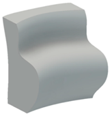 |  |
| Material | Concrete/EPS | ||
| Number of modules | 28 | ||
| Size (W × L) ※ | 600 mm × 660 mm | ||
| Angle of tangential plane | 5° ≤ ≤ 120° | ||
| 10 mm Uniform | 15 mm Uniform | 20 mm Uniform | 30 mm Uniform | 60 mm Uniform | 2 mm Adaptive | 5 mm Adaptive | |
|---|---|---|---|---|---|---|---|
| Number of layers | 66 | 44 | 33 | 22 | 11 | 20 | 15 |
| mean (mm) | 0.0535 | 0.1391 | 0.2751 | 0.7128 | 3.2798 | 0.4973 | 0.8363 |
| standard deviation | 0.1802 | 0.3314 | 0.5853 | 1.3770 | 5.1956 | 0.4696 | 0.9721 |
| maximum (mm) | 3.3541 | 5.0596 | 7.9131 | 10.1825 | 25.7666 | 1.7848 | 4.9684 |
| Tool path (mm) | 41,837 | 27,841 | 20,890 | 13,951 | 7014 | 12,712 | 9522 |
| Cutting time (min) | 116 | 77 | 58 | 39 | 19 | 35 | 26 |
| Plastering time (min) | 49.5 | 33 | 24.75 | 16.5 | 8.25 | 15 | 11.25 |
| Curing time (min) | 90 | 90 | 90 | 90 | 90 | 90 | 90 |
| Minimum manufacturing time (min) | 256 | 200 | 173 | 145 | 118 | 140 | 128 |
| CNC Milling | Uniform Slicing | Adaptive Slicing | |
|---|---|---|---|
| Number of layers | - | 22 | 20 |
| mean (mm) | −0.2886 | −3.5438 | −1.6529 |
| standard deviation | 2.0419 | 6.0466 | 4.0424 |
| maximum (mm) | 21.6269 | 20.5244 | 16.6693 |
| minimum (mm) | 0.0021 | 0.4130 | 0.0917 |
| Cutting time (min) | 348 | 39 | 35 |
| Plastering time (min) | - | 17 | 15 |
| Curing time (min) | - | 90 | 90 |
| Sanding time (min) | - | 12 | 10 |
| Total manufacturing time (min) | 348 | 158 | 151 |
Publisher’s Note: MDPI stays neutral with regard to jurisdictional claims in published maps and institutional affiliations. |
© 2022 by the authors. Licensee MDPI, Basel, Switzerland. This article is an open access article distributed under the terms and conditions of the Creative Commons Attribution (CC BY) license (https://creativecommons.org/licenses/by/4.0/).
Share and Cite
Lee, D.; Hong, J. Development of an Adaptive Slicing Algorithm of Laminated Object Manufacturing Based 3D Printing for Freeform Formwork. Buildings 2022, 12, 1335. https://doi.org/10.3390/buildings12091335
Lee D, Hong J. Development of an Adaptive Slicing Algorithm of Laminated Object Manufacturing Based 3D Printing for Freeform Formwork. Buildings. 2022; 12(9):1335. https://doi.org/10.3390/buildings12091335
Chicago/Turabian StyleLee, Dongyoun, and Junho Hong. 2022. "Development of an Adaptive Slicing Algorithm of Laminated Object Manufacturing Based 3D Printing for Freeform Formwork" Buildings 12, no. 9: 1335. https://doi.org/10.3390/buildings12091335
APA StyleLee, D., & Hong, J. (2022). Development of an Adaptive Slicing Algorithm of Laminated Object Manufacturing Based 3D Printing for Freeform Formwork. Buildings, 12(9), 1335. https://doi.org/10.3390/buildings12091335